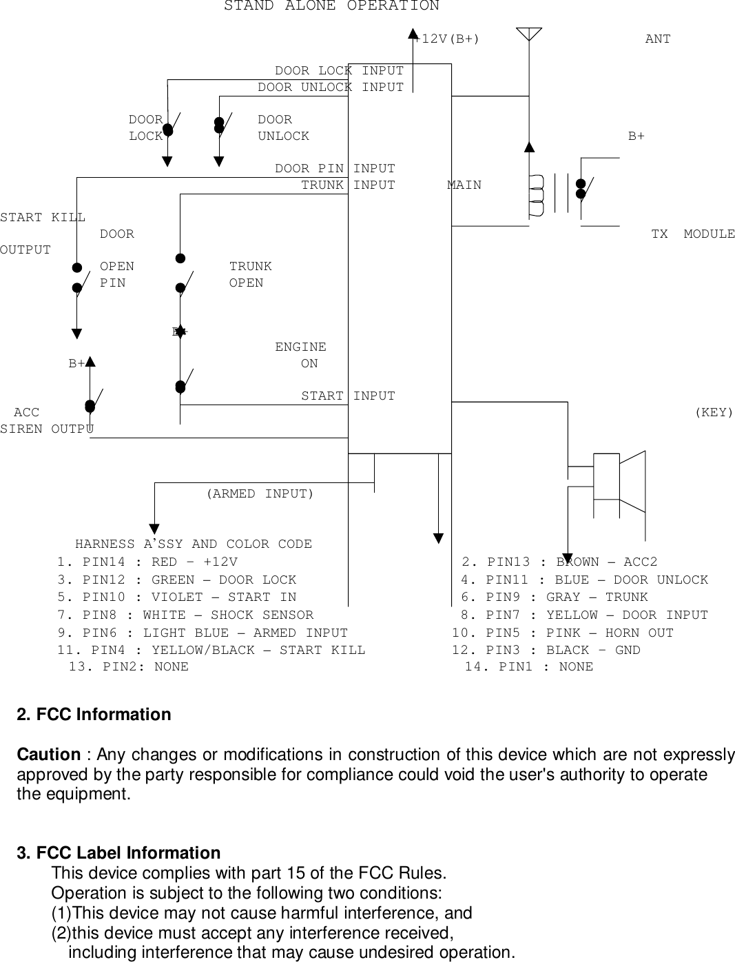
drakesystem DSCAB002 Car Pager User Manual Users manual

drakesystem co.,ltd Car Pager Users manual

Users manual

USERS MANUALSP-1001ROperating Instructions1.INSTRUCTION MANUALTABLE OF CONTENTS   1-1. THE USE OF PAGER     1-1-1.  LCD DISPLAY OF PAGER     1-1-2.  INSERTING BATTERY INTO THE PAGER     1-1-3.  FUNCTION OF BUTTON     1-1-4.  THE USAGE OF MODE KEY     1-1-5.  THE USAGE OF PARKING TIMER     1-1-6.  THE EXCHANGE OF BATTERY     1-1-7.  RF RECEIVING ON/OFF     1-1-8.  HOW TO LEARN ID
     1-1-9.  THE OPERATION WHEN INSTALLED     1-1-10. ARM DELAY MODE 1-2. THE USE OF PAGER  1-2-1.  LCD DISPLAY OF PAGER                          13      1    2    3   4     5    6    7       8    9        10     11      12      • ANTENNA      • LOW BATTERY INDICATOR      • DOOR LOCK      • DOOR UNLOCK      • ALERT TONE      • VIBRATION      • RF RECEIVING ON/OFF      • CAR SHAPE (WHEN SHOCK-SENSOR IS TRIGGERED, ICONBLINKING)      • DOOR OPEN      • PARKING ALARM TIMER      • WAKE-UP TIMER      • CLOCK      • TRUNK OPEN  1-2-2.  INSERTING BATTERY INTO THE PAGER    •A pager turns on all of LCD icons and backlight with alerttone and       vibration  when  the  battery  (AAA  alkaline)  is  insertedinto the pager.    •Please remove and re-insert the battery when receiver doesnot operate       like this.    •The alert tone is repeated five times, but it is stoppedinstantly       when any button on the receiver is pressed .  1-2-3.  FUNCTION OF BUTTON    •The right button is MODE KEY which is used for the settingof each       function and time.    •The left button is PARKING KEY whitch is used for parkingtimer.  1-2-4.  THE USAGE OF MODE KEY
    •The receiver enters into the change of MODE with beep tonewhen the      MODE KEY is pressed for more then 2 seconds.    •The procedure for the change of MODE is as follows.       • RF RECEIVING ON/OFF       • SELECT OF ALERT TONE or VIBRATION       • ADJUST OF CLOCK       • WAKE-UP ALARM ON/OFF       • ADJUST OF WAKE-UP ALARM TIME        •The left button will be used when the change of MODE isrequired.        •When  the  MODE-KEY  is  usually  pressed  shortly,  the  MODE-KEY is usedfor the display of previous status or reset of currentstatus.      1-2-5.  THE USAGE OF PARKING TIMER    •The receiver enters into change of PARKING TIMER with beeptone when      the left button is pressed for more then 2 seconds. Atthat time, the      clock on the LCD will blank which enables the change ofPARKING TIMER.    •At this mode, the left button is used to increase the houror minute      when the icon is blanking and the right button is used tomove the      blinking icon to the right.    •The icon of PARKING TIMER is blanking when the PARKINGTIMER is being      operated The operation of PARKING TIMER is cancelled whenthe left      button is pressed for more then 2 seconds during theoperation of      PARKING TIMER.    •The previous PARKING TIMER is memorized in the memory ofthe receiver.      You can use the previous PARKING TIMERwhen you press the left button      for more than 2 seconds.  1-2-6.  THE EXCHANGE OF BATTERY    •Please  exchange  the  current  battery  with  new  batterywithin 2 days      when the icon of low battery on the LCD is turned on.    •The receiver memorizes the CURRENT MODE, ALARM TIME,PARKING TIME and      ID into the memory of the receiver, but it does notmemorize the      CURRENT TIME. When the battery is exchanged with newbattery, you should re-adjust your clock on the receiver.The current time will be set to 12:00 when you change thebattery.
  1-2-7.  RF RECEIVING ON/OFF    •The picture of car on the LCD will disappear when thereceiver is set      to OFF.    •The receiver cannot receive a call when the receiver isturned OFF or      the ID CODE does not match.    1-2-8.  HOW TO LEARN ID      •The receiver enters into the ID LEARLING mode when youpress two buttons for more then 2 seconds simultaneouslyand then, it blinks.        “Id”on the LCD. The  receiver learns the ID and  memorizesit if the        receiver receives the transmitted signal from tramsmitterwithin 30        seconds.  The  transmitted  signal  from  transmitter  can  begenerated when        DOOR  LOCK,  DOOR  UNLOCK,  TRUNK  OPEN,  SHOCK  SENSOR,  DOOROPEN is sensed.        When the receiver succeened in ID learning, the  receiversends triple        Short beep.    1-2-9.  THE OPERATION WHEN INSTALLED      1-2-9-1. STANT-ALONE OPERATION       •The  transmitter  enters  into  ARM  MODE  after  30  secondswhen the key is         removed from the key box and the transmitter enters intoDISARM MODE         just after that the car is started by key.MODE PARAMETEROPEERATIONOFTRANSMITTERLCD DISPLAYOF RECEIVERALERTTONE/VIBRATIONDOOR LOCK Instant  RFTX‘LOCK’ICON SINGLEBEEPDOOR UNLOCK Instant  RFTX‘UNLOCK’ICONDUAL BEEPTRUNK OPENInstant RFTX& SIRENTRUNK OPENALERT TONE(15 TIMES)SHOCKSENSORInstant RFTX& SIRENBLINKING OFCAR SHAPEALERT TONE(15 TIMES)ARMMODEDOOR OPEN30 secondwaitSIREN/STARTKILL/RF TXDOOR OPEN ALERT TONE(15 TIMES)
DOOR LOCK Instant  RFTX‘LOCK’ICON SINGLEBEEPDISARMMODE DOOR UNLOCK Instant  RFTX‘UNLOCK’ICONDUAL BEEP      1-2-9-2. OPERATION INSTALLED WITH CAR ALARM       •The transmitter enters  into  ARM  MODE  if  it  receives  ARMINPUT from         CAR  ALARM  and  enters  into  DISARM  MODE  if  it  does  notreceive         ARM INPUT.MODE PARAMETEROPERATION OFTRANSMITTERLCD DISPLAYOF RECEIVERALERTTONE/VIBRATIONDOOR LOCK Instant  RFTX‘LOCK’ICON SINGLEBEEPDOOR UNLOCK Instant  RFTX‘UNLOCK’ICONDUAL BEEPREMOTESTARTInstant RFTXBLINKING OFWHEELQUADRUPLEBEEPTRUNK OPENInstant RFTX& SIRENTRUNK OPENALERT TONE(15 TIMES)SHOCKSENSORInstant RFTX& SIRENBLINKING OFCAR SHAPEALERT TONE(15 TIMES)ARMMODEDOOR OPEN30 secondwaitSIREN/STARTKILL/RF TXDOOR OPENALERT TONE(15 TIMES)DOOR LOCK Instant  RFTX ‘LOCK’ICON SINGLEBEEPDOOR UNLOCK Instant  RFTX‘UNLOCK’ICONDUAL BEEPDISARMMODE REMOTESTARTInstant RFTXBLINKING OFWHEELQUADRUPLEBEEP        NOTE : The siren or START-KILL will be stopped instantlywhen the               Transmitter enters into DISARM mode.    1-2-10. ARM DELAY MODE    •When the transmitter enters into ARM mode, it has on ARMDELAY mode      between DISARM mode and ARM mode.
    1-2-10-1. STAND-ALONE OPERATION      At  the  stand-alone  operation,  the  transmitter  has  a  30seconds      ARM DELAY.The door-open and shock sensor do not operate during ARMDELAY.    1-2-10-2. OPERATION WITH CAR ALARM      The transmitter has a 5 seconds ARM DELAY in thisoperation.      The door lock and door unlock will operate during ARMDELAY. 1-3. INSTALLATION OF TRANSMITTER   1).Please connect all of input wires except BAT+, and thenconnect BAT+.      All  of  inputs  should  be  in  the  normal  condition  (Doorclosed/Trunk      Closed/Shock  sensor  not-operated/START-IN  not-operated/Door unlocked)      and then, BAT+ should be applied.   2).Please turn ON/OFF  the more then 3 times during 5seconds after BAT+      being  applied,  and  then,  the  transmitter  memorizes  thecondition of      input  lines  whether  it  is  positive  input  or  negativeinput. This      procedure should be done within 20 seconds after BAT+being applied, otherwise the transmitter fetches the datafrom memory after 20 seconds and acts by the data.   3).The ACC input and START-IN (REMOTE START) are alwayspositive input.      The  ARM_INPUT  is  used  to  determine  whether  thetransmitter is operated      STAND-ALONE or operated with CAR ALARM when installed.   4).OPERATION OF TRANSMITTER• STAND-ALONE OPERATIONThe transmitter will be operated STAND-ALONE when theARMED-INPUT is grounded before BAT+ being applied. At thismode, thetransmitter enters into ARM MODE when ACC INPUT isremoved and it enters into DISARM MODE when ACC INPUTis applied.            • OPERATION WITH CAR ALARM               The  transmitter  will  be  operated  with  CAR  ALARMwhen the ARMED-INPUT is floated or connected to the ARMED-OUTPUT of
CAR ALARM.        At this mode, the transmitter enters into ARM MODE byARMED-               OUTPUT being supplied from CAR ALARM.        • OPERATION OF EACH INPUT           When  any  input  is  sensed,  the  transmitter  sends  RFsignal only           once.  But  the  transmitter  does  not  send  RF  signalwhen the door           or  trunk  is  closed.  The  operation  of  each  input  ismentionedon the usage of pager. The transmitter can be usedboth STAND-ALONE and operation with CAR ALARM.5).The receiver should do ID LEARING, after the transmitterbeinginstalled. When two keys are pressed simultaneously formore then 2seconds, the receiver enters into ID LEARING MODE withbeep tone.At that time, the receiver shows “Id”on the LCD. If itreceives RFsignal from transmitter, the receiver decodes ID+DATA andmemorizes itinto memory in receiver. When the receiver succeeds in IDLEARING, thereceiver sounds triple beep tone and ends ID LEARING MODE.When the receiver does not succeed in ID LEARING for 30seconds, itends the ID LEARING MODE with single long beep.
1-3. WIRING DIAGRAMOPERATION WITH CAR ALARM                                                B+            B+                                         RF                         B+                                                                    B+     ANTENNA       B+                                                   ACC            ENGINE                                                  IN PUT           ON                                ACC INPUT                                           ACC INPUT                                ENGIN ON INPUT                                      START_INREMOTE          CAR     ARMED OUTPUT                                      ARMED INPUT     PAGER     START KILLOUTPUTCON-           ALARM    EXTERNAL SHOCK INPUT                      EXTENAL SHOCK INPUT    TRANAS-TROLLER                 TRUNK INPUT                                       TRUNK INPUT    MITTER                                DOOR UNLOCK OUTPUT                          DOOR UNLOCK INPUT                SIREN OUTPUT                                DOOR LOCK OUTPUT                              DOOR LOCK INPUTDOOR PIN INPUT                                 DOOR PIN INPUTDOOR         DOOR     DOOR     TRUNK    SHOCKOPEN         LOCK     UNLOCK   OPEN     SENSORHARNESS A’SSY AND COLOR CODE1. PIN14 : RED - +12V               2. PIN13 : BROWN - ACC2                    3. PIN12 : GREEN – DOOR LOCK4. PIN11 : BLUE – DOOR UNLOCK       5. PIN10 : VIOLET – START IN               6. PIN9 : GRAY – TRUNK7. PIN8 : WHITE – SHOCK SENSOR      8. PIN7 : YELLOW – DOOR INPUT              9. PIN6 : LIGHT BLUE – ARMED IN10. PIN5 : PINK – HORN OUT           11. PIN4 : YELLOW/BLACK – START KILL       12. PIN3 : BLACK - GND13. PIN2 : NONE                      14. PIN1 : NONE
STAND ALONE OPERATION                                                +12V(B+)                   ANT                                DOOR LOCK INPUT                              DOOR UNLOCK INPUTDOOR           DOORLOCK           UNLOCK                                     B+                             DOOR PIN INPUT                                TRUNK INPUT      MAINSTART KILLDOOR                                 TX MODULEOUTPUTOPEN           TRUNKPIN            OPEN                 B+                             ENGINE     B+                         ON                                START INPUTACC  (KEY)SIREN OUTPU               (ARMED INPUT)HARNESS A’SSY AND COLOR CODE1. PIN14 : RED - +12V                          2. PIN13 : BROWN – ACC23. PIN12 : GREEN – DOOR LOCK                   4. PIN11 : BLUE – DOOR UNLOCK5. PIN10 : VIOLET – START IN                   6. PIN9 : GRAY – TRUNK7. PIN8 : WHITE – SHOCK SENSOR                 8. PIN7 : YELLOW – DOOR INPUT9. PIN6 : LIGHT BLUE – ARMED INPUT            10. PIN5 : PINK – HORN OUT11. PIN4 : YELLOW/BLACK – START KILL          12. PIN3 : BLACK - GND        13. PIN2: NONE                                14. PIN1 : NONE2. FCC InformationCaution : Any changes or modifications in construction of this device which are not expresslyapproved by the party responsible for compliance could void the user's authority to operatethe equipment.3. FCC Label InformationThis device complies with part 15 of the FCC Rules.Operation is subject to the following two conditions:(1)This device may not cause harmful interference, and(2)this device must accept any interference received,including interference that may cause undesired operation.
DRAKE SYSTEMSACE TECHNO 804, YANGPYUNG, YOUNGDEUNGPO , SEOUL 150-103, KOREA               Tel : 82-2-2634-4700     Fax : 82-2-2634-4800                                                     Πριντεδ ιν Κορεα

Navigation menu