drakesystem DSCAB002 Car Pager User Manual Users manual
drakesystem co.,ltd Car Pager Users manual
Users manual
USERS MANUAL
SP-1001R
Operating Instructions
1.INSTRUCTION MANUAL
TABLE OF CONTENTS
1-1. THE USE OF PAGER
1-1-1. LCD DISPLAY OF PAGER
1-1-2. INSERTING BATTERY INTO THE PAGER
1-1-3. FUNCTION OF BUTTON
1-1-4. THE USAGE OF MODE KEY
1-1-5. THE USAGE OF PARKING TIMER
1-1-6. THE EXCHANGE OF BATTERY
1-1-7. RF RECEIVING ON/OFF
1-1-8. HOW TO LEARN ID
1-1-9. THE OPERATION WHEN INSTALLED
1-1-10. ARM DELAY MODE
1-2. THE USE OF PAGER
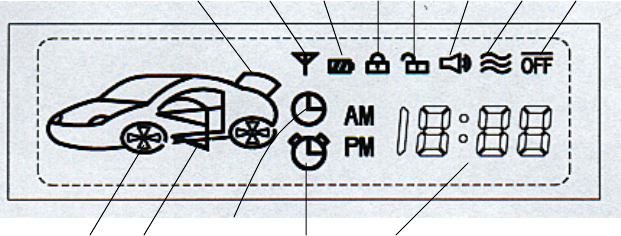
1-2-1. LCD DISPLAY OF PAGER
13 1 2 3 4 5 6 7
8 9 10 11 12
• ANTENNA
• LOW BATTERY INDICATOR
• DOOR LOCK
• DOOR UNLOCK
• ALERT TONE
• VIBRATION
• RF RECEIVING ON/OFF
• CAR SHAPE (WHEN SHOCK-SENSOR IS TRIGGERED, ICON
BLINKING)
• DOOR OPEN
• PARKING ALARM TIMER
• WAKE-UP TIMER
• CLOCK
• TRUNK OPEN
1-2-2. INSERTING BATTERY INTO THE PAGER
•A pager turns on all of LCD icons and backlight with alert
tone and
vibration when the battery (AAA alkaline) is inserted
into the pager.
•Please remove and re-insert the battery when receiver does
not operate
like this.
•The alert tone is repeated five times, but it is stopped
instantly
when any button on the receiver is pressed .
1-2-3. FUNCTION OF BUTTON
•The right button is MODE KEY which is used for the setting
of each
function and time.
•The left button is PARKING KEY whitch is used for parking
timer.
1-2-4. THE USAGE OF MODE KEY
•The receiver enters into the change of MODE with beep tone
when the
MODE KEY is pressed for more then 2 seconds.
•The procedure for the change of MODE is as follows.
• RF RECEIVING ON/OFF
• SELECT OF ALERT TONE or VIBRATION
• ADJUST OF CLOCK
• WAKE-UP ALARM ON/OFF
• ADJUST OF WAKE-UP ALARM TIME
•The left button will be used when the change of MODE is
required.
•When the MODE-KEY is usually pressed shortly, the MODE-
KEY is used
for the display of previous status or reset of current
status.
1-2-5. THE USAGE OF PARKING TIMER
•The receiver enters into change of PARKING TIMER with beep
tone when
the left button is pressed for more then 2 seconds. At
that time, the
clock on the LCD will blank which enables the change of
PARKING TIMER.
•At this mode, the left button is used to increase the hour
or minute
when the icon is blanking and the right button is used to
move the
blinking icon to the right.
•The icon of PARKING TIMER is blanking when the PARKING
TIMER is being
operated The operation of PARKING TIMER is cancelled when
the left
button is pressed for more then 2 seconds during the
operation of
PARKING TIMER.
•The previous PARKING TIMER is memorized in the memory of
the receiver. You can use the previous PARKING TIMER
when you press the left button
for more than 2 seconds.
1-2-6. THE EXCHANGE OF BATTERY
•Please exchange the current battery with new battery
within 2 days
when the icon of low battery on the LCD is turned on.
•The receiver memorizes the CURRENT MODE, ALARM TIME,
PARKING TIME and
ID into the memory of the receiver, but it does not
memorize the
CURRENT TIME. When the battery is exchanged with new
battery, you should re-adjust your clock on the receiver.
The current time will be set to 12:00 when you change the
battery.

1-2-7. RF RECEIVING ON/OFF
•The picture of car on the LCD will disappear when the
receiver is set
to OFF.
•The receiver cannot receive a call when the receiver is
turned OFF or
the ID CODE does not match.
1-2-8. HOW TO LEARN ID
•The receiver enters into the ID LEARLING mode when you
press two buttons for more then 2 seconds simultaneously
and then, it blinks.
“Id”on the LCD. The receiver learns the ID and memorizes
it if the
receiver receives the transmitted signal from tramsmitter
within 30
seconds. The transmitted signal from transmitter can be
generated when
DOOR LOCK, DOOR UNLOCK, TRUNK OPEN, SHOCK SENSOR, DOOR
OPEN is sensed.
When the receiver succeened in ID learning, the receiver
sends triple
Short beep.
1-2-9. THE OPERATION WHEN INSTALLED
1-2-9-1. STANT-ALONE OPERATION
•The transmitter enters into ARM MODE after 30 seconds
when the key is
removed from the key box and the transmitter enters into
DISARM MODE
just after that the car is started by key.
MODE PARAMETER
OPEERATION
OF
TRANSMITTER
LCD DISPLAY
OF RECEIVER
ALERT
TONE/
VIBRATION
DOOR LOCK Instant RF
TX
‘LOCK’ICON SINGLE
BEEP
DOOR UNLOCK Instant RF
TX
‘UNLOCK’ICO
N
DUAL BEEP
TRUNK OPEN
Instant RF
TX
& SIREN
TRUNK OPEN
ALERT TONE
(15 TIMES)
SHOCK
SENSOR
Instant RF
TX
& SIREN
BLINKING OF
CAR SHAPE
ALERT TONE
(15 TIMES)
ARM
MODE
DOOR OPEN
30 second
wait
SIREN/STARTK
ILL
/RF TX
DOOR OPEN ALERT TONE
(15 TIMES)

DOOR LOCK Instant RF
TX
‘LOCK’ICON SINGLE
BEEP
DISAR
M
MODE DOOR UNLOCK Instant RF
TX
‘UNLOCK’ICO
N
DUAL BEEP
1-2-9-2. OPERATION INSTALLED WITH CAR ALARM
•The transmitter enters into ARM MODE if it receives ARM
INPUT from
CAR ALARM and enters into DISARM MODE if it does not
receive
ARM INPUT.
MODE PARAMETER
OPERATION OF
TRANSMITTER
LCD DISPLAY
OF RECEIVER
ALERT
TONE/
VIBRATION
DOOR LOCK Instant RF
TX
‘LOCK’ICON SINGLE
BEEP
DOOR UNLOCK Instant RF
TX
‘UNLOCK’ICO
N
DUAL BEEP
REMOTE
START
Instant RF
TX
BLINKING OF
WHEEL
QUADRUPLE
BEEP
TRUNK OPEN
Instant RF
TX
& SIREN
TRUNK OPEN
ALERT TONE
(15 TIMES)
SHOCK
SENSOR
Instant RF
TX
& SIREN
BLINKING OF
CAR SHAPE
ALERT TONE
(15 TIMES)
ARM
MODE
DOOR OPEN
30 second
wait
SIREN/STARTK
ILL
/RF TX
DOOR OPEN
ALERT TONE
(15 TIMES)
DOOR LOCK Instant RF
TX ‘LOCK’ICON SINGLE
BEEP
DOOR UNLOCK Instant RF
TX
‘UNLOCK’ICO
N
DUAL BEEP
DISAR
M
MODE REMOTE
START
Instant RF
TX
BLINKING OF
WHEEL
QUADRUPLE
BEEP
NOTE : The siren or START-KILL will be stopped instantly
when the
Transmitter enters into DISARM mode.
1-2-10. ARM DELAY MODE
•When the transmitter enters into ARM mode, it has on ARM
DELAY mode
between DISARM mode and ARM mode.
1-2-10-1. STAND-ALONE OPERATION
At the stand-alone operation, the transmitter has a 30
seconds
ARM DELAY.
The door-open and shock sensor do not operate during ARM
DELAY.
1-2-10-2. OPERATION WITH CAR ALARM
The transmitter has a 5 seconds ARM DELAY in this
operation.
The door lock and door unlock will operate during ARM
DELAY.
1-3. INSTALLATION OF TRANSMITTER
1).Please connect all of input wires except BAT+, and then
connect BAT+.
All of inputs should be in the normal condition (Door
closed/Trunk
Closed/Shock sensor not-operated/START-IN not-
operated/Door unlocked)
and then, BAT+ should be applied.
2).Please turn ON/OFF the more then 3 times during 5
seconds after BAT+
being applied, and then, the transmitter memorizes the
condition of
input lines whether it is positive input or negative
input. This
procedure should be done within 20 seconds after BAT+
being applied, otherwise the transmitter fetches the data
from memory after 20 seconds and acts by the data.
3).The ACC input and START-IN (REMOTE START) are always
positive input.
The ARM_INPUT is used to determine whether the
transmitter is operated
STAND-ALONE or operated with CAR ALARM when installed.
4).OPERATION OF TRANSMITTER
• STAND-ALONE OPERATION
The transmitter will be operated STAND-ALONE when the
ARMED-
INPUT is grounded before BAT+ being applied. At this
mode, the
transmitter enters into ARM MODE when ACC INPUT is
removed and it enters into DISARM MODE when ACC INPUT
is applied.
• OPERATION WITH CAR ALARM
The transmitter will be operated with CAR ALARM
when the ARMED-
INPUT is floated or connected to the ARMED-OUTPUT of
CAR ALARM.
At this mode, the transmitter enters into ARM MODE by
ARMED-
OUTPUT being supplied from CAR ALARM.
• OPERATION OF EACH INPUT
When any input is sensed, the transmitter sends RF
signal only
once. But the transmitter does not send RF signal
when the door
or trunk is closed. The operation of each input is
mentioned
on the usage of pager. The transmitter can be used
both STAND-
ALONE and operation with CAR ALARM.
5).The receiver should do ID LEARING, after the transmitter
being
installed. When two keys are pressed simultaneously for
more then 2
seconds, the receiver enters into ID LEARING MODE with
beep tone.
At that time, the receiver shows “Id”on the LCD. If it
receives RF
signal from transmitter, the receiver decodes ID+DATA and
memorizes it
into memory in receiver. When the receiver succeeds in ID
LEARING, the
receiver sounds triple beep tone and ends ID LEARING MODE.
When the receiver does not succeed in ID LEARING for 30
seconds, it
ends the ID LEARING MODE with single long beep.
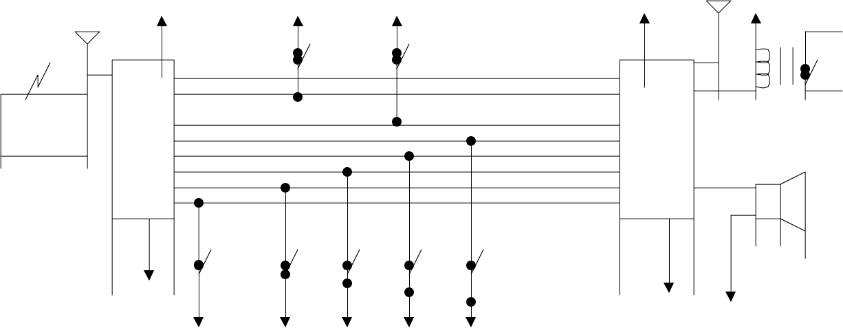
1-3. WIRING DIAGRAM
OPERATION WITH CAR ALARM
B+ B+ RF
B+ B+ ANTENNA B+
ACC ENGINE
IN PUT ON
ACC INPUT ACC INPUT
ENGIN ON INPUT START_IN
REMOTE CAR ARMED OUTPUT ARMED INPUT PAGER START KILL
OUTPUT
CON- ALARM EXTERNAL SHOCK INPUT EXTENAL SHOCK INPUT TRANAS-
TROLLER TRUNK INPUT TRUNK INPUT MITTER
DOOR UNLOCK OUTPUT DOOR UNLOCK INPUT SIREN OUTPUT
DOOR LOCK OUTPUT DOOR LOCK INPUT
DOOR PIN INPUT DOOR PIN INPUT
DOOR DOOR DOOR TRUNK SHOCK
OPEN LOCK UNLOCK OPEN SENSOR
HARNESS A’SSY AND COLOR CODE
1. PIN14 : RED - +12V 2. PIN13 : BROWN - ACC2 3. PIN12 : GREEN – DOOR LOCK
4. PIN11 : BLUE – DOOR UNLOCK 5. PIN10 : VIOLET – START IN 6. PIN9 : GRAY – TRUNK
7. PIN8 : WHITE – SHOCK SENSOR 8. PIN7 : YELLOW – DOOR INPUT 9. PIN6 : LIGHT BLUE – ARMED IN
10. PIN5 : PINK – HORN OUT 11. PIN4 : YELLOW/BLACK – START KILL 12. PIN3 : BLACK - GND
13. PIN2 : NONE 14. PIN1 : NONE
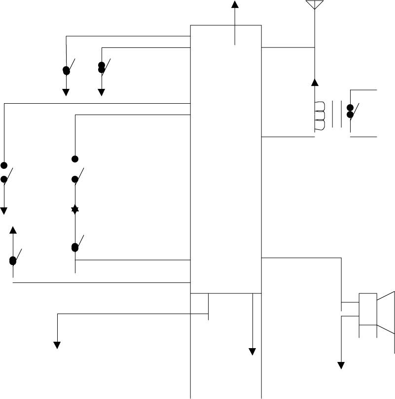
STAND ALONE OPERATION
+12V(B+) ANT
DOOR LOCK INPUT
DOOR UNLOCK INPUT
DOOR DOOR
LOCK UNLOCK B+
DOOR PIN INPUT
TRUNK INPUT MAIN
START KILL
DOOR TX MODULE
OUTPUT
OPEN TRUNK
PIN OPEN
B+
ENGINE
B+ ON
START INPUT
ACC (KEY)
SIREN OUTPU
(ARMED INPUT)
HARNESS A’SSY AND COLOR CODE
1. PIN14 : RED - +12V 2. PIN13 : BROWN – ACC2
3. PIN12 : GREEN – DOOR LOCK 4. PIN11 : BLUE – DOOR UNLOCK
5. PIN10 : VIOLET – START IN 6. PIN9 : GRAY – TRUNK
7. PIN8 : WHITE – SHOCK SENSOR 8. PIN7 : YELLOW – DOOR INPUT
9. PIN6 : LIGHT BLUE – ARMED INPUT 10. PIN5 : PINK – HORN OUT
11. PIN4 : YELLOW/BLACK – START KILL 12. PIN3 : BLACK - GND
13. PIN2: NONE 14. PIN1 : NONE
2. FCC Information
Caution : Any changes or modifications in construction of this device which are not expressly
approved by the party responsible for compliance could void the user's authority to operate
the equipment.
3. FCC Label Information
This device complies with part 15 of the FCC Rules.
Operation is subject to the following two conditions:
(1)This device may not cause harmful interference, and
(2)this device must accept any interference received,
including interference that may cause undesired operation.
DRAKE SYSTEMS
ACE TECHNO 804, YANGPYUNG, YOUNGDEUNGPO , SEOUL 150-103, KOREA
Tel : 82-2-2634-4700 Fax : 82-2-2634-4800
Πριντεδ ιν Κορεα