e DATA AR402 RFID Reader User Manual AR402 manual en V16 2a
e-DATA GmbH RFID Reader AR402 manual en V16 2a
UserManual.wiki
>
e DATA
>
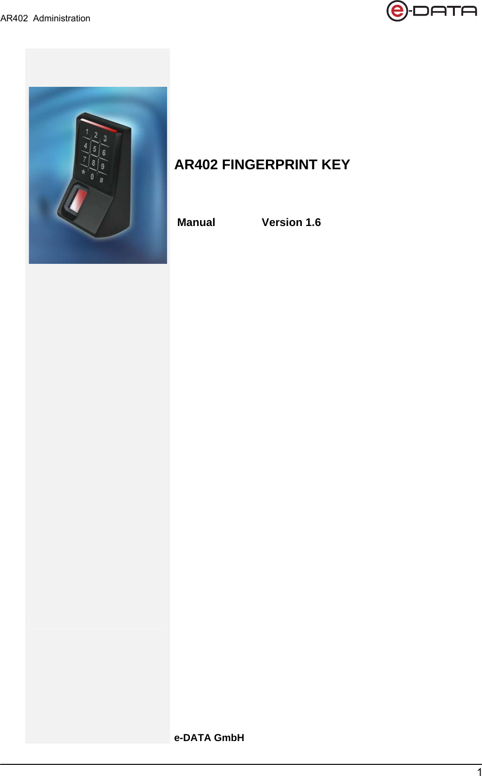
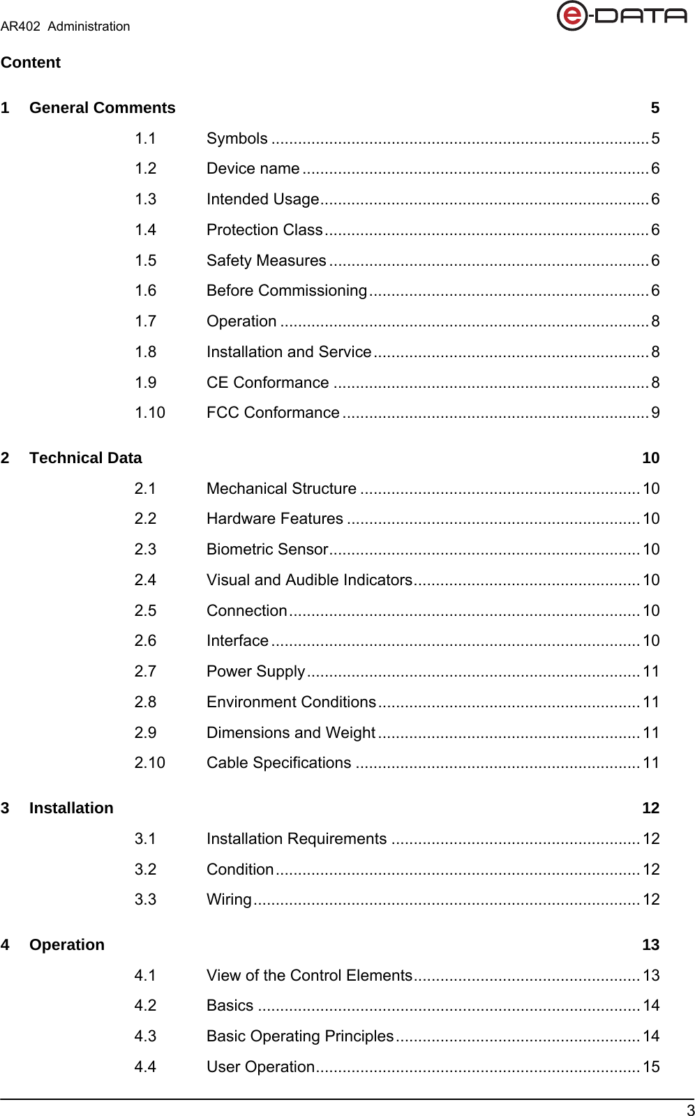
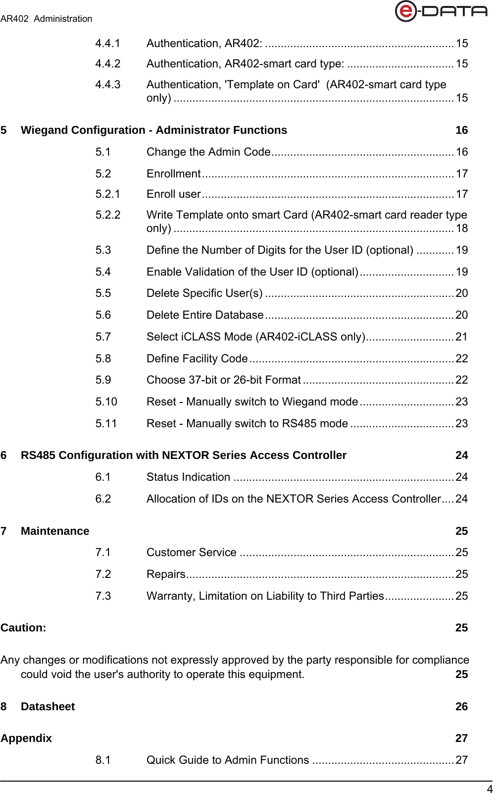
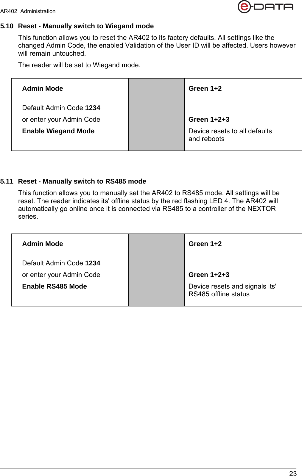
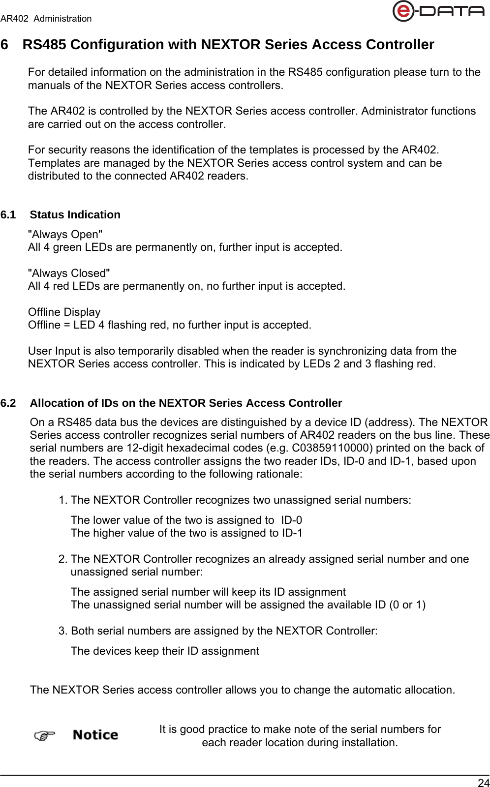
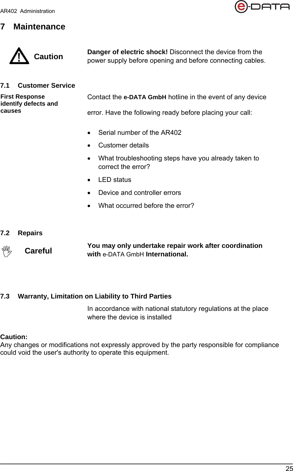
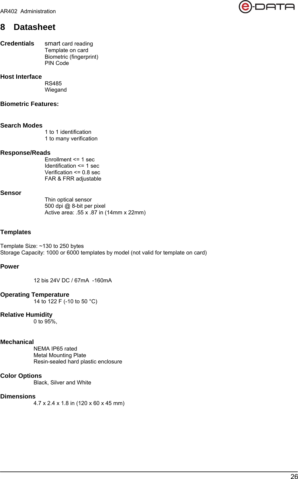
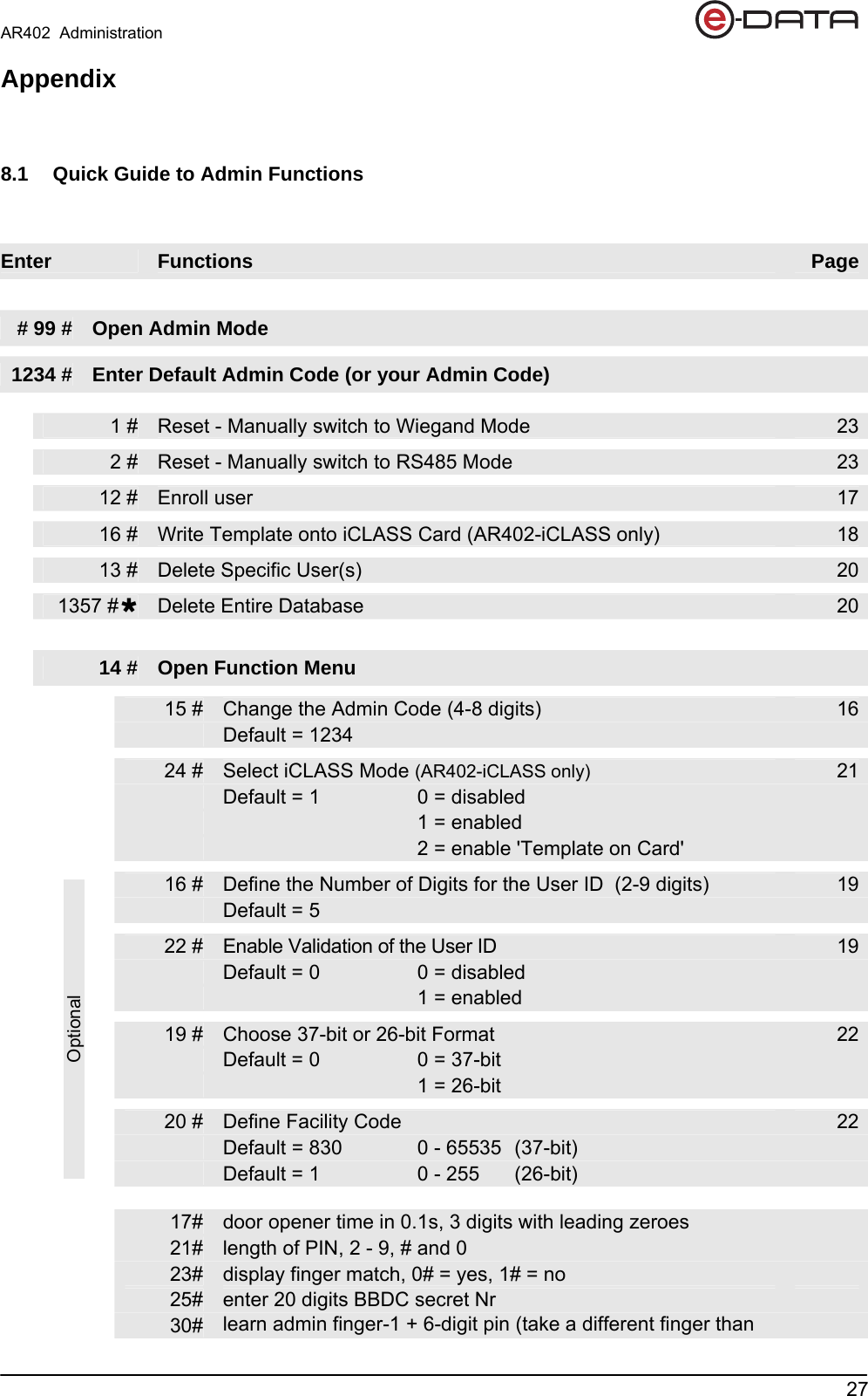
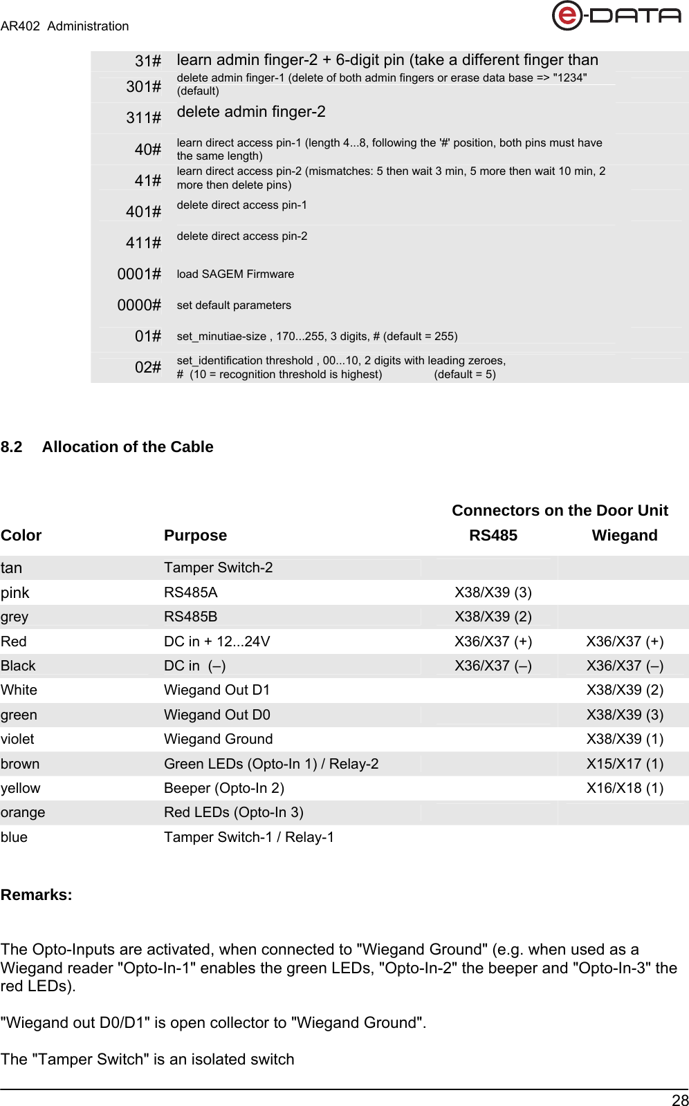
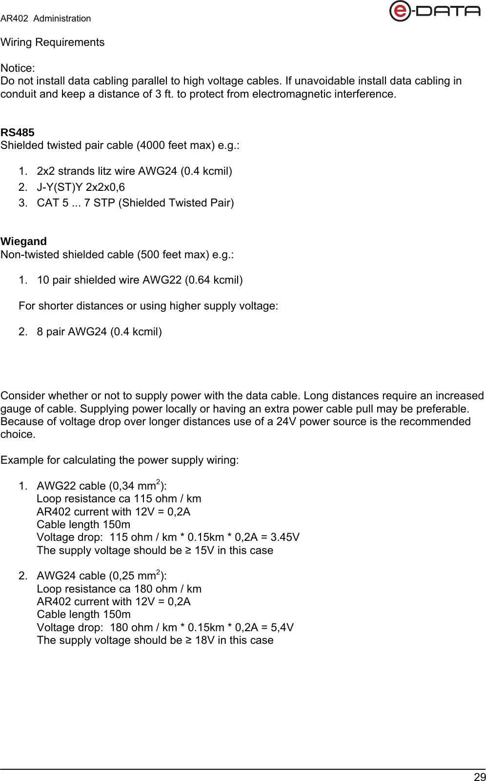
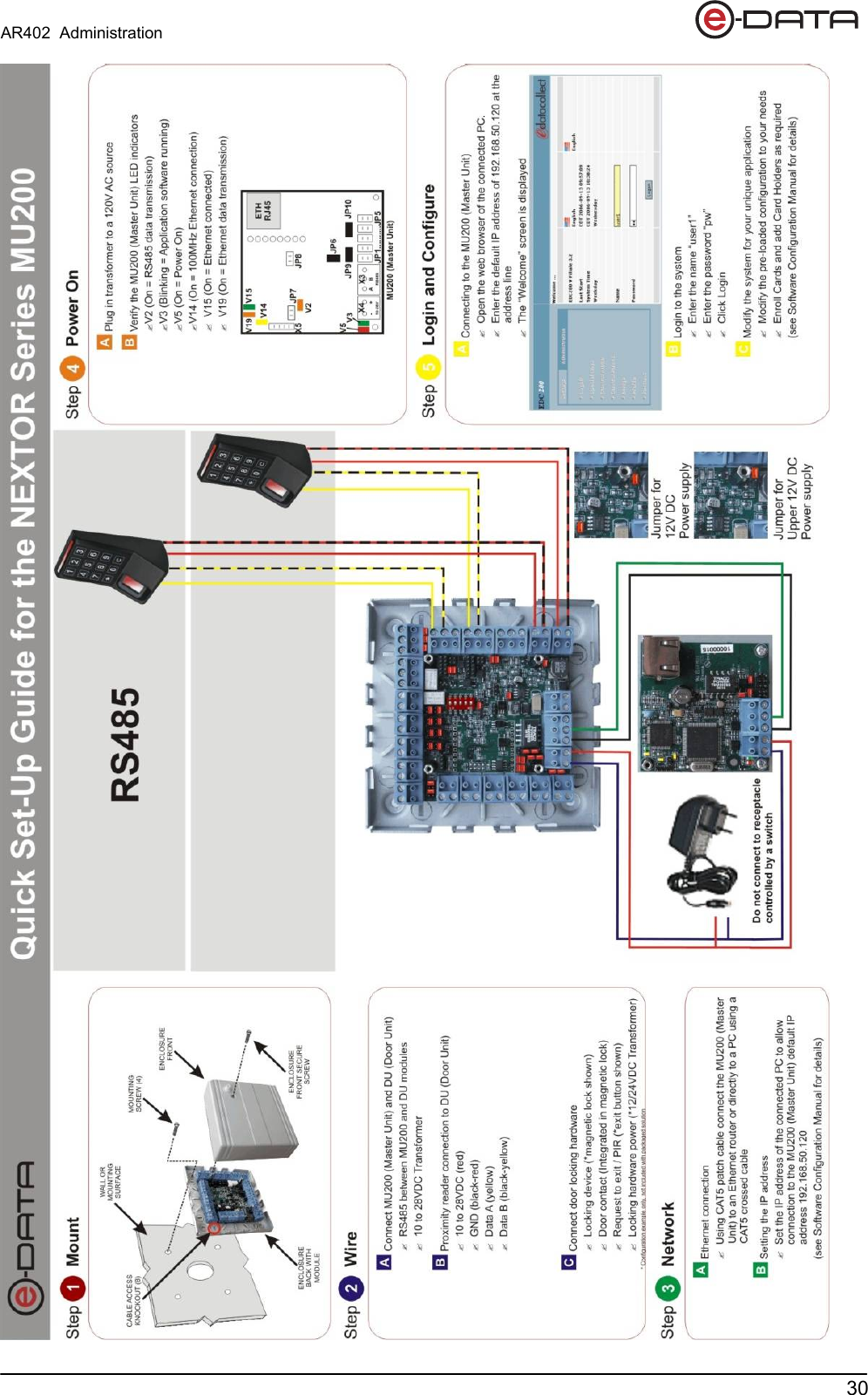
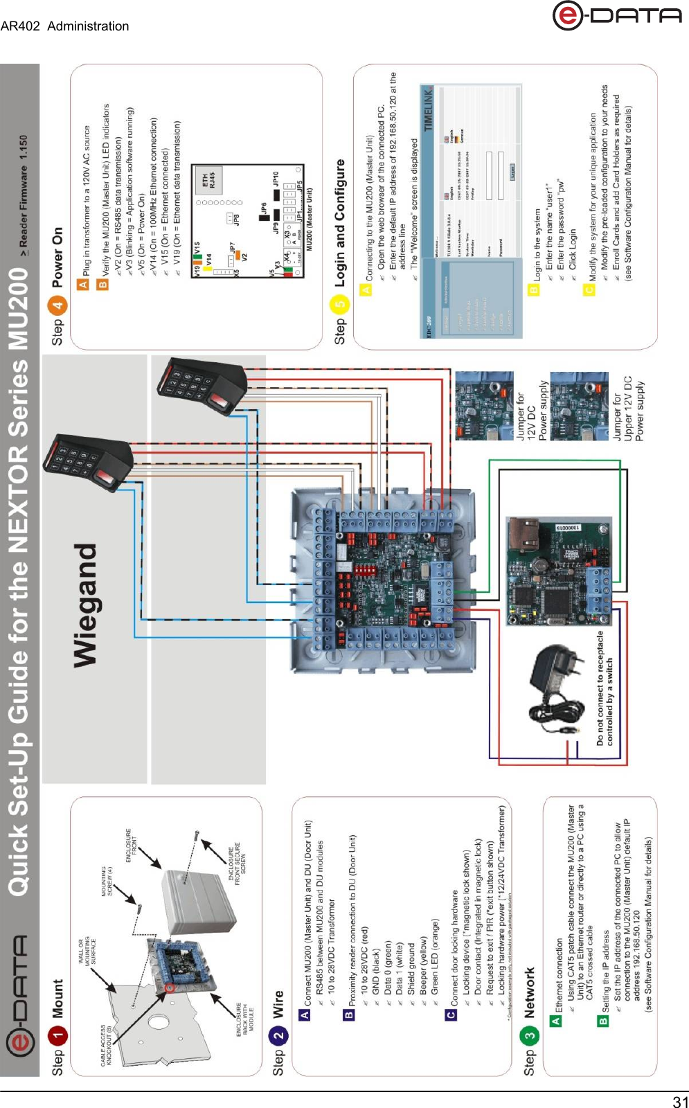
AR402 User Manual
user manual
Navigation menu
Upload a User Manual
Namespaces
Wiki Guide
HTML
PDF
Info
Views
User Manual
Discussion / Help
Navigation