e DATA AR402 RFID Reader User Manual AR402 manual en V16 2a
e-DATA GmbH RFID Reader AR402 manual en V16 2a
e DATA >
user manual
AR402 Administration
1
AR402 FINGERPRINT KEY
Manual Version 1.6
e-DATA GmbH

AR402 Administration
2
e-DATA GmbH
Mollenbachstrasse 19
D-71229 Leonberg
Phone (0 71 52) 93979-0
Fax (0 71 52) 93979-50
info@de.e-DATA.com
AR402 Manual
Version 1.5
Firmware 1.717 or higher
Copyright 2011 e-DATA GmbH
This Manual is protected by copyright. The user manual may only be
copied within the framework of the intended usage. Any reproduction
or translations of the manual beyond this or its transmission onto
electronic media, even in extract form, is only allowed with the
express permission of e-DATA GmbH.
e-DATA GmbH reserves the right to make changes to the user
manual and to the devices without special notice.
e-DATA GmbH does not accept any liability whatsoever for direct or
indirect damage, especially loss of data, that results from the usage of
the AR402 terminal, or from the information in this Manual

AR402 Administration
3
Content
1 General Comments 5
1.1 Symbols .....................................................................................5
1.2 Device name ..............................................................................6
1.3 Intended Usage..........................................................................6
1.4 Protection Class.........................................................................6
1.5 Safety Measures ........................................................................ 6
1.6 Before Commissioning............................................................... 6
1.7 Operation ...................................................................................8
1.8 Installation and Service.............................................................. 8
1.9 CE Conformance .......................................................................8
1.10 FCC Conformance ..................................................................... 9
2 Technical Data 10
2.1 Mechanical Structure ...............................................................10
2.2 Hardware Features ..................................................................10
2.3 Biometric Sensor...................................................................... 10
2.4 Visual and Audible Indicators...................................................10
2.5 Connection...............................................................................10
2.6 Interface ................................................................................... 10
2.7 Power Supply........................................................................... 11
2.8 Environment Conditions........................................................... 11
2.9 Dimensions and Weight ...........................................................11
2.10 Cable Specifications ................................................................11
3 Installation 12
3.1 Installation Requirements ........................................................12
3.2 Condition..................................................................................12
3.3 Wiring.......................................................................................12
4 Operation 13
4.1 View of the Control Elements................................................... 13
4.2 Basics ......................................................................................14
4.3 Basic Operating Principles....................................................... 14
4.4 User Operation......................................................................... 15

AR402 Administration
4
4.4.1 Authentication, AR402: ............................................................15
4.4.2 Authentication, AR402-smart card type: .................................. 15
4.4.3 Authentication, 'Template on Card' (AR402-smart card type
only) .........................................................................................15
5 Wiegand Configuration - Administrator Functions 16
5.1 Change the Admin Code.......................................................... 16
5.2 Enrollment................................................................................ 17
5.2.1 Enroll user................................................................................17
5.2.2 Write Template onto smart Card (AR402-smart card reader type
only) .........................................................................................18
5.3 Define the Number of Digits for the User ID (optional) ............19
5.4 Enable Validation of the User ID (optional).............................. 19
5.5 Delete Specific User(s) ............................................................20
5.6 Delete Entire Database............................................................ 20
5.7 Select iCLASS Mode (AR402-iCLASS only)............................ 21
5.8 Define Facility Code................................................................. 22
5.9 Choose 37-bit or 26-bit Format ................................................ 22
5.10 Reset - Manually switch to Wiegand mode.............................. 23
5.11 Reset - Manually switch to RS485 mode ................................. 23
6 RS485 Configuration with NEXTOR Series Access Controller 24
6.1 Status Indication ......................................................................24
6.2 Allocation of IDs on the NEXTOR Series Access Controller.... 24
7 Maintenance 25
7.1 Customer Service ....................................................................25
7.2 Repairs.....................................................................................25
7.3 Warranty, Limitation on Liability to Third Parties...................... 25
Caution: 25
Any changes or modifications not expressly approved by the party responsible for compliance
could void the user's authority to operate this equipment. 25
8 Datasheet 26
Appendix 27
8.1 Quick Guide to Admin Functions .............................................27
AR402 Administration
5
8.2 Allocation of the Cable .............................................................28
1 General Comments
1.1 Symbols
The following symbols have been used in this manual:
Helpful tips and special characteristics of the AR402.
Careful
Possible danger, which – if the warning is not observed – can
result in damage to property, or slight to moderate bodily injury.
Caution
Possible danger, which - if the warning is not observed - can
result in death or serious bodily injury.

AR402 Administration
6
1.2 Device description
This device exists to identify persons by means of their
fingerprints and / or the contents of a smart card and / or a
personal number to be entered.
The human interface is implemented by a keyboard and a
beeper and several multicoloured Leds.
The device is connected to superordinated data processing
systems by a RS485 data line
1.3 Device name
This manual outlines the AR402 and the supported functions.
1.4 Intended Usage
The device may only be used under conditions and for
purposes for which it has been designed.
(See Chapter Environment Conditions)
1.5 Protection Class
The device conforms to the conditions of protection class IP65.
Protection class III EN60950-1.
Protection class IP65 DIN EN 60529
1.6 Safety Measures
The device has been built according to the current and
recognized technical safety rules EN60950-1 and left our
manufacturing facility in perfect condition. Improper handling
and operation outside the specified conditions can result in
dangers due to electrical current. This can endanger the lives of
persons and damage the device.
1.7 Before Commissioning
Inspect the device for visible damage resulting from shipment
or improper storage. Do not commission a damaged device.
Careful
The device may only be operated with DC voltage 12 to 24V DC.
The device is protected against polarity reversal.

AR402 Administration
7

AR402 Administration
8
1.8 Operation
Do not subject the device to any mechanical stresses such as
impacts, violent shaking or heavy loads. Impacts and shaking
can damage the electronics.
1.9 Installation and Service
The device may only be opened by trained specialists.
Disconnect the device from the power source before opening.
• You may only perform repairs in collaboration with e-
DATA GmbH.
1.10 CE Conformance
This device is manufactured according to the safety
requirements of EN 60950.
Safety of electrical equipment
• European Norm EN 60950
This device complies with interference resistance criteria
according to EN 55022; EN 61000-3-2/-3; EN 55024

AR402 Administration
9
1.11 FCC Conformance
This device complies with interference resistance criteria
according to FCC Rules 47 CFR Part 15 – Subpart C Section
15.209
NOTE: This equipment has been tested and
found to comply with the limits for a Class B
digital device, pursuant to part 15 of the FCC
Rules. These limits are designed to provide
reasonable protection against harmful
interference in a residential installation. This
equipment generates, uses and can radiate
radio frequency energy and, if not installed and
used in accordance with the instructions, may
cause harmful interference to radio
communications. However, there is no guarantee
that interference will not occur in a particular
installation. If this equipment does cause harmful
interference to radio or television reception,
which can be determined by turning the
equipment off and on, the user is encouraged to
try to correct the interference by one or more of
the following measures:
— Reorient or relocate the receiving antenna.
— Increase the separation between the
equipment and receiver.
— Connect the equipment into an outlet on a
circuit different from that to which the
receiver is connected.
— Consult the dealer or an experienced
radio/TV technician for help.

AR402 Administration
10
2 Technical Data
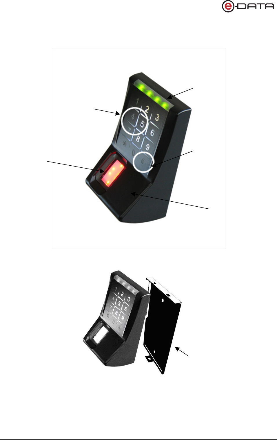
2.1 Mechanical Structure
• Plastic body + metal wall mount panel
• Resin sealed electronics
• 12 inch cable molded into body
2.2 Hardware Features
• Fingerprint biometric sensor
• MIFARE,DESFire,iCLASS- reader
• 12-key Keypad
• Beeper
• 4 red/green LEDs
• Keyboard illumination
• 3 Opto-Inputs
• Wiegand output
• RS485 host interface
2.3 Biometric Sensor
• Thin optical sensor
• 500 dpi @ 8 bit per pixel
• Active area: 0,5 x 0,9 in
• Template size: 130...250 bytes
• Memory: 1000 templates (optionally 6000)
2.4 Visual and Audible Indicators
• 4 red/green LED user interface
• Beeper (3khz)
2.5 Connection
• Cable with 11 circuits
2.6 Interface
• RS485 interface, 19200 Baud (8/N/1)
• Wiegand Output
• 3 Opto-inputs, active

AR402 Administration
11
2.7 Power Supply
• DC Voltage, 12...24V
Minimum 1A and complying with Limited Power Source
according to IEC/EN 60950-1
• Power consumption max 5W
• CSA or UL listing is recommended
2.8 Environment Conditions
• Temperature range 14° to 122º F
• Indoor and Outdoor
• Protection class IP65
2.9 Dimensions and Weight
• 4,5 in x 2,5 in x 2 in (H x W x D)
• Approx. 0.4 lb
2.10 Cable Specifications
• RS485
Shielded twisted pair cable (4000 feet max)
Examples:
1. 2x2 strands litz wire AWG24 (0.4 kcmil)
2. J-Y(ST)Y 2x2x0,6
3. CAT 5 ... 7 STP (Shielded Twisted Pair)
• Wiegand
Non-twisted shielded cable (500 feet max)
Examples:
1. 10 pair shielded wire AWG22 (0.64 kcmil)
For shorter distances or using higher supply voltage:
2. 8 pair AWG24 (0.4 kcmil)

AR402 Administration
12
3 Installation
3.1 Installation Requirements
For outdoor use, determine an appropriate place for mounting
the AR402. Avoid mounting in direct sunlight as this may affect
the function of the biometric sensor.
Direct sunlight may overheat the AR402.
3.2 Condition
Check the following for mounting the AR402
Device needs proper clearance.
A
ll cabling must be provided, electrical cable, data cable and
door opener cabling.
Power supply is provided.
3.3 Wiring
Do not install data cables parallel to cables conducting high
voltage. If unavoidable, install the data cables in conduit and
keep them at a distance of 1 yd to protect them against
electromagnetic interference.
AR402 Administration
13
4 Operation
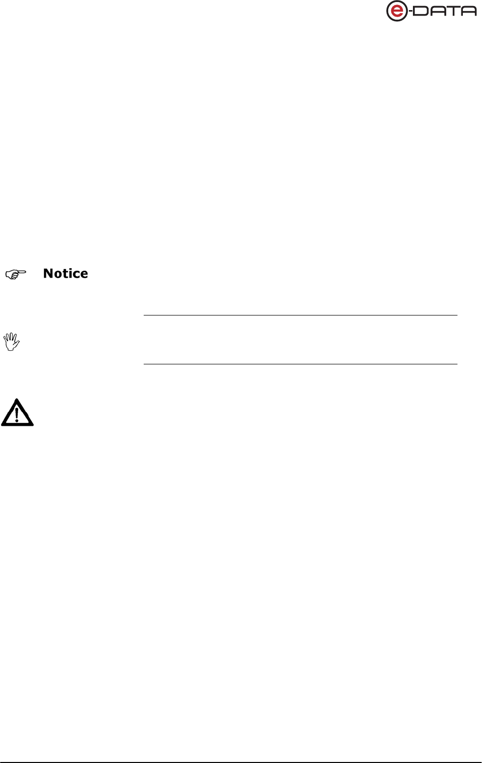
4.1 View of the Control Elements
LEDs green / red
1-2-3-4
Execute Button #
Fingerprint Sensor
Keypad
Wall Mount Panel
A
ntenna to read smart
cards

AR402 Administration
14
4.2 Basics
The AR402 is manufactured in two versions:
1. AR402 with built-in biometrical sensor and keypad
2. AR402-Card Reader with built-in biometrical sensor and keypad + embedded smart card
reader
The AR402 identifies authorized users by scanning their fingerprints (and optionally their
PINs and smart cards). Successful identification sends a trigger signal to an access
controller within a protected area and is followed by a door lock or release.
The AR402-Card Reader reads fingerprints and smart cards alternatively.
Fingerprint authentication requires that the authorized user's fingerprints have been enrolled
in advance and that they have been linked to a unique User ID.
Enrollment can be performed on the AR402, which stores the collected data (Templates).
The 'Template on Card' mode allows you to write Templates onto smart cards (currently
16k2 cards only).
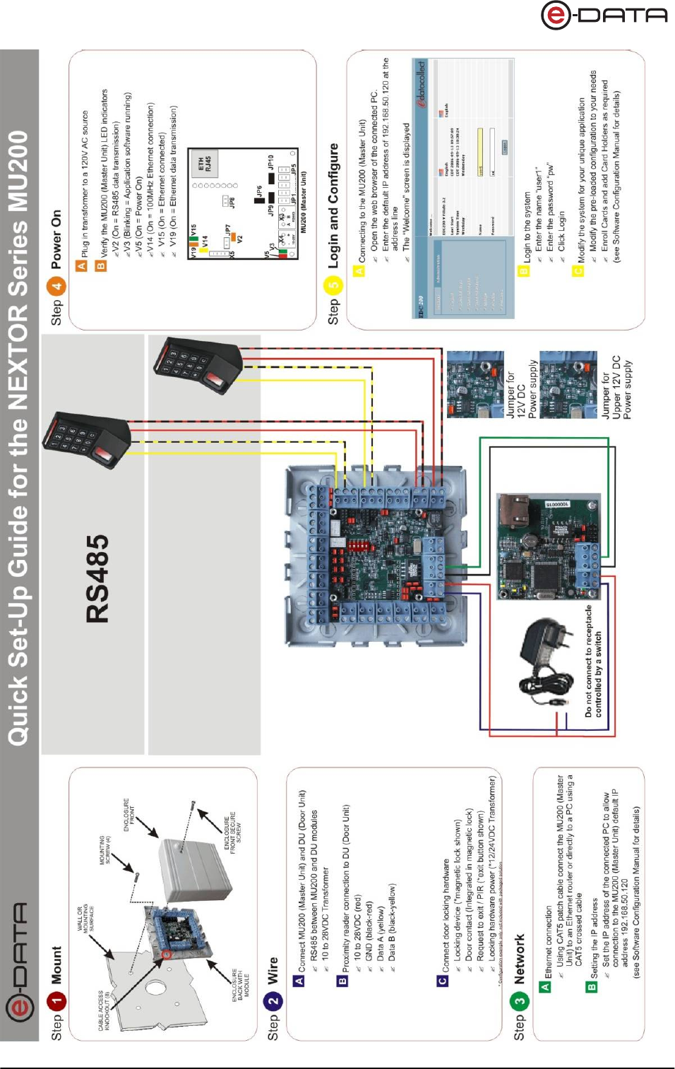
The AR402 can either be run using the RS485 interface or the Wiegand output:
RS485 Configuration Running the reader using the RS485 interface means that
administration of the AR402 is done on the NEXTOR Series
access controller.
All administrator functions, except for enrollment, are disabled
on the AR402.
Fingerprint Templates are managed by the access controller
and can be distributed to the connected AR402 readers.
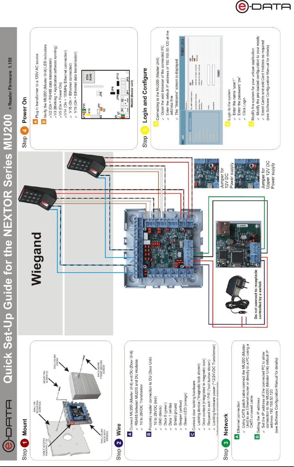
Wiegand Configuration All administrator functions described in this manual, except for
enrollment, only apply to the Wiegand configuration. All settings
are entered on the keypad of the AR402.
Fingerprint templates are stored on the AR402 and cannot be
distributed to connected AR402 readers.
4.3 Basic Operating Principles
General Pressing any key triggers a beep.
Release Beep tone and all LEDs flashing green
Green and Red / Green LEDs Guides an administrator through the setup menus
Red LEDs and Beeps Generally indicates an error
Error Message 3 short beeps and all LEDs flashing red 3 times indicate an error.
The desired function was not performed.
3x Key "#" Press "#" three times to reset the reader to keypad default state after typing
errors or wait for timeout (10-30 seconds, depending on status) to return to the default
position.

AR402 Administration
15
4.4 User Operation
4.4.1 Authentication, AR402:
Authorized users who's fingers have been enrolled and who's PIN have been registered are
granted access when entering:
Finger without PIN: Press » => Bio-Sensor is illuminated
Apply Finger => Green LEDs (Access granted)
Finger plus PIN: Press » => Bio-Sensor is illuminated
(Wiegand) Apply Finger => LEDs flash (Waiting for PIN entry)
Enter PIN => Green LEDs (Access granted)
Finger plus PIN: Press » => Green and Red LEDs 1 and 4 flash (Waiting for PIN entry)
(RS485) Enter PIN => Bio-Sensor is illuminated
Apply Finger => Green LEDs (Access granted)
4.4.2 Authentication, AR402-smart card type:
Authorized users who's fingers have been enrolled and who's card type cards and PIN have been
registered on the access controller are granted access when entering:
Finger: as above
Card without PIN: smart card => Beep and short green signal (Indication card was read)
=> Green LEDs (Access granted)
Card plus PIN: smart card => Beep and short green signal (Indication card was read)
(Wiegand) => LEDs flash (Waiting for PIN entry)
Enter PIN => Green LEDs (Access granted)
Card plus PIN: smart card => Beep and short green signal (LEDs 2/3) (Indication card was read)
(RS485) => Green and Red LEDs 1 and 4 flash (Waiting for PIN entry)
Enter PIN => Green LEDs (Access granted)
4.4.3 Authentication, 'Template on Card' (AR402-smart card type only)
Authorized users who's fingers have been stored onto their card and who's smart cards and PIN
have been registered on the access controller are granted access when entering:
Card without PIN: smart card => LEDs flash green.
Beep when finished reading the card (Indication card was read)
=> Green LEDs (Access granted)
Card plus PIN: smart card => LEDs flash green.
Beep when finished reading the card (Indication card was read)
=> LEDs flash (Waiting for PIN entry)
Enter PIN => Green LEDs (Access granted)
The AR402-smart card type reads fingers and smart cards alternatively without having to switch
between operating modes.
If a mistype occurs on the keypad simply press the “#” three times to reset and start over.
The various operating modes are configured in the administrator’s menu as described in section 5.

AR402 Administration
16
5 Wiegand Configuration - Administrator Functions
With the exception of enrollment all administrator functions described in this section only
apply to the Wiegand configuration, i.e. connecting the AR402 to the access controller via
Wiegand.
Administration of the AR402 with Wiegand is done on the reader. The Fingerprint Key user
interface is comprised of the keypad, fingerprint reader and smart reader as input devices
and the LEDs and beeper as output devices.
The administrator functions allow administrators to configure the operating modes and the
Admin code.
e-DATA GmbH delivers the device with the default Admin Code '1234'.
In addition to the Admin Code each device has a fixed access code. This code corresponds
with the device’s serial number, a 12-digit hexadecimal code, which is printed on the back of
the reader. The 12-digit code serves as a basis for calculating the access code if your
Admin Code is lost. In this case please contact e-DATA GmbH.
5.1 Change the Admin Code
The default Admin Code is '1234'.
For security reasons it is advisable to change the Admin Code!
The Admin Code can be a 4-digit to 8-digit code.
Admin Mode # 99 # Green 1+2
Default Admin Code 1234
or enter your Admin Code xxxx # Green 1+2+3
Function Menu 14 # Green 1+2 flashing Beep
Change Admin Code 15 # Green 2+3 flashing Beep
(Default = 1234) 4 - 8 digits # Green 1+2 flashing Beep
Finalize by 3 x # ###
or wait for Timeout
For security reasons the default Admin Code
should be chan
g
ed.
(
see below
)

AR402 Administration
17
5.2 Enrollment
The AR402 assigns 2 different fingers (e.g. left index finger, right index finger) to the unique
User ID of a person. Each of the 2 fingers must be scanned 3 times by the Fingerprint Key
reader. The biometric sensor reads fingers best when placing your finger on the sensor with
some pressure.
3 x + 3 x
5.2.1 Enroll user
The fingers of a new user are enrolled by entering the following on the reader's keypad:
Admin Mode # 99 # Green 1+2
Default Admin Code 1234
or enter your Admin Code xxxx # Green 1+2+3
Enter Enrollment Code 12 # Green 1+2+3+4 flashing
Enter User ID * xxxxx # Green 1 flashing Sensor Red
Apply 2 Fingers 3x if successful:
Green 1+2+3+4 flashing
Finalize by 1 x # #
or wait for Timeout
Entering a User ID with an incorrect number of digits, an already existing User ID, or variant
IDs with Validation enabled and also if your fingers already have been scanned will prompt
an error message (all red LEDs flashing three times) and cause the reader to return to it's
default position.
* With Validation enabled enter your User ID a second time. After the first entry of your User
ID and the '#' key, the four green quickly flashing LEDs indicate the reader to expect your
User ID for a second time.
Bright daylight may affect the function of the biometric sensor.
Shadowing the sensor with your hand will help.

AR402 Administration
18
5.2.2 Write Template onto smart Card (AR402-smart card reader type only)
Setting the reader to 'Template on Card' is required for this operation (see "Choose
iCLASS Mode", page 21) and the reader must 'know' the encryption of your iCLASS cards.
The 'Template on Card' mode does not store fingerprint templates to the AR402 but writes
them onto iCLASS cards instead. The reader identifies authorized users by comparing the
fingerprint templates stored on the card with the scanned finger of the card holder. If the
two match the reader will send the facility code and card number to the controller.
'Template on Card' may be expedient where storing biometric data is prohibited. In
addition this mode offers a good alternative using biometric readers in a Wiegand
configuration as users will not have to enroll on multiple readers.
At this point 'Template on Card' only works with 16K2 iCLASS cards and in a Wiegand
configuration.
The AR402-iCLASS will store the fingers of a new user onto iCLASS cards when entering
the following on the keypad:
Admin Mode # 99 # Green 1+2
Default Admin Code 1234
or enter your Admin Code xxxx # Green 1+2+3
Enter Enrollment Code 16 # Green 1 flashing Sensor Red
Apply 2 Fingers 3x if successful:
Green 1+2+3+4 flashing
Apply Card
until the writing process is completed Green 1 flashing Sensor Red
Enroll next finger or
Finalize by 3 x # ###
or wait for Timeout
AR402 Administration
19
5.3 Define the Number of Digits for the User ID (optional)
Here the length of the User IDs (Default = 5 digits) can be set to a value between 2 and 9
digits.
In the process of enrollment User IDs need to be entered as a personal and unique ID.
Admin Mode # 99 # Green 1+2
Default Admin Code 1234
or enter your Admin Code xxxx # Green 1+2+3
Function Menu 14 # Green 1+2 flashing Beep
Number of Digits for User ID 16 # Green 3+4 flashing Beep
(Default = 5) 2 - 9 digits # if successful:
Green 1+2 flashing Beep
Finalize by 3 x # ###
or wait for Timeout
5.4 Enable Validation of the User ID (optional)
This menu allows you to enable the validation of the User ID for enrollment to eliminate
incorrect entries.
Admin Mode # 99 # Green 1+2
Default Admin Code 1234
or enter your Admin Code xxxx # Green 1+2+3
Function Menu 14 # Green 1+2 flashing Beep
Validation of User ID 22 # Green 3+4 flashing Beep
Enable 1 # Green 1+2 flashing Beep
or Disable (Default) 0 # Green 1+2 flashing Beep
Finalize by 3 x # ###
or wait for Timeout
AR402 Administration
20
5.5 Delete Specific User(s)
This function allows you to remove a single user (User ID with its fingerprints) or several
users of your choice from memory.
Admin Mode # 99 # Green 1+2
Default Admin Code 1234
or enter your Admin Code xxxx # Green 1+2+3
Delete Specific User(s) 13 # Green 1+2+3+4 flashing
User ID xxxxx # if successful:
Green 1+2+3+4 flashing Beep
Optional: More User IDs xxxxx # Green 1+2+3+4 flashing Beep
Finalize by 3 x # ###
or wait for Timeout
5.6 Delete Entire Database
Caution
Admin Mode # 99 # Green 1+2
Default Admin Code 1234
or enter your Admin Code xxxx # Green 1+2+3
Enter Delete Database 1357 # Red 1+2+3+4 flashing Beep
Press » key to confirm » if successful:
Green 1+2+3 Beep
Finalize by 3 x # ###
or wait for Timeout
If you see red LEDs after pressing » this indicates the database was not deleted and the
procedure needs to be repeated.
This function deletes all users of the reader's database!

AR402 Administration
21
5.7 Select iCLASS Mode (AR402-iCLASS only)
In its default setting the iCLASS mode is activated on AR402-iCLASS readers. This mode
reads fingerprints and iCLASS cards alternatively.
This menu allows you to disable the iCLASS module or to enable the 'Template on Card'
mode instead (cp. "Enrollment with 'Template on Card' enabled, page 18).
Admin Mode # 99 # Green 1+2
Default Admin Code 1234
or enter your Admin Code xxxx # Green 1+2+3
Function Menu 14 # Green 1+2 flashing Beep
iCLASS Menu 24 # Green 3+4 flashing Beep
Enable iCLASS (Default) 1 # Green 1+2 flashing Beep
or Enable 'Template on Card' 2 # Green 1+2 flashing Beep
or Disable iCLASS 0 # Green 1+2 flashing Beep
Finalize by 3 x # ###
or wait for Timeout
AR402 Administration
22
5.8 Define Facility Code
These settings only apply to the trigger signal of the reader's biometric sensor sent to the
access controller. The Facility Code of iCLASS cards is sent to the access controller
untouched and independent of these settings.
In a Wiegand configuration you can set the Facility Code of the biometric sensor according
to your requirements. The Default Facility Code for 37-bit is '830'.
Admin Mode # 99 # Green 1+2
Default Admin Code 1234
or enter your Admin Code xxxx # Green 1+2+3
Function Menu 14 # Green 1+2 flashing Beep
Define Facility Code 20 # Green 3+4 flashing Beep
1 – 5 digits # Green 1+2 flashing Beep
37-bit (Default = 830) 0 … 65535 #
26-bit (Default = 1) 0 … 255 #
Finalize by 3 x # ###
or wait for Timeout
Caution
5.9 Choose 37-bit or 26-bit Format
These settings only apply to the trigger signal of the reader's biometric sensor sent to the
access controller. The Facility Code of iCLASS cards is sent to the access controller
untouched and independent of these settings.
In a Wiegand configuration the format of the biometric sensor's trigger signal to the access
controller can be defined (e.g. Set the biometric sensor's format to the 26-bit format if HID
cards with 26-bit standard format are used).
Admin Mode # 99 # Green 1+2
Default Admin Code 1234
or enter your Admin Code xxxx # Green 1+2+3
Function Menu 14 # Green 1+2 flashing Beep
Choose Format 19 # Green 3+4 flashing Beep
37-bit with Facility Code 0 # Green 1+2 flashing Beep
(Default)
26-bit with Facility Code 1 # Green 1+2 flashing Beep
Finalize by 3 x # ###
or wait for Timeout
If both fingers and iCLASS cards are employed in a Wiegand
configuration your range of fingerprint User IDs must not overlap
with your range of card numbers!

AR402 Administration
23
5.10 Reset - Manually switch to Wiegand mode
This function allows you to reset the AR402 to its factory defaults. All settings like the
changed Admin Code, the enabled Validation of the User ID will be affected. Users however
will remain untouched.
The reader will be set to Wiegand mode.
Admin Mode # 99 # Green 1+2
Default Admin Code 1234
or enter your Admin Code xxxx # Green 1+2+3
Enable Wiegand Mode 1 # Device resets to all defaults
and reboots
5.11 Reset - Manually switch to RS485 mode
This function allows you to manually set the AR402 to RS485 mode. All settings will be
reset. The reader indicates its' offline status by the red flashing LED 4. The AR402 will
automatically go online once it is connected via RS485 to a controller of the NEXTOR
series.
Admin Mode # 99 # Green 1+2
Default Admin Code 1234
or enter your Admin Code xxxx # Green 1+2+3
Enable RS485 Mode 2 # Device resets and signals its'
RS485 offline status

AR402 Administration
24
6 RS485 Configuration with NEXTOR Series Access Controller
For detailed information on the administration in the RS485 configuration please turn to the
manuals of the NEXTOR Series access controllers.
The AR402 is controlled by the NEXTOR Series access controller. Administrator functions
are carried out on the access controller.
For security reasons the identification of the templates is processed by the AR402.
Templates are managed by the NEXTOR Series access control system and can be
distributed to the connected AR402 readers.
6.1 Status Indication
"Always Open"
All 4 green LEDs are permanently on, further input is accepted.
"Always Closed"
All 4 red LEDs are permanently on, no further input is accepted.
Offline Display
Offline = LED 4 flashing red, no further input is accepted.
User Input is also temporarily disabled when the reader is synchronizing data from the
NEXTOR Series access controller. This is indicated by LEDs 2 and 3 flashing red.
6.2 Allocation of IDs on the NEXTOR Series Access Controller
On a RS485 data bus the devices are distinguished by a device ID (address). The NEXTOR
Series access controller recognizes serial numbers of AR402 readers on the bus line. These
serial numbers are 12-digit hexadecimal codes (e.g. C03859110000) printed on the back of
the readers. The access controller assigns the two reader IDs, ID-0 and ID-1, based upon
the serial numbers according to the following rationale:
1. The NEXTOR Controller recognizes two unassigned serial numbers:
The lower value of the two is assigned to ID-0
The higher value of the two is assigned to ID-1
2. The NEXTOR Controller recognizes an already assigned serial number and one
unassigned serial number:
The assigned serial number will keep its ID assignment
The unassigned serial number will be assigned the available ID (0 or 1)
3. Both serial numbers are assigned by the NEXTOR Controller:
The devices keep their ID assignment
The NEXTOR Series access controller allows you to change the automatic allocation.
It is good practice to make note of the serial numbers for
each reader location during installation.

AR402 Administration
25
7 Maintenance
Caution
Danger of electric shock! Disconnect the device from the
power supply before opening and before connecting cables.
7.1 Customer Service
First Response
identify defects and
causes
Contact the e-DATA GmbH hotline in the event of any device
error. Have the following ready before placing your call:
• Serial number of the AR402
• Customer details
• What troubleshooting steps have you already taken to
correct the error?
• LED status
• Device and controller errors
• What occurred before the error?
7.2 Repairs
Careful
You may only undertake repair work after coordination
with e-DATA GmbH International.
7.3 Warranty, Limitation on Liability to Third Parties
In accordance with national statutory regulations at the place
where the device is installed
Caution:
Any changes or modifications not expressly approved by the party responsible for compliance
could void the user's authority to operate this equipment.

AR402 Administration
26
8 Datasheet
Credentials smart card reading
Template on card
Biometric (fingerprint)
PIN Code
Host Interface
RS485
Wiegand
Biometric Features:
Search Modes
1 to 1 identification
1 to many verification
Response/Reads
Enrollment <= 1 sec
Identification <= 1 sec
Verification <= 0.8 sec
FAR & FRR adjustable
Sensor
Thin optical sensor
500 dpi @ 8-bit per pixel
Active area: .55 x .87 in (14mm x 22mm)
Templates
Template Size: ~130 to 250 bytes
Storage Capacity: 1000 or 6000 templates by model (not valid for template on card)
Power
12 bis 24V DC / 67mA -160mA
Operating Temperature
14 to 122 F (-10 to 50 °C)
Relative Humidity
0 to 95%,
Mechanical
NEMA IP65 rated
Metal Mounting Plate
Resin-sealed hard plastic enclosure
Color Options
Black, Silver and White
Dimensions
4.7 x 2.4 x 1.8 in (120 x 60 x 45 mm)

AR402 Administration
27
Appendix
8.1 Quick Guide to Admin Functions
Enter Functions Page
# 99 # Open Admin Mode
1234 # Enter Default Admin Code (or your Admin Code)
1 # Reset - Manually switch to Wiegand Mode 23
2 # Reset - Manually switch to RS485 Mode 23
12 # Enroll user 17
16 # Write Template onto iCLASS Card (AR402-iCLASS only) 18
13 # Delete Specific User(s) 20
1357 # » Delete Entire Database 20
14 # Open Function Menu
15 # Change the Admin Code (4-8 digits) 16
Default = 1234
24 # Select iCLASS Mode (AR402-iCLASS only) 21
Default = 1 0 = disabled
1 = enabled
2 = enable 'Template on Card'
16 # Define the Number of Digits for the User ID (2-9 digits) 19
Default = 5
22 # Enable Validation of the User ID 19
Default = 0 0 = disabled
1 = enabled
19 # Choose 37-bit or 26-bit Format 22
Default = 0 0 = 37-bit
1 = 26-bit
20 # Define Facility Code 22
Default = 830 0 - 65535 (37-bit)
Optional
Default = 1 0 - 255 (26-bit)
17# door opener time in 0.1s, 3 digits with leading zeroes
21# length of PIN, 2 - 9, # and 0
23# display finger match, 0# = yes, 1# = no
25# enter 20 digits BBDC secret Nr
30# learn admin finger-1 + 6-digit pin (take a different finger than

AR402 Administration
28
31# learn admin finger-2 + 6-digit pin (take a different finger than
301# delete admin finger-1 (delete of both admin fingers or erase data base => "1234"
(default)
311# delete admin finger-2
40# learn direct access pin-1 (length 4...8, following the '#' position, both pins must have
the same length)
41# learn direct access pin-2 (mismatches: 5 then wait 3 min, 5 more then wait 10 min, 2
more then delete pins)
401# delete direct access pin-1
411# delete direct access pin-2
0001# load SAGEM Firmware
0000# set default parameters
01# set_minutiae-size , 170...255, 3 digits, # (default = 255)
02# set_identification threshold , 00...10, 2 digits with leading zeroes,
# (10 = recognition threshold is highest) (default = 5)
8.2 Allocation of the Cable
Connectors on the Door Unit
Color Purpose RS485 Wiegand
tan Tamper Switch-2
pink RS485A X38/X39 (3)
grey RS485B X38/X39 (2)
Red DC in + 12...24V X36/X37 (+) X36/X37 (+)
Black DC in (–) X36/X37 (–) X36/X37 (–)
White Wiegand Out D1 X38/X39 (2)
green Wiegand Out D0 X38/X39 (3)
violet Wiegand Ground X38/X39 (1)
brown Green LEDs (Opto-In 1) / Relay-2 X15/X17 (1)
yellow Beeper (Opto-In 2) X16/X18 (1)
orange Red LEDs (Opto-In 3)
blue Tamper Switch-1 / Relay-1
Remarks:
The Opto-Inputs are activated, when connected to "Wiegand Ground" (e.g. when used as a
Wiegand reader "Opto-In-1" enables the green LEDs, "Opto-In-2" the beeper and "Opto-In-3" the
red LEDs).
"Wiegand out D0/D1" is open collector to "Wiegand Ground".
The "Tamper Switch" is an isolated switch

AR402 Administration
29
Wiring Requirements
Notice:
Do not install data cabling parallel to high voltage cables. If unavoidable install data cabling in
conduit and keep a distance of 3 ft. to protect from electromagnetic interference.
RS485
Shielded twisted pair cable (4000 feet max) e.g.:
1. 2x2 strands litz wire AWG24 (0.4 kcmil)
2. J-Y(ST)Y 2x2x0,6
3. CAT 5 ... 7 STP (Shielded Twisted Pair)
Wiegand
Non-twisted shielded cable (500 feet max) e.g.:
1. 10 pair shielded wire AWG22 (0.64 kcmil)
For shorter distances or using higher supply voltage:
2. 8 pair AWG24 (0.4 kcmil)
Consider whether or not to supply power with the data cable. Long distances require an increased
gauge of cable. Supplying power locally or having an extra power cable pull may be preferable.
Because of voltage drop over longer distances use of a 24V power source is the recommended
choice.
Example for calculating the power supply wiring:
1. AWG22 cable (0,34 mm2):
Loop resistance ca 115 ohm / km
AR402 current with 12V = 0,2A
Cable length 150m
Voltage drop: 115 ohm / km * 0.15km * 0,2A = 3.45V
The supply voltage should be ≥ 15V in this case
2. AWG24 cable (0,25 mm2):
Loop resistance ca 180 ohm / km
AR402 current with 12V = 0,2A
Cable length 150m
Voltage drop: 180 ohm / km * 0.15km * 0,2A = 5,4V
The supply voltage should be ≥ 18V in this case
AR402 Administration
30
AR402 Administration
31