eco power design ECOEWI 2.4 GHz Transceiver User Manual EWI Module
eco power design llc 2.4 GHz Transceiver EWI Module
UserManual.wiki
>
eco power design
>
ECOEWI User Manual
>
Manual r1
Contents
1.
Addentum
2.
Manual r1
Manual r1
Navigation menu
Upload a User Manual
Namespaces
Wiki Guide
HTML
PDF
Info
Views
User Manual
Discussion / Help
Navigation

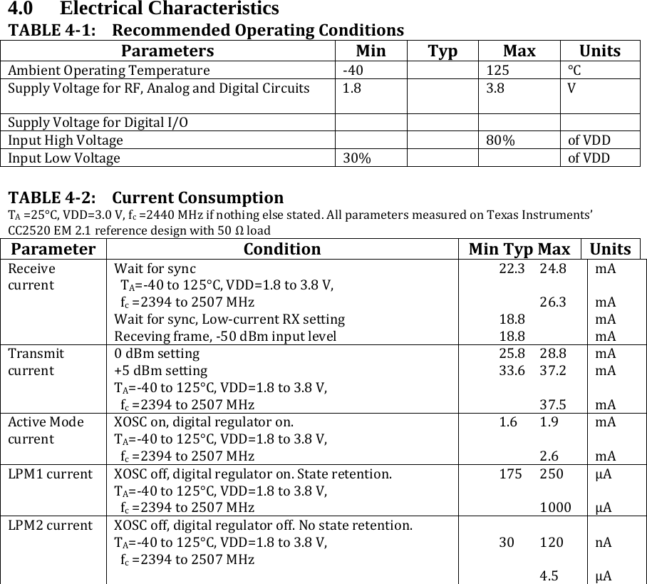
![TABLE43:ReceiverACCharacteristicsTA=25°C,VDD=3.0V,fc=2440MHzifnothingelsestated.AllparametersmeasuredonTexasInstruments’CC2520EM2.1referencedesignwith50Ωload.ParameterConditionMinTypMaxUnitsReceiversensitivity[2]requires‐85dBmTA=‐40to125°C,VDD=1.8to3.8V,fc=2394to2507MHz‐99 ‐98 ‐95 ‐88 dBmSaturation [2]requires‐20dBm6dBm InterfererRejectionWantedsignal3dBabovethesensitivitylevel,802.15.4modulatedinterfererat802.15.4channels: ±5MHzfromwantedsignal.[2]requires0dB ±10MHzfromwantedsignal.[2]requires30dB ±20MHzorabove.Wantedsignalat‐82dBm. 49 54 55dBdBdBMaximumSpuriousEmissionConductedmeasurementina50Ωsingleendedload.ComplieswithEN300328,EN300440class2,FCCCFR47,Part15andARIBSTD‐T‐6630–1000MHz1–12.75GHz<‐80 ‐56dBmdBmFrequencyerrortoleranceInputlevelis3dBabovesensitivitylevel. +/‐400 kHzIIP3 ‐24 dBmTABLE44:TransmitterACCharacteristicsParameterConditionMinTypMaxUnitsOutputpowerNote:toreducetheoutputpowervariationovertemperature,itissuggestedthatdifferent0dBmsetting+5dBmsettingTA=‐40to85°C,VDD=2.0to3.8V,fc=2394to2507MHzTA=‐40to85°C,VDD=1.8to3.8V,‐3 1 52 5 7‐3 8dBmdBmdBm](https://usermanual.wiki/eco-power-design/ECOEWI.Manual-r1/User-Guide-2273568-Page-15.png)
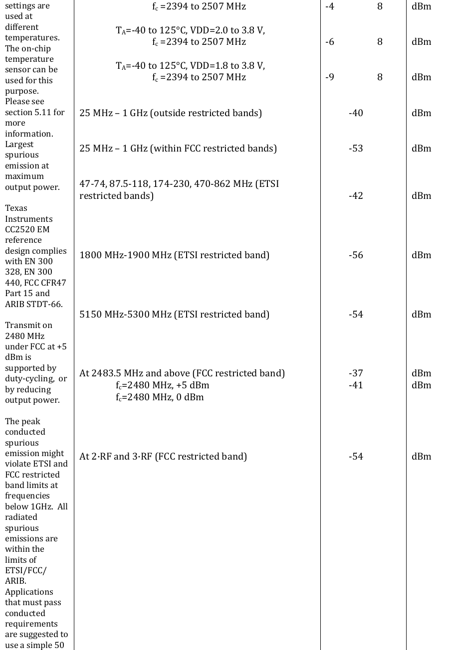
![ΩhighpassfilterbetweenmatchingnetworkandRFconnector.ErrorVectorMagnitude(EVM)[2]requiresmax.35%.Measuredasdefinedby[2]. +5dBmsetting.fc=IEEE802.15.4channels 0dBmsetting.fc=IEEE802.15.4channels62%%](https://usermanual.wiki/eco-power-design/ECOEWI.Manual-r1/User-Guide-2273568-Page-17.png)