ecobee orporated 116151212151 Smart Thermostat User Manual
ecobee Incorporated Smart Thermostat
UserManual.wiki
>
ecobee orporated
>
116151212151 User Manual
User Manual
Navigation menu
Upload a User Manual
Namespaces
Wiki Guide
HTML
PDF
Info
Views
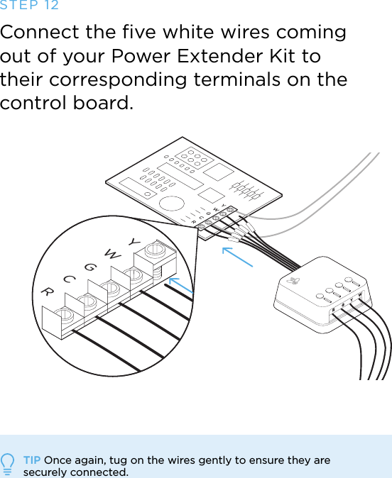
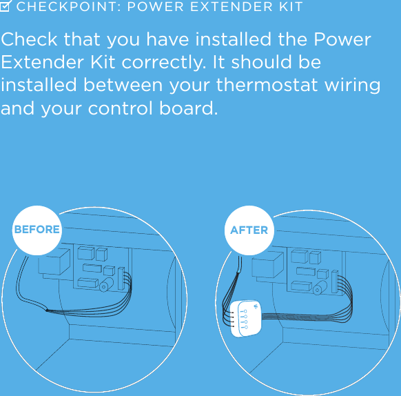
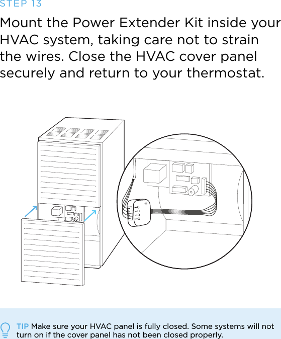
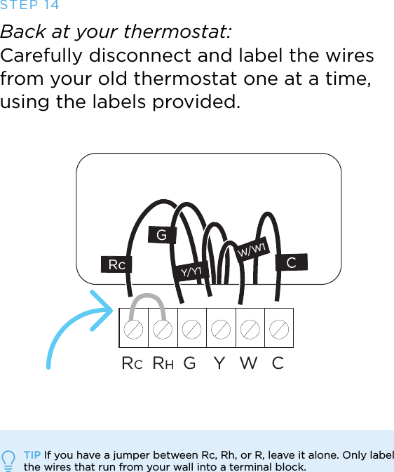
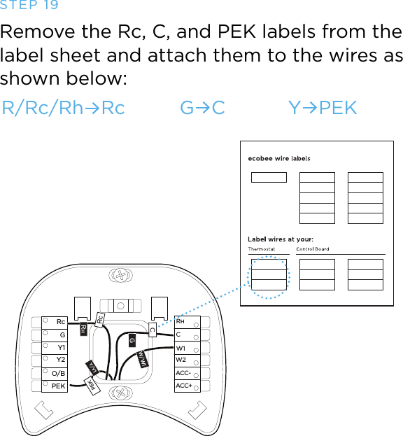
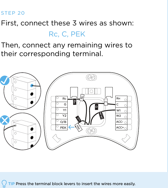
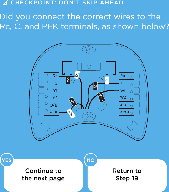
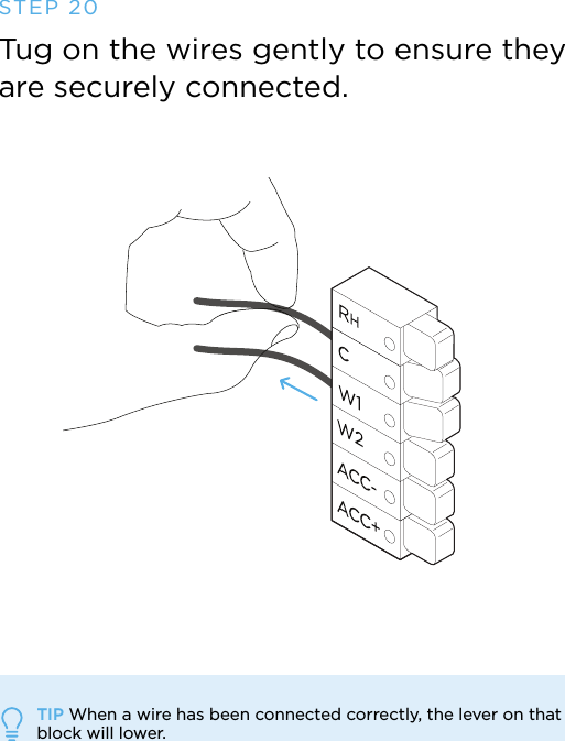
User Manual
Discussion / Help
Navigation