ecobee orporated 116151212151 Smart Thermostat User Manual
ecobee Incorporated Smart Thermostat
User Manual

How to install
your ecobee4

Be happy
You have joined a growing community
of people who want to conserve energy,
save money, and do something good
for our planet.
Let’s get started!

Download the ecobee app
for customized installation
instructions.
Or continue reading!
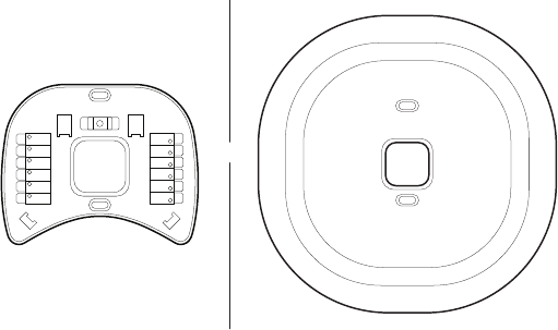
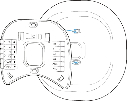
Thermostat Control Board
Rc
G
Y1
Y2
O/B
PEK
ACC-
ACC+
W2
W1
RH
C
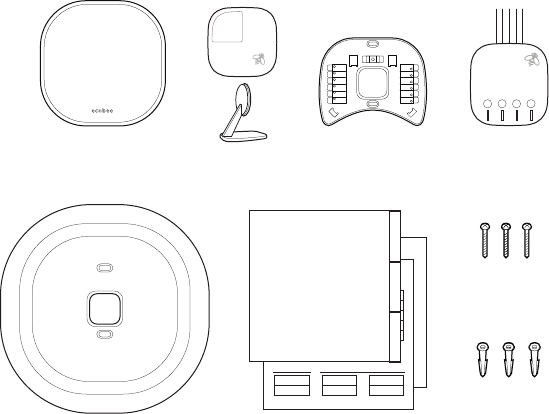
First things first.
Here’s what you’ll find in the box.
ecobee smart
thermostat
BackplateRoom sensor
and stand
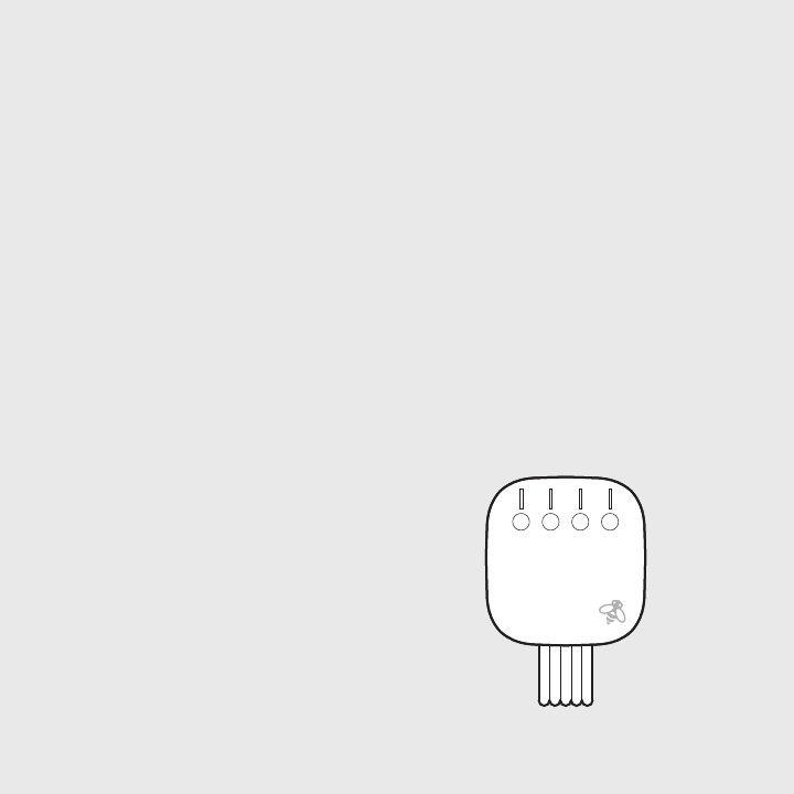
Power Extender
Kit (PEK)
Drywall plugs
Screws
Install guide (this booklet),
room sensor manual, wire labels,
and voice card.
Trim plate
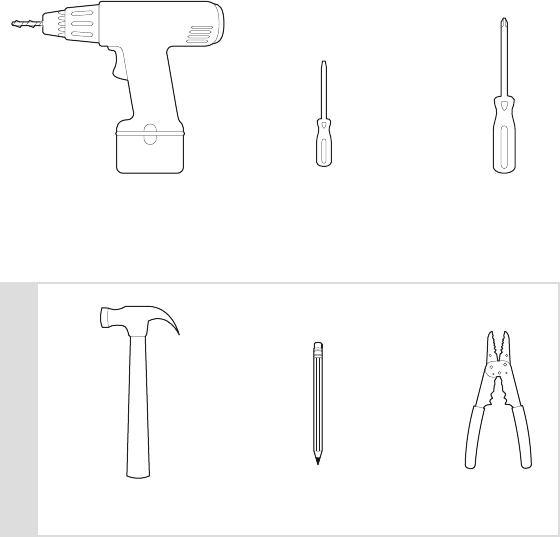
You’ll also need these tools:
Drill for mounting
anchors (3/16” drill bit)
Small
flathead screwdriver
Phillips
screwdriver
Hammer Pencil Wire stripper
OPTIONAL


Guide 1 or Guide 2?
Start here to find out.
The steps in this section will help you
decide which install guide you’ll use
to complete the installation.
These icons indicate useful tips and important reminders.
Start Your Install
ON OFF
ON
OFF
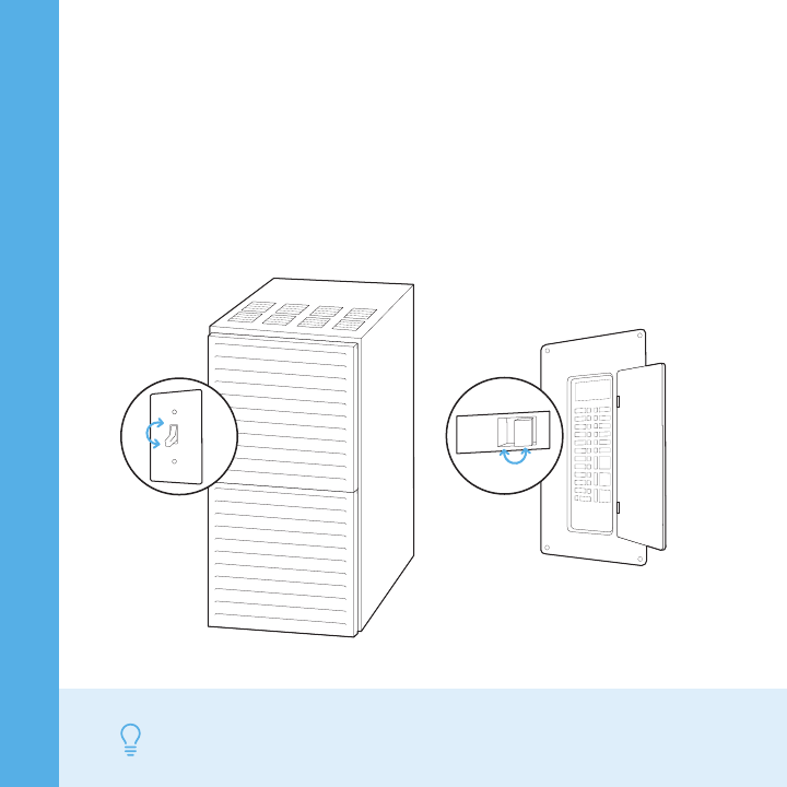
STEP 1
Power off your Heating, Ventilation, and
Air Conditioning (HVAC) system by using
the master switch or circuit breaker box.
This is important for your safety.
TIP Look for your master switch or circuit breaker box in the basement,
attic, utility closet, or behind a wall panel near the thermostat.
TIP If you have a boiler, check to see that the main flame is extinguished.
Confirm your system is off by turning on
your heat (during winter) or your AC
(during summer).
Wait a few minutes—you should not feel
air coming from your vents.
STEP 2
STEP 3
Remove your old thermostat cover from
the wall.
TIP Many thermostats simply pop off or unclip from the base, while others
may have screws that you will need to remove.
L1 L2
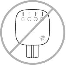
WARNING
HIGH VOLTAGE
110 VAC
OR
120 VAC
OR
240 VAC
YES NO
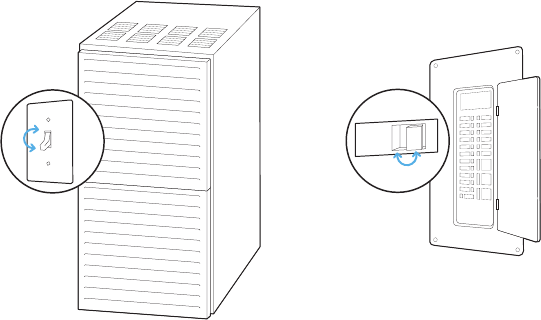
Does your old thermostat’s backplate
have any of these indicators?
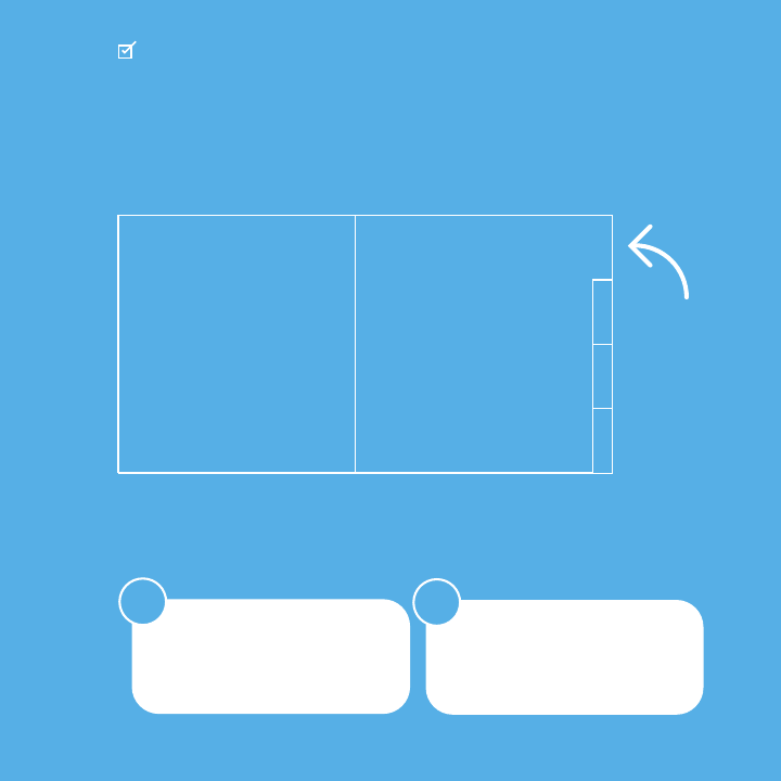
CHECKPOINT: COMPATIBILITY
Sadly, you might
not be compatible. Great, please
continue to
the next page.
You can double-check here:
ecobee.com/compatibility
STEP 4
Take a picture of the wires connected to
the terminals of your old thermostat.
You may need to reference this photo
later on.
WARNING ecobee4 is designed for 24VAC with a 2A maximum
current. Do not connect it to line (high) voltage or millivolt systems.
YES NO
RCRHRCRH
YES NO
CHECKPOINT: C WIRE
Do you have a C wire connected to your
old thermostat?
Continue to
Guide 1
Continue to
Guide 2

GUIDE 1
Install your ecobee
with a C wire
If you have a C wire, it will
power your ecobee.
You won’t need the Power
Extender Kit included
in the box.
Guide 1
YES NO
CHECKPOINT: DON’T SKIP AHEAD
Have you completed steps 1–4 in the
‘Start Your Install’ section?
Continue to
the next page
Return to step 1
in ‘Start Your Install’
W/W1
Y/Y1
Rc
RCRH
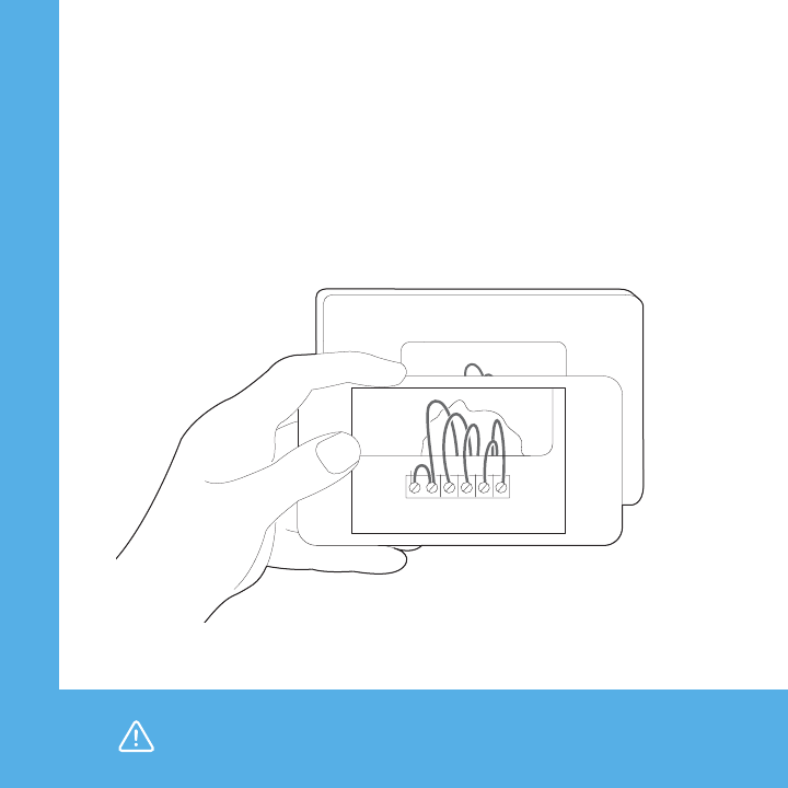
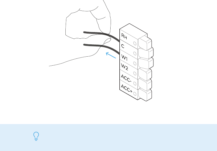
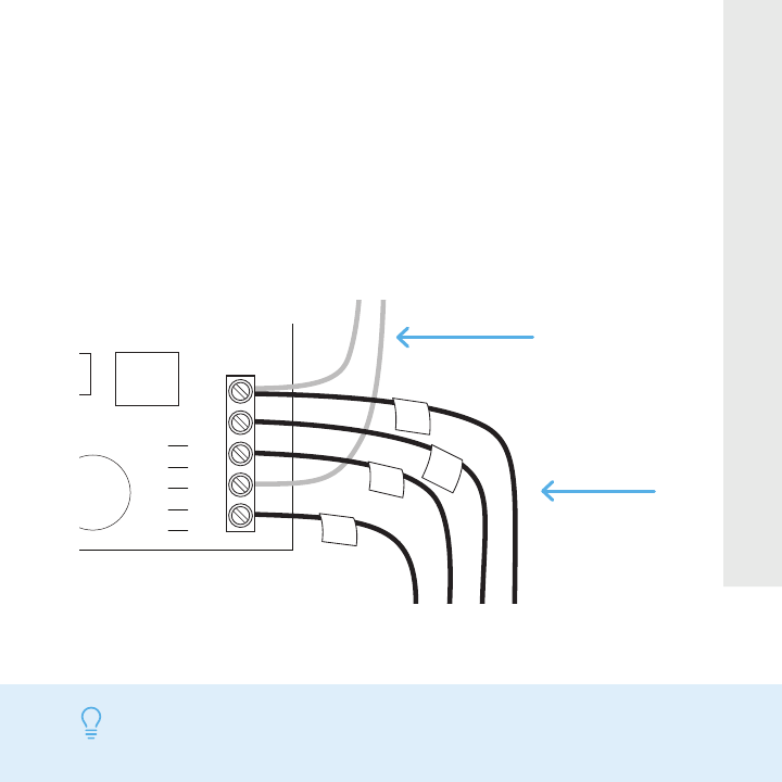
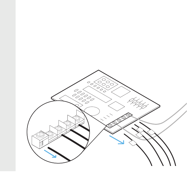
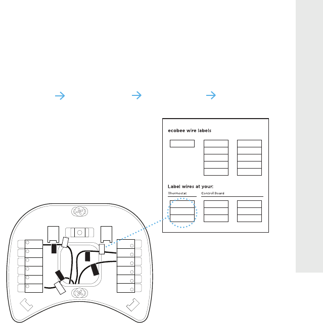
Carefully disconnect and label the wires
from your old thermostat one at a time,
using the labels provided.
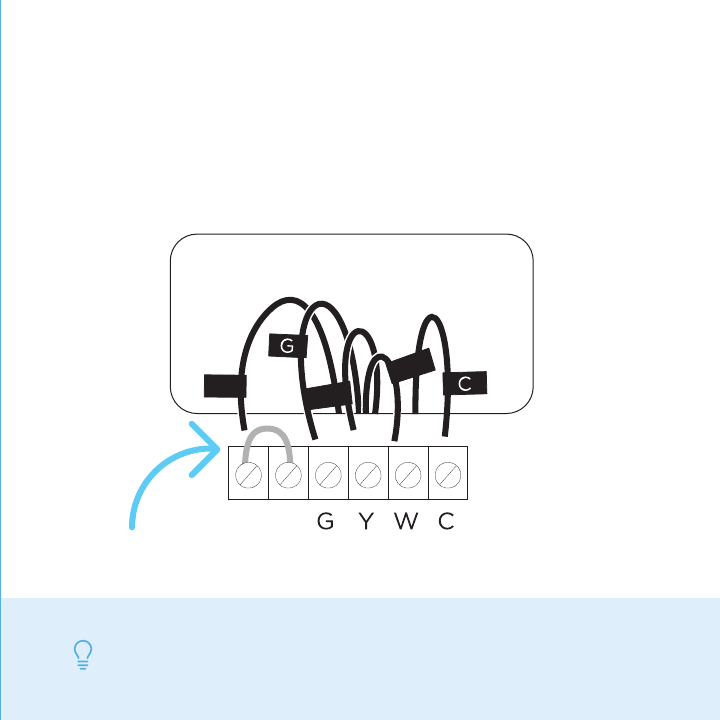
STEP 5
TIP 1 If you have a jumper between Rc, Rh, or R, leave it alone. Only
label the wires that run from your wall into a terminal block.
TIP 2 To install accessories (humidifier, dehumidifier or ventilator)
please refer to the wiring diagrams in the ‘Extras’ section.
R
C
RCRH
W/W1
Y/Y1
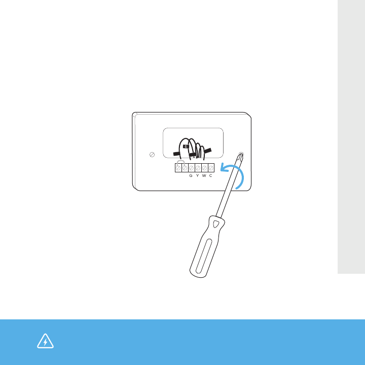
Unscrew the mounting plate of your old
thermostat to remove it from the wall.
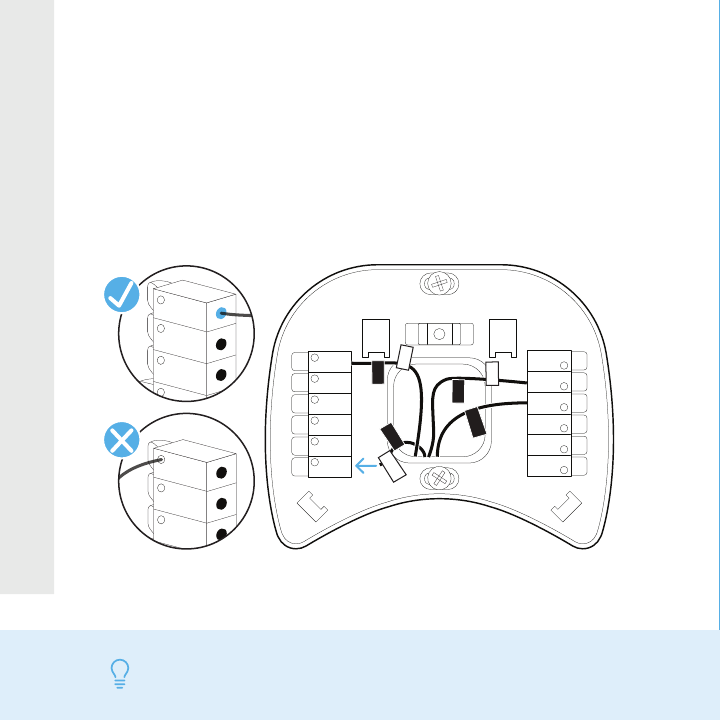
STEP 6
WARNING Be careful, as some thermostats may contain mercury.
Recycle your old thermostat safely with your local hazardous
waste facility.
or
Rc
G
Y1
Y2
O/B
PEK
ACC-
ACC+
W2
W1
RH
C
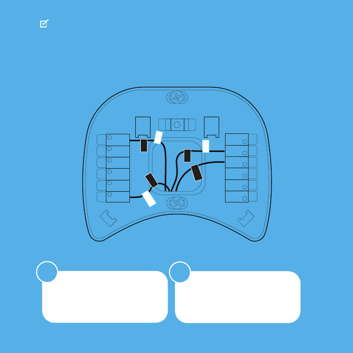
STEP 7
Decide if you want to use the trim plate
with your ecobee. The trim plate is useful
if you want to hide marks or holes left on
the wall by your old thermostat.
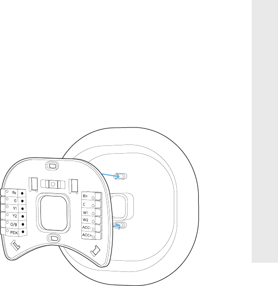
STEP 8: OPTIONAL
If using the trim plate, align the mounting
holes on the trim plate and backplate and
press them into place together.
Rc
G
Y/Y1
W/W1
C
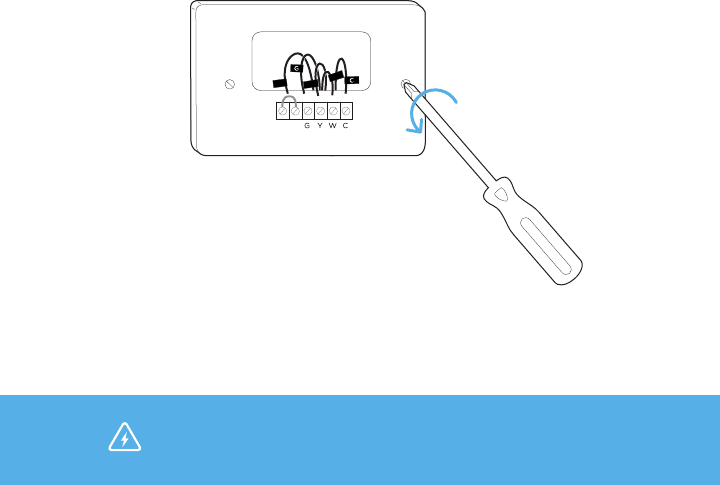
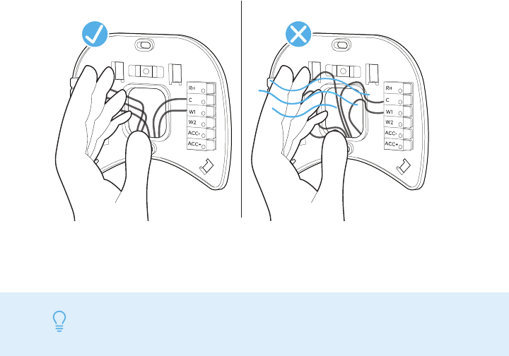
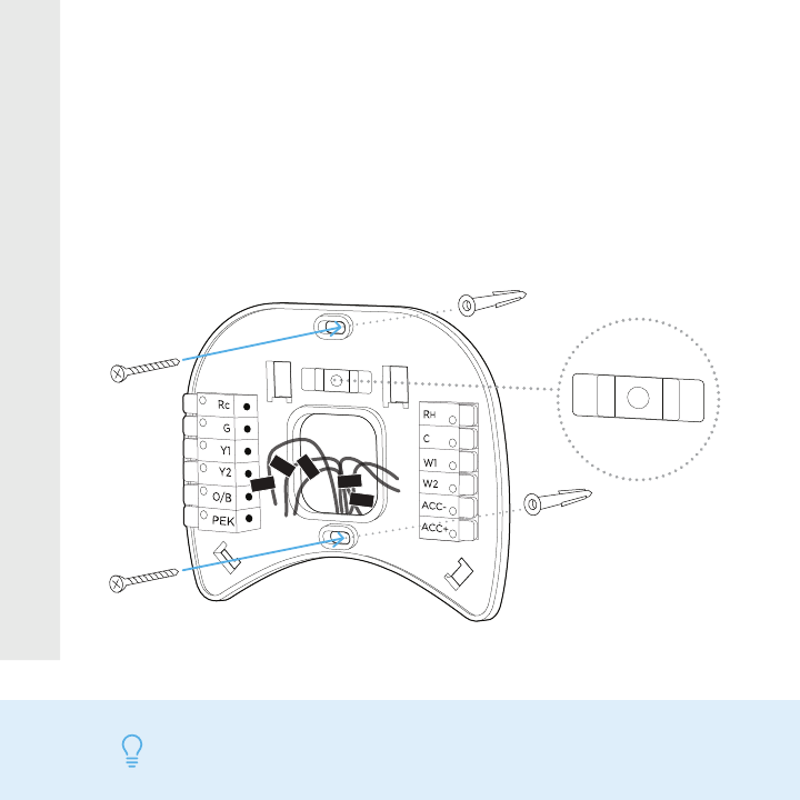
STEP 9
Pull the wires through the hole in the
middle of the backplate and then attach
the backplate to the wall using the
drywall anchors and screws provided.
TIP Use a 3/16” drill bit to drill a hole for the drywall plugs.
YES NO
ACC-
ACC+
W2
W1
RH
C
Rc
G
Y1
Y2
O/B
PEK
ACC-
ACC+
W2
W1
RH
C
Rc
G
Y1
Y2
O/B
PEK
R
G
C
W/W1
Y/Y1
R
H
R
G
C
W/W1
Y/Y1
NO
YES
or
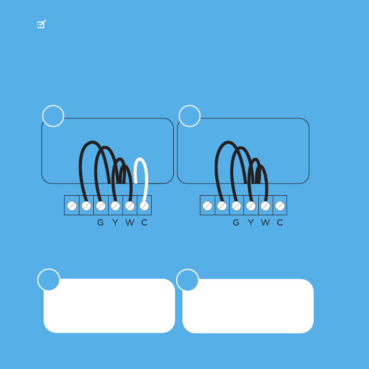
Do you have more than one R wire?
(That includes R, Rc, and Rh)
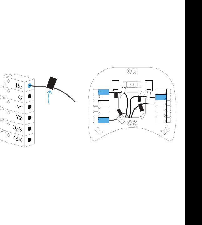
Insert your wires: Insert your single
R, Rc, or Rh wire into
the Rc terminal.
R or Rc Rc
Rh Rh
CHECKPOINT: INSERT YOUR R WIRE(S)
Rc
G
Y1
Y2
O/B
PEK
ACC-
ACC+
W2
W1
RH
C
Rc
G
CW/W1
Y/Y1
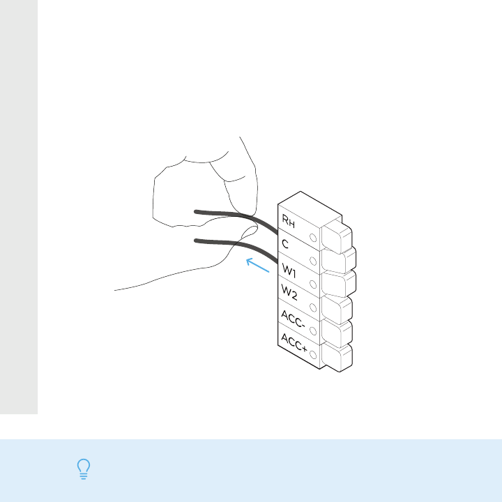
STEP 10
Insert your remaining wires into the side
(not the front) of their corresponding
terminal blocks.
TIP Press the terminal block levers to insert the wires more easily.
Tug on the wires gently to ensure they
are securely connected.
TIP When a wire has been connected correctly, the lever on that block
will lower.
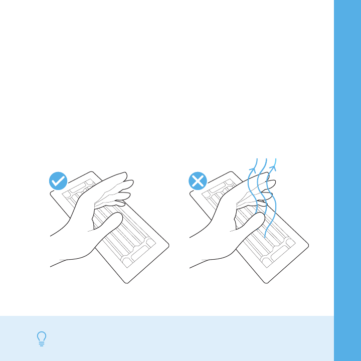
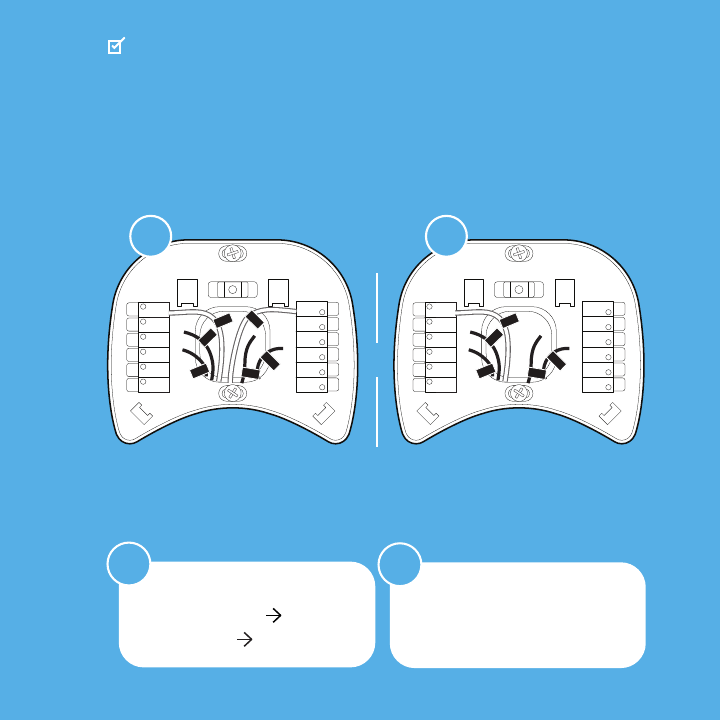
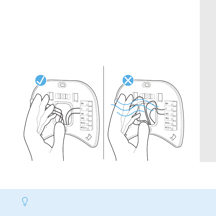
STEP 11
STEP 12
Carefully push any excess wires back into
the hole and ensure there are no drafts
coming from the hole(s) in the wall.
TIP Large holes behind your thermostat will affect temperature
readings. Prevent drafts by covering the hole(s).
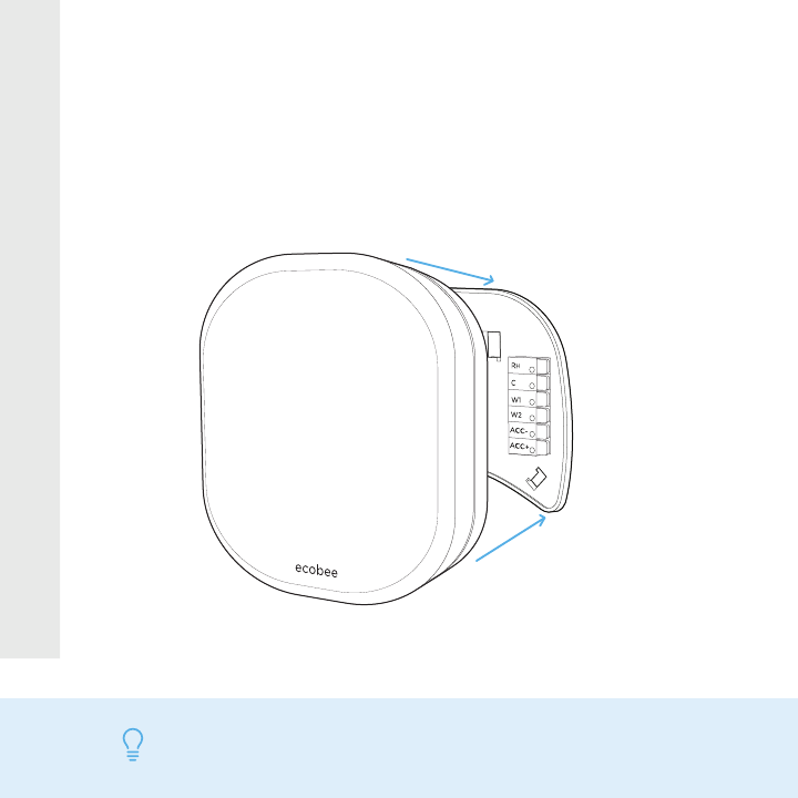
STEP 13
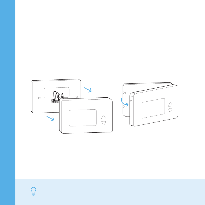
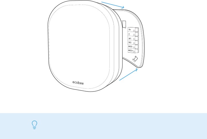
Gently press your ecobee into the
backplate until it ‘clicks’ into place.
TIP If the thermostat ‘rocks’ or is not flush with the wall, be sure the
excess wires are pushed all the way into the wall.
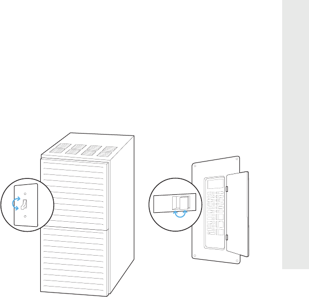
ON OFF
ON
OFF
Turn the power to your HVAC system
back on using the master switch or at
the circuit breaker box.
STEP 14
hi
STEP 15
Say hi to your new ecobee! The screen
will power on and guide you through
the setup and registration.
TIP If your thermostat does not power on, please see the
troubleshooting tips in the ‘Extras’ section.

Congratulations,
you did it!
To complete your setup,
follow the instructions
on your ecobee screen.
ALL DONE!

Install your ecobee
without a C wire
If you don’t have a C wire,
you’ll need to use the
Power Extender Kit (PEK)
included to reliably power
your ecobee.
GUIDE 2
Guide 2
YES NO
CHECKPOINT: DON’T SKIP AHEAD
Have you completed steps 1–4 in the
‘Start Your Install’ section?
Continue to
the next page
Return to step 1
in ‘Start Your Install’
RCRHRCRH
NO
YES
YES NO
Continue to
the next page
The Power Extender Kit
will work with your system!
The Power Extender Kit requires your
system to have the following wires:
4 wires: W/W1, Y/Y1, G, and R (or Rc or Rh)
or 3 wires: Y/Y1, G, and R (or Rc or Rh)
CHECKPOINT: 3 OR 4 WIRES
Do you have these wires?
Contact us
To proceed call 1.877.932.6233
or email support@ecobee.com
ecobee wire labels
Label wires at your:
Thermostat Control Board
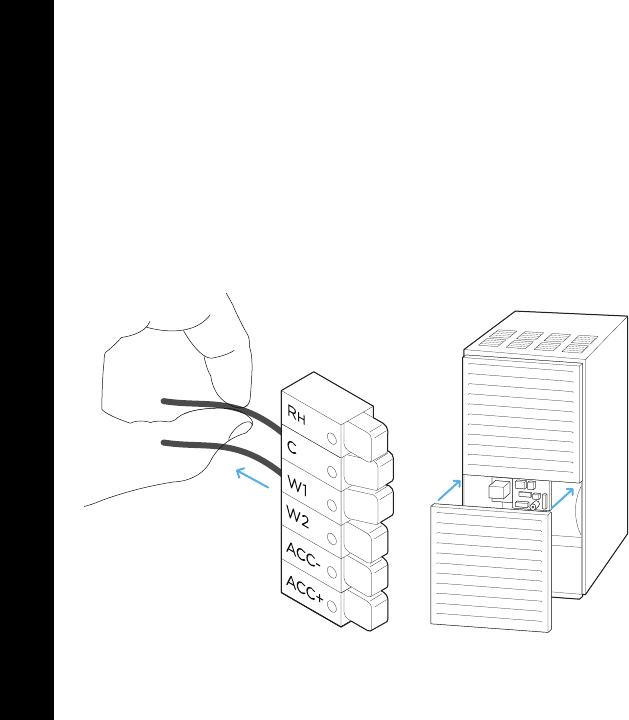
STEP 5
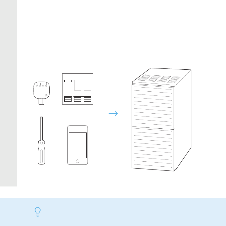
Take your Power Extender Kit, wire labels,
tools, your smartphone, and go to your
HVAC system.
TIP Your HVAC system can most often be found in your basement or
your attic.
Control board
Y
W
G
C
R
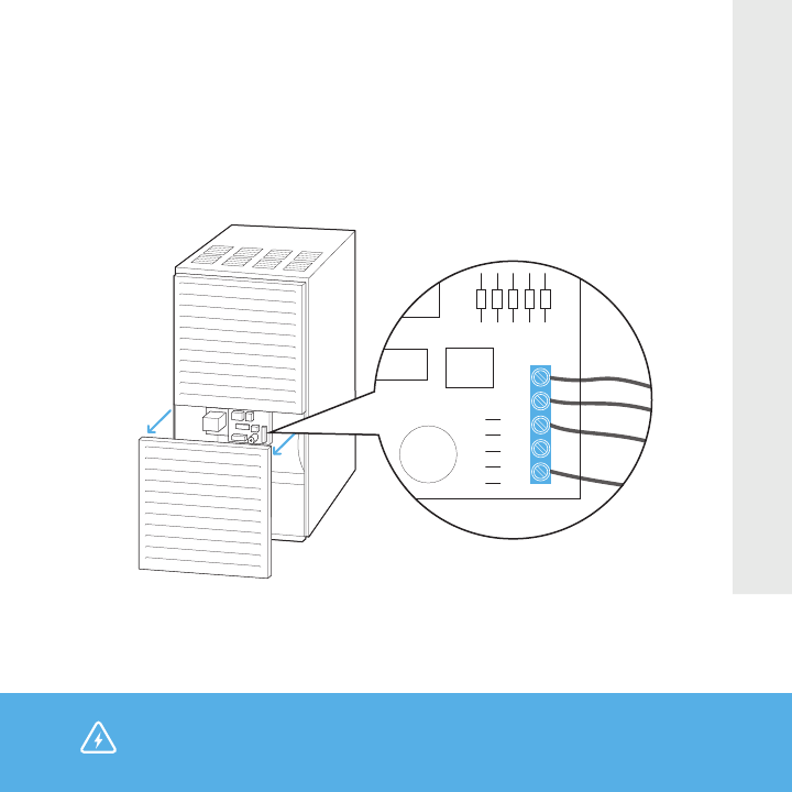
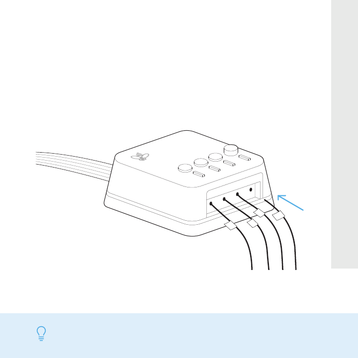
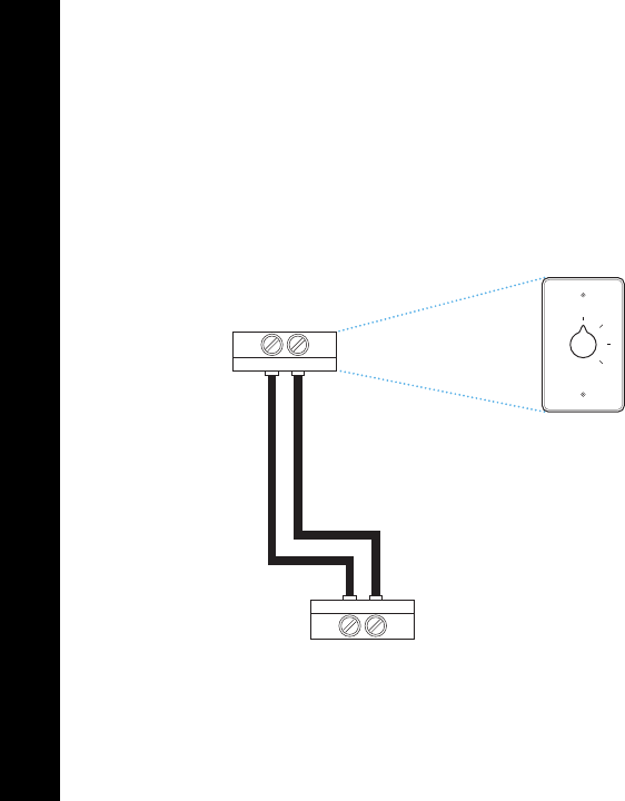
STEP 6
Open your HVAC system’s cover to reveal
the control board.
WARNING HVAC systems contain high voltage wires. Use caution
when working with the control board.
Y
W
G
C
R
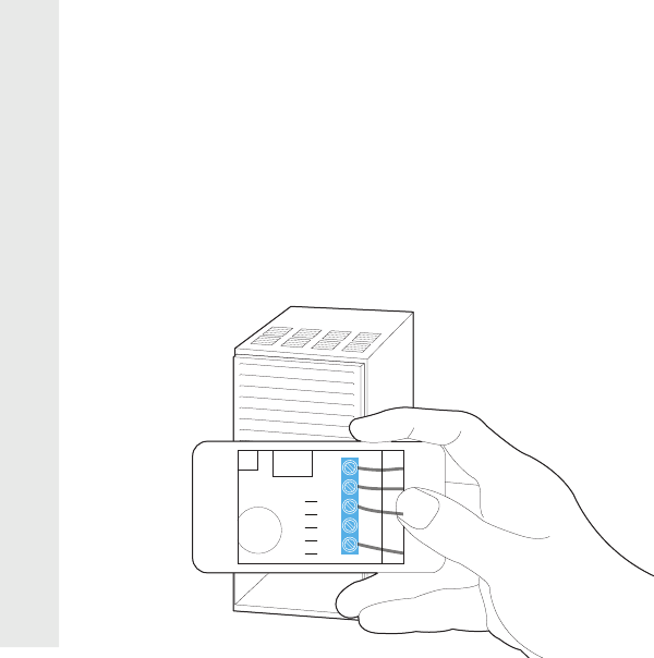
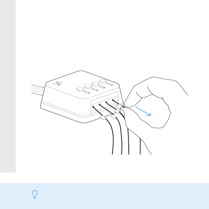
STEP 7
Take a picture of the wires connected
to your control board. You may need to
reference this photo later on.
Y
W
G
C
R
W
Y
G
R
STEP 8
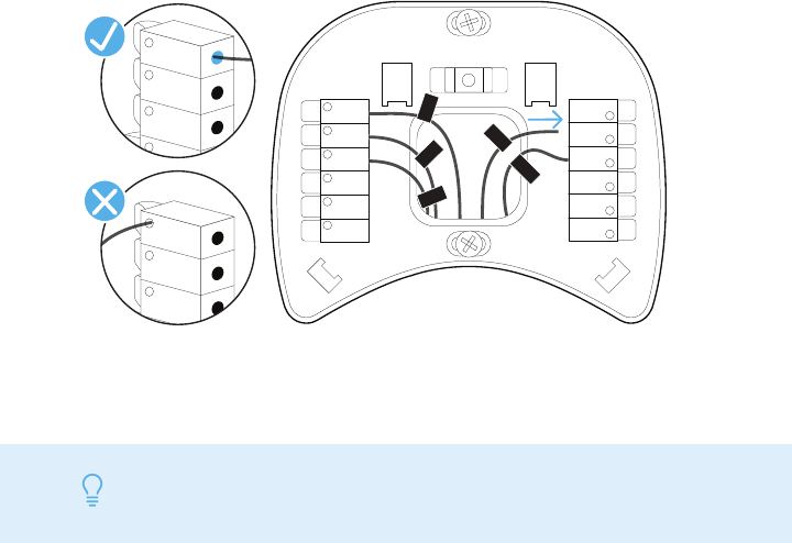
Label only the R, Y or Y1, G, and W or W1
wires with the matching labels provided.
If you have more than one wire going into
these terminals, only label those going to
your thermostat.
TIP If you have wires connected to both Rc and Rh terminals at the control-
board you may have a two transformer system. Please contact support to
help you with installation: 1.877.932.6233 or support@ecobee.com.
Wires going
to your A/C
(ignore these)
Wires going
to your
thermostat
W
Y
R
Y
W
G
C
R
G
Y
W
G
C
R
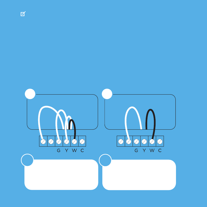
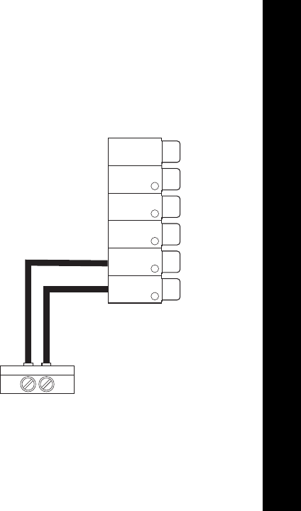
STEP 9
Disconnect the wires labeled R, Y, G, and
W from the control board.
RGYW
W
G
Y
R
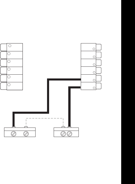
STEP 10
Connect the wires you disconnected from
the control board into their matching gray
terminal blocks on the Power Extender Kit.
TIP Press the buttons to insert the wires more easily.
RGYW
G
Y
R
W
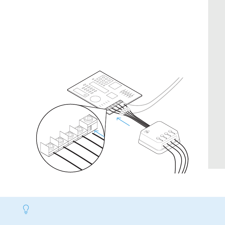
STEP 11
Tug on the wires gently to ensure they
are securely connected.
TIP When a wire has been connected correctly, the button on that
block will lower.
Y
W
G
C
R
R G Y W
Y
W
G
C
R
STEP 12
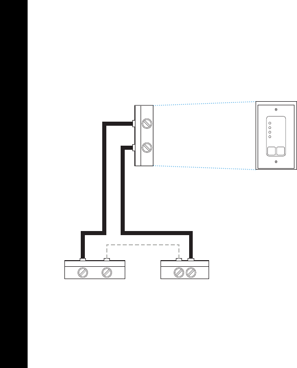
Connect the five white wires coming
out of your Power Extender Kit to
their corresponding terminals on the
control board.
TIP Once again, tug on the wires gently to ensure they are
securely connected.
BEFORE
AFTER
BEFORE
AFTER
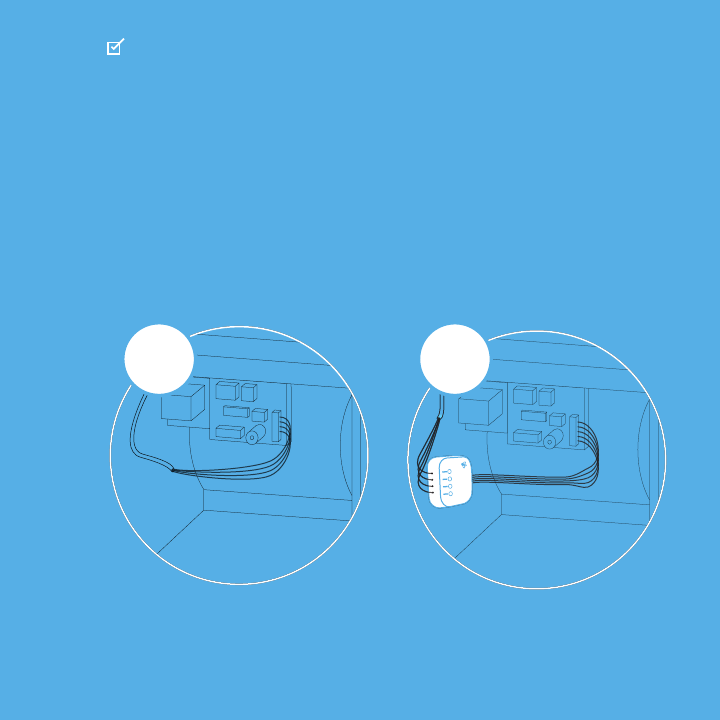
CHECKPOINT: POWER EXTENDER KIT
Check that you have installed the Power
Extender Kit correctly. It should be
installed between your thermostat wiring
and your control board.
TIP Make sure your HVAC panel is fully closed. Some systems will not
turn on if the cover panel has not been closed properly.
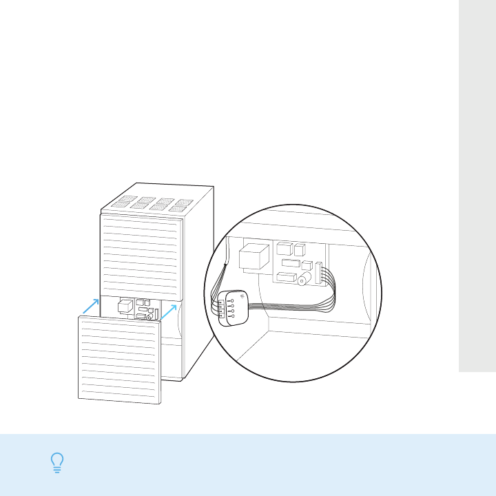
STEP 13
Mount the Power Extender Kit inside your
HVAC system, taking care not to strain
the wires. Close the HVAC cover panel
securely and return to your thermostat.
W/W1
Y/Y1
Rc
RCRH
STEP 14
Back at your thermostat:
Carefully disconnect and label the wires
from your old thermostat one at a time,
using the labels provided.
TIP If you have a jumper between Rc, Rh, or R, leave it alone. Only label
the wires that run from your wall into a terminal block.
R
C
W/W1
Y/Y1
RCRH
Unscrew the mounting plate of your old
thermostat to remove it from the wall.
STEP 15
WARNING Be careful, as some thermostats may contain mercury. Recycle
your old thermostat safely with your local hazardous waste facility.
or
Rc
G
Y1
Y2
O/B
PEK
ACC-
ACC+
W2
W1
RH
C
STEP 16
Decide if you want to use the trim plate
with your ecobee. The trim plate is useful
if you want to hide marks or holes on the
wall left by your old thermostat.
If using the trim plate, align the mounting
holes on the trim plate and backplate and
press them into place together.
STEP 17: OPTIONAL
Rc
G
Y/Y1
W/W1
C
STEP 18
Pull the wires through the hole in the
middle of the backplate and then attach
it to the wall using the drywall anchors
and screws provided.
TIP Use a 3/16” drill bit to drill a hole for the drywall plugs.
Rc
G
Y1
Y2
O/B
PEK
ACC-
ACC+
W2
W1
RH
C
Rc
R
H
G
C
W/W1
PEK
Y/Y1
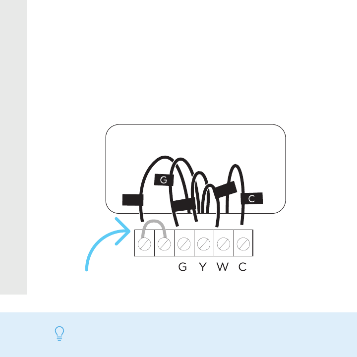
STEP 19
Remove the Rc, C, and PEK labels from the
label sheet and attach them to the wires as
shown below:
R/Rc/Rh Rc G C Y PEK
TIP Press the terminal block levers to insert the wires more easily.
Rc
G
Y1
Y2
O/B
PEK
ACC-
ACC+
W2
W1
RH
C
Rc
R
H
G
C
W/W1
PEK
Y/Y1
STEP 20
First, connect these 3 wires as shown:
Rc, C, PEK
Then, connect any remaining wires to
their corresponding terminal.
ACC-
ACC+
W2
W1
RH
C
Rc
G
Y1
Y2
O/B
PEK
Rc
RH
G
C
W/W1
PEK
Y/Y1
YES NO
Continue to
the next page
Did you connect the correct wires to the
Rc, C, and PEK terminals, as shown below?
CHECKPOINT: DON’T SKIP AHEAD
Return to
Step 19
TIP When a wire has been connected correctly, the lever on that
block will lower.
STEP 20
Tug on the wires gently to ensure they
are securely connected.
Carefully push any excess wires back into
the hole and ensure there are no drafts
coming from the hole(s) in the wall.
STEP 21
TIP Large holes behind your thermostat will affect temperature readings.
Prevent drafts by covering the hole(s).
STEP 22
Gently press your ecobee into the
backplate until it ‘clicks’ into place.
TIP If the thermostat ‘rocks’ or is not flush with the wall, be sure the excess
wires are pushed all the way into the wall.
ON OFF
ON
OFF
Turn the power to your HVAC system
back on using the master switch or at
the circuit breaker box.
STEP 23
hi
STEP 24
Say hi to your new ecobee! The screen
will power on and guide you through the
setup and registration.
TIP If your thermostat does not power on, please see the troubleshooting
tips in the ‘Extras’ section.
ALL DONE!
Congratulations,
you did it!
To complete your setup,
follow the instructions on
your ecobee screen.


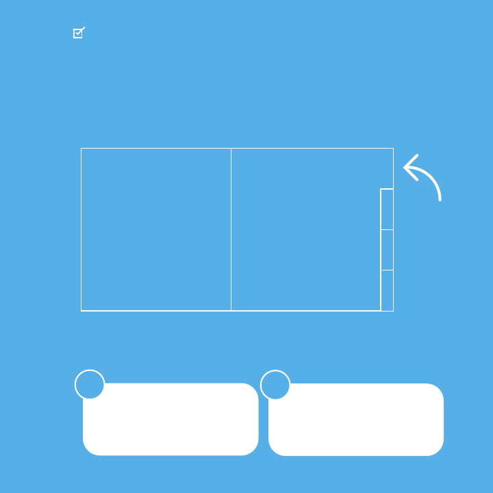
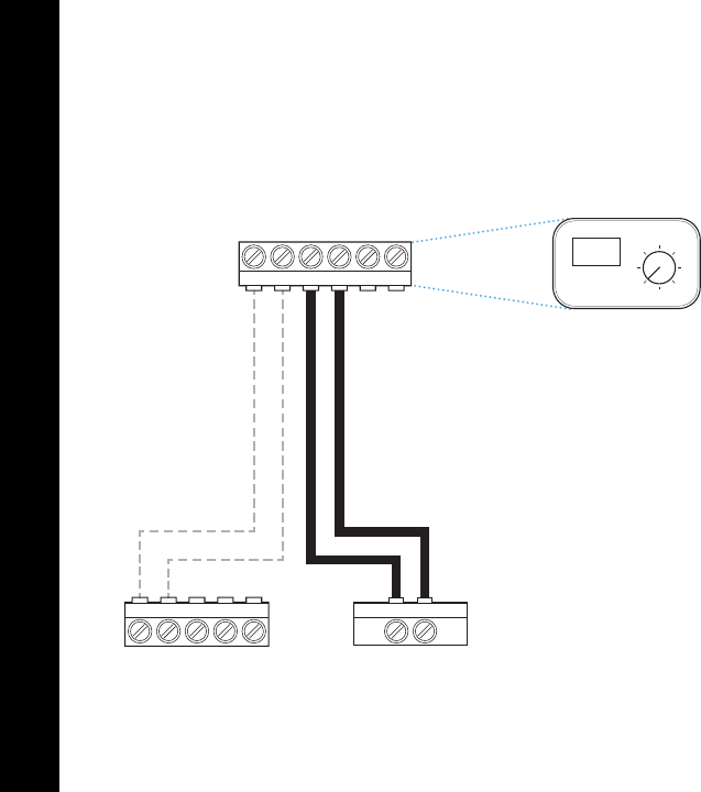
In here you’ll find:
EXTRAS
— Troubleshooting
— Meet your ecobee
— Wiring diagrams
— Warranty and Legal
Extras
1. Check that all wires are properly
inserted into the terminal blocks
at the thermostat. Tug on the
wires to ensure they are not loose.
If your ecobee doesn’t turn on, please try
these steps:
TROUBLESHOOTING
2. Make sure your HVAC cover pan-
el is closed. Some systems will
not turn on if the cover panel
has not been closed properly.
R
Rc
PEK
ACC-
ACC+
W2
W1
R
H
Rc
R
H
G
C
W/W1
PEK
Y/Y1
G
Y1
Y2
O/B
C
3. If you have only one R wire (ei-
ther R, Rc, or Rh), make sure it’s
inserted into the Rc terminal.
4. If you installed the Power Extender
Kit, make sure you inserted the
wires into the correct terminals:
ecobee support is here to help:
CALL
1 877.932.6233 (North America)
1 647.428.2220 (International)
Your R, Rc,
or Rh wire
TROUBLESHOOTING
EMAIL
support@ecobee.com
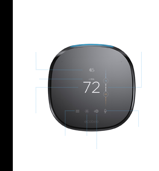
Slider to adjust
Temperature
Humidity
System Mode
Indoor
Temperature
Weather
Quick
Changes
Voice
Control
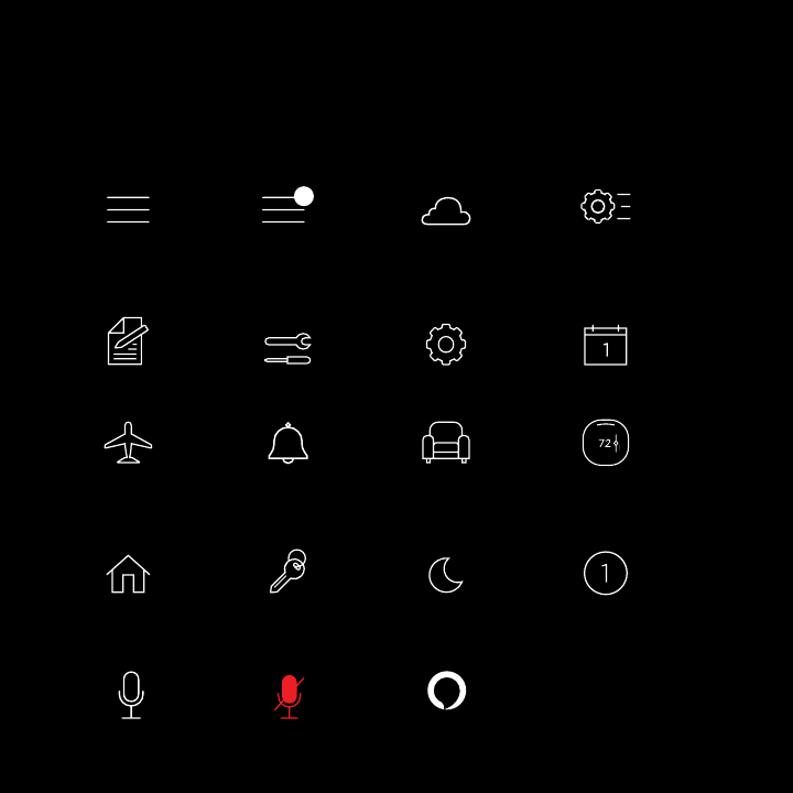
MEET YOUR ECOBEE
Here’s what you’ll see on the home screen:
Menu

MEET YOUR ECOBEE
System Mode
Shows your current ecobee setting
(heat/cool/auto/off).
Humidity
Shows the indoor humidity in
your home.
Indoor Temperature
Shows the indoor temperature in
your home.
Slider to adjust Temperature
Slide the bubble up or down to
adjust your preferred temperature.
And here’s what that means:
Menu
Allows you to control your system,
schedule a vacation, and more.
Weather
Shows the local weather and forecast
for the week.
Quick Changes
Touch this button to easily switch
between Home and Away.
Voice Control
Allows you to turn volume up/down
and enable/disable microphone.
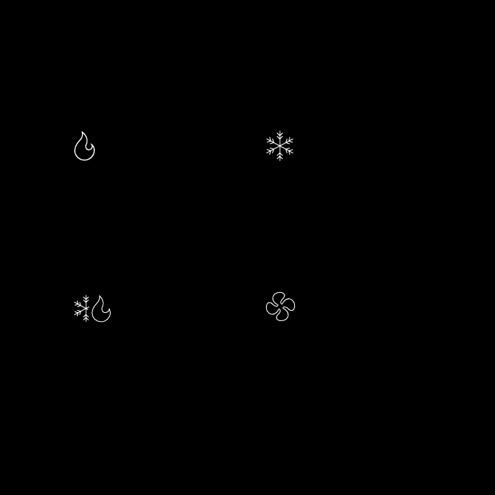
Heat
Your system is in heat mode.
A white icon means your system
is off. An orange icon means your
system is running.
Cool
Your system is in cool mode. A white
icon means your system is off. A blue
icon means your system is running.
Fan
Your fan is currently running.
Auto
Your system is in Auto mode,
meaning your system will heat or
cool as required.
MEET YOUR ECOBEE
These system mode icons are shown on
the Home screen and in Quick Changes.
2
Home
MENU
Away
Menu
(with notification)
Quick
Changes
Weather
Registration
Vacation
System Settings Schedule
Custom 1 (of 5)
AboutAlerts and
Reminders
Sleep
Comfort Settings
COMFORT SETTINGS
VOICE
More common icons you’ll find:
Menu
HOME SCREEN
Voice Control Microphone Off Push to Talk
Rc
G
Y1
Y2
O/B
PEK
ACC-
ACC+
W2
W1
C
RH
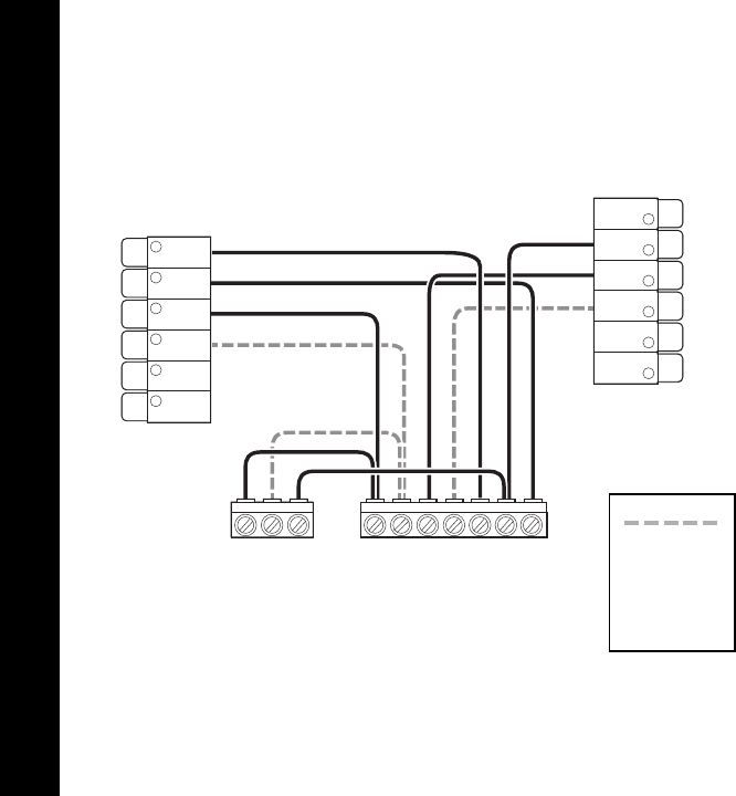
Y1 Y2 C Y1 Y2 W1 W2 R C G
WIRING DIAGRAM
Conventional heating and cooling
(up to 2 stages each).
Air Conditioner Furnace
Stage 2
heat
and cool,
if applicable
NOTE Do not connect any jumper wires between Rc and Rh. ecobee does this
automatically. The R wire needs to go into the Rc terminal on
your ecobee.
Rc
G
Y1
Y2
O/B
PEK
ACC-
ACC+
W2
W1
C
RH
W2O/B Y1 Y2 R C W1O/B W2 Y1 GY2 R C
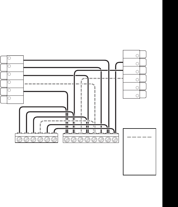
NOTE Do not connect any jumper wires between Rc and Rh. ecobee does
this automatically. The R wire needs to go into the Rc terminal on
your ecobee.
Heat pump (air or geothermal) with
auxiliary heat.
Heat Pump Air Handler
Stage 2
compressor
and auxiliary
heat,
if applicable
WIRING DIAGRAM
Rc
G
Y1
Y2
O/B
PEK
ACC-
ACC+
W2
W1
C
RH
Y1 Y2 R C G
Y2Y1 C O/B* W1 W2R
Air
Handler
Air Conditioner
or Heat Pump*
Boiler
WIRING DIAGRAM
Boiler or radiant system with air handler
and conventional cooling or heating.
*Stage 2 heat
and cool,
if applicable
*Reversing
valve for heat
pumps only
NOTE Do not connect any jumper wires between Rc and Rh. ecobee does this
automatically. The R wire needs to go into the Rc terminal on
your ecobee.
Rc
G
Y1
Y2
O/B
PEK
R G Y W
W Y G R
ACC-
ACC+
W2
W1
C
RH
WIRING DIAGRAM
Power Extender Kit thermostat wiring.
NOTE Do not connect any jumper wires between Rc and Rh. ecobee does
this automatically. The R wire needs to go into the Rc terminal on
your ecobee.
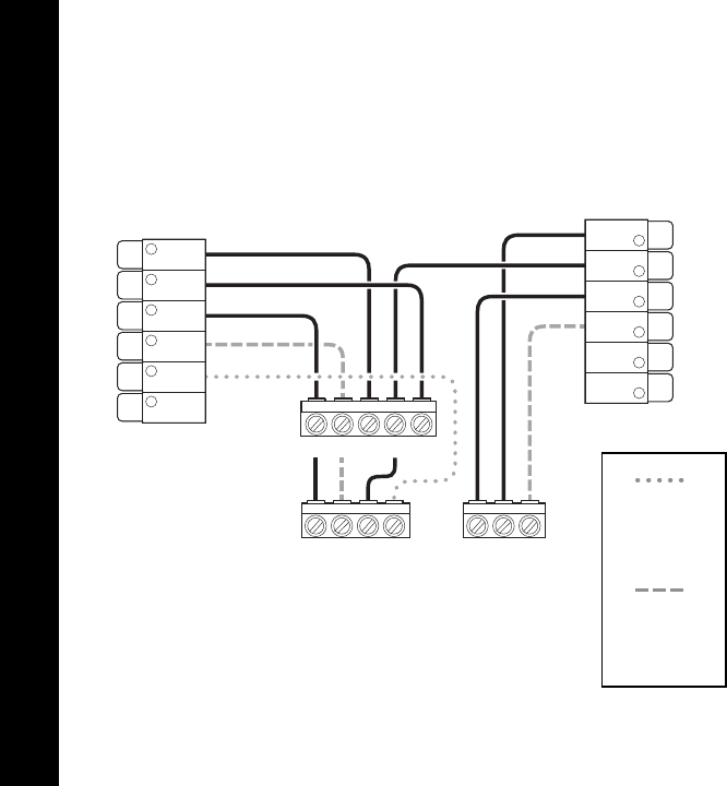
HUMIDIFIER / DEHUMIDIFIER (1-WIRE SETUP)
Step 1: Locate the humidifier/dehumidifer
control and remove the plate.
R C U U
U U
ODT
R C G Y W
Humidifier/
Dehumidifier
Furnace
Control Board
Humidistat
R C G Y W U U
Furnace
Control Board
ACC+
ACC-
W2
W1
C
RH
RC
G
Y1
Y2
O/B
PEK
Humidifier/
Dehumidifier
HUMIDIFIER / DEHUMIDIFIER (1-WIRE SETUP)
Step 2: Wire the humidifier/dehumidifer
as shown below.
NOTE During setup, select 1-wire (ACC+) accesory on the
thermostat screen.
HUMIDIFIER / DEHUMIDIFIER (2-WIRE SETUP)
H/U
H/U
U U
HUM
(24V)
C
Humidifier/
Dehumidifier
Furnace
Accesory Terminals
Humidistat
Step 1: Locate the humidifier/dehumidifer
control and remove the plate.
HUM U U
(24V)
C
Furnace
Accesory
Terminals
Humidifier/
Dehumidifier
ACC+
ACC-
W2
W1
C
RH
RC
G
Y1
Y2
O/B
PEK
NOTE During setup, select 2-wire (ACC+, ACC-) accesory on the
thermostat screen.
HUMIDIFIER / DEHUMIDIFIER (2-WIRE SETUP)
Step 2: Wire the humidifier/dehumidifer
as shown below.
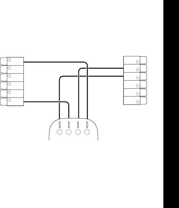
VENTILATOR (2-WIRE SETUP)
Ventilator /ERV/HRV
Ventilator
Timer
Control
Ventilator
Timer
Control
R G
R G (HI/LO)
Step 1: Locate the ventilator timer control
and remove the plate.
VENTILATOR (2-WIRE SETUP)
ACC+
ACC-
W2
W1
C
RH
ERV/HRV
R G (HI/LO)
NOTE During setup, select 2-wire (ACC+, ACC-) accesory on the
thermostat screen.
Step 2: Wire the ventilator as shown below.

LEGAL
Approvals
This product was designed and built in
accordance to RoHS directive 2002/95/EC
and contains no hazardous substances as
defined by this directive.
FCC Compliance Statement
Compliance Notice:
This equipment has been tested and found to
comply with the limits for a Class B digital
device, pursuant to part 15 of the FCC Rules.
These limits are designed to provide
reasonable protection against harmful
interference in a residential installation. This
equipment generates, uses and can radiate
radio frequency energy and, if not installed
and used in accordance with the instructions,
may cause harmful interference to radio
communications. However, there is no
guarantee that interference will not occur in a
particular installation. If this equipment does
cause harmful interference to radio or
television reception, which can be determined
by turning the equipment off and on, the user
is encouraged to try to correct the interference
by one or more of the following measures:
–Reorient or relocate the receiving antenna.
–I ncrease the separation between the
equipment and receiver.
– Connect the equipment into an outlet on a
circuit different from that to which the receiver
is connected.
–Consult the dealer or an experienced radio/TV
technician for help.
This device complies with part 15 of FCC rules.
Operation is subject to the following two
conditions:
1. This device may not cause harmful
interference.
2. This device must accept any interference
received, including interference that may
cause undesired operation.
Change or modifications that are not expressly
approved by the manufacturer could void the
user’s authority to operate the equipment.
RF Exposure Information:
This equipment complies with FCC radiation
exposure limits set forth for an uncontrolled
environment. In order to avoid the possibility
of exceeding the FCC radio frequency
exposure limits, human proximity to the
antenna shall not be less than 8 inches during
normal operation.
Industry Canada (IC)
Compliance Notice:
This device complies with Industry Canada
license-exempt RSS standard(s).
Operation is subject to the following two
conditions:

defective Products, at no charge. Any
replacement and/or repaired device are
warranted for the remainder of the original
warranty or ninety (90) days, whichever is
longer. A proof-of-purchase will be required
from the Customer in order for ecobee to
provide a replacement and/or repaired device.
This Warranty is valid only for Product installed
in the country in which it is purchased.
If the product is defective, call Customer
Service at 1-877-932-6233. ecobee will make
the determination whether a replacement
product can be sent to you or whether the
product should be returned to our address.
In the event of a failure of a Product, Customer
may:
a. if Customer did not purchase the Product
directly from ecobee, contact the third party
contractor from whom the Product was
purchased to obtain an equivalent
replacement product, provided the
contractor determines that the returned
Product is defective and Customer is
otherwise eligible to receive a replacement
product;
b. contact ecobee directly for service
assistance at 1-877-932-6233 and ecobee
will make the determination whether an
advance equivalent replacement Product
can be sent to Customer with return
shipping supplies (in which case a hold shall
be put on Customer’s credit card for the
value of the replacement Product until
ecobee has received the defective Product).
1. This device may not cause interference.
2. This device must accept any interference,
including interference that may cause
undesired operation of the device.
This Class B digital apparatus complies with
Canadian ICES-003.
RF Exposure Statement:
This equipment complies with IC RSS-102
radiation exposure limits set forth for an
uncontrolled environment. This transmitter
must be installed to provide a separation
distance of at least 8 inches from all persons
and must not be collocated or operating in
conjunction with any other antenna or
transmitter.
FCC ID: WR911615121215
IC ID: 7981A – 11615121215
CAN ICES-3 (B)/NMB-3(B)
Assembled in China.
Warning: Changes or modifications not
expressly approved by ecobee Inc. could void
the user’s authority to operate the equipment.
3-Year Limited Warranty
ecobee warrants that for a period of three (3)
years from the date of purchase by the
consumer (“Customer”), the ecobee4 (the
“Product”) shall be free of defects in materials
and workmanship under normal use and
service. During the warranty period, ecobee
shall, at its option, repair or replace any

Product should be returned to our address.
If the returned Product is found by ecobee
to be defective and Customer is otherwise
eligible to receive a replacement product, no
amount shall be charged to Customer’s
credit card; or
c. Ship the defective Product directly to
ecobee, in which case Customer shall
contact ecobee directly at 1-877-932-6233,
so ecobee can make the required shipping
arrangements. Upon receipt of the defective
Product, ecobee will ship an equivalent
replacement product to Customer, provided
the returned Product is found by ecobee to
be defective and Customer is otherwise
eligible to receive a replacement product.
This warranty does not cover removal or
reinstallation costs and shall not apply if the
damages were found to be caused by
something other than defects in materials or
workmanship, including without limitation, if
the Product:
– was operated/stored in abnormal use
or maintenance conditions;
– is repaired, modified or altered, unless ecobee
expressly authorizes such repair, modification
or alteration in writing;
– was subject to abuse, neglect, electrical fault,
improper handling, accident or acts of nature;
– was not installed by a licensed Heating
Ventilating and Air Conditioning (HVAC)
contractor; or
- was installed improperly
ecobee’s sole responsibility shall be to repair or
replace the Product within the terms stated
above. ECOBEE SHALL NOT BE LIABLE
FOR ANY LOSS OR DAMAGE OF ANY KIND,
INCLUDING ANY SPECIAL, INCIDENTAL OR
CONSEQUENTIAL DAMAGES RESULTING,
DIRECTLY OR INDIRECTLY, FROM ANY
BREACH OF ANY WARRANTY, EXPRESS
OR IMPLIED, OR ANY OTHER FAILURE OF
THIS PRODUCT. Some US states and
Canadian provinces do not allow the
exclusion or limitation of incidental or
consequential damages, so the above
limitation or exclusion may not apply to you.
ecobee’s responsibility for malfunctions and
defects in materials and workmanship is
limited to repair and replacement as set
forth in this warranty statement. All express
and implied warranties for the product,
including but not limited to any implied
warranties and conditions of merchantabili-
ty and fitness for a particular purpose, are
limited to the three-year duration of this
limited warranty. No warranties, whether
expressed or implied, will apply after the
limited warranty period has expired. Some
US states and Canadian provinces do not
allow limitations on how long an implied
warranty lasts, so this limitation may not
apply.
ecobee neither assumes responsibility for
nor authorizes any other person purporting
to act on its behalf to modify or to change
this warranty, nor to assume for it any other
warranty or liability concerning this product.
This warranty gives you specific rights, and
you may also have other rights which vary
from jurisdiction to jurisdiction. If you have

any questions regarding this warranty, please
write to ecobee Customer Service.
Legal Notice
Use of the HomeKit™ logo means that an
electronic accessory has been designed to
connect specifically to iPod®, iPhone®, or iPad®,
respectively, and has been certified by the
developer to meet Apple® performance
standards. Apple is not responsible for the
operation of this device or its compliance with
safety and regulatory standards. Please note
that the use of this accessory with iPod,
iPhone, or iPad may affect wireless
performance. Apple, iPhone, iPad, and iPod
touch are trademarks of Apple Inc., registered
in the U.S. and other countries. HomeKit is a
trademark of Apple Inc.
770-00034
ecobee.com
support@ecobee.com
1.877.932.6233
© 2016 ecobee, Inc. All rights reserved. ecobee
and the ecobee logo are trademarks of ecobee
Inc., registered in the U.S. and other countries.
We’re here to help.
EB-STATE4-01