ecom instruments 300011GR07 UNI900F1 User Manual 0730QV06A
ecom instruments GmbH UNI900F1 0730QV06A
UserManual.wiki
>
ecom instruments
>
300011GR07 User Manual
>
Users Manual
Contents
1.
Users Manual
2.
Regulatory
Users Manual
Navigation menu
Upload a User Manual
Namespaces
Wiki Guide
HTML
PDF
Info
Views
User Manual
Discussion / Help
Navigation
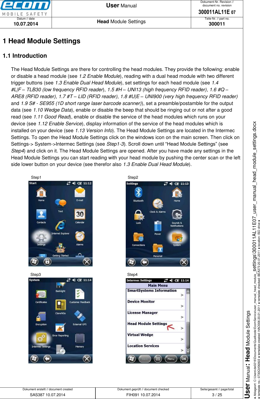
![Datum // date 10.07.2014 Teile-Nr. // part no. 300011 Dokument-Nr. Revision // document no. revision 300011AL11E 07 Head Module Settings User Manual Seite/gesamt // page/total 15 / 25 Dokument erstellt // document created SAS387 10.07.2014 Dokument geprüft // document checked FIH091 10.07.2014 User Manual: Head Module Settings ● Ablageort: C:\Users\de0216\Documents\Quellcode\EcomService\user_manual_head_module_settings\300011AL11E07_user_manual_head_module_settings.docx ● template no.: 0730QV06A03 ● template created: HAO006 20.01.2011 ● template checked: BEA373 20.01.2011 ● location: ISO drive ● Aim Code ID Character of a barcode. Each AIM Code Identifier contains the string “]cm”: ] = Flag Character c = Code Character m = Modifier Character Possible Code Characters (c): A = Code 39 C = Code 128 E = UPC/EAN F = Codabar G = Code 93 H = Code 11 I = Interleaved 2 of 5 M = MSI S = D2 of 5, IATA 2 of 5 X = Code 39 Trioptic, Bookland EAN e = GS1 DataBar Possible Modifier Characters (m): The modifier character is the sum of the possible option values from the following table. Code Type Option Value Option Code 39 0 No Check character or Full ASCII processing. 1 Reader has checked one check character. 3 Reader has checked and stripped check character. 4 Reader has performed Full ASCII character conversion. 5 Reader has performed Full ASCII character conversion and checked one check character. 7 Reader has performed Full ASCII character conversion and checked and stripped check character. Trioptic Code 39 0 No option specified at this time. Always transmit 0. Code 128 0 Standard data packet. No Function code 1 in first symbol position. 1 Function code 1 in first symbol character position. 2 Function code 1 in second symbol character position. I 2 of 5](https://usermanual.wiki/ecom-instruments/300011GR07.Users-Manual/User-Guide-2416342-Page-15.png)
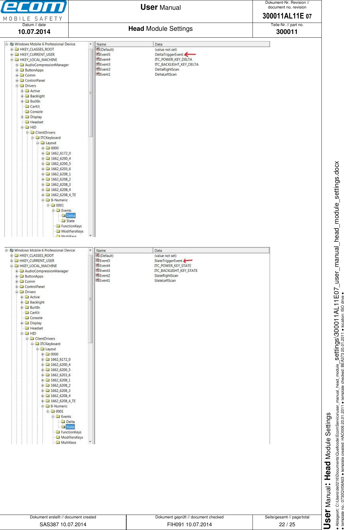
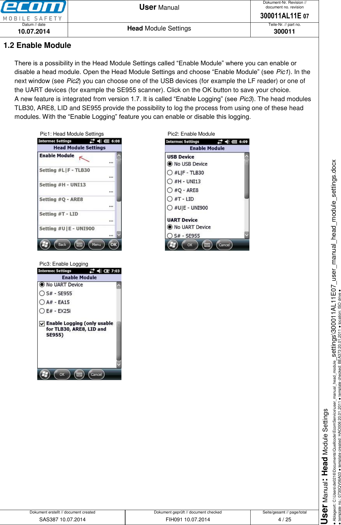
![Datum // date 10.07.2014 Teile-Nr. // part no. 300011 Dokument-Nr. Revision // document no. revision 300011AL11E 07 Head Module Settings User Manual Seite/gesamt // page/total 21 / 25 Dokument erstellt // document created SAS387 10.07.2014 Dokument geprüft // document checked FIH091 10.07.2014 User Manual: Head Module Settings ● Ablageort: C:\Users\de0216\Documents\Quellcode\EcomService\user_manual_head_module_settings\300011AL11E07_user_manual_head_module_settings.docx ● template no.: 0730QV06A03 ● template created: HAO006 20.01.2011 ● template checked: BEA373 20.01.2011 ● location: ISO drive ● 2.2 Map a button on named events to catch the button by software There is a possibility to catch a button to indicate if it is pressed or released. Therefor you must do a few steps in the registry: First step is to locate the layout of your USB keypad in the registry of your device. The path to the current active USB keypad is stored in the registry entry “CurrentActiveLayoutKey” which you can find in the following path of your registry: [HKEY_LOCAL_MACHINE\Hardware\DeviceMap\Keydb]. Example: The “CurrentActiveLayoutKey” of a Ci70 numeric keypad is “Drivers\HID\ClientDrivers\ITCKeyboard\Layout\B-Numeric\0001” as you can see in the following picture. Next step is to create named events. You need two events – a delta and a state event. Choose a unique name for the events e.g. “DeltaTriggerEvent” and “StateTriggerEvent”. These two events have to be added to the list of delta and state events in the registry at the path you have located in the first step (“Drivers\HID\ClientDrivers\ITCKeyboard\Layout\B-Numeric\0001”). Create a new string value in the “Events\Delta” folder named “EventX” where X is the next free value and add the name “DeltaTriggerEvent” on it. Create also a new string value in the “Events\State” folder named “EventX” (the X has to be the same value as the X of the “DeltaTriggerEvent”) and add the name “StateTriggerEvent”.](https://usermanual.wiki/ecom-instruments/300011GR07.Users-Manual/User-Guide-2416342-Page-21.png)