ecom instruments 300011GR07 UNI900F1 User Manual 0730QV06A
ecom instruments GmbH UNI900F1 0730QV06A
Contents
- 1. Users Manual
- 2. Regulatory
Users Manual

Datum // date
10.07.2014
Teile-Nr. // part no.
300011
Dokument-Nr. Revision //
document no. revision
300011AL11E 07
Head Module Settings
User Manual
Seite/gesamt // page/total
1 / 25
Dokument erstellt // document created
SAS387 10.07.2014
Dokument geprüft // document checked
FIH091 10.07.2014
User Manual: Head Module Settings
● Ablageort: C:\Users\de0216\Documents\Quellcode\EcomService\user_manual_head_module_settings\300011AL11E07_user_manual_head_module_settings.docx
● template no.: 0730QV06A03 ● template created: HAO006 20.01.2011 ● template checked: BEA373 20.01.2011 ● location: ISO drive ●
User Manual
Head Module Settings

Datum // date
10.07.2014
Teile-Nr. // part no.
300011
Dokument-Nr. Revision //
document no. revision
300011AL11E 07
Head Module Settings
User Manual
Seite/gesamt // page/total
2 / 25
Dokument erstellt // document created
SAS387 10.07.2014
Dokument geprüft // document checked
FIH091 10.07.2014
User Manual: Head Module Settings
● Ablageort: C:\Users\de0216\Documents\Quellcode\EcomService\user_manual_head_module_settings\300011AL11E07_user_manual_head_module_settings.docx
● template no.: 0730QV06A03 ● template created: HAO006 20.01.2011 ● template checked: BEA373 20.01.2011 ● location: ISO drive ●
Table of Contents:
1 Head Module Settings .................................................................................................................... 3
1.1 Introduction ................................................................................................................................ 3
1.2 Enable Module........................................................................................................................... 4
1.3 Enable Dual Head Module ........................................................................................................ 5
1.4 #L|F – TLB30 (low frequency RFID reader) .............................................................................. 5
1.5 #H – UNI13 (high frequency RFID reader) ................................................................................ 6
1.6 #Q – ARE8 (RFID reader) ......................................................................................................... 7
1.7 #T – LID (RFID reader) ............................................................................................................. 8
1.8 #U|E – UNI900 (very high frequency RFID reader) .................................................................. 8
1.9 S# - SE955 (1D short range laser barcode scanner) ................................................................ 9
1.10 Wedge Data........................................................................................................................... 17
1.11 Good Read ............................................................................................................................ 18
1.12 Enable Service ...................................................................................................................... 18
1.13 Version Info ........................................................................................................................... 19
2 Trigger Button Settings ............................................................................................................... 20
2.1 Map the trigger event “OEM Trigger” on a button ................................................................... 20
2.2 Map a button on named events to catch the button by software ............................................ 21
3 OEM GRID ..................................................................................................................................... 25
3.1 OEM Scanner Grid .................................................................................................................. 25
Datum // date
10.07.2014
Teile-Nr. // part no.
300011
Dokument-Nr. Revision //
document no. revision
300011AL11E 07
Head Module Settings
User Manual
Seite/gesamt // page/total
3 / 25
Dokument erstellt // document created
SAS387 10.07.2014
Dokument geprüft // document checked
FIH091 10.07.2014
User Manual: Head Module Settings
● Ablageort: C:\Users\de0216\Documents\Quellcode\EcomService\user_manual_head_module_settings\300011AL11E07_user_manual_head_module_settings.docx
● template no.: 0730QV06A03 ● template created: HAO006 20.01.2011 ● template checked: BEA373 20.01.2011 ● location: ISO drive ●
1 Head Module Settings
1.1 Introduction
The Head Module Settings are there for controlling the head modules. They provide the following: enable
or disable a head module (see 1.2 Enable Module), reading with a dual head module with two different
trigger buttons (see 1.3 Enable Dual Head Module), set settings for each head module (see 1.4
#L|F – TLB30 (low frequency RFID reader), 1.5 #H – UNI13 (high frequency RFID reader), 1.6 #Q –
ARE8 (RFID reader), 1.7 #T – LID (RFID reader), 1.8 #U|E – UNI900 (very high frequency RFID reader)
and 1.9 S# - SE955 (1D short range laser barcode scanner)), set a preamble/postamble for the output
data (see 1.10 Wedge Data), enable or disable the beep that should be ringing out or not after a good
read (see 1.11 Good Read), enable or disable the service of the head modules which runs on your
device (see 1.12 Enable Service), display information of the service of the head modules which is
installed on your device (see 1.13 Version Info). The Head Module Settings are located in the Intermec
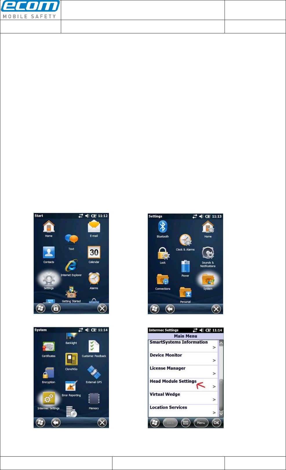
Settings. To open the Head Module Settings click on the windows icon on the main screen. Then click on
Settings-> System->Intermec Settings (see Step1-3). Scroll down until “Head Module Settings” (see
Step4) and click on it. The Head Module Settings are opened. After you have made any settings in the
Head Module Settings you can start reading with your head module by pushing the center scan or the left
side lower button on your device (see therefor also 1.3 Enable Dual Head Module).
Step1 Step2
Step3 Step4
Datum // date
10.07.2014
Teile-Nr. // part no.
300011
Dokument-Nr. Revision //
document no. revision
300011AL11E 07
Head Module Settings
User Manual
Seite/gesamt // page/total
4 / 25
Dokument erstellt // document created
SAS387 10.07.2014
Dokument geprüft // document checked
FIH091 10.07.2014
User Manual: Head Module Settings
● Ablageort: C:\Users\de0216\Documents\Quellcode\EcomService\user_manual_head_module_settings\300011AL11E07_user_manual_head_module_settings.docx
● template no.: 0730QV06A03 ● template created: HAO006 20.01.2011 ● template checked: BEA373 20.01.2011 ● location: ISO drive ●
1.2 Enable Module
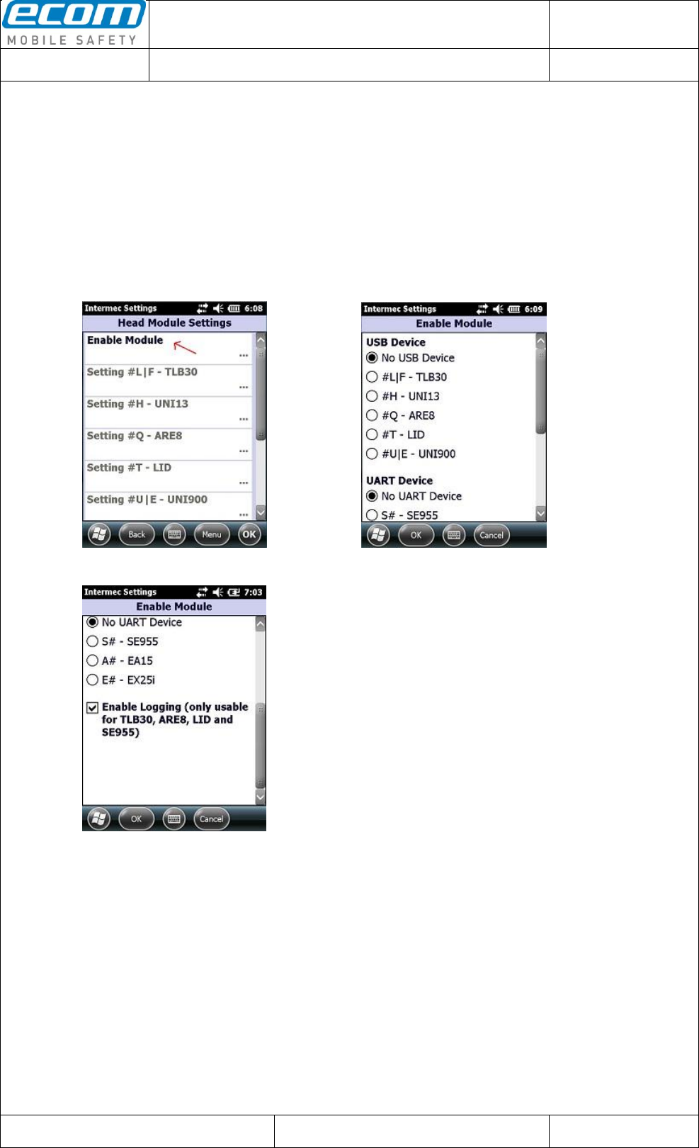
There is a possibility in the Head Module Settings called “Enable Module” where you can enable or
disable a head module. Open the Head Module Settings and choose “Enable Module” (see Pic1). In the
next window (see Pic2) you can choose one of the USB devices (for example the LF reader) or one of
the UART devices (for example the SE955 scanner). Click on the OK button to save your choice.
A new feature is integrated from version 1.7. It is called “Enable Logging” (see Pic3). The head modules
TLB30, ARE8, LID and SE955 provide the possibility to log the process from using one of these head
modules. With the “Enable Logging” feature you can enable or disable this logging.
Pic1: Head Module Settings Pic2: Enable Module
Pic3: Enable Logging
Datum // date
10.07.2014
Teile-Nr. // part no.
300011
Dokument-Nr. Revision //
document no. revision
300011AL11E 07
Head Module Settings
User Manual
Seite/gesamt // page/total
5 / 25
Dokument erstellt // document created
SAS387 10.07.2014
Dokument geprüft // document checked
FIH091 10.07.2014
User Manual: Head Module Settings
● Ablageort: C:\Users\de0216\Documents\Quellcode\EcomService\user_manual_head_module_settings\300011AL11E07_user_manual_head_module_settings.docx
● template no.: 0730QV06A03 ● template created: HAO006 20.01.2011 ● template checked: BEA373 20.01.2011 ● location: ISO drive ●
1.3 Enable Dual Head Module
There is a new feature from version 1.7.2. It is now possible to read with a dual head module by pushing
different trigger buttons. If you choose two head modules, a USB device (e.g. TLB30) and a UART
device (e.g. SE955), you can start reading with the USB device by pushing the center scan button and
with the left side lower button you can start reading with the UART device. In section 1.2 Enable Module
is described how you can select a head module. It is not allowed to choose a USB device together with
EA15 or EX25i. So if you choose a USB device and EA15 or EX25i, the USB device will be disabled and
you can start reading with the EA15 or EX25i by pushing the center scan or the left side lower button. If
you choose only one head module, you can start reading with this head module by pushing the center
scan or the left side lower button.
1.4 #L|F – TLB30 (low frequency RFID reader)
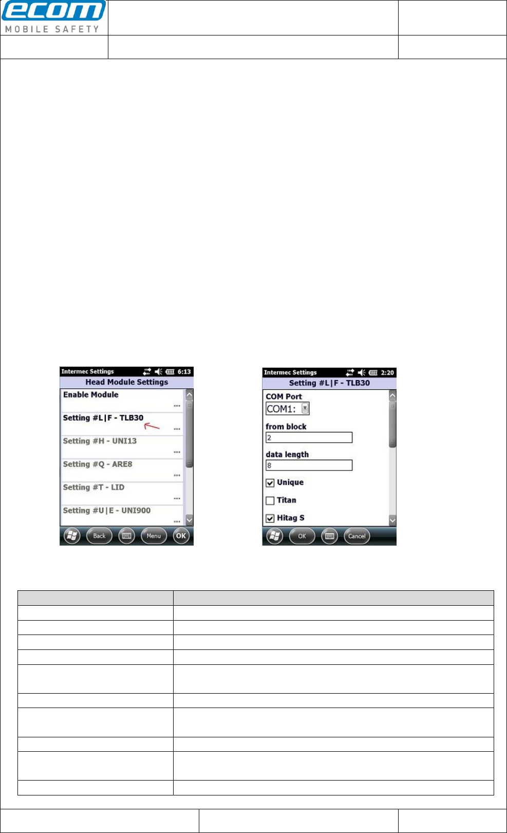
After you have enabled the LF reader through selecting it in the “Enable Module” section in the Head
Module Settings (see 1.2 Enable Module) you are now able to change some settings for the LF reader.
Open the Head Module Settings and choose “Setting #L|F – TLB30” (see Pic4). In the next window (see
Pic5) you can make any changes you want to do for the LF reader. Click on the OK button to save your
changes.
Pic4: Head Module Settings after
enabling the LF reader Pic5: LF reader settings
Explanation of the settings for the #L|F – TLB30:
Setting
Description
COM Port
Serial port of the reader.
from block
Start block address to start reading a TAG.
data length
Length of data to read from a TAG.
Unique
Enable or disable the reading of a Unique TAG.
Titan
Enable or disable the reading of a Titan TAG.
(not implemented at the moment)
HitagS
Enable or disable the reading of a HitagS TAG.
Hitag-2
Enable or disable the reading of a Hitag-2 TAG.
(not implemented at the moment)
Zoodiac
Enable or disable the reading of a Zoodiac TAG.
Q5
Enable or disable the reading of a Q5 TAG.
(not implemented at the moment)
Tiris
Enable or disable the reading of a Tiris TAG.
Datum // date
10.07.2014
Teile-Nr. // part no.
300011
Dokument-Nr. Revision //
document no. revision
300011AL11E 07
Head Module Settings
User Manual
Seite/gesamt // page/total
6 / 25
Dokument erstellt // document created
SAS387 10.07.2014
Dokument geprüft // document checked
FIH091 10.07.2014
User Manual: Head Module Settings
● Ablageort: C:\Users\de0216\Documents\Quellcode\EcomService\user_manual_head_module_settings\300011AL11E07_user_manual_head_module_settings.docx
● template no.: 0730QV06A03 ● template created: HAO006 20.01.2011 ● template checked: BEA373 20.01.2011 ● location: ISO drive ●
timeout for reading (in seconds)
Timeout for reading a TAG (a value from 1 to 25 seconds is
allowed).
Output Data
Format of the output data (HEX or ASCII).
1.5 #H – UNI13 (high frequency RFID reader)
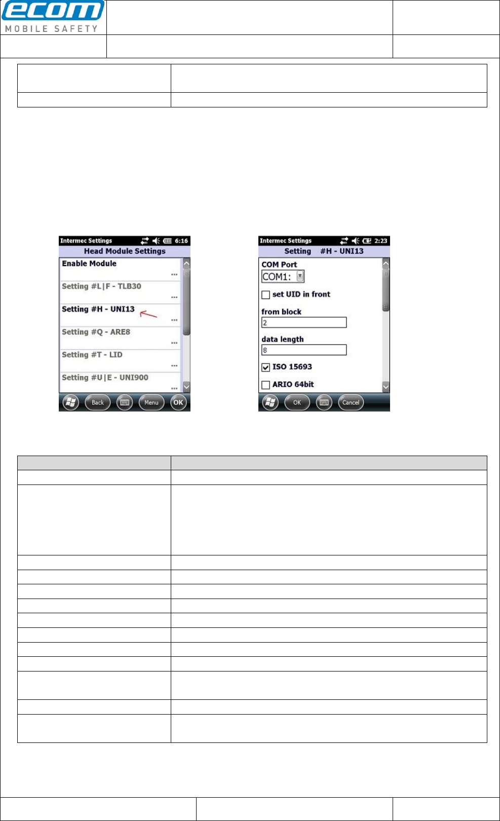
To make some changes for the HF reader, enable the reader in the “Enable Module” section in the Head
Module Settings. Then click on “Setting #H – UNI13” (see Pic6). In the next window (see Pic7) make
your changes you want to do for the HF reader and save them by clicking the OK button.
Pic6: Head Module Settings after
enabling the HF reader Pic7: HF reader settings
Explanation of the settings for the #H – UNI13:
Setting
Description
COM Port
Serial port of the reader.
set UID in front
Enable or disable that the UID of a TAG should be put in front of the
read data.
Note: When this option is enabled and “data length” is set higher
than 0 and reading of data from a TAG failed, the UID of the TAG
will be output alone.
from block
Start block address to start reading a TAG.
data length
Length of data to read from a TAG.
ISO 15693
Enable or disable ISO 15693 transponders.
ARIO 64bit
Enable or disable ARIO 64bit system.
ICODE UID
Enable or disable ICODE UID system.
ICODE 1
Enable or disable ICODE 1 transponders.
Mifare
Enable or disable Mifare transponders.
Pico-Tag
Enable or disable Pico-Tag transponders.
timeout for reading (in seconds)
Timeout for reading a TAG (a value from 1 to 25 seconds is
allowed).
Output Data
Format of the output data (HEX or ASCII).
change high byte with low byte
Enable or disable the changing from high byte with low byte of the
output data.
Datum // date
10.07.2014
Teile-Nr. // part no.
300011
Dokument-Nr. Revision //
document no. revision
300011AL11E 07
Head Module Settings
User Manual
Seite/gesamt // page/total
7 / 25
Dokument erstellt // document created
SAS387 10.07.2014
Dokument geprüft // document checked
FIH091 10.07.2014
User Manual: Head Module Settings
● Ablageort: C:\Users\de0216\Documents\Quellcode\EcomService\user_manual_head_module_settings\300011AL11E07_user_manual_head_module_settings.docx
● template no.: 0730QV06A03 ● template created: HAO006 20.01.2011 ● template checked: BEA373 20.01.2011 ● location: ISO drive ●
Note:
Head modules with the labels NH-UNI13-AB and SH-SE955-UNI13-AB are able to read the UID and
data from a Mifare NFC TAG. Head modules with the labels NH-UNI13-AA and SH-SE955-UNI13-AA
are just able to read the UID of a Mifare TAG. For the head modules with an “AA” it is recommended to
set the option “data length” to 0 and it is necessary to enable the “set UID in front” option in the head
module settings. If you want to read a Mifare TAG with an NH-UNI13-AA or SH-SE955-UNI13-AA it is
also recommended to enable only the Mifare transponder in the head module settings and to disable all
other transponders.
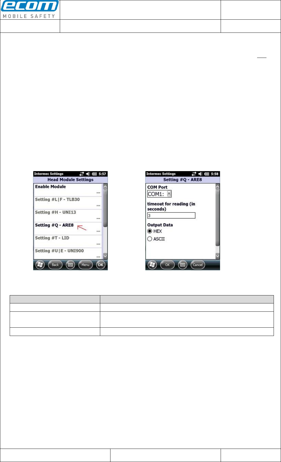
1.6 #Q – ARE8 (RFID reader)
To make some changes for the ARE Trovan reader, enable the reader in the “Enable Module” section in
the Head Module Settings. Then click on “Setting #Q – ARE8” (see Pic8). In the next window (see Pic9)
make your changes you want to do for the ARE Trovan reader and save them by clicking the OK button.
Pic8: Head Module Settings after
enabling the ARE Trovan reader Pic9: ARE Trovan reader settings
Explanation of the settings for the #Q – ARE8:
Setting
Description
COM Port
Serial port of the reader.
timeout for reading (in seconds)
Timeout for reading a TAG (a value from 1 to 25 seconds is
allowed).
Output Data
Format of the output data (HEX or ASCII).
Datum // date
10.07.2014
Teile-Nr. // part no.
300011
Dokument-Nr. Revision //
document no. revision
300011AL11E 07
Head Module Settings
User Manual
Seite/gesamt // page/total
8 / 25
Dokument erstellt // document created
SAS387 10.07.2014
Dokument geprüft // document checked
FIH091 10.07.2014
User Manual: Head Module Settings
● Ablageort: C:\Users\de0216\Documents\Quellcode\EcomService\user_manual_head_module_settings\300011AL11E07_user_manual_head_module_settings.docx
● template no.: 0730QV06A03 ● template created: HAO006 20.01.2011 ● template checked: BEA373 20.01.2011 ● location: ISO drive ●
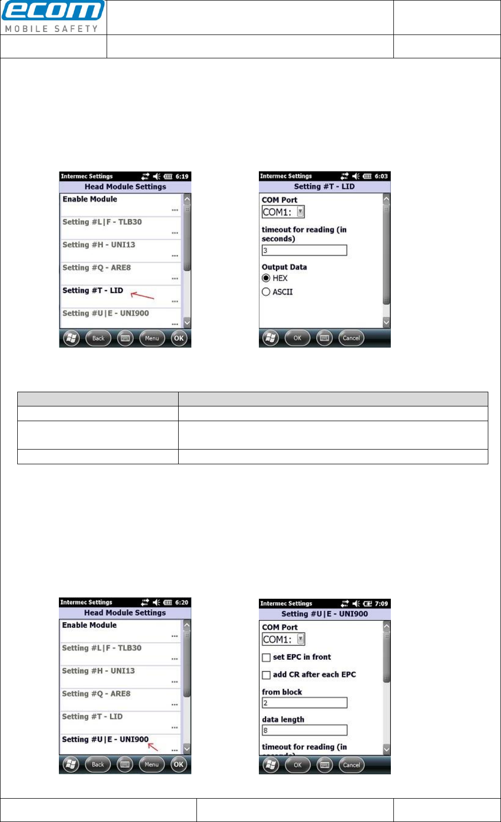
1.7 #T – LID (RFID reader)
To make some changes for the LID Trovan reader, enable the reader in the „Enable Module“ section in
the Head Module Settings. Then click on “Setting #T - LID“ (see Pic10). In the next window (see Pic11)
make your changes you want to do for the LID Trovan reader and save them by clicking the OK button.
Pic10: Head Module Settings after
enabling the LID Trovan reader Pic11: LID Trovan reader settings
Explanation of the settings for the #T – LID:
Setting
Description
COM Port
Serial port of the reader.
timeout for reading (in seconds)
Timeout for reading a TAG (a value from 1 to 25 seconds is
allowed).
Output Data
Format of the output data (HEX or ASCII).
1.8 #U|E – UNI900 (very high frequency RFID reader)
To make some changes for the UHF reader, enable the reader in the “Enable Module” section in the
Head Module Settings. Then click on “Setting #U|E – UNI900” (see Pic12). In the next window (see
Pic13) make your changes you want to do for the UHF reader and save them by clicking the OK button.
Pic12: Head Module Settings after
enabling the UHF reader Pic13: UHF reader settings
Datum // date
10.07.2014
Teile-Nr. // part no.
300011
Dokument-Nr. Revision //
document no. revision
300011AL11E 07
Head Module Settings
User Manual
Seite/gesamt // page/total
9 / 25
Dokument erstellt // document created
SAS387 10.07.2014
Dokument geprüft // document checked
FIH091 10.07.2014
User Manual: Head Module Settings
● Ablageort: C:\Users\de0216\Documents\Quellcode\EcomService\user_manual_head_module_settings\300011AL11E07_user_manual_head_module_settings.docx
● template no.: 0730QV06A03 ● template created: HAO006 20.01.2011 ● template checked: BEA373 20.01.2011 ● location: ISO drive ●
Explanation of the settings for the #U|E – UNI900:
Setting
Description
COM Port
Serial port of the reader.
set EPC in front
Enable or disable that the EPC of a TAG should be put in front of
the read data.
add CR after each EPC
If more than one TAG is identified and this option is enabled, a
carriage return is inserted after each EPC of a TAG.
from block
Start block address to start reading a TAG.
data length
Length of data to read from a TAG.
timeout for reading (in seconds)
Timeout for reading a TAG (a value from 1 to 25 seconds is
allowed).
Output Data
Format of the output data (HEX or ASCII).
change high byte with low byte
Enable or disable the changing from high byte with low byte of the
output data.
Power adjustment
Power adjustment of the reader. A setting from 6 to 27 dB is
available.
Note:
If more than one TAG is identified, only the EPCs of the TAGs are output. In this case the option set
EPC in front has to be enabled. If this option is disabled, a sound is ringing out if more than one TAG is
identified and nothing will be output.
In the case that more than one TAG is identified, no data is read from the TAGs so the options from
block and data length have no effect in this situation.
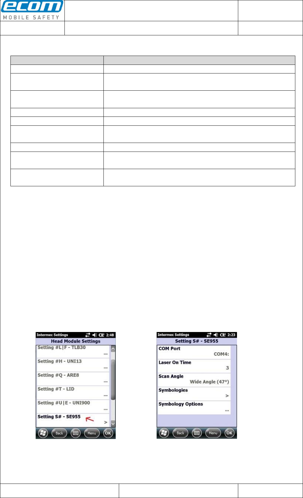
1.9 S# - SE955 (1D short range laser barcode scanner)
To make some changes for the SE955 scanner, enable the scanner in the “Enable Module” section in the
Head Module Settings. Then click on “Setting S# – SE955” (see Pic14). In the next window (see Pic15)
make your changes you want to do for the SE955 scanner and save them by clicking the OK button.
Pic14: Head Module Settings after
enabling the SE955 scanner Pic15: SE955 scanner settings

Datum // date
10.07.2014
Teile-Nr. // part no.
300011
Dokument-Nr. Revision //
document no. revision
300011AL11E 07
Head Module Settings
User Manual
Seite/gesamt // page/total
10 / 25
Dokument erstellt // document created
SAS387 10.07.2014
Dokument geprüft // document checked
FIH091 10.07.2014
User Manual: Head Module Settings
● Ablageort: C:\Users\de0216\Documents\Quellcode\EcomService\user_manual_head_module_settings\300011AL11E07_user_manual_head_module_settings.docx
● template no.: 0730QV06A03 ● template created: HAO006 20.01.2011 ● template checked: BEA373 20.01.2011 ● location: ISO drive ●
Explanation of the settings for the S# - SE955:
Setting
Description
COM Port
Serial port of the scanner.
Laser On Time
Timeout for scanning a barcode.
Scan Angle
Angle for scanning a barcode (allowed values are
narrow or wide).
Symbologies->UPC/EAN
UPC-A
Enable or disable decoding of UPC-A barcodes.
UPC-E
Enable or disable decoding of UPC-E barcodes.
UPC-E1
Enable or disable decoding of UPC-E1 barcodes.
EAN-8
Enable or disable decoding of EAN-8 barcodes.
EAN-13
Enable or disable decoding of EAN-13 barcodes.
Bookland EAN
Enable or disable decoding of Bookland EAN
barcodes.
Decode UPC/EAN Supplementals
Ignore = Decodes UPC/EAN barcodes and ignores
potential supplemental characters.
Decode = Decodes only UPC/EAN barcodes with
supplemental characters.
Autodisriminate = see “Decode UPC/EAN
Supplemental Redundancy”
Smart Supplemental Mode = EAN-13 barcodes with
a prefix of ‘378’, ‘379’ or ‘978’ and supplemental
characters are decoded with the supplemental
characters. For all other UPC/EAN barcodes, the
supplemental characters are ignored.
378/379 Supplemental Mode = EAN-13 barcodes
with a prefix of ‘378’ or ‘379’ and supplemental
characters are decoded with the supplemental
characters. For all other UPC/EAN barcodes, the
supplemental characters are ignored.
978 Supplemental Mode = EAN-13 barcodes with a
prefix of ‘978’ and supplemental characters are
decoded with the supplemental characters. For all
other UPC/EAN barcodes, the supplemental
characters are ignored.
Decode UPC/EAN Supplemental Redundancy
This setup indicates how many times a barcode
without supplemental characters is decoded before
transmission (a value from 2 to 30 is allowed).
The option “Autodisriminate” must be selected.
Transmit UPC-A Check Digit
Enable or disable whether the check digit of a UPC-
A barcode should be transmitted.
Transmit UPC-E Check Digit
Enable or disable whether the check digit of a UPC-
E barcode should be transmitted.
Transmit UPC-E1 Check Digit
Enable or disable whether the check digit of a UPC-
E1 barcode should be transmitted.
UPC-A Preamble
No Preamble = Transmit no preamble for UPC-A.
System Character = Transmit system character as
preamble for UPC-A.
System Char. + Country Code = Transmit system
character and country code as preamble for UPC-A.

Datum // date
10.07.2014
Teile-Nr. // part no.
300011
Dokument-Nr. Revision //
document no. revision
300011AL11E 07
Head Module Settings
User Manual
Seite/gesamt // page/total
11 / 25
Dokument erstellt // document created
SAS387 10.07.2014
Dokument geprüft // document checked
FIH091 10.07.2014
User Manual: Head Module Settings
● Ablageort: C:\Users\de0216\Documents\Quellcode\EcomService\user_manual_head_module_settings\300011AL11E07_user_manual_head_module_settings.docx
● template no.: 0730QV06A03 ● template created: HAO006 20.01.2011 ● template checked: BEA373 20.01.2011 ● location: ISO drive ●
UPC-E Preamble
No Preamble = Transmit no preamble for UPC-E.
System Character = Transmit system character as
preamble for UPC-E.
System Char. + Country Code = Transmit system
character and country code as preamble for UPC-E.
UPC-E1 Preamble
No Preamble = Transmit no preamble for UPC-E1.
System Character = Transmit system character as
preamble for UPC-E1.
System Char. + Country Code = Transmit system
character and country code as preamble for UPC-
E1.
Convert UPC-E to A
Enable or disable conversion of UPC-E barcode
data into UPC-A format. After conversion, the
settings of UPC-A has an effect on the scanned
UPC-E barcode (e.g. “Transmit UPC-A Check
Digit”, “UPC-A Preamble”).
Convert UPC-E1 to A
Enable or disable conversion of UPC-E1 barcode
data into UPC-A format. After conversion, the
settings of UPC-A has an effect on the scanned
UPC-E1 barcode (e.g. “Transmit UPC-A Check
Digit”, “UPC-A Preamble”).
Security Level
Level0 = This level offers an acceptable security for
most of the UPC/EAN barcodes.
Level1 = Select this level if misreads of barcodes
occur and the misreads are confined to specific
characters (e.g. 1, 2, 3, 4).
Level2 = If misreads occur and the misreads aren't
confined to the specific characters, select this level.
Level3 = Choose this level if misreads still occur
after choosing the Level2.
UCC Coupon Extended Code
Enable or disable decoding of UCC Coupon
Extended Code barcodes.
Symbologies->Code128
Enable Code 128
Enable or disable decoding of Code 128 barcodes.
UCC/EAN 128
Enable or disable decoding of UCC/EAN 128
barcodes.
ISBT 128
Enable or disable decoding of ISBT 128 barcodes.
Symbologies->Code 39
Enable Code 39
Enable or disable decoding of Code 39 barcodes.
Trioptic Code 39
Enable or disable decoding of Trioptic Code 39
barcodes.
Convert Code 39 to Code 32
Enable or disable converting Code 39 to Code 32.
(“Enable Code 39” must be enabled for this option)
Code 32 Prefix
Enable or disable adding the prefix ‘A’ to a Code 32
barcode.
(“Convert Code 39 to Code 32” must be enabled for
this option)
Length Options
one discrete length = Decodes only those Code 39
barcodes that have the specified length.
two discrete lengths = Decodes only those Code 39
barcodes that have one of the two specified

Datum // date
10.07.2014
Teile-Nr. // part no.
300011
Dokument-Nr. Revision //
document no. revision
300011AL11E 07
Head Module Settings
User Manual
Seite/gesamt // page/total
12 / 25
Dokument erstellt // document created
SAS387 10.07.2014
Dokument geprüft // document checked
FIH091 10.07.2014
User Manual: Head Module Settings
● Ablageort: C:\Users\de0216\Documents\Quellcode\EcomService\user_manual_head_module_settings\300011AL11E07_user_manual_head_module_settings.docx
● template no.: 0730QV06A03 ● template created: HAO006 20.01.2011 ● template checked: BEA373 20.01.2011 ● location: ISO drive ●
lengths.
lengths within a range = Decodes only those
Code 39 barcodes that have a length which lies in
the specified range.
any length = Decodes Code 39 barcodes of any
length.
Check Digit Verification
Enable or disable the verification of the data of a
Code 39 barcode.
Transmit Check Digit
Enable or disable whether the check digit of a
Code 39 barcode should be transmitted.
Full ASCII Conversion
Enable or disable decoding of Code 39 Full ASCII
barcodes.
Symbologies->Code 93
Enable Code 93
Enable or disable decoding of Code 93 barcodes.
Length Options
one discrete length = Decodes only those Code 93
barcodes that have the specified length.
two discrete lengths = Decodes only those Code 93
barcodes that have one of the two specified
lengths.
lengths within a range = Decodes only those
Code 93 barcodes that have a length which lies in
the specified range.
any length = Decodes Code 93 barcodes of any
length.
Symbologies->Code 11
Enable Code 11
Enable or disable decoding Code 11 barcodes.
Length Options
one discrete length = Decodes only those Code 11
barcodes that have the specified length.
two discrete lengths = Decodes only those Code 11
barcodes that have one of the two specified
lengths.
lengths within a range = Decodes only those
Code 11 barcodes that have a length which lies in
the specified range.
any length = Decodes Code 11 barcodes of any
length.
Check Digit Verification
Disable = Disable the verification of the data of a
Code 11 barcode.
One Check Digit = Enable the verification of the
data of a Code 11 barcode and check for one check
digit.
Two Check Digits = Enable the verification of the
data of a Code 11 barcode and check for two check
digits.
Transmit Check Digit(s)
Enable or disable whether the check digit(s) of a
Code 11 barcode should be transmitted.
Symbologies->Interleaved 2 of 5
Enable Interleaved 2 of 5
Enable or disable decoding Interleaved 2 of 5
barcodes.
Length Options
one discrete length = Decodes only those
Interleaved 2 of 5 barcodes that have the specified

Datum // date
10.07.2014
Teile-Nr. // part no.
300011
Dokument-Nr. Revision //
document no. revision
300011AL11E 07
Head Module Settings
User Manual
Seite/gesamt // page/total
13 / 25
Dokument erstellt // document created
SAS387 10.07.2014
Dokument geprüft // document checked
FIH091 10.07.2014
User Manual: Head Module Settings
● Ablageort: C:\Users\de0216\Documents\Quellcode\EcomService\user_manual_head_module_settings\300011AL11E07_user_manual_head_module_settings.docx
● template no.: 0730QV06A03 ● template created: HAO006 20.01.2011 ● template checked: BEA373 20.01.2011 ● location: ISO drive ●
length.
two discrete lengths = Decodes only those
Interleaved 2 of 5 barcodes that have one of the
two specified lengths.
lengths within a range = Decodes only those
Interleaved 2 of 5 barcodes that have a length
which lies in the specified range.
any length = Decodes Interleaved 2 of 5 barcodes
of any length.
Check Digit Verification
Disable = Disable the verification of the data of an
Interleaved 2 of 5 barcode.
USS Check Digit = Enable the verification of the
data of an Interleaved 2 of 5 barcode by using the
USS (Uniform Symbology Specification) algorithm.
OPCC Check Digit = Enable the verification of the
data of an Interleaved 2 of 5 barcode by using the
OPCC (Optical Product Code Council) algorithm.
Transmit Check Digit
Enable or disable whether the check digit of an
Interleaved 2 of 5 barcode should be transmitted.
Convert Interleaved 2 of 5 to EAN13
Enable or disable conversion of a 14 character
Interleaved 2 of 5 barcode into EAN-13.
(The Interleaved 2 of 5 barcode must have a
leading zero and a valid EAN-13 check digit.)
Symbologies->Discrete 2 of 5
Enable Discrete 2 of 5
Enable or disable decoding Discrete 2 of 5
barcodes.
Length Options
one discrete length = Decodes only those Discrete
2 of 5 barcodes that have the specified length.
two discrete lengths = Decodes only those Discrete
2 of 5 barcodes that have one of the two specified
lengths.
lengths within a range = Decodes only those
Discrete 2 of 5 barcodes that have a length which
lies in the specified range.
any length = Decodes Discrete 2 of 5 barcodes of
any length.
Symbologies->Chinese 2 of 5
Enable Chinese 2 of 5
Enable or disable decoding Chinese 2 of 5
barcodes.
Symbologies->Codabar
Enable Codabar
Enable or disable decoding Codabar barcodes.
Length Options
one discrete length = Decodes only those Codabar
barcodes that have the specified length.
two discrete lengths = Decodes only those Codabar
barcodes that have one of the two specified
lengths.
lengths within a range = Decodes only those
Codabar barcodes that have a length which lies in
the specified range.
any length = Decodes Codabar barcodes of any
length.

Datum // date
10.07.2014
Teile-Nr. // part no.
300011
Dokument-Nr. Revision //
document no. revision
300011AL11E 07
Head Module Settings
User Manual
Seite/gesamt // page/total
14 / 25
Dokument erstellt // document created
SAS387 10.07.2014
Dokument geprüft // document checked
FIH091 10.07.2014
User Manual: Head Module Settings
● Ablageort: C:\Users\de0216\Documents\Quellcode\EcomService\user_manual_head_module_settings\300011AL11E07_user_manual_head_module_settings.docx
● template no.: 0730QV06A03 ● template created: HAO006 20.01.2011 ● template checked: BEA373 20.01.2011 ● location: ISO drive ●
CLSI Editing
Enable or disable removing the start and stop
characters and inserting a space after the first, fifth,
and tenth character of a 14-character Codabar
barcode.
NOTIS Editing
Enable or disable removing the start and stop
characters from a Codabar barcode.
Symbologies->MSI
Enable MSI
Enable or disable decoding MSI barcodes.
Length Options
one discrete length = Decodes only those MSI
barcodes that have the specified length.
two discrete lengths = Decodes only those MSI
barcodes that have one of the two specified
lengths.
lengths within a range = Decodes only those
MSI barcodes that have a length which lies in the
specified range.
any length = Decodes MSI barcodes of any length.
Check Digits
Choose how many check digits exists at the end of
the barcode.
Transmit Check Digit
Enable or disable whether the check digit of a
MSI barcode should be transmitted.
Check Digit Algorithm
If you have selected two check digits (see “Check
Digits”) you must select an algorithm to verify the
data of a MSI barcode.
Symbologies->GS1 DataBar
GS1 DataBar 14
Enable or disable decoding GS1 DataBar 14
barcodes.
GS1 DataBar Limited
Enable or disable decoding GS1 DataBar Limited
barcodes.
GS1 DataBar Expanded
Enable or disable decoding GS1 DataBar
Expanded barcodes.
Convert GS1 DataBar to UPC/EAN
Enable or disable conversion of a GS1 DataBar 14
or GS1 DataBar Limited barcode into UPC/EAN.
If the scanned barcode have a single zero as the
first digit, the leading ‘010’ of the barcode is
removed and the barcode is converted into EAN-13.
If the scanned barcode begins with two or more
zeros but not six zeros, the leading ‘0100’ is
removed and the barcode is converted into UPC-A.
In this case the setting UPC-A Preamble which
transmits the system character and country code
has an effect on the scanned barcode.
Symbology Options
Symbology identifier
Enable or disable outputting a code ID character of
a barcode. A code ID character indicates the code
type of a barcode.
Disable = Disables outputting of a code ID
character.
Aim Code ID Character = Enable outputting of the
Datum // date
10.07.2014
Teile-Nr. // part no.
300011
Dokument-Nr. Revision //
document no. revision
300011AL11E 07
Head Module Settings
User Manual
Seite/gesamt // page/total
15 / 25
Dokument erstellt // document created
SAS387 10.07.2014
Dokument geprüft // document checked
FIH091 10.07.2014
User Manual: Head Module Settings
● Ablageort: C:\Users\de0216\Documents\Quellcode\EcomService\user_manual_head_module_settings\300011AL11E07_user_manual_head_module_settings.docx
● template no.: 0730QV06A03 ● template created: HAO006 20.01.2011 ● template checked: BEA373 20.01.2011 ● location: ISO drive ●
Aim Code ID Character of a barcode. Each AIM
Code Identifier contains the string “]cm”:
] = Flag Character
c = Code Character
m = Modifier Character
Possible Code Characters (c):
A = Code 39
C = Code 128
E = UPC/EAN
F = Codabar
G = Code 93
H = Code 11
I = Interleaved 2 of 5
M = MSI
S = D2 of 5, IATA 2 of 5
X = Code 39 Trioptic, Bookland EAN
e = GS1 DataBar
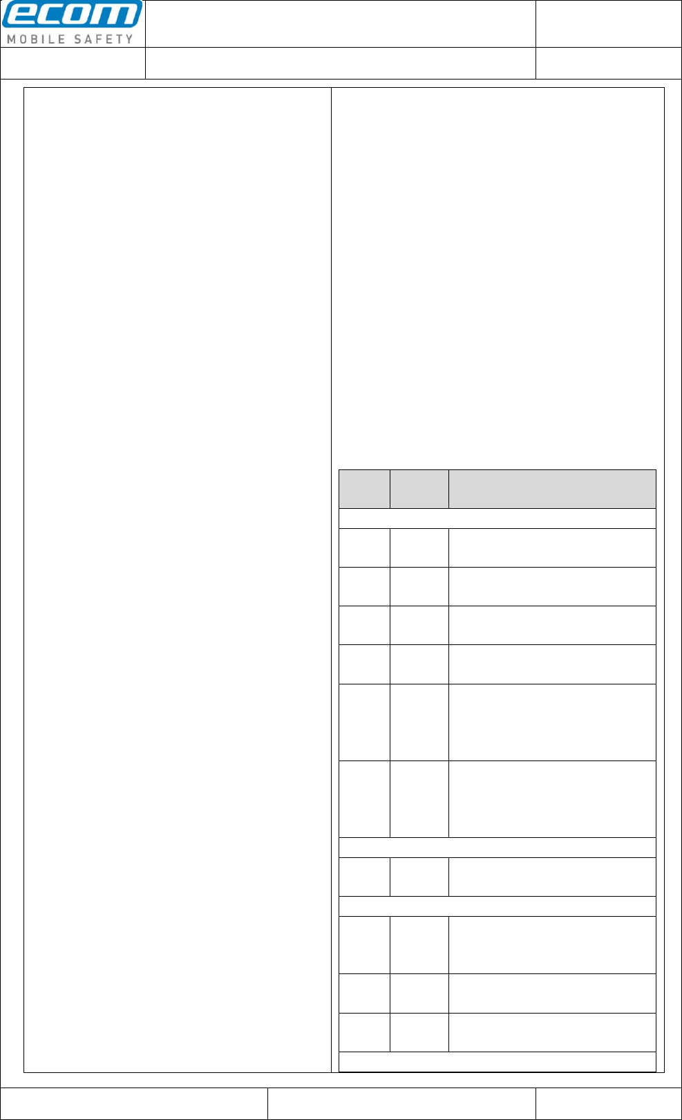
Possible Modifier Characters (m):
The modifier character is the sum of the possible
option values from the following table.
Code
Type
Option
Value
Option
Code 39
0
No Check character or Full
ASCII processing.
1
Reader has checked one
check character.
3
Reader has checked and
stripped check character.
4
Reader has performed Full
ASCII character conversion.
5
Reader has performed Full
ASCII character conversion
and checked one check
character.
7
Reader has performed Full
ASCII character conversion
and checked and stripped
check character.
Trioptic Code 39
0
No option specified at this time.
Always transmit 0.
Code 128
0
Standard data packet. No
Function code 1 in first symbol
position.
1
Function code 1 in first symbol
character position.
2
Function code 1 in second
symbol character position.
I 2 of 5
Datum // date
10.07.2014
Teile-Nr. // part no.
300011
Dokument-Nr. Revision //
document no. revision
300011AL11E 07
Head Module Settings
User Manual
Seite/gesamt // page/total
16 / 25
Dokument erstellt // document created
SAS387 10.07.2014
Dokument geprüft // document checked
FIH091 10.07.2014
User Manual: Head Module Settings
● Ablageort: C:\Users\de0216\Documents\Quellcode\EcomService\user_manual_head_module_settings\300011AL11E07_user_manual_head_module_settings.docx
● template no.: 0730QV06A03 ● template created: HAO006 20.01.2011 ● template checked: BEA373 20.01.2011 ● location: ISO drive ●
0
No check digit processing.
1
Reader has validated check
digit.
3
Reader has validated and
stripped check digit.
Codabar
0
No check digit processing.
1
Reader has checked check
digit.
Code 93
0
No options specified at this
time. Always transmit 0.
MSI
0
Mod 10 check digit checked
and transmitted.
1
Mod 10 check digit checked
but not transmitted.
D 2 of 5
0
No options specified at this
time. Always transmit 0.
UPC/EAN
0
Standard packet in full EAN
country code format, which is
13 digits for UPC-A, UPC-E,
and EAN-13 (not including
supplemental data).
1
Two digit supplement data
only.
2
Five digit supplement data
only.
3
Combined data packet
comprising 13 digits from a
UPC-A ,UPC-E, or EAN-13
symbol and 2 or 5 digits from a
supplemental symbol.
4
EAN-8 data packet.
Bookland EAN
0
No options specified at this
time. Always transmit 0.
Symbol Code ID Character = Enable outputting of
the Symbol Code ID Character of a barcode.
Possible Symbol Code ID Characters:
A = UPC-A, UPC-E, UPC-E1, EAN-8, EAN-13
B = Code 39, Code 32
C = Codabar
D = Code 128, ISBT 128
E = Code 93
F = Interleaved 2 of 5
G = Discrete 2 of 5
J = MSI
Datum // date
10.07.2014
Teile-Nr. // part no.
300011
Dokument-Nr. Revision //
document no. revision
300011AL11E 07
Head Module Settings
User Manual
Seite/gesamt // page/total
17 / 25
Dokument erstellt // document created
SAS387 10.07.2014
Dokument geprüft // document checked
FIH091 10.07.2014
User Manual: Head Module Settings
● Ablageort: C:\Users\de0216\Documents\Quellcode\EcomService\user_manual_head_module_settings\300011AL11E07_user_manual_head_module_settings.docx
● template no.: 0730QV06A03 ● template created: HAO006 20.01.2011 ● template checked: BEA373 20.01.2011 ● location: ISO drive ●
K = UCC/EAN-128
L = Bookland EAN
M = Trioptic Code 39
N = Coupon Code
R = GS1 DataBar-14, GS1 DataBar Limited, GS1
DataBar Expanded
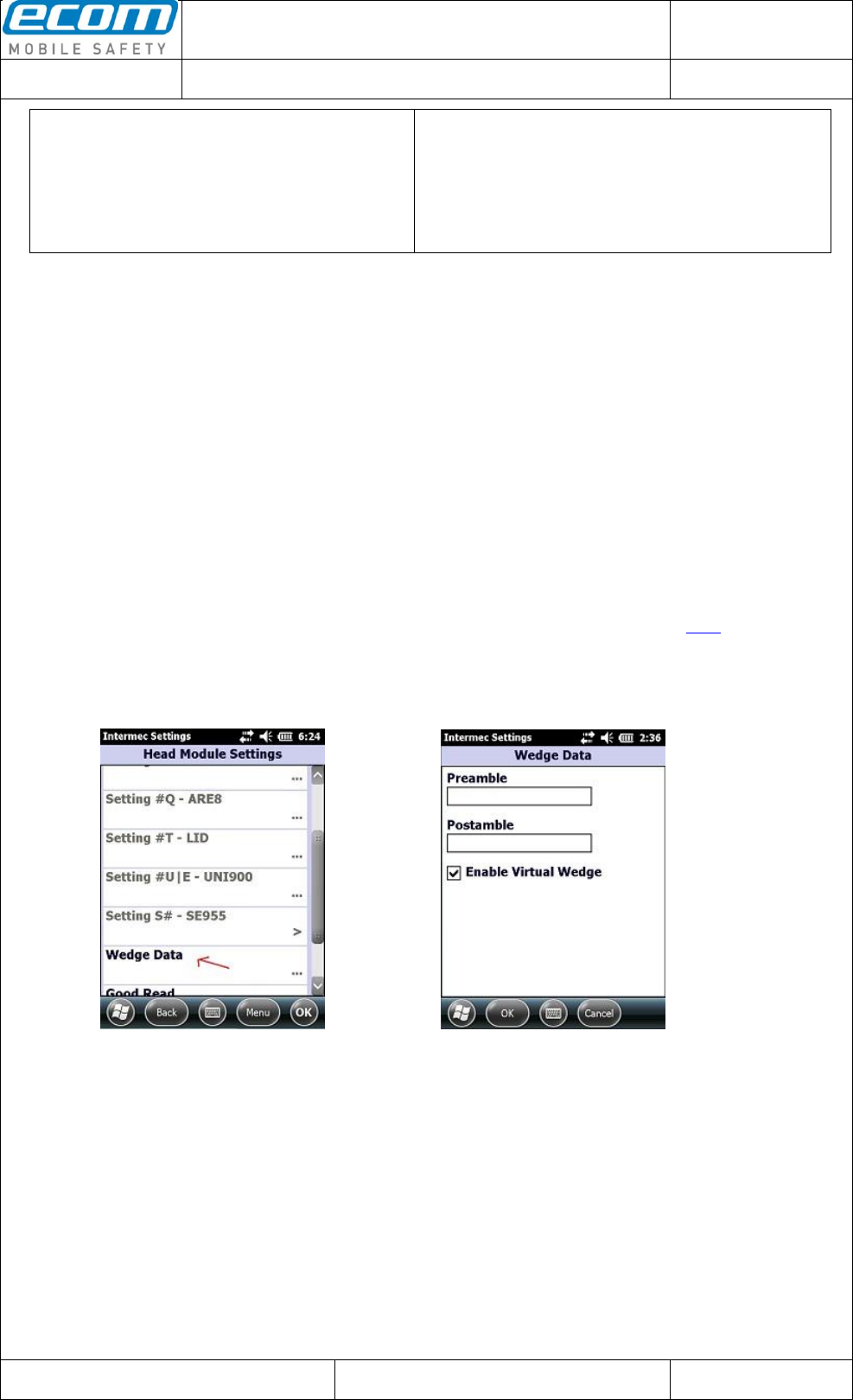
1.10 Wedge Data
To set a preamble or postamble for the data which is read from a head module, open the Head Module
Settings and click on “Wedge Data” (see Pic16). In the next window (see Pic17) set a preamble or
postamble by filling out the corresponding text field and save your settings by clicking the OK button.
Note: You can also set an escape literal for preamble or postamble. The following escape literals are
allowed: \a, \b, \t, \n, \v, \f, \r. A second special feature for preamble/postamble is to set one of the
following codes:
#TAB (sends a tab)
#SPACE (sends a space)
#ENTER (sends an enter)
#xxx (xxx stands for a decimal number between 000 and 127; you can set any ASCII character
for preamble/postamble by using the decimal code of the character -> for example if you set #013
as preamble or postamble a carriage return will be sent (see more examples here))
Another option that you can make in this section of the Head Module Settings is to enable or disable the
Wedge. This means that if you would disable the Wedge, no data will be output.
Pic16: Head Module Settings Pic17: Settings for the Wedge
Datum // date
10.07.2014
Teile-Nr. // part no.
300011
Dokument-Nr. Revision //
document no. revision
300011AL11E 07
Head Module Settings
User Manual
Seite/gesamt // page/total
18 / 25
Dokument erstellt // document created
SAS387 10.07.2014
Dokument geprüft // document checked
FIH091 10.07.2014
User Manual: Head Module Settings
● Ablageort: C:\Users\de0216\Documents\Quellcode\EcomService\user_manual_head_module_settings\300011AL11E07_user_manual_head_module_settings.docx
● template no.: 0730QV06A03 ● template created: HAO006 20.01.2011 ● template checked: BEA373 20.01.2011 ● location: ISO drive ●
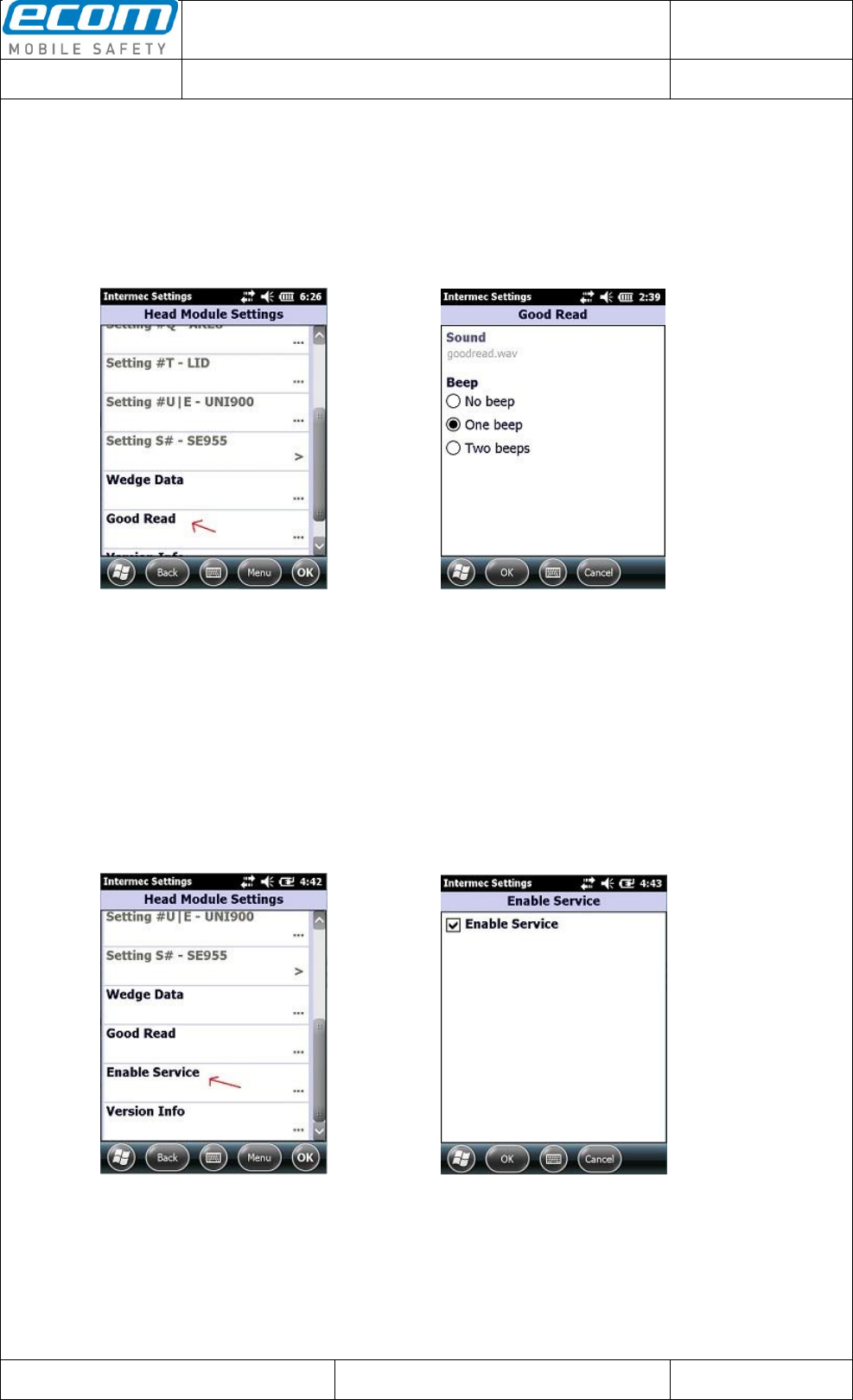
1.11 Good Read
The Head Module Settings provide an option to set a beep for ringing out after a good read. To set this,
open the Head Module Settings and click on “Good Read” (see Pic18). In the next window (see Pic19)
you have the opportunity to set “No beep”, “One beep” or “Two beeps”. Save your setting by clicking the
OK button.
Pic18: Head Module Settings Pic19: Beep options
1.12 Enable Service
A new option is included from version 1.7.5. You are now able to enable or disable the EC_Service. To
set this, open the Head Module Settings and click on “Enable Service” (see Pic20). In the next window
(see Pic21) you can enable or disable the EC_Service by checking or unchecking the checkbox. A
message is shown that you have to confirm the setting by clicking the OK button and that you have to
reboot the device. This has to be done because this setting has only an effect when it is confirmed with
OK and when the device is rebooted!
Pic20: Head Module Settings Pic21: Enable Service
Datum // date
10.07.2014
Teile-Nr. // part no.
300011
Dokument-Nr. Revision //
document no. revision
300011AL11E 07
Head Module Settings
User Manual
Seite/gesamt // page/total
19 / 25
Dokument erstellt // document created
SAS387 10.07.2014
Dokument geprüft // document checked
FIH091 10.07.2014
User Manual: Head Module Settings
● Ablageort: C:\Users\de0216\Documents\Quellcode\EcomService\user_manual_head_module_settings\300011AL11E07_user_manual_head_module_settings.docx
● template no.: 0730QV06A03 ● template created: HAO006 20.01.2011 ● template checked: BEA373 20.01.2011 ● location: ISO drive ●
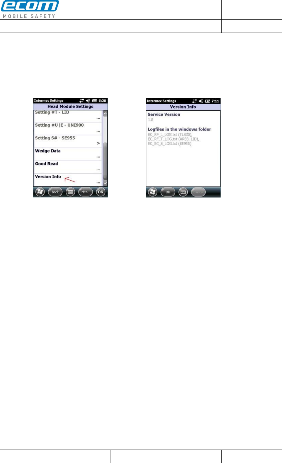
1.13 Version Info
Last point in the Head Module Settings gives you the opportunity to get information about the service of
the head modules which is installed on your device. Open the Head Module Settings and click on
“Version Info” (see Pic22). In the next window you can see the information about the installed service
(see Pic23).
Pic22: Head Module Settings Pic23: Version Info
Datum // date
10.07.2014
Teile-Nr. // part no.
300011
Dokument-Nr. Revision //
document no. revision
300011AL11E 07
Head Module Settings
User Manual
Seite/gesamt // page/total
20 / 25
Dokument erstellt // document created
SAS387 10.07.2014
Dokument geprüft // document checked
FIH091 10.07.2014
User Manual: Head Module Settings
● Ablageort: C:\Users\de0216\Documents\Quellcode\EcomService\user_manual_head_module_settings\300011AL11E07_user_manual_head_module_settings.docx
● template no.: 0730QV06A03 ● template created: HAO006 20.01.2011 ● template checked: BEA373 20.01.2011 ● location: ISO drive ●
2 Trigger Button Settings
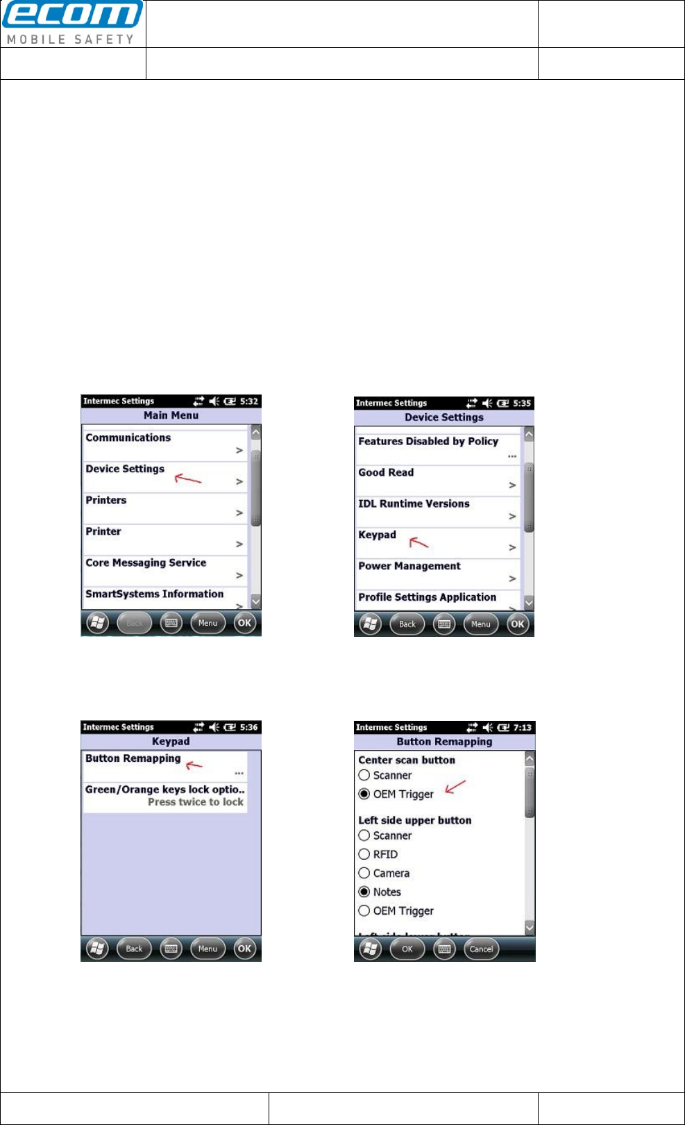
2.1 Map the trigger event “OEM Trigger” on a button
This is necessary to start reading with a head module. There is an event named “OEM Trigger” which
is used in the service of the head modules to start reading with a head module. This event is mapped
on the center scan and the left side lower button by default. You have five opportunities to map this
event on a button: on the center scan button, on the left side upper button, on the left side lower
button, on the right side upper button and on the right side lower button. To map a button on the
event open the Intermec Settings. Therefore you have to click on the windows icon on the main
screen. In the next step you have to click on Settings -> System -> Intermec Settings. To map the
event on a button click on Device Settings -> Keypad -> Button Remapping (see Pic24-Pic26) in the
Intermec Settings. In the next window you can map the “OEM Trigger” event on a button which you
want to use to start reading with a head module (see Pic27).
Pic24: Intermec Settings Pic25: Device Settings
Pic27: Button Remapping
(“OEM Trigger” is mapped on the
center scan and the left side lower
Pic26: Keypad button by default)
Datum // date
10.07.2014
Teile-Nr. // part no.
300011
Dokument-Nr. Revision //
document no. revision
300011AL11E 07
Head Module Settings
User Manual
Seite/gesamt // page/total
21 / 25
Dokument erstellt // document created
SAS387 10.07.2014
Dokument geprüft // document checked
FIH091 10.07.2014
User Manual: Head Module Settings
● Ablageort: C:\Users\de0216\Documents\Quellcode\EcomService\user_manual_head_module_settings\300011AL11E07_user_manual_head_module_settings.docx
● template no.: 0730QV06A03 ● template created: HAO006 20.01.2011 ● template checked: BEA373 20.01.2011 ● location: ISO drive ●
2.2 Map a button on named events to catch the button by software
There is a possibility to catch a button to indicate if it is pressed or released. Therefor you must do a
few steps in the registry:
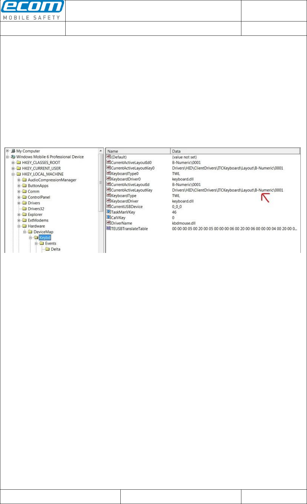
First step is to locate the layout of your USB keypad in the registry of your device. The path to
the current active USB keypad is stored in the registry entry “CurrentActiveLayoutKey” which
you can find in the following path of your registry:
[HKEY_LOCAL_MACHINE\Hardware\DeviceMap\Keydb].
Example: The “CurrentActiveLayoutKey” of a Ci70 numeric keypad is
“Drivers\HID\ClientDrivers\ITCKeyboard\Layout\B-Numeric\0001” as you can see in the
following picture.
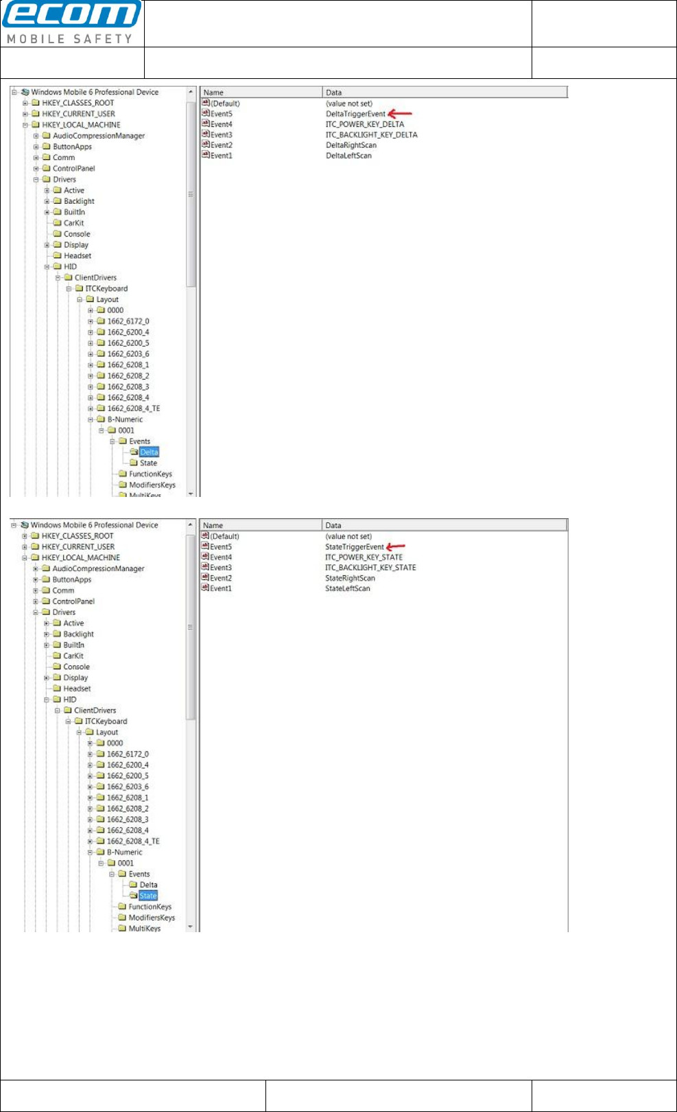
Next step is to create named events. You need two events – a delta and a state event. Choose
a unique name for the events e.g. “DeltaTriggerEvent” and “StateTriggerEvent”. These two
events have to be added to the list of delta and state events in the registry at the path you have
located in the first step (“Drivers\HID\ClientDrivers\ITCKeyboard\Layout\B-Numeric\0001”).
Create a new string value in the “Events\Delta” folder named “EventX” where X is the next free
value and add the name “DeltaTriggerEvent” on it. Create also a new string value in the
“Events\State” folder named “EventX” (the X has to be the same value as the X of the
“DeltaTriggerEvent”) and add the name “StateTriggerEvent”.
Datum // date
10.07.2014
Teile-Nr. // part no.
300011
Dokument-Nr. Revision //
document no. revision
300011AL11E 07
Head Module Settings
User Manual
Seite/gesamt // page/total
22 / 25
Dokument erstellt // document created
SAS387 10.07.2014
Dokument geprüft // document checked
FIH091 10.07.2014
User Manual: Head Module Settings
● Ablageort: C:\Users\de0216\Documents\Quellcode\EcomService\user_manual_head_module_settings\300011AL11E07_user_manual_head_module_settings.docx
● template no.: 0730QV06A03 ● template created: HAO006 20.01.2011 ● template checked: BEA373 20.01.2011 ● location: ISO drive ●
Datum // date
10.07.2014
Teile-Nr. // part no.
300011
Dokument-Nr. Revision //
document no. revision
300011AL11E 07
Head Module Settings
User Manual
Seite/gesamt // page/total
23 / 25
Dokument erstellt // document created
SAS387 10.07.2014
Dokument geprüft // document checked
FIH091 10.07.2014
User Manual: Head Module Settings
● Ablageort: C:\Users\de0216\Documents\Quellcode\EcomService\user_manual_head_module_settings\300011AL11E07_user_manual_head_module_settings.docx
● template no.: 0730QV06A03 ● template created: HAO006 20.01.2011 ● template checked: BEA373 20.01.2011 ● location: ISO drive ●
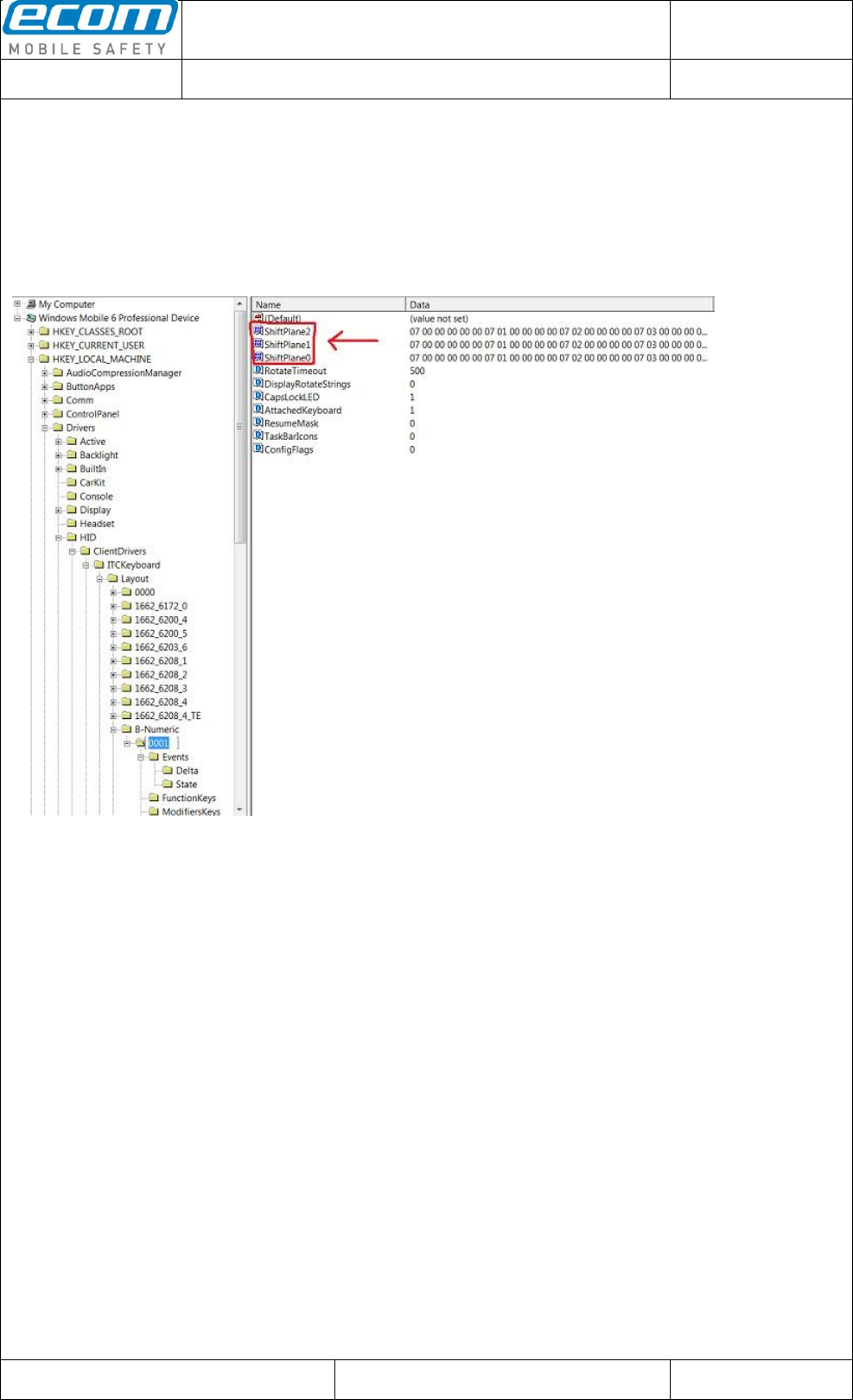
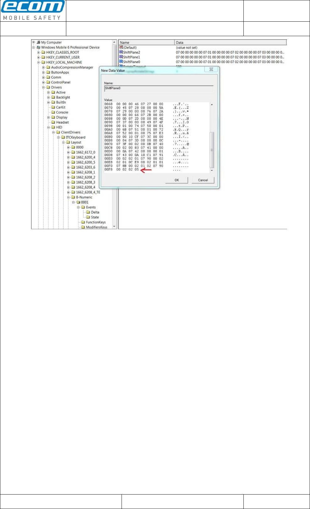
Third step is to map a key to the event index X of the named events “DeltaTriggerEvent” and
“StateTriggerEvent”. You can find the registry entries for the active keys of the keyboard in the
“0001” folder at the path you have located in the first step
(“Drivers\HID\ClientDrivers\ITCKeyboard\Layout\B-Numeric\0001”). There are 3 “ShiftPlanes”
in which the key functionalities are described:
o ShiftPlane0 – Normal – is used if neither Gold nor Aqua key is pressed
o ShiftPlane1 – Gold – is used if the Gold key is pressed
o ShiftPlane2 – Aqua – is used if the Aqua key is pressed
In the described example the events should be mapped to the blue center scan button. For
mapping the center scan button on the events “DeltaTriggerEvent” and “StateTriggerEvent”
you must modify the value for that key in “ShiftPlane0”, “ShiftPlane1” and “ShiftPlane2”. The
value of that key is “07 90 00 02 02 01” where 07 = USB code page, 90 = USB usage, 00 02
02 = flags (02 = non-repeating (key does not auto repeat), 02 = key reacts on a named event),
01 = index of the named event. The only thing which is to do for mapping this key on the
created named events is to change the last value “01” to “05” because the created events
“DeltaTriggerEvent” and “StateTriggerEvent” have the index 5 because of “Event5” in the
registry. So add the new value “07 90 00 02 02 05” at the bottom of the list in the “ShiftPlane0”,
“ShiftPlane1” and “ShiftPlane2”. Now the center scan button is mapped to the created events.
A reboot is necessary after doing the changes in the registry.
Datum // date
10.07.2014
Teile-Nr. // part no.
300011
Dokument-Nr. Revision //
document no. revision
300011AL11E 07
Head Module Settings
User Manual
Seite/gesamt // page/total
24 / 25
Dokument erstellt // document created
SAS387 10.07.2014
Dokument geprüft // document checked
FIH091 10.07.2014
User Manual: Head Module Settings
● Ablageort: C:\Users\de0216\Documents\Quellcode\EcomService\user_manual_head_module_settings\300011AL11E07_user_manual_head_module_settings.docx
● template no.: 0730QV06A03 ● template created: HAO006 20.01.2011 ● template checked: BEA373 20.01.2011 ● location: ISO drive ●
Now all the settings in the registry are done so we can start catching that named events and do
whatever we want if the center scan button is pressed.
Create two events in your application source code by calling the windows function
“CreateEvent()” and set the name of the events to the named events at the registry
(“DeltaTriggerEvent” and “StateTriggerEvent”).
HANDLE hDeltaEvent = CreateEvent(NULL, FALSE, FALSE,
TEXT("DeltaTriggerEvent"));
HANDLE hStateEvent = CreateEvent(NULL, FALSE, FALSE,
TEXT("StateTriggerEvent"));
Next step is to wait for the delta event (“DeltaTriggerEvent”). Use the windows function
“WaitForSingleObject()” or “WaitForMultipleObjects()” to catch the delta event. If the delta
event is caught you must wait for the state event (“StateTriggerEvent”) to check if the center
scan button is pressed or released.
DWORD dwEvent = WaitForSingleObject (hDeltaEvent, INFINITE);
If(dwEvent == WAIT_OBJECT_0)
{
if(WaitForSingleObject(hStateEvent, 10) == WAIT_OBJECT_0)
{
// center scan button is pressed
}
else
{
// center scan button is released
}
}
Do this in a background thread so that the application won’t blocked while waiting that the
center scan button is pressed. If you do no longer need the event functionality close the event
handle with the windows function “CloseHandle()”.
Datum // date
10.07.2014
Teile-Nr. // part no.
300011
Dokument-Nr. Revision //
document no. revision
300011AL11E 07
Head Module Settings
User Manual
Seite/gesamt // page/total
25 / 25
Dokument erstellt // document created
SAS387 10.07.2014
Dokument geprüft // document checked
FIH091 10.07.2014
User Manual: Head Module Settings
● Ablageort: C:\Users\de0216\Documents\Quellcode\EcomService\user_manual_head_module_settings\300011AL11E07_user_manual_head_module_settings.docx
● template no.: 0730QV06A03 ● template created: HAO006 20.01.2011 ● template checked: BEA373 20.01.2011 ● location: ISO drive ●
3 OEM GRID
3.1 OEM Scanner Grid
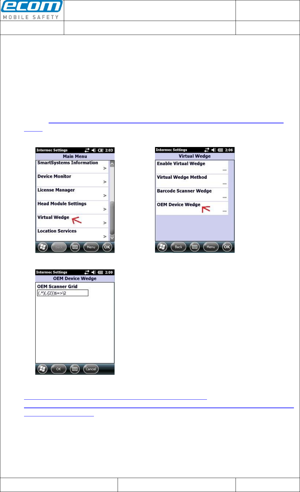
The Scanner Grid offers you the possibility to edit the read data from reading with a head module. To
set a Scanner Grid open the Intermec Settings (Settings->System->Intermec Settings). Scroll down
and click on “Virtual Wedge” (see Pic28). Then click on “OEM Device Wedge” (see Pic29). In the
next window you can set a Scanner Grid (see Pic30). The expression which you can see in Pic30
says that only the last characters of read data are output. For more examples for editing the Scanner
Grid see http://community.intermec.com/t5/General-Development-Developer/GRID-Examples/m-
p/3018.
Pic28: Virtual Wedge Pic29: OEM Device Wedge
Pic30: OEM Scanner Grid
For more Information about editing Scanner Grid see
http://intermec.custhelp.com/app/answers/detail/a_id/7220/kw/GRID and
http://community.intermec.com/t5/forums/searchpage/tab/message?allow_punctuation=true&filter=la
bels&q=grid#message-list