elero Antriebstechnik 282XX0901 RC System for rolling shutters / awnings and venetian blinds User Manual
elero GmbH Antriebstechnik RC System for rolling shutters / awnings and venetian blinds
Contents
- 1. User Manual
- 2. User Manual Annex
User Manual
VarioTel 2-915
No. 282450901, 282460901,
282470901
181221301/0510 EN/FR/ES/PT
elero
Operating instructions
Please take care of the operating instructions!
Instructions d’utilisation
Veuillez conserver les présentes instructions d’utilisation !
Instrucciones de servicio
¡Por favor, conserve estas instrucciones de servicio
Instruções de serviço
Por favor conserve as instruções de serviço !
EN
FR
ES
PT
elero GmbH
Antriebstechnik
Linsenhofer Str. 59–63
D-72660 Beuren
Tel.: +49 (0) 7025-13-01
Fax: +49 (0) 7025-13-212
www.elero.com
info@elero.de
Device explanation
EN-2
EN
Device explanation..................................... EN- 2
Safety instructions/exclusion of liability .............. EN- 3
Scope of supply/ intended use ........................ EN- 5
Bidirectional radio system/unidirectional radio system
EN- 6
Mounting of the wall bracket .......................... EN- 8
Explanation of functions............................... EN- 9
Status LED .......................................... EN- 9
Group control unit ................................... EN- 9
Select button ........................................ EN-10
Programming the transmitter .......................... EN-11
Programming the transmitter/channel ............... EN-11
Programming further transmitters.................... EN-12
Approach limit positions of roller shutter/awning/
venetian blind
.......................................... EN-13
Intermediate positions for roller shutters/awnings/
venetian blinds
......................................... EN-14
Program intermediate position ....................... EN-14
Program ventilation/tilting position ................... EN-15
Approach intermediate position ...................... EN-15
Approach ventilation/tilting position .................. EN-15
Position deletion..................................... EN-16
Delete ventilation/tilting position ..................... EN-16
Deletion of transmitter ................................. EN-17
Deletion of individual transmitters ................... EN-17
Deletion of all transmitters........................... EN-17
Technical data .......................................... EN-17
Battery replacement.................................... EN-18
Cleaning ................................................ EN-18
Disposal ................................................ EN-18
Notes on troubleshooting.............................. EN-19
Notes on repair......................................... EN-19
EC-Declaration of conformity.......................... EN-20
Contents
EN-1
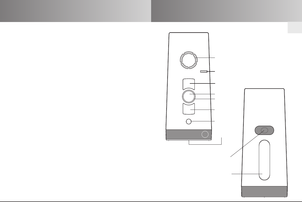
elero
Fixing area for
wall bracket
Programming
button P
UP button
STOP button
Status LED
Channel viewing window
LED window
(automatic/manual
mode)
DOWN button
Select button
Battery
compartment
Back of equipment
on front of device
Safety instructions
EN-4
EN
Safety instructions/exclusion of liability
EN-3
STOP!
Observance of the operating instructions is the
prerequisite for disturbance-free operation and
fulfilment of any claims related to defects.
• Therefore, first read the operating instructions
before you use the device!
• Ensure that the operating instructions are
available to the user in legible form.
• The operator must ensure that the basic safety
measures are observed and fulfilled.
• The operator must have completely read and
understood the operating instructions.
• The following safety and installation instructions
solely refer to the transmitter and not the
accessories and drive.
Exclusion of liability:
It is essential to observe these operating instructions for use if
the VarioTel 2 hand-held transmitter is to be used safely and if
the various product characteristics and performance features are
to be achieved.
elero GmbH assumes no liability for personal injuries, property
damages and financial losses that arise from non-observance of
the operating instructions.
Liability for material defects is excluded in such cases.
CAUTION!
Observe the following safety instructions.
Failure to observe them can lead to bodily injuries!
General
• Never install or commission devices which are
damaged.
• Only use unmodified original elero electrical parts.
• If the device is opened without permission or used in
an improper manner, or if it is incorrectly installed or
operated, there is a risk of damage to persons and
property.
• The device contains small parts which can be
swallowed.
Transport
• If the transmitter arrives in a damaged condition despite
proper packaging, then it must not be commissioned.
Immediately report the damage to the transport
company.
Installation
• Note any country-specific conditions when installing the
device.
• The device may only be used by persons who have
read and understood the operating instructions.
Operation
• Use only in dry rooms.
• If one or more transmitters are used for controlling the
system, its operating range must stay visible during
operation.
• Keep children away from the control units.
• Replace battery only with identical type (LR06;AA).
• Dispose of used batteries properly (collection point).

EN-6
EN
Scope of supply/Intended use
EN-5
Manufacturing note
All the ProLine 2 transmitters are subject to 100% testing by
elero GmbH before delivery.
The ProLine 2 transmitters are made as per the following
guidelines:
• EN 300 220 (electromagnetic compatibility of radio systems)
• ETS 300 683 (Specific conditions for short range radio devices)
• CE mark
Scope of supply
VarioTel 2 (batteries (2 x LR 06; AA) supplied with device)
Wall bracket
2 dowels
2 screws
Intended use
The VarioTel 2 is a multi-channel transmitter. Each channel can be
used unidirectionally (compatible with the existing ProLine
programme) or bidirectionally. The hand-held transmitter may only
be used for controlling roller shutters, venetian blinds and sun
protection systems that are fitted with elero radio receivers.
Other use, or use which goes beyond this use is not considered to
be use for intended purpose.
elero GmbH shall not be liable for:
• Other uses than those described above
• Changes to the device
• Improper use
Please see the technical data contained in these operating
instructions.
Bidirectional radio system/
unidirectional radio system
What does bidirectional radio system mean?
A bidirectional radio system is one that carries out the reliable
transmission of radio signals to a radio receiver and provides
feedback from the radio receiver to the transmitter.
The radio signal can be sent directly to the target receiver. If this
is not possible then the radio signal is forwarded via other
participants until the signal reaches the target receiver.
The target receiver carries out the command and sends a
confirmation back to the transmitter.
The status LED lights up briefly for confirmation.
What is a unidirectional radio system?
A unidirectional radio system provides reliable transmission of
radio signals to a radio receiver.
However, the radio receiver cannot send back a reply to the
transmitter, unlike in a bidirectional radio system.
It is also not possible to pass on the radio signal from one radio
receiver to another.
EN-8
EN
Safety instructions for radio operation
EN-7
Mounting of the wall bracket
CAUTION!
Observe the following safety instructions for radio
operation!
Only use radio systems if they are approved and
can be operated without interference.
• Please note that radio systems must not be operated
in areas with an increased risk of interference
(e.g. hospitals, airports, ....).
• The remote control is only approved for devices and
systems for which any malfunction of the transmitter
or receiver would not result in a risk for persons,
animals or property, or if such a risk is covered by
other safety equipment.
• The operator has no protection whatsoever from
interferences by other radio emitters and local termi-
nals (e.g. also from radio systems), that are normally
used on the same frequency range.
• The range of the radio signal is limited by the
government and the built environment.
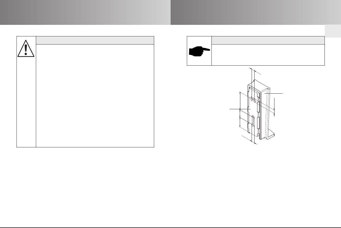
Mounting of the wall bracket
1. Use the drilling template on the inside of the packing box.
2. Remove the cover from the box.
3. Fix the drilling template to the wall.
4. Drill the holes in the wall.
5. Remove the drilling template.
6. Push the bracket upper and lower parts to separate them.
7. Fix the bracket lower part onto the wall using the screws and
dowels provided.
8. Push the bracket upper part from above onto the bracket lower
part until it is locked into place.
4,5
10, 5 24,75
4,5
4,5
13, 5
NOTICE!
The wall bracket has to be fixed so that the drill
holes don’t touch any electrical lines.
Check this before installation.
Bracket upper part
Bracket lower part

Explanation of functions
EN-10
Select button (channel selection button, AUTO switching
button)
Up to 5 channels can be selected by pressing the Select button
briefly.
The individual channels are displayed by illumination of the
associated channel viewing windows.
An additional channel is reserved for the central command. This
is allocated automatically. All five channel viewing windows
illuminate to indicate the central command.
Pressing the Select button briefly allows the current status of
the programmed receiver and the channel of the hand-held
transmitter to be queried.
Longer pressing (approx. 1 sec.) of the Select button switches off
the automatic mode. The LED window lights up red.
WThe receiver now only executes manual travel commands.
Longer pressing (approx. 1 sec.) of the Select button again
switches on the automatic mode. The LED window lights up green.
WThe receiver now executes automatic and manual travel
commands.
Status LED
A radio signal is displayed by the illumination of the Status LED
(LED ring around the STOP button).
The status LED can display three different colours:
– Orange: Transmit signal is being sent
(bidirectional radio operation)
– Green: Transmit signal is being sent
(unidirectional radio operation)
Positive reply from the transmitted signal
(bidirectional radio operation)
– Red: No answer from receiver
(bidirectional radio operation)
The transmitting power or the radio range will be reduced through
the reduction in the performance of the battery.
If the status LED no longer illuminates upon pressing the button,
the batteries have to be replaced.
Please see these instructions for changing the battery.
(Wsee battery replacement)
Group control unit
A group is understood to mean the control of several receivers at
the same time. The selected group is controlled by a travel
command.
With VarioTel 2 you can use all five radio channels to control a
group.
The central channel (all five channel viewing windows light up
simultaneously) controls all five radio channels at the same time.
EN
Explanation of functions
EN-9
EN-12
EN
Programming the transmitter
EN-11
Programming additional transmitters
Programming additional transmitters
NOTICE!
If several receivers are connected to the same
feed line, then all are simultaneously ready to pro-
gram. The blinds start a “random” brief up/down
travel. The longer you wait with the programming
the greater will be the offset.
You can stop the brief up/down travel by briefly
pressing the STOP button on a transmitter which
has already been programmed. The programming
procedure is interrupted.
The transmitter assignment can now be made
without having to disconnect individual receivers.
If the blind travels in the wrong direction, delete
the transmitter and reprogram it.
(Wsee Deletion of transmitter)
To programme additional transmitters in one receiver, please proceed
as follows:
1. Press the UP, DOWN and the programming button P(back of
device) simultaneously (for 3 sec.) on a transmitter, which has
already been programmed to the receiver. The status LED lights
up briefly.
Push the programming button P(on back of device) on the new
transmitter to be programmed until the status LED lights up briefly.
2. Press the UP button immediately after the start of upward travel
(max. 1 second).
The status LED lights up briefly. The blind will stop – start moving
again – stop and then move in the DOWN direction.
3. Press the DOWN button immediately after the start of downward
travel (max. 1 second).
The status LED lights up briefly. The blind will stop.
The transmitter or the transmitter channel has been programmed.
1. With electrical, previously installed receivers, turn the safety
fuse off and after a few seconds on again.
The receiver is now in programming mode for about
5 minutes.
2. Press the programming button Pon the back of the device
briefly (approx 1 sec).
The shutter/blind moves up and down automatically after
approx. 2 minutes to show that the receiver is in program-
ming mode.
3. Press the UP button immediately after the start of upward
travel (max. 1 second).
The status LED lights up briefly.
The blind will stop – start moving again – stop and then move
in the DOWN direction.
4. Press the DOWN button immediately after the start of
downward travel (max. 1 second).
The status LED lights up briefly.
The blind/shutter will stop.
The VarioTel 2 is now programmed.
Programming the transmitter
PREREQUISITE!
The receiver must be installed.
Note that the radio range to the receiver is limited
during programming.
Position yourself in front of the shutter/blind for
programming.
!
NOTICE!
If the blind does not stop, the programming process
must be repeated.
EN-14
EN
Approach limit positions
Roller shutter/awning/venetian blind
EN-13
Intermediate positions for roller shutters/
awnings/venetian blinds
PREREQUISITE!
The transmitter/transmitter channel has been
programmed.
The end positions of the drive have been set.
!
Approach lower end position (roller shutter/awning)
Press the DOWN button briefly.
The blind approaches the lower end position/the awning moves
out.
Approach lower end position (venetian blind)
Press the DOWN button until the status LED lights up briefly.
The blind approaches the lower end position.
Press the DOWN button briefly (jogging mode); the blind moves
a short distance and stops again.
Approach upper end position (roller shutter/awning)
Press the UP button briefly.
The blind approaches the upper end position/the awning retracts.
Approach upper end position (venetian blind)
Press the UP button until the status LED lights up briefly.
The blind approaches the upper end position.
Press the UP button briefly (jogging mode); the blind moves a
short distance and stops again.
Program intermediate position
1. Move the blind as far as necessary in the UP direction until
the ventilation gaps open or the slats are inverted.
Hold down the UP button until the desired position is reached.
2. In addition press the STOP button.
The blind/shutter will stop. The status LED lights up briefly.
The intermediate position/ventilation position is now
programmed.
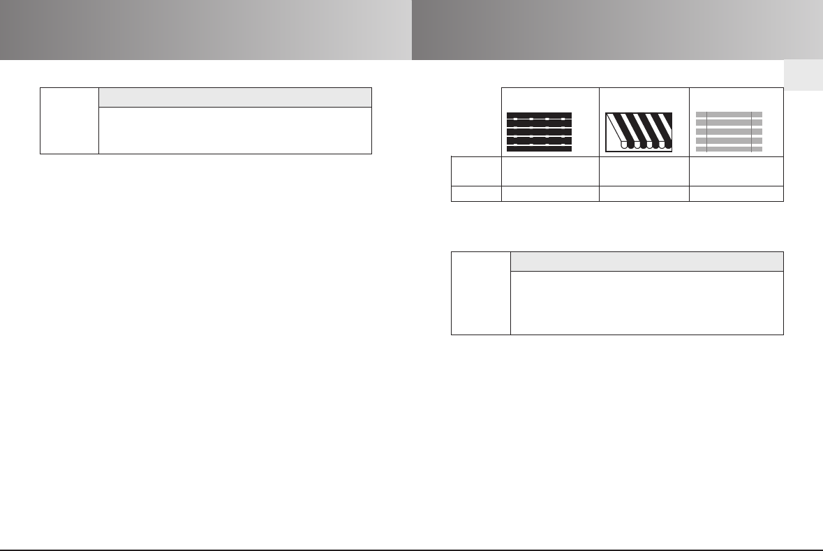
Roller shutters Awning Venetian blind
Pos BIntermediate Intermediate Intermediate
position position position
Pos VVentilation position – Tilting position
PREREQUISITE!
The transmitter/transmitter channel has been
programmed.
The end positions of the drive have been set.
The blind/shutter is at its upper end position.
!
EN-16
EN
EN-15
Intermediate positions for roller shut-
ters/ awnings/venetian blinds Delete positions
Delete intermediate position
1. Press the STOP button and also the DOWN button.
2. Hold down this button combination for approx. 3 sec.
The status LED lights up briefly.
Delete ventilation/tilting position
1. Press the STOP button and also the UP button.
2. Hold down this button combination for approx. 3 sec.
The status LED lights up briefly.
Program ventilation/tilting position
1. Move the blind as far as necessary in the UP direction until the
ventilation gaps open or the slats are inverted.
Hold down the UP button until the desired position is reached.
2. In addition press the STOP button.
The blind/shutter will stop. The status LED lights up briefly.
The intermediate position/ventilation position is now
programmed.
PREREQUISITE!
The transmitter/transmitter channel has been
programmed.
The end positions of the drive have been set.
The blind/shutter is at its lower end position.
!
PREREQUISITE!
The transmitter/transmitter channel has been
programmed.
!
Approach intermediate position
1.
Press the DOWN button briefly twice. The status LED lights up
briefly.
2.
The blind travels to the stored intermediate position.
In the case of venetian blinds, after reaching the intermediate
position, the slats turn automatically.
If no intermediate position has been programmed the
blind/shutter travels to the lower end position.
PREREQUISITE!
The transmitter/transmitter channel has been
programmed.
!
Approach ventilation/tilting position
1.
Press the UP button briefly twice. The status LED lights up briefly.
2.
The blind/shutter travels to the stored ventilation/tilting position.
If no ventilation/tilting position has been programmed the
blind/shutter travels to the upper end position.
EN-17 EN-18
EN
Delete transmitter/technical data Battery changing/cleaning/disposal
Delete transmitter/channel
1. Press the STOP button and also the programming button P
(back of unit).
2. Hold down this button combination for approx. 6 seconds until
the status LED lights up briefly orange and then red.
In the unidirectional radio operation the status LED lights up
green briefly twice and then orange during the 6 seconds.
Deletion of all transmitters
1. Press the STOP button and also:
• Programming button P(on back of device)
• UP button
• DOWN button
2. Hold down this button combination for approx. 6 sec.
The status LED lights up briefly twice.
In the unidirectional radio operation the status LED lights up
green briefly twice and then orange during the 6 seconds.
Technical data
Operating voltage 3 V DC
Battery type 2 x LR 06 (AA cells)
Protection class IP 20
Permitted ambient temperature 0 to +50 °C
Radio frequency 915 MHz frequency band
Dimensions in mm L 120 x W 51 x H 26
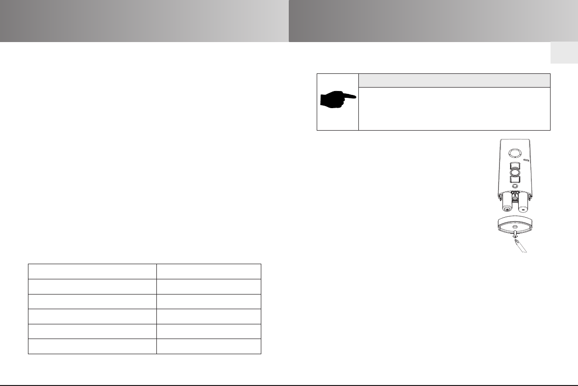
Battery replacement
NOTICE!
• Replace batteries only with identical type
(2 x LR 06; AA cells).
• Dispose of used batteries properly
(collection point).
1. Unscrew the hand-held transmitter using
a suitable screwdriver on the underside of
the device and remove the cover.
2. Remove the batteries.
3. Insert the new batteries (2 x LR 06; AA cells)
correctly in the transmitter.
4. Place the cover on the housing again and screw
on tightly with the screwdriver.
Cleaning
Clean the device with a damp cloth.
Don’t use any cleaning agents. This may attack the plastic.
Disposal
Please observe the current national regulations. Dispose of
according to the condition and existing regulations.
e.g. as:
• Electrical scrap (PCB)
• Plastic (Housing parts)
• Batteries
EN-20
EN
EN-19
Notes on Troubleshooting/Notes on Repair EC-Declaration of conformity
Notes on repair
Please contact us if you are unable to eliminate a problem.
When contacting our service team, please always state the item
description and number from the type plate (back of device).
– Item number – Accompanying conditions
– Item description – Own presumption
– Type of fault – Previously occurring unusual
events
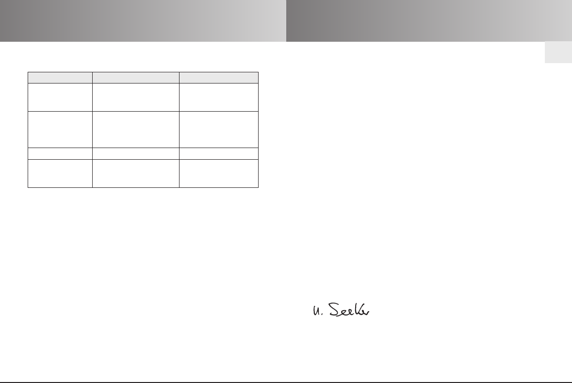
Notes on troubleshooting
Fault Cause Remedy
The drive does not 1. Batteries are low. 1. Replace batteries.
run, the status LED 2. Batteries are incorrectly 2. Insert batteries
does not light up. installed. correctly.
The drive does 1. The receiver is outside 1. Reduce distance to
not run, the status the radio range. the receiver.
LED lights up red. 2. Receiver out of 2. Switch on or
order or faulty. exchange receiver.
Drive does not run. Wrong group selected. Select the right group.
Drive operates in Directions are Delete transmitter
the wrong incorrectly allocated. and reprogram.
direction.
E C - D E C L A R A T I O N O F C O N F O R M I T Y
We hereby declare that the following mentioned product/s meet/s
the standards of the European Community.
Product name: ProLine 2-915
xMonoTel 2 (-915) all versions (Progreso1)
xLumeroTel 2 (-915) all versions (Progreso1M)
xVarioTel 2 (-915) all versions (Progreso5M
xTempoTel 2 (-915) all versions
Description: Radio hand-held transmitters for bidirectional
communication between transmitters and
receivers to control roller shutters, awnings and
venetian blinds
The conformity of the indicated product(s) with the most important
safety requirements is verified by the conformation to the
following guidelines and standards:
xEMC Directive 2004/108/EC
xRoHS Directive 2002/95/EC
xR&TTE-Directives 1999/5/EC
xETSI EN 301489-1/-3
xETSI EN 300220-3
Beuren, 29.12.2009
elero GmbH
Ulrich Seeker Antriebstechnik
– CE Officer – Linsenhofer Str. 59–63
– Representative – D-72660 Beuren
Please visit us on the Internet if you require a contact outside
Germany.