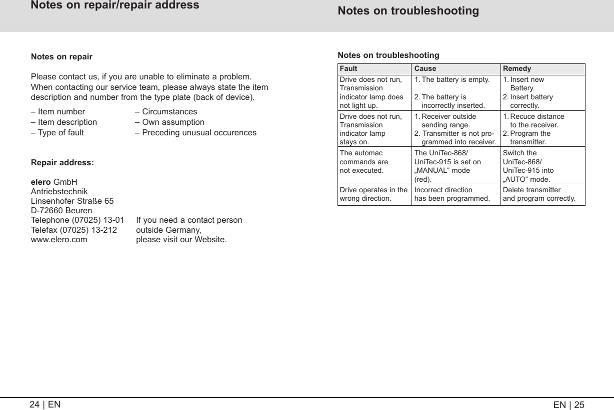
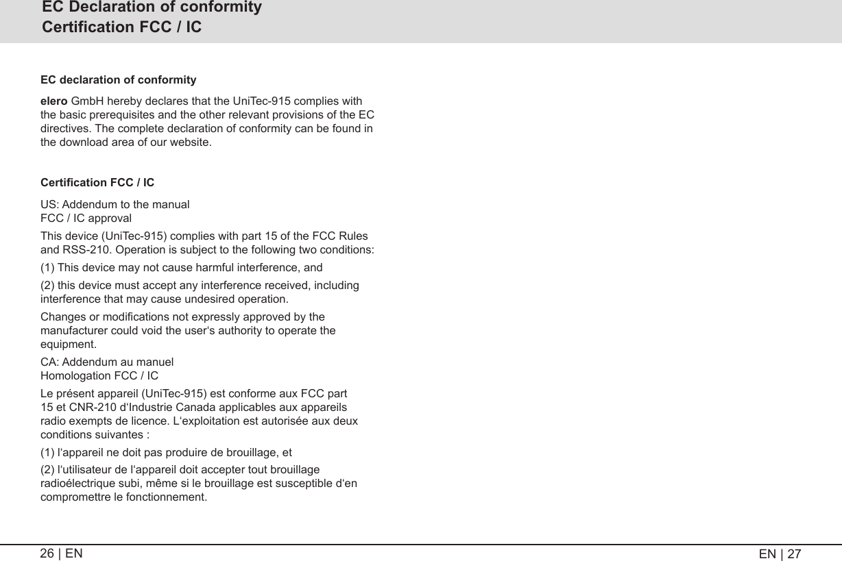
elero Antriebstechnik 2833009X Low power transceiver for screen market User Manual UniTec 868 915 BA 181006706 EN 0715 indd

elero GmbH Antriebstechnik Low power transceiver for screen market UniTec 868 915 BA 181006706 EN 0715 indd

User Manual

181006706_EN_0715Operating instructions (translation)Please take care of the operating instructions!ENUniTec-868, UniTec-915  Nr. 28 330 0006, Nr. 28 330 0906
Device explanation ......................................................................3Safety instructions ......................................................................4Safety instructions/Exclusion of liability  .................................4Scope of supply/General information .......................................6Intended use ................................................................................6Safety instructions for radio operation ..................................... 7Mounting of the wall bracket ......................................................8Explanation of functions ............................................................9  Bidirectional radio system  ......................................................9  Unidirectional radio system  .................................................... 9  Initial operation  .......................................................................9 Note  .....................................................................................10  Status display of the indicator lamp  ..................................... 10  Group control  .......................................................................12  Selection button Auto/Manual  ..............................................12  End position/intermediate position ........................................13 Ventilation/tilting  ...................................................................13Programming a transmitter/channel  ......................................14  Programming additional transmitters/channels  .................... 15  Group mode  .........................................................................16Intermediate positions for roller shutters/awnings/ venetian blinds ..........................................................................17  Programming the intermediate position ................................17  Programming the ventilation/tilting position ..........................17  Approaching the intermediate position .................................18  Approaching the ventilation position/tilting ............................ 18  Deleting the intermediate position ........................................19  Deleting the ventilation slots/tilting ........................................ 19  Approaching the end positions  ............................................20Deleting a transmitter/channel ................................................. 21  Deleting all transmitters  .......................................................21Technical data ............................................................................ 21Replacing the battery ................................................................ 22Cleaning .....................................................................................22Disposal......................................................................................22Notes on repair/repair address ................................................23Notes on troubleshooting .........................................................24Manufacturer’s declaration ......................................................25Contents2 | EN Warning adviceContentsEN | 3
Warning adviceEN | 5K0HPR7HF5HVHWZHHN 3RV 3RVZHHNK 3RV5HVHW3RV 3267DVWH3267DVWHK7DVWHZHHN7DVWH5HVHW7DVWHUniTec-868KontrollleuchteHand-/Automatik-PProgramming buttons P  (all-purpose) Device explanation4 | EN Safety instructions / Exclusion of liabilityExclusion of liability:It is essential to observe these operating instructions, if the UniTec-868 /UniTec-915 is to be used safely and if the vari-ous product characteristics and performance features are to be achieved. elero GmbH assumes no liability for personal injuries, property damages and financial losses that arise from non-observance of the operating instructions. Liability for material defects is excluded in such cases. STOP!   Observance of the operating instructions is the  prerequisite for disturbance-free operation and  entitlement for claims related to defects.  •   Therefore, first read the operating instructions before you use the device!  •   Ensure that the operating instructions are available to the user in legible form.  •   The operator must ensure that the basic safety measures are observed and fulfilled.  •   The operator must have completely read and understood the operating instructions.Safety instructions: Buttons under the cover flapManual/  automatic  sliding switch Alarm signal  control light CoverUP button STOP button DOWN button
EN | 76 | EN Warning adviceGeneral safety instructions CAUTION!  Observe the following safety instructions!   Failure to observe them can lead to bodily injuries! General  •   Never install or use damaged products.  •   Only use unmodified original elero electrical parts.  •   If the device is opened without permission or used in an improper manner, or if it is incorrectly installed or operated, there is a risk of damage to persons and property.  •   The device contains small parts which can be swal-lowed. Installation  •   All installation work must be carried out by an  electrician.  •   This electrician must be suitably qualified.  •   Observe any country-specific conditions when  installing the device.  •   The device may only be used by persons who have read and understood the operating instructions. Operation  •   Only use in dry rooms (please observe the stated  protection  class).   •   If one or more transmitters are used for controlling the system, its operating range must stay visible during operation. •   Replace the battery only with batteries of the identical type (CR 2032). •   Keep children away from the control units. Scope of supply / General information / Intended useScope of supply UniTec-868 / UniTec-915 operating unit  (batteries included in the device)Wall bracket2 wall plugs (Ø 6 mm)2 screws (4 x 35) Operating instructionsGeneral information You can control one or more receivers with the UniTec-868 /UniTec-915 transmitter.The UniTec-868 / UniTec-915 can be operated manually at any time.This device is characterised by simple operation and large control buttons.Intended useThe UniTec-868 / UniTec-915 is a single-channel transmitter. It can be used unidirectionally (compatible with the existing ProLine pro-gram) or bidirectionally. The handheld transmitter must only be used for controlling roller shutters, venetian blinds and sun protection sys-tems which are fitted with elero radio receivers. Other uses or use going beyond this is considered to be contrary to the intended use.elero GmbH shall not be liable for damages in case of:  •   Other use than described above   •   Changes to the device  •  Improper usePlease see the technical data contained in these operating  instructions.Third-party devices should only be connected after consultation with your specialised dealer.
EN | 98 | EN Warning adviceInstructions for radio operation CAUTION!  Observe the following safety instructions for radio operation!   Only use radio systems, if they are allowed and can be operated without interference.  •   Please note that radio systems must not be oper-ated in areas with an increased risk of interference (e. g. hospitals, airports, ...).  •   The remote control is permitted only for devices and equipment for which a malfunction of the transmitter or receiver does not give rise to a hazard to persons, animals or objects or where this safety risk is covered by other safety equipment.  •   The operator has no protection whatsoever against interference by other telecommunication installations and local terminals (e. g. also from radio installations which are operated properly in the same frequency range).  •   The range of the radio signal is limited by the govern-ment and the built environment.Safety instructions for radio operation Mounting of the wall bracket1.  Attach the bracket to the wall, with the two wall plugs and screws which are provided.2. Slide  the UniTec-868 / UniTec-915 from the top onto the wall bracket. NOTE!   Before installation in the required assembly position, check that the transmitter and receiver are function-ing properly.   The bracket has to be fixed so that the drill hole does not touch any electrical lines.Mounting of the wall bracket
Warning adviceEN | 1110 | EN Note Do not press the P button until the receivers are in programming mode. The active channel decides for a radio system during programming. If the receivers are not in programming mode, the transmitter channel changes to unidirectional mode. Press the STOP and P buttons simultaneously for 6 seconds until the status display lights up, to restore the initial condition. Status display of the indicator lamp A radio signal is displayed by the illumination of the status display (LED indicator lamp). After the status display, the operating mode of the transmitter is displayed by the same indicator lamp. Explanation of functions Bidirectional radio system A bidirectional radio system transmits radio signals to radio receiv-ers and enables feedback to the transmitter. The radio signal can be sent directly to the target receiver. If this is not possible, then the radio signal is forwarded via other bidirectional participants until the signal reaches the target receiver. The target receiver carries out the command and sends a confirmation back to the transmitter. Bidirectional radio operation is only possible, if all participants are bidirectional. Otherwise, the system is only unidi-rectional. Unidirectional radio system A unidirectional radio system transmits radio signals to radio receivers. However, unlike in a bidirectional radio system, the radio receivers cannot send back any feedback to the transmitter. A passing-on of the radio signals from one radio receiver to the next radio receiver is not possible. Initial operation The handheld transmitter is switched on by pressing the button, and status display and operating mode are displayed successively by the indicator lamp. The handheld transmitter is in automatic mode during initial operation. As long as no receiver is pro-grammed, the automatic display is not available. Explanation of functionsExplanation of functionsMeaning of the various colours of status and operating mode  display:  Status  displayOper-ating mode display  Meaning ashing  orange without  Transmitter is not programmed quick ashing orange without  Programming mode group larger than 10 drives Programming is pos-sible only in the same channel.  Please nd further information at the end of the section  „Programming additional transmit-ters/channels“ of these instructions.
Explanation of functions12 | EN Explanation of functionsEN | 13 Status  displayOper-ating mode display  Meaning orange  green  Transmitter functions bidirectionally, Operating mode Automatic orange  red  Transmitter functions bidirectionally, Operating mode Manual green  green  Transmitter functions unidirection-ally, Operating mode Automatic green  red  Transmitter functions unidirection-ally, Operating mode Manual 3 x orange  /red green  Transmitter functions bidirectionally, Operating mode Automatic, Transmitter deleted3 x orange  /redred Transmitter functions bidirectionally, Operating mode Manual, Transmitter deleted3 x green  /red green Transmitter functions unidirectionally, Operating mode Automatic, Transmitter deleted3 x green  /red red Transmitter functions unidirectionally, Operating mode Manual, Transmitter deletedThe transmitting power or radio range will be reduced by the reduction in the performance of the battery. No more functions are executed and there is no display, if the voltage drops below 2 Volt. Group controlA group is understood to mean the control of several receivers at the same time. The selected group is controlled by a travel command. Any number of receivers can be programmed and con-trolled in the channel. The UniTec-868 / UniTec-915 can be programmed into several receivers.  Selection button Auto/Manual An already programmed transmitter (uni- or bidirectional) can be switched between automatic and manual operation by using the selection button. The current mode of the handheld transmitter channel is queried by briefly pressing the selection button. Pressing and holding (for approx. 1 second) the selection but-ton switches the automatic mode off. After the transmit signal, the operating mode display lights up red. The receivers now only carry out manual travel commands and do not respond to auto-matic travel commands. Pressing and holding (for approx. 1 second) the selection button again, switches the automatic mode back on. After the transmit signal, the operating mode display lights up green. The receivers now execute automatic and manual travel commands.
Note When switching on the automatic, an upward travel of the receiver is triggered (provided that sensors are programmed in the  receiver). End positionThe end position is the point where the roller shutter/venetian blind is in the upper or lower position. In this position, the sun protection system is completely extended or retracted. Intermediate position The intermediate position is a freely-selectable position of the shutter/blind between the top and bottom end position. This can be approached from the top end position after programming is complete.For this, press the Down button briefly twice successively.In venetian blind mode, any programmed tilting is carried out auto-matically following the intermediate position.Ventilation/TiltingThe ventilation/tilting position is a freely selectable position of the shutter/blind between the top and bottom end position. Using this function, you can raise the roller shutter from the lower end posi-tion until the ventilation gaps are again open. With venetian blinds, the slats are inverted.For this, press thee UP button briefly twice successively.Explanation of functions14 | EN  EN | 15Programming a transmitter / channel Programming a transmitter/channel  PREREQUISITE!   The receiver must be installed.!1.  Disconnect the fuse - and reconnect after a few seconds.   The receiver is now in programming mode for about 5 minutes.2.  Stand with the UniTec-868 / UniTec-915 in front of the shutter/blind.3.  Briefly press the programming button P.   The shutter/blind will automatically move up and down (for approx. 2 minutes). 4.  To define the keyboard layout, press the UP button on the UniTec-868 / UniTec-915 (for max. 1 second) immediately after the start of the upward travel.   The shutter/blind will stop for a short time. 5.  Press the DOWN button on the UniTec-868/UniTec-915 (for max. 1 second) immediately after the start of the downward travel.  The shutter/blind stops.  The UniTec-868 / UniTec-915 is now programmed. UniTec-868KontrollleuchteHand-/Automatik-PProgramming buttons P  (all-purpose)
Warning adviceEN | 17Programming additional transmitters/channels Programming additional transmitters/channels NOTE!   If several receivers are connected to the same feed line, then all are simultaneously in programming mode. The shutters/blinds start a brief “random” up/down travel. The longer you wait with the program-ming, the greater will be the offset.   Individual transmitters/channels can now be assigned to the respective receiver.   You can stop the brief up/down travel by briefly pressing the STOP button on a transmitter which has already been programmed.   The channel assignment/change can now be made without having to disconnect the individual receivers.   If the shutter/blind travels in the wrong direction, delete the transmitter and reprogram it. (→ see Deleting a transmitter) Programming additional transmitters/chanels Programming additional transmittersTo programme additional transmitters in one receiver, please pro-ceed as follows:1.   Press  the  UP-, DOWN- and the programming button P simulta-neously (for 3 seconds). The status LED lights up briefly.    Push the programming button P on the new transmitter to be programmed until the status LED lights up briefly. 2.   Press  the  UP button immediately after the start of upward travel (max. 1 second).   The status LED lights up briefly. The shutter/blind stops – starts moving again – stops and then moves in the DOWN direction. 3.   Press  the  Down button immediately after the start of down-ward travel (max. 1 second).   The status LED lights up briefly. The shutter/blind stops.The transmitter or the transmitter channel has been programmed.Group mode If more than 10 bidirectional receivers are being programmed at the same time, the transmitter channel in programming mode switches to group mode. The group mode is indicated by fast flashing with pauses. Programming in group mode ends after a 2-minute pause or pressing the STOP button for 6 seconds. 16 | EN
18 | EN Warning adviceEN | 19Intermediate positions for roller shutter/awning/venetian blind    Roller shutter  Awning  Venetian blind Pos ▼ Intermediate position  Intermediate position  Intermediate position Pos ▲ Ventilation position  Fabric tightening  Tilting position1.  Travel the shutter/blind to the desired position with the DOWN button.  Keep  the  DOWN button pressed until the desired position has been reached.2.   Press  the  STOP button in addition.   The shutter/blind stops.  The intermediate position is now programmed.Programming Pos ▲ (ventilation/tilting position, fabric tightening) PREREQUISITE!  The transmitter is programmed.  The end positions of the drive have been set.  The blind is at its lower end position.!Programming Pos ▼ (intermediate position) PREREQUISITE!  The transmitter is programmed.  The end positions of the drive have been set.  The shutter/blind is in its upper end position.!1.  Travel the shutter/blind with the transmitter as far as necessary in the UP direction until the ventilation slots open or the tilting is reached.  Hold down the UP button until the desired position is reached..Intermediate positions for roller shutter/awning/venetian blind2.   Press  the  STOP button in addition.   The shutter/blind stops.   You have programmed the position ventilation slots/tilting/fabric tightening.1. Press the DOWN button briefly twice successively.2. The drive travels to the stored intermediate position.    If no intermediate position has been programmed, the shutter/blind travels to the lower end position. PREREQUISITE!  The transmitter is programmed.  The intermediate position is programmed.!Approaching Pos ▼ (intermediate position)1. Press the UP button briefly twice successively.2.  The shutter/blind travels to the stored ventilation position/fabric tightening.    If no ventilation/tilting position has been programmed, the shut-ter/blind travels to the upper end position. PREREQUISITE!  The transmitter is programmed.   The ventilation position/fabric tightening is programmed.!Approaching Pos ▲ (ventilation position/fabric tightening)
20 | EN Intermediate positions for roller shutter / awning / venetian blind  PREREQUISITE!   The transmitter is programmed.!Deleting Pos ▼ (intermediate position)1.   Press  simultaneously:  •      DOWN button  •      STOP button2. Hold down this button combination for approx. 3 seconds.    The status LED lights up briefly. Deleting Pos ▲ (ventilation/tilting position, fabric tightening) 1.   Press  simultaneously: •      UP button  •      STOP button2.  Hold down this button combination for approx. 3 seconds.  The status LED lights up briefly. Approaching the lower end position (roller shutter/awning) Press the DOWN button briefly. The shutter/blind approaches the lower end position/the awning moves out. Approaching the lower end position (venetian blind) Press the DOWN button until the status LED lights up briefly. The blind approaches the lower end position. If you press the DOWN button only briefly (jogging mode), the blind moves a short distance and stops again. Approaching the upper end position (roller shutter/awning) Press the UP button briefly. The shutter/blind approaches the upper end position/the awning retracts. Approaching the upper end position (venetian blind) Press the UP button until the status LED lights up briefly. The blind approaches the upper end position. If you press the UP button only briefly (jogging mode), the blind moves a short distance and stops again.  PREREQUISITE!   The transmitter/transmitter channel is programmed.  The end positions of the drive have been set. !Approaching the end positions roller shutter / awning / venetian blind EN | 21
22 | EN Replacing the battery  NOTE!   •  Replace batteries only with the identical type (1 x CR 2032).  •  Dispose of used batteries properly (collection point).Replacing the battery1. Slide the wall transmitter upwards     from the wall bracket.2. Remove the battery.3.  Insert a new battery     correctly.CR2032CleaningClean the device with a damp cloth only. Do not use cleaning agents, these can attack the plastic.DisposalPlease observe the current national regulations. Dispose of according to the condition and existing regulations.e.g. as: • Electronic waste (PCB)• Plastic (housing parts)• BatteriesChanging the batteries/ cleaning / disposal Warning adviceEN | 23Deleting a transmitter / Technical data   Operating voltage  3 V DC   Battery CR 2032   Protection class  IP20   Permitted ambient temperature   0 °C to +50 °C   Radio frequency  868 MHz band or      915 MHz band Technical dataDeleting all transmitters 1. Press the STOP button and also:   • Programming button P (below the cover)  • UP button • DOWN button2.  Hold down this button combination for approx. 6 seconds until the status LED briefly lights up orange and then red.    In unidirectional operation, the status LED briefly lights up green twice and then red, within these 6 seconds. Deleting a transmitter/channel 1.  Press  the  STOP button and also the programming button P (below the cover). 2.  Hold down this button combination for approx. 6 seconds until the status LED briefly lights up orange and then red.  In unidirectional operation, the status LED briefly lights up green twice and then red, within these 6 seconds.
24 | EN Notes on troubleshooting Fault  Cause  Remedy Drive does not run,  1. The battery is empty.  1. Insert new Transmission       Battery. indicator lamp does  2. The battery is  2. Insert battery not light up.    incorrectly inserted.    correctly. Drive does not run,  1. Receiver outside  1. Recuce distance Transmission    sending range.    to the receiver. indicator lamp  2. Transmitter is not pro-  2. Program the  stays on.    grammed into receiver.    transmitter. The automac  The UniTec-868/   Switch the   commands are   UniTec-915 is set on   UniTec-868/   not executed.   „MANUAL“ mode  UniTec-915 into     (red).   „AUTO“ mode.  Drive operates in the  Incorrect direction  Delete transmitter wrong direction.  has been programmed.  and program correctly.Notes on troubleshootingWarning adviceEN | 25Notes on repair/repair addressNotes on repairPlease contact us, if you are unable to eliminate a problem.When contacting our service team, please always state the item description and number from the type plate (back of device).– Item number  – Circumstances– Item description  – Own assumption– Type of fault  –  Preceding unusual occurencesRepair address:elero GmbHAntriebstechnikLinsenhofer Straße 65D-72660 BeurenTelephone (07025) 13-01  If you need a contact personTelefax (07025) 13-212  outside Germany,www.elero.com  please visit our Website.
26 | EN Warning adviceEN | 27EC declaration of conformity elero GmbH hereby declares that the UniTec-915 complies with the basic prerequisites and the other relevant provisions of the EC directives. The complete declaration of conformity can be found in the download area of our website. Certication FCC / IC US: Addendum to the manual  FCC / IC approval This device (UniTec-915) complies with part 15 of the FCC Rules and RSS-210. Operation is subject to the following two conditions: (1) This device may not cause harmful interference, and (2) this device must accept any interference received, including interference that may cause undesired operation. Changes or modications not expressly approved by the manufacturer could void the user‘s authority to operate the equipment. CA: Addendum au manuel  Homologation FCC / IC Le présent appareil (UniTec-915) est conforme aux FCC part 15 et CNR-210 d‘Industrie Canada applicables aux appareils radio exempts de licence. L‘exploitation est autorisée aux deux conditions suivantes : (1) l‘appareil ne doit pas produire de brouillage, et (2) l‘utilisateur de l‘appareil doit accepter tout brouillage radioélectrique subi, même si le brouillage est susceptible d‘en compromettre le fonctionnement. EC Declaration of conformity Certification FCC / IC
309312 02We reserve the right to make technical changes.elero GmbH Antriebstechnik Linsenhofer Str. 65 D-72660 Beuren Fon: +49 7025 13-01 Fax: +49 7025 13-212 info@elero.de www.elero.com

Navigation menu