etatronix EXM10RXLINK Wireless Power Receiver User Manual exm10Rx Integration Manual Draft 01
etatronix GmbH Wireless Power Receiver exm10Rx Integration Manual Draft 01
Contents
- 1. Users Manual
- 2. Integration manual
Integration manual
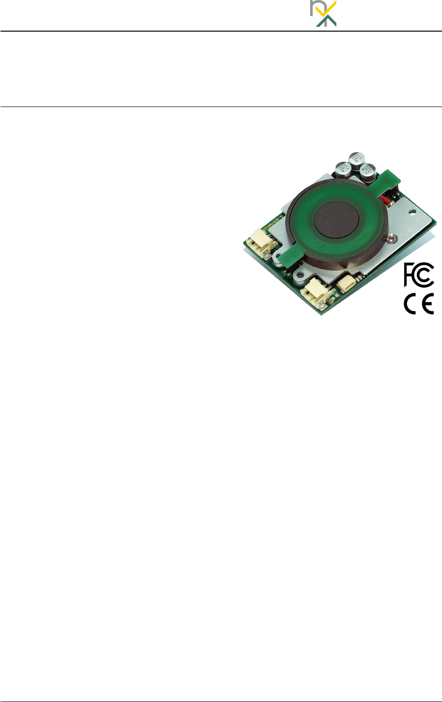
exm10Rx
Integration Manual etatronix
exm10Rx
Integration Manual
Introduction
The exm module series provides easy to
use plug and play solutions for high per-
formance wireless power transmission
between a power transmitter (Tx) and a
power receiver (Rx). In combination with
a proprietary data transmission channel,
the series provides a fast regulation loop
and the ability to transfer customer data
in parallel. Compliance to global safety
and EMC standards qualifies the series
for worldwide markets.
The exm10 series contains easy to use
power receiver modules that can be
wirelessly powered with any etatronix
exm10 power receiver. They provide up
to
10 W
at the DC output. A LiIon charge
function as well as a battery manage-
ment system including a state of charge
algorithm is available.
In combination with an exm10 power
transmitter, the system complies to CE
and FCC regulations. It has a modular
approval which minimizes the certifica-
tion effort of the application containing
the module.
exm10Rx-Integration Manual-Draft-01.pdf
© etatronix GmbH, August 2018 1/ 10

etatronix exm10Rx
Integration Manual
Table of Contents
1 Electrical Specification 3
1.1 OperatingConditions .............................. 3
1.2 Interface ...................................... 3
1.3 Compliance .................................... 3
2 Mechanical Specification 4
2.1 Dimensions .................................... 4
2.2 Mounting...................................... 5
3Interfaces 6
3.1 PowerConnector................................. 6
3.2 BatteryConnector ................................ 6
3.3 SignalConnector ................................. 7
4 Functional Description 8
5 Compliance 9
References 10
Revision History
Revision Date Changes
Draft-01 8/2018 First draft released
2/ 10 exm10Rx-Integration Manual-Draft-01.pdf
© etatronix GmbH, August 2018

exm10Rx
Integration Manual etatronix
1 Electrical Specification
1.1 Operating Conditions
Parameter Min Typ Max Unit
Output voltage1,3 - - 20 V
Output current1,2 - - 2.7 A
Ambient temperature -25 - 70 ◦C
Standby current 3- tbd. - mA
Data transmission frequency - 2 - MHz
1
In case of a connected battery, output current and voltage depend on actual charge state. The module
works in CC/CV mode.
2Output current and voltage limitation can be tailored to specific load and battery requirements.
3Receiver module not connected with power transmitter, BMS active.
1.2 Interface
Parameter Min Typ Max Unit
Low level digital interface 1-0.1 - 0.6 V
High level digital interface 12.7 - 3.4 V
Maximum voltage at PG 1,2 - - 4.2 V
Maximum current PG 1- - 10 mA
Output Capacity - - 440 µF
Battery Fuse Rating - T7 - A
Battery Fuse Melting Integral - 8.7 - A2Sec
1Internal limiting series resistor: 330 Ω.
2Voltage at PG-pin shall not exceed the output voltage.
1.3 Compliance
Regulation Description
EN 55011 class B EMIregulation for home equipment
exm10Rx-Integration Manual-Draft-01.pdf
© etatronix GmbH, August 2018 3/ 10
etatronix exm10Rx
Integration Manual
2 Mechanical Specification
2.1 Dimensions
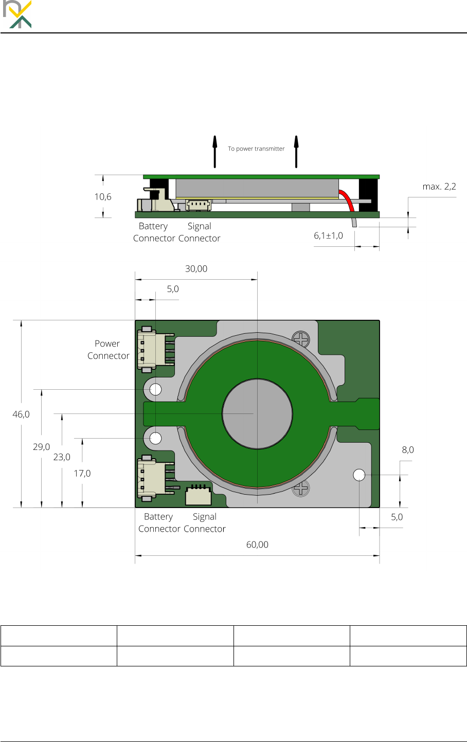
Figure 1: Dimensions
Length Width Height Weight
60.0mm +/-0.2 46.0mm +/-0.2 10.6mm +/-0.21tbd
1Notice that the height varies and will be higher at the solder points.
4/ 10 exm10Rx-Integration Manual-Draft-01.pdf
© etatronix GmbH, August 2018
exm10Rx
Integration Manual etatronix
2.2 Mounting
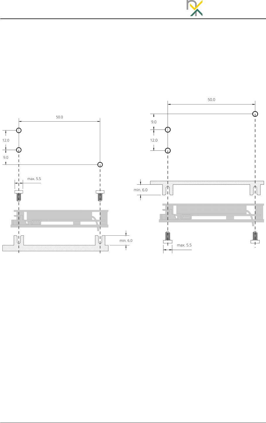
Figure 2shows two possible examples for the mounting of the exm module. Using the
provided holes, the module can be mounted on a separate carrier (a) or on the surface
which faces the power coil (b). In order to fit onto the module, the screw-head should
have a maximum diameter of 5.5mm. The height of the standoffs should be at least
6mm.
(a) Carrier Mounting (b) Surface Mounting
Figure 2: Mounting Examples
exm10Rx-Integration Manual-Draft-01.pdf
© etatronix GmbH, August 2018 5/ 10
etatronix exm10Rx
Integration Manual
3Interfaces
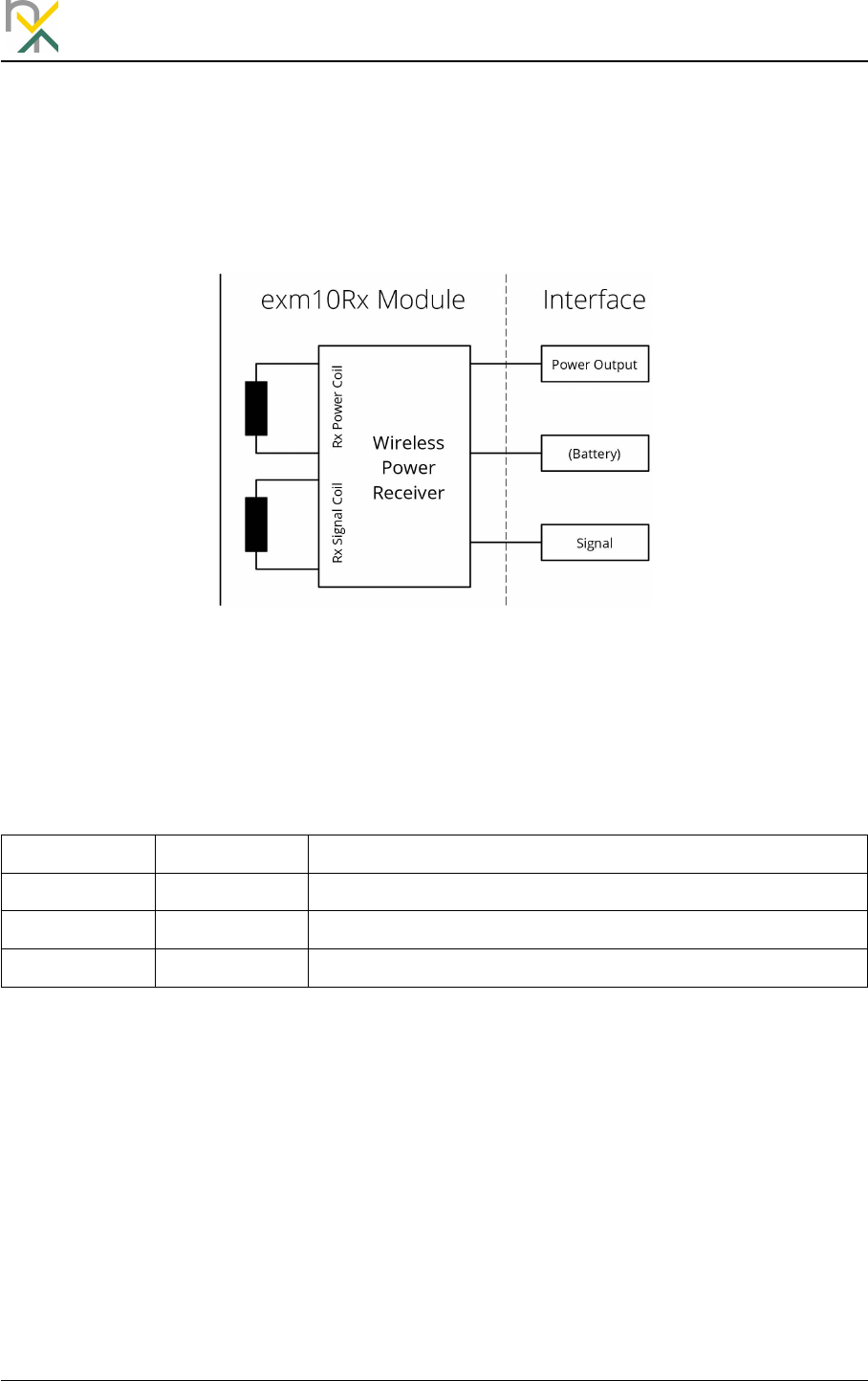
The interface of the exm module consists of a power output to connect the load, a
signal output for communication with the module or via the wireless link and a separate
battery connector.
Figure 3: Interfaces
3.1 Power Connector
Type: TE Connectivity 1-292173-3
Pin Name Function
1 Vout- Output GND
2 PG Power Good1
3 Vout+ Output Voltage
1Open collector to GND
3.2 Battery Connector
Type: TE Connectivity 1-292173-3
6/ 10 exm10Rx-Integration Manual-Draft-01.pdf
© etatronix GmbH, August 2018

exm10Rx
Integration Manual etatronix
Pin Name Function
1 GND Battery -
2 NTC Thermistor of the battery to GND1
3 Vbat+ Battery +2
1Open collector to GND
2Protected by an internal Fuse
3.3 Signal Connector
Connection to the signal connector is not necessary for power transmission but can
be used for status updated and customer-specific data transmission. More details are
specified in [1].
Type: JST SM04B-SRSS-TB
Pin Name Function
1 VCCint Internal Supply Voltage
2 COM1 I2C SDA, UART Tx1
3 COM2 I2C SCL, UART Rx1
4 GNDint Internal GND
1Depending on configuration
exm10Rx-Integration Manual-Draft-01.pdf
© etatronix GmbH, August 2018 7/ 10
etatronix exm10Rx
Integration Manual
4 Functional Description
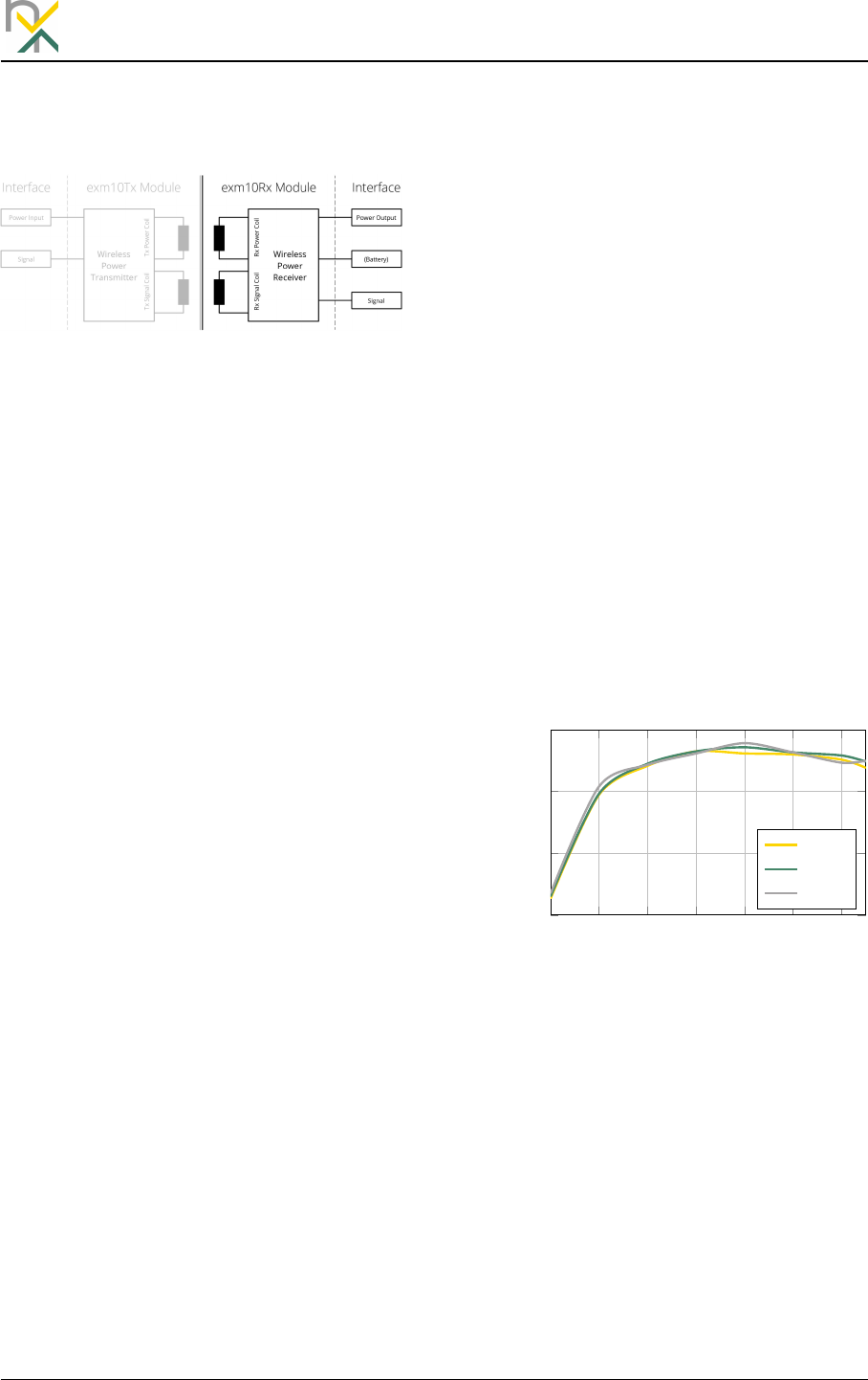
Figure 4: Block Diagram
To maximize the power transmission
efficiency, the power transmission be-
tween transmitter and receiver modules
of the exm10 series is realized using res-
onant circuits. These resonant circuits
additionally provide the ability to vary
the transmitted power by changing the
switching frequency. By increasing the
switching frequency, the available power
in the receiver side decreases.
For the accurate output voltage regula-
tion, a control loop is necessary. The out-
put conditions like output current, volt-
age and power are measured on the re-
ceiver side and sent to the power trans-
mitter. If corrections are necessary, the
transmitter will change the switching fre-
quency to the desired value.
An appropriate control loop needs a
fast signal transmission with little de-
lay. Often it’s advantageous to trans-
fer status or customer-specific informa-
tion between both units. To meet these
two demands, the exm10 series pro-
vides a data channel that allows the
parallel transmission of analog regula-
tion information as well as digital status
and customer-specific information. This
transmission is done using a second pair
of coupled coils. Like the power trans-
mission coils, the signal coils are form-
ing a near field coupling system thus the
intended use of radio waves isn’t neces-
sary.
The efficiency of the whole power trans-
mission system (input connector to
battery connector) depends on the
setup such as distance, lateral displace-
ment and output power. Figure 5de-
picted the efficiency with a varying dis-
tance, measured with exm10Rx4V2C
and exm10Tx24.
2 4 6 8 10 12 14
68%
74%
80%
86%
PowerW
Efficiency
3mm
5mm
6mm
Figure 5: Efficiency over distance
8/ 10 exm10Rx-Integration Manual-Draft-01.pdf
© etatronix GmbH, August 2018

exm10Rx
Integration Manual etatronix
5 Compliance
The integrator must ensure that the FCC label is clearly visible outside of the OEM
enclosure. The label has to contain the FCC-ID as well as the following statement:
This device complies with Part 15 of the FCC Rules [and with Industry Canada licence-
exempt RSS standard(s)]. Operation is subject to the following two conditions:
1. this device may not cause harmful interference, and
2.
this device must accept any interference received, including interference that
may cause undesired operation.
FCC ID for exm10Rx serie: 2AOR8EXM10RXLINK
exm10Rx-Integration Manual-Draft-01.pdf
© etatronix GmbH, August 2018 9/ 10
