Grizzly G05281 G0528 Manual User E4ea664f Bb76 1d54 E93b 53381a2b5739
User Manual: grizzly g05281 Grizzly Router G0528 User Guide |
Open the PDF directly: View PDF ![]() .
.
Page Count: 32

COPYRIGHT © SEPTEMBER, 2003 BY GRIZZLY INDUSTRIAL, INC.
WARNING: NO PORTION OF THIS MANUAL MAY BE REPRODUCED IN ANY SHAPE
OR FORM WITHOUT THE WRITTEN APPROVAL OF GRIZZLY INDUSTRIAL, INC.
#TR5457 REVISED MAY, 2004. PRINTED IN TAIWAN
ROUTER TABLE
MODEL G0528
INSTRUCTION MANUAL

WARNING
Some dust created by power sanding, sawing, grind-
ing, drilling, and other construction activities contains
chemicals known to the State of California to cause
cancer, birth defects or other reproductive harm. Some
examples of these chemicals are:
• Lead from lead-based paints.
• Crystalline silica from bricks, cement, and
other masonry products.
• Arsenic and chromium from chemically treated
lumber.
Your risk from these exposures varies, depending on
how often you do this type of work. To reduce your
exposure to these chemicals: work in a well ventilated
area, and work with approved safety equipment, such
as those dust masks that are specially designed to fil-
ter out microscopic particles.
Table of Contents
SECTION 1: SAFETY ....................................................................................................................... 2
Safety Instructions For Power Tools .......................................................................................... 2
Additional Safety Instructions For Router Tables ....................................................................... 4
SECTION 2: INTRODUCTION ......................................................................................................... 5
Commentary ............................................................................................................................... 5
SECTION 3: CIRCUIT REQUIREMENTS ........................................................................................ 6
General ....................................................................................................................................... 6
Electrical ..................................................................................................................................... 6
SECTION 4: MACHINE FEATURES ................................................................................................ 7
SECTION 5: SET UP ........................................................................................................................ 8
G0528 Inventory ......................................................................................................................... 8
Hardware Recognition Chart ...................................................................................................... 9
Clean Up .................................................................................................................................. 10
Site Considerations .................................................................................................................. 10
Assembly .................................................................................................................................. 11
Rubber Feet ............................................................................................................................. 11
Cross Supports ........................................................................................................................ 12
Stand ........................................................................................................................................ 13
Table Braces ............................................................................................................................ 13
Fence ....................................................................................................................................... 14
Hold-Downs .............................................................................................................................. 14
Miter ......................................................................................................................................... 15
Router To Table ....................................................................................................................... 15
Switch ....................................................................................................................................... 16
Dust Port Hook-Up ................................................................................................................... 17
SECTION 6: OPERATIONS ............................................................................................................ 18
Before Routing ......................................................................................................................... 18
Routing ..................................................................................................................................... 18
SECTION 7: REFERENCE INFO ................................................................................................... 21
G0528 Machine Data Sheet ..................................................................................................... 22
G0528 Parts Breakdown .......................................................................................................... 23
Warranty & Returns .................................................................................................................. 26

-2- G0528 Sliding Router Table
5. KEEP CHILDREN AND VISITORS AWAY.
All children and visitors should be kept at a
safe distance from work area.
6. MAKE WORKSHOP CHILD PROOF with
padlocks, master switches, or by removing
starter keys.
7. NEVER FORCE TOOL. It will do the job
better and safer at the rate for which it was
designed.
8. USE RIGHT TOOL. DO NOT force tool or
attachment to do a job for which it was not
designed.
1. KEEP GUARDS IN PLACE and in working
order.
2. REMOVE ADJUSTING KEYS AND
WRENCHES. Form a habit of checking to
see that keys and adjusting wrenches are
removed from tool before turning on.
3. KEEP WORK AREA CLEAN. Cluttered
areas and benches invite accidents.
4. NEVER USE IN DANGEROUS
ENVIRONMENT. DO NOT use power tools
in damp or wet locations, or where any
flammable or noxious fumes may exist.
Keep work area well lighted.
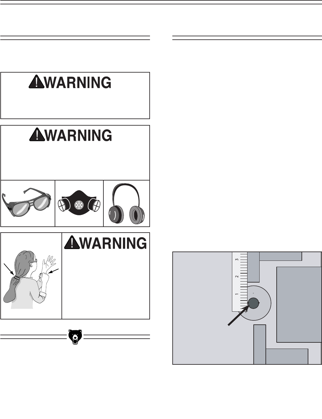
For Your Own Safety Read Instruction
Manual Before Operating This Equipment
Indicates an imminently hazardous situation which, if not avoided,
WILL result in death or serious injury.
Indicates a potentially hazardous situation which, if not avoided,
COULD result in death or serious injury.
Indicates a potentially hazardous situation which, if not avoided,
MAY result in minor or moderate injury. It may also be used to alert
against unsafe practices.
This symbol is used to alert the user to useful information about
proper operation of the equipment.
The purpose of safety symbols is to attract your attention to possible hazardous conditions. This
manual uses a series of symbols and signal words which are intended to convey the level of
importance of the safety messages. The progression of symbols is described below. Remember
that safety messages by themselves do not eliminate danger and are not a substitute for proper
accident prevention measures.
NOTICE
Safety Instructions For Power Tools
SECTION 1: SAFETY

G0528 Sliding Router Table -3-
9. USE PROPER EXTENSION CORD. Make
sure your extension cord is in good condi-
tion. Conductor size should be in accor-
dance with the chart below. The amperage
rating should be listed on the motor or tool
nameplate. An undersized cord will cause
a drop in line voltage resulting in loss of
power and overheating. Your extension
cord must also contain a ground wire and
plug pin. Always repair or replace exten-
sion cords if they become damaged.
Minimum Gauge for Extension Cords
10. WEAR PROPER APPAREL. DO NOT
wear loose clothing, gloves, neckties, rings,
bracelets, or other jewelry which may get
caught in moving parts. Non-slip footwear
is recommended. Wear protective hair cov-
ering to contain long hair.
11. ALWAYS USE SAFETY GLASSES. Also
use face or dust mask if cutting operation
is dusty. Everyday eyeglasses only have
impact resistant lenses, they are NOT safety
glasses.
12. SECURE WORK. Use clamps or a vise to
hold work when practical. It’s safer than using
your hand and frees both hands to operate
tool.
13. DO NOT OVER-REACH. Keep proper
footing and balance at all times.
14. MAINTAIN TOOLS WITH CARE. Keep
tools sharp and clean for best and safest
performance. Follow instructions for lubri-
cating and changing accessories.
15. USE RECOMMENDED ACCESSORIES.
Consult the owner’s manual for recom-
mended accessories. The use of improper
accessories may cause risk of injury.
16. REDUCE THE RISK OF UNINTENTIONAL
STARTING. On machines with magnetic
contact starting switches there is a risk of
starting if the machine is bumped or jarred.
Always disconnect from power source
before adjusting or servicing. Make sure
switch is in OFF position before reconnect-
ing.
17. CHECK DAMAGED PARTS. Before further
use of the tool, a guard or other part that
is damaged should be carefully checked
to determine that it will operate properly
and perform its intended function. Check
for alignment of moving parts, binding of
moving parts, breakage of parts, mounting,
and any other conditions that may affect
its operation. A guard or other part that is
damaged should be properly repaired or
replaced.
18. NEVER LEAVE TOOL RUNNING
UNATTENDED. TURN POWER OFF. DO
NOT leave tool until it comes to a complete
stop.
19. NEVER OPERATE A MACHINE WHEN
TIRED, OR UNDER THE INFLUENCE OF
DRUGS OR ALCOHOL. Full mental alert-
ness is required at all times when running
a machine.
20. NEVER ALLOW UNSUPERVISED OR
UNTRAINED PERSONNEL TO OPERATE
THE MACHINE. Make sure any instruc-
tions you give in regards to machine opera-
tion are approved, correct, safe, and clearly
understood.
21. IF AT ANY TIME YOU ARE EXPERIENC-
ING DIFFICULTIES performing the intend-
ed operation, stop using the machine! Then
contact our service department or ask a
LENGTH
AMP RATING 25ft 50ft 100ft
0-6 16 16 16
7-10 16 16 14
11-12 16 16 14
13-16 14 12 12
17-20 12 12 10
21-30 10 10 No
Safety Instructions For Power Tools

-4- G0528 Sliding Router Table
Unfamiliarity with this manual could result
in serious personal injury. Read and
become familiar with the contents of this
manual, including all the safety warnings.
No list of safety guidelines can be com-
plete. Operating this machinery may
require additional safety precautions spe-
cific to your shop environment. Failure to
use reasonable caution while operating
this machine could result in serious per-
sonal injury.
1. HAND POSITIONING. Never pass your
hands directly over or in front of the cutter.
As one hand approaches cutter, move it in
an arc motion away from the cutter to the
outfeed side and reposition that hand beyond
the cutter.
2. STOCK LENGTH. Do not rout stock shorter
than 12 inches without special fixtures or jigs.
Where practical, rout longer stock and cut to
size.
3. BLIND CUT WHENEVER POSSIBLE. This
keeps the cutters on the underside of the
workpiece and provides a distance guard for
the operator.
4. TEST ROTATION. Always rotate the spindle
by hand, with the machine unplugged, to test
any new setup to ensure proper cutter clear-
ance before starting the machine.
5. KEEP ANY UNUSED PORTION OF THE
CUTTER BELOW THE TABLE SURFACE.
6. DEPTH OF CUT. Never remove too much
material in one pass. Several light passes are
safer and give a cleaner finish.
7. IF AT ANYTIME YOU ARE EXPERIENC-
ING DIFFICULTIES PERFORMING THE
INTENDED OPERATION, STOP USING
THE ROUTER TABLE! Then contact our
service department or ask a qualified expert
how the operation should be performed.
8. SAFETY DEVICES. The use of push sticks
as safety devices in some applications is
smart; in others it can be quite dangerous.
If the push stick comes in contact with the
cutter on the end grain, it can fly out of your
hand like a bullet, potentially causing seri-
ous injury.
We recommend using some type of fixture,
jig, or hold-down device as a safer alterna-
tive. Use a guard or other type of protective
device at all times.
9. ALWAYS FEED AGAINST THE ROTA-
TION OF THE CUTTER.
10. DO NOT REMOVE THE RETRACTABLE
GUARD ON THE FENCE.
11. BE AWARE THAT CERTAIN WOODS
MAY CAUSE AN ALLERGIC REACTION
in people and animals, especially when
exposed to fine dust. Make sure you know
what type of wood dust you will be exposed
to, the possibility of a allergic reaction and
always wear an approved respirator.
12. READ AND UNDERSTAND THE
INSTRUCTION MANUAL SUPPLIED
WITH THE ROUTER TO BE INSTALLED
IN THIS TABLE.
13. DO NOT REACH UNDER THE ROUTER
TABLE WHILE THE ROUTER IS
PLUGGED IN OR RUNNING.
Additional Safety Instructions
For Router Tables
G0528 Sliding Router Table -5-
We are proud to offer the Model G0528 Router
Table. This machine is part of a growing Grizzly
family of fine woodworking machinery. When
used according to the guidelines set forth in this
manual, you can expect years of trouble-free,
enjoyable operation and proof of Grizzly’s com-
mitment to customer satisfaction.
We are pleased to provide this manual with the
Model G0528. It was written to guide you through
assembly, review safety considerations, and
cover general operating procedures. It represents
our effort to produce the best documentation pos-
sible. If you have any comments regarding this
manual, please write to us at the address below:
Grizzly Industrial, Inc.
C/O Technical Documentation
P.O. Box 2069
Bellingham, WA 98227-2069
Most importantly, we stand behind our machines.
If you have any service questions or parts
requests, please call or write us at the location
listed below.
Grizzly Industrial, Inc.
1203 Lycoming Mall Circle
Muncy, PA 17756
Phone: (570) 546-9663
Fax: (800) 438-5901
E-Mail: techsupport@grizzly.com
Web Site: http://www.grizzly.com
The specifications, drawings, and photographs
illustrated in this manual represent the Model
G0528 as supplied when the manual was pre-
pared. However, owing to Grizzly’s policy of con-
tinuous improvement, changes may be made at
any time with no obligation on the part of Grizzly.
For your convenience, we always keep current
Grizzly manuals available on our website at www.
grizzly.com. Any updates to your machine will be
reflected in these manuals as soon as they are
complete. Visit our site often to check for the lat-
est updates to this manual!
Lack of familiarity
with this manual could
cause serious per-
sonal injury. Become
familiar with the con-
tents of this manual,
including all the safety
warnings.
Commentary
SECTION 2: INTRODUCTION
-6- G0528 Sliding Router Table
The Model G0528 power switch (page 16, Figure
13) is designed to accept 2-prong DOUBLE
INSULATED plugs or 3-prong grounding type
plugs. The power switch provides the conve-
nience of switching power to the router at the
front of the router table instead of having to reach
under the table and locate the switch. The power
switch also allows multiple devices such as lights
or vacuums to be powered when the router is
turned ON.
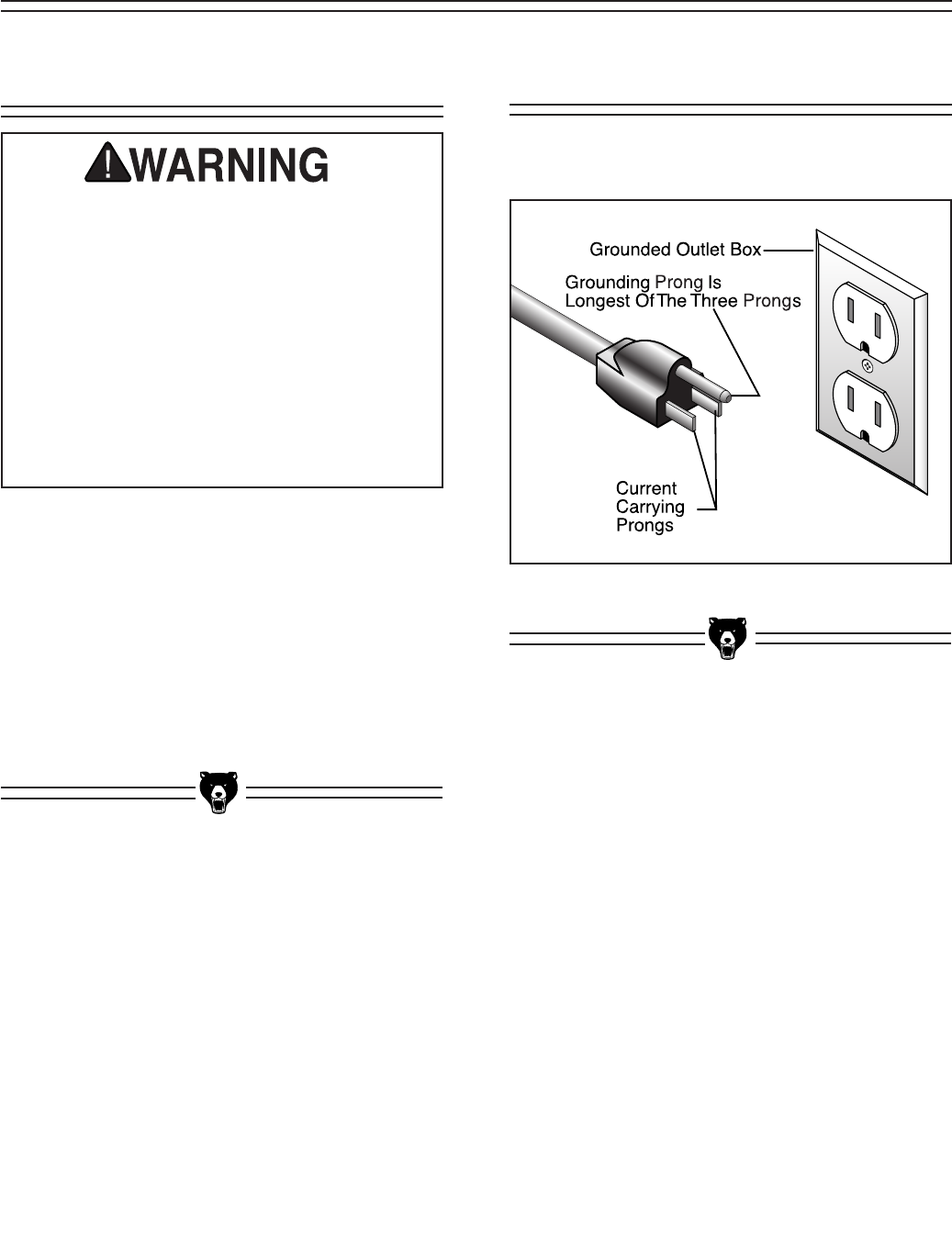
The power switch plugs into a wall outlet that is
properly grounded as shown in Figure 1.
If the machine is wired incorrectly a fire
could result. Make sure your wiring, recep-
tacle, plug, and circuit breaker can handle
the current draw of the machine. If you are
not sure that your electrical circuit can han-
dle the current draw, get a qualified electri-
cian to test your electrical system and do
any required upgrades. Do not attempt to
modify an existing circuit by only replac-
ing the circuit breaker with one rated for
a higher amperage draw than the wiring,
receptacle, and plug are rated for.
Figure 1. A 3-prong plug and ground outlet.
Electrical
General
SECTION 3: CIRCUIT REQUIREMENTS
G0528 Sliding Router Table -7-
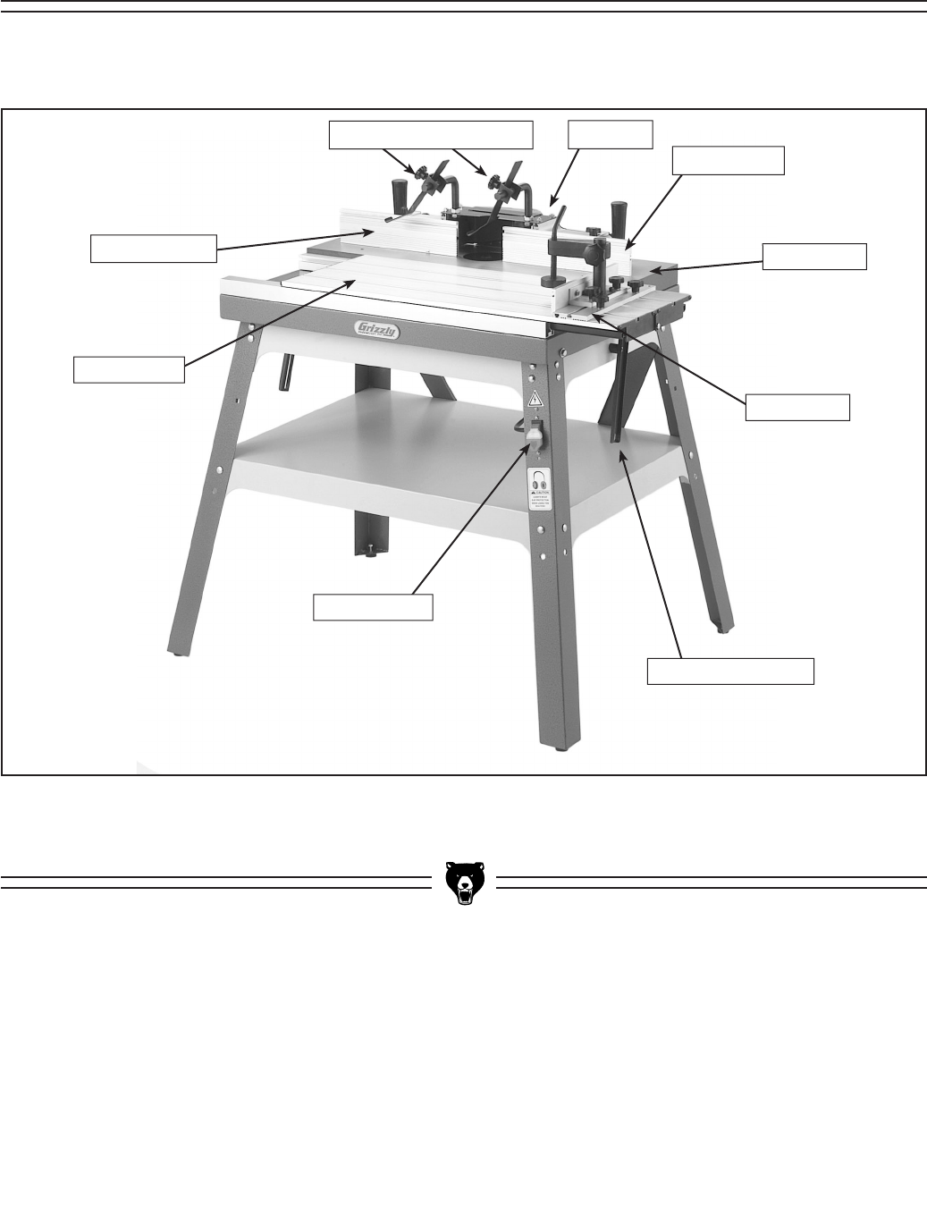
Set up and operation instructions will be easier to understand if you become familiar with the location and
names of the machine features shown in Figure 2.
Figure 2. Machine features.
Sliding Table
Power Switch
Main Table
Table Tilt Brackets
Miter Gauge
Dust Port
Infeed Fence
Outfeed Fence
Workpiece Hold-Downs
SECTION 4: MACHINE FEATURES
-8- G0528 Sliding Router Table
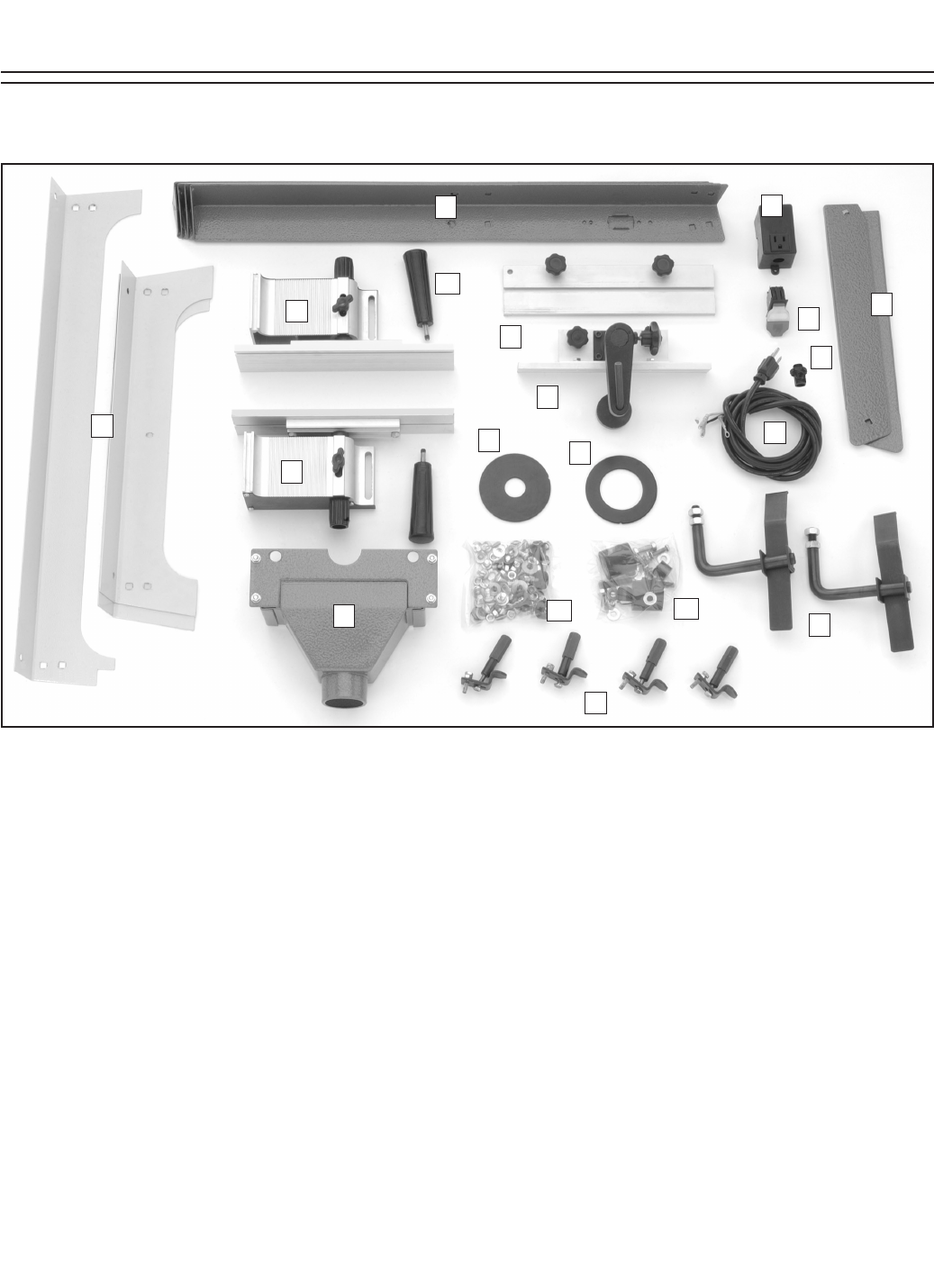
A. Left Fence .....................................................1
B. Right Fence ...................................................1
C. Dust Hood .....................................................1
D. Power Cord ...................................................1
E. Switch ............................................................1
F. Switch Box .....................................................1
G. Workpiece Hold-Downs .................................2
H. Miter Plate .....................................................1
I. Miter Fence ...................................................1
J. Router Clamps ..............................................4
K. 29MM Table Insert ........................................1
L. 60MM Table Insert ........................................1
M. Fence Lock Handles ......................................2
N. Hardware Bag
— Rubber Stops .........................................2
— Phillips Screws 1⁄4"-20 x 11⁄2" ..................2
— Flat Washers 1⁄4" .....................................4
— Hex Nuts 1⁄4"-20 ......................................2
— Hex Bolts 5⁄16"-18 x 1" .............................2
— Hex Nuts 5⁄16"-18 .....................................4
Figure 3. G0528 Inventory.
— Flat Washers 5⁄16" ....................................8
— Cap Screws 5⁄16"-18 x 11⁄2" ......................2
— Spacers ..................................................2
O. Hardware Bag
— Carriage Bolts 5⁄16"-18 x 1⁄2" ...................32
— Flat Washers 5⁄16" ..................................32
— Lock Washers 5⁄16" ................................32
— Hex Nuts 5⁄16"-18 ...................................32
— Rubber Feet ...........................................4
— Phillips Screws 1⁄4"-20 x 1" .....................4
— Flat Washers 1⁄4" .....................................4
— Hex Nuts 1⁄4"-20 ......................................4
P. Diagonal Supports ..........................................2
Q. Stand Legs ....................................................4
R. Cross Supports ..............................................4
S. Strain Relief ...................................................1
DESCRIPTION QTY
DESCRIPTION QTY
A
B
C
E
D
F
G
P
Q
R
H
I
J
KL
M
N
O
G0528 Inventory
SECTION 5: SET UP
S
G0528 Sliding Router Table -9-
5mm
10mm
15mm
20mm
25mm
30mm
35mm
40mm
45mm
50mm
55mm
60mm
65mm
70mm
75mm
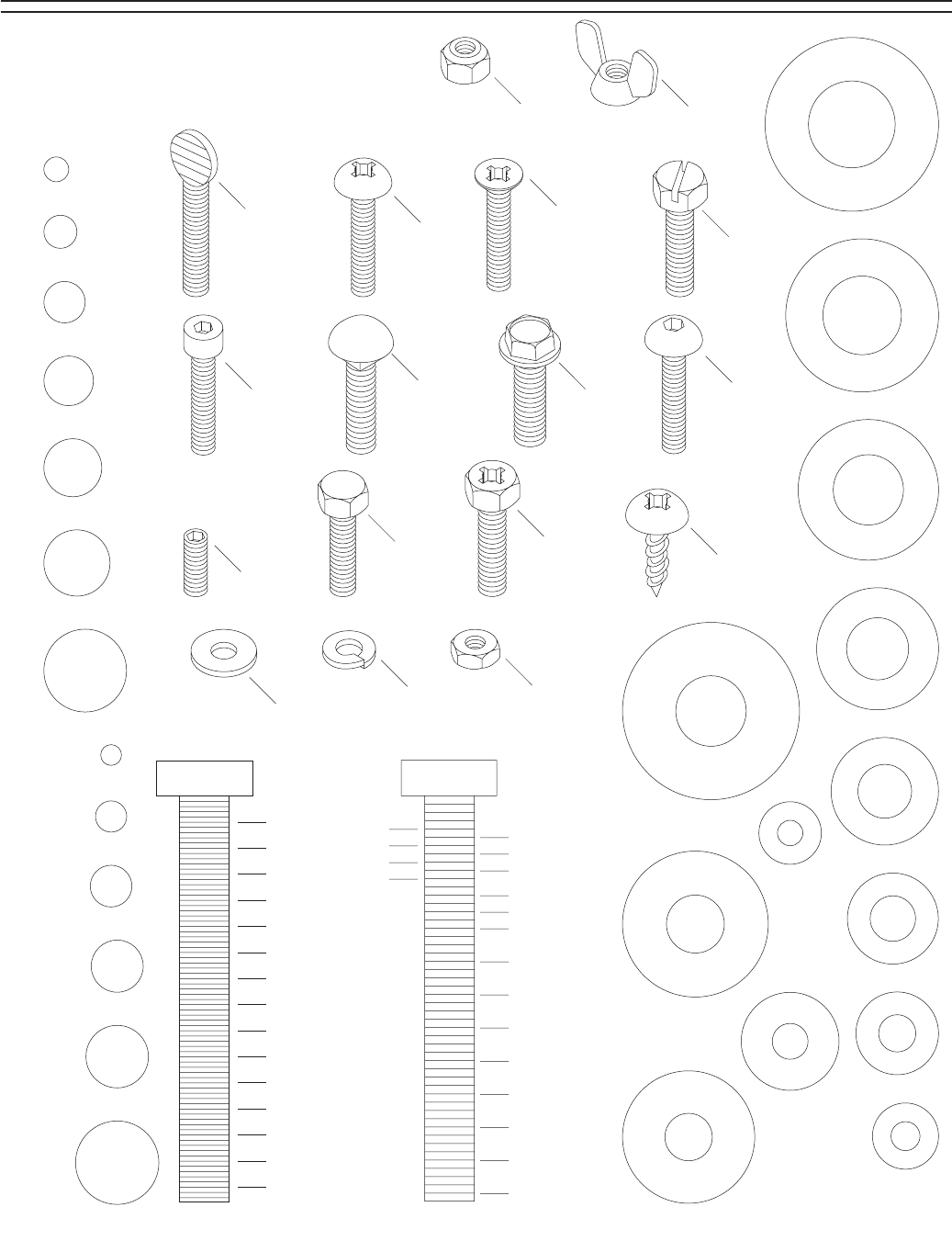
Washer
Lock
Washer Hex
Nut
Wing
Nut
Phillips
Head
Sheet
Metal
Screw
Setscrew
Phillips
Head
Screw
Thumb
ScrewSlotted
Screw
Flat Head
Phillips
Screw
Cap
Screw
Carriage
Bolt
Hex
Head
Bolt
Button
Head
Screw
Flange
Bolt
Phillips
Head
Hex
Bolt
Lock
Nut
5⁄16''
1⁄4''
3⁄8''
1⁄2''
5⁄8''
7⁄16''
9⁄16''
3⁄4''
7⁄8''
1''
11⁄4''
11⁄2''
13⁄4''
2
21⁄4''
21⁄2''
23⁄4''
3
LINES ARE 1MM APART
LINES ARE 1⁄16'' INCH APART
5⁄8''
W
A
S
H
E
R
D
I
A
M
E
T
E
R
9⁄16''
W
A
S
H
E
R
D
I
A
M
E
T
E
R
1⁄2''
W
A
S
H
E
R
D
I
A
M
E
T
E
R
12mm
W
A
S
H
E
R
D
I
A
M
E
T
E
R
10mm
W
A
S
H
E
R
D
I
A
M
E
T
E
R
7⁄16''
W
A
S
H
E
R
D
I
A
M
E
T
E
R
8mm
W
A
S
H
E
R
D
I
A
M
E
T
E
R
3⁄8''
W
A
S
H
E
R
D
I
A
M
E
T
E
R
5⁄16''
W
A
S
H
E
R
D
I
A
M
E
T
E
R
1⁄4''
W
A
S
H
E
R
D
I
A
M
E
T
E
R
#10
W
A
S
H
E
R
D
I
A
M
E
T
E
R
4mm
W
A
S
H
E
R
D
I
A
M
E
T
E
R
6mm
W
A
S
H
E
R
D
I
A
M
E
T
E
R
WASHERS ARE MEASURED BY THE INSIDE DIAMETER
MEASURE BOLT DIAMETER BY PLACING INSIDE CIRCLE
#10
1⁄4''
5⁄16''
3⁄8''
7⁄16''
1⁄2''
5⁄8''
4mm
6mm
8mm
10mm
12mm
16mm
USE THIS CHART TO MATCH UP
HARDWARE DURING THE ASSEMBLY
PROCESS!
Hardware Recognition Chart
-10- G0528 Sliding Router Table
Metal components are often coated with a wax
or oil to prevent rusting during shipment. Clean
all coated parts with a solvent cleaner or cit-
rus-based degreaser such as Grizzly’s G7895
Degreaser. To clean thoroughly, some parts may
need to be removed. For optimum performance
from your machine, make sure you clean all
moving parts or sliding contact surfaces that
are coated. Avoid chlorine-based solvents as
they may damage painted surfaces should they
come in contact.
Gasoline and petroleum
products have low flash
points and could explode
if used to clean machin-
ery. DO NOT use gasoline
or petroleum products to
clean the machinery.
Smoking near solvents
could ignite an explosion
or fire and cause serious
injury. DO NOT smoke
while using solvents.
Lack of ventilation while
using solvents could
cause serious person-
al health risks, fire, or
environmental hazards.
Always work in a well
ventilated area to pre-
vent the accumulation
of dangerous fumes.
Supply the work area
with a constant source
of fresh air.
Unsupervised children and
visitors inside your shop
could receive serious per-
sonal injury. Ensure child
and visitor safety by keep-
ing all entrances to the
shop locked at all times.
DO NOT allow unsuper-
vised children or visitors
in the shop at any time.
Weight Load
The Model G0528 weighs 125 lbs. Most shop
floors should be sufficient to carry the weight of
the machine. Reinforce the floor if you question
its ability to support the weight.
Working Clearance
Working clearances can be thought of as the
distances between machines and obstacles that
allow safe operation of every machine with-
out limitation. Consider existing and anticipated
machine needs, size of material to be processed
through each machine, and space for auxiliary
stands or work tables. Also, consider the relative
position of each machine to one another for effi-
cient material handling.
Lighting And Outlets
Lighting should be bright enough to eliminate
shadow and prevent eye strain. Electrical circuits
should be dedicated or large enough to handle
the amperage draw. Outlets should be located
near each machine so power or extension cords
are clear of high-traffic areas. Observe local elec-
trical codes for proper installation of new lighting,
outlets, or circuits.
Site ConsiderationsClean Up
G0528 Sliding Router Table -11-
This section covers the basic assembly and
adjustment instructions needed to begin opera-
tion. Complete the assembly in the order pro-
vided in this manual and then read the remaining
portion of the manual before attempting any type
of operation.
Your safety is important! Please follow the
warnings below during this entire section:
Loose hair and cloth-
ing could get caught
in machinery causing
serious personal inju-
ry. Keep loose clothing
rolled up and long hair
tied up and away from
machinery.
Projectiles thrown from
the machine could cause
serious eye injury. Wear
safety glasses during
assembly.
Disconnect power to
the machine during the
entire assembly process.
Failure to do this may
result in serious person-
al injury.
!
Sharp edges on metal
parts may cause personal
injury. Examine the edges
of all metal parts before
handling.
Components Needed: Qty
Rubber Feet .......................................................4
Phillips Screws 1⁄4"-20 x 1" .................................4
Hex Nuts 1⁄4"-20 ..................................................4
Flat Washers 1⁄4" .................................................4
Tools Needed:
10mm Wrench or Socket ....................................1
Phillips Head Screwdriver ..................................1
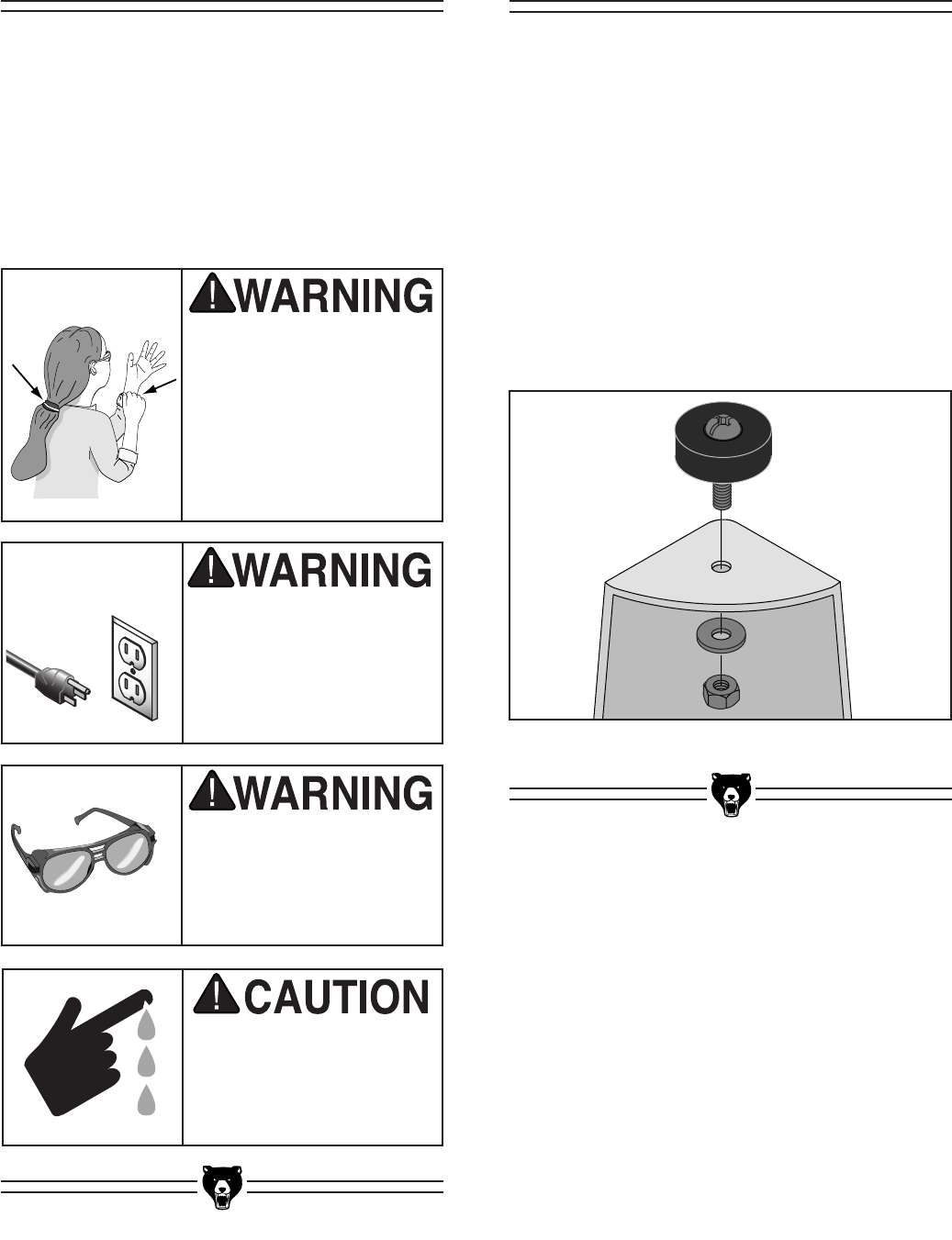
To install the rubber feet:
Secure the rubber feet to the stand legs with the
Phillips screws, the hex nuts, and the flat washers
(Figure 4).
Figure 4. Rubber feet installation.
Rubber FeetAssembly
-12- G0528 Sliding Router Table
Cross Supports
Components Needed: Qty
Table Assembly ..................................................1
Table Cross Supports .........................................3
Rubber Stops .....................................................2
Cap Screws 5⁄16"-18 x 11⁄2" ..................................2
Flat Washers 5⁄16" ................................................8
Hex Nuts 5⁄16"-18 .................................................4
Hex Bolts 5⁄16"-18 x 1" .........................................2
Tools Needed:
12mm Wrench or Socket ....................................1
6mm Allen Wrench .............................................1
To attach the table to the stand:
1. Place the table assembly face-down on the
floor.
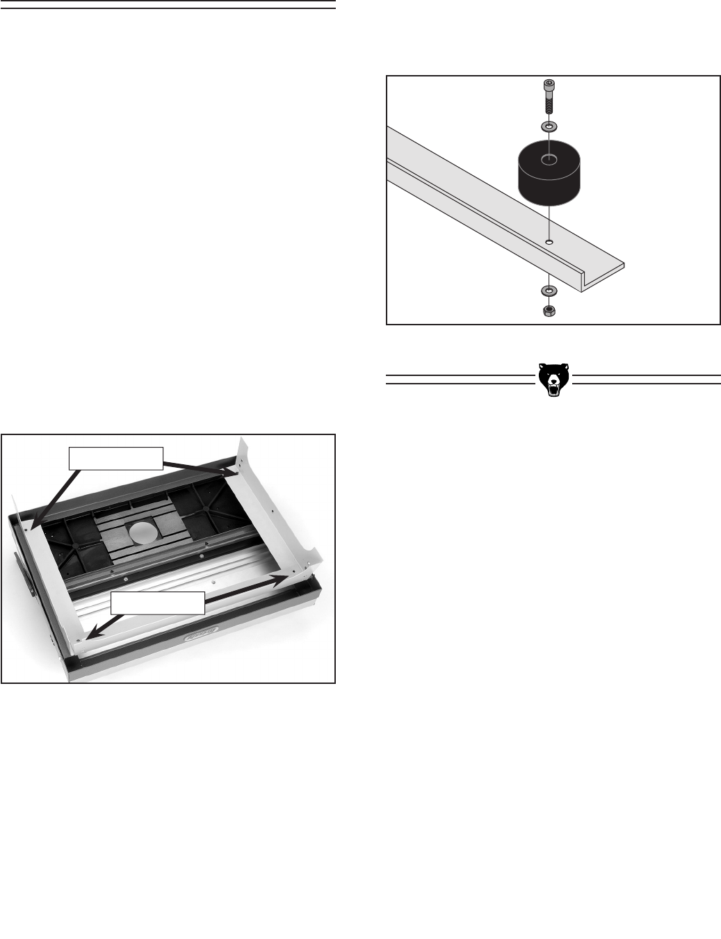
2. Position the table cross supports on the table
assembly and align the bolt holes (Figure
5).
Figure 5. Table cross supports.
3. Secure bolt holes “A” (Figure 5) with 2 hex
bolts, 4 flat washers, and 2 hex nuts.
4. Secure bolts holes “B” (Figure 5) with the
rubber stops, 2 cap screws, 4 flat washers,
and 2 hex nuts (Figure 6).
Figure 6. Securing cross supports to table.
Bolt Holes “A”
Bolt Holes “B”

G0528 Sliding Router Table -13-
Components Needed: Qty
Stand Legs .........................................................4
Diagonal Supports ..............................................2
Tray ....................................................................1
Carriage Bolts 5⁄16"-18 x 1⁄2" ...............................32
Flat Washers 5⁄16" ..............................................32
Lock Washers 5⁄16" ............................................32
Hex Nuts 5⁄16"-18 ...............................................32
Tools Needed:
12mm Wrench or Socket ....................................1
To assemble the stand:
1. Secure the stand legs to the table cross sup-
ports with 12 carriage bolts, 12 flat washers,
12 lock washers, and 12 hex nuts. Note—
The stand leg with the switch cut-out should
be facing the front of the machine.
2. Secure the tray to the stand legs with 16 car-
riage bolts, 16 flat washers, 16 lock washers,
and 16 hex nuts.
3. Secure the diagonal supports (Figure 7) to
the stand legs and the tray with 4 carriage
bolts, 4 flat washers, 4 lock washers, and 4
hex nuts.
Figure 7. Table diagonal support positions.
Components Needed: Qty
Spacers ..............................................................2
Phillips Head Screws 1⁄4"-20 x 11⁄2" .....................2
Flat Washers 1⁄4" .................................................4
Hex Nuts 1⁄4"-20 ..................................................2
Tools Needed:
Phillips Head Screwdriver ..................................1
Adjustable Wrench .............................................1
To assemble the braces:
1. Slide a washer over the screws.
2. Slide the screws through each brace.
3. Thread the screws through the spacers.
Note—Allow just enough of a gap between
the washers and the spacers for the table
braces to slide freely.
4. Secure the screw/spacer assemblies to the
stand with the washers and the hex nuts.
Figure 8. Assembling the table braces.
SPECIFICATIONS
FAILURE TO FOLLOW THESE WARNINGS WILL RESULT IN SERIOUS PERSONAL INJURY:
1. READ AND UNDERSTAND THE ROUTER AND ROUTER
TABLE MANUAL BEFORE STARTING THE MACHINE.
2. ALWAYS WEAR EYE PROTECTION AND A RESPIRATOR.
3. PLUG POWER CORD INTO GROUNDED OUTLET ONLY.
4.
ALWAYS KEEP HANDS OUT OF THE CUTTER PATH.
5. KEEP ALL GUARDS IN PLACE AT ALL TIMES.
6.
DO NOT WEAR LOOSE CLOTHING, GLOVES OR JEWELRY.
SECURE LONG HAIR AND BUTTON ALL LONG SLEEVE
SHIRTS.
7. DISCONNECT POWER PRIOR TO SERVICING, CHANGING
CUTTERS OR ADJUSTING FENCE AND MITER GAUGE.
8. DO NOT EXPOSE TO RAIN OR DAMPNESS.
9. DO NOT OPERATE UNDER THE INFLUENCE OF DRUGS
OR ALCOHOL.
10. MAKE SURE MACHINE IS PROPERLY ADJUSTED AND SET
UP CORRECTLY BEFORE STARTING MOTOR.
11. BEFORE STARTING MACHINE, MAKE CERTAIN IT RESTS
SECURELY ON FLAT, LEVEL GROUND.
12. KNOW HOW TO AVOID RISK OF KICKBACK.
13. DO NOT REMOVE JAMMED OR CUT-OFF WORKPIECE
WHILE CUTTER IS TURNING.
14. BEFORE STARTING MACHINE, MAKE SURE CUTTER IS
INSTALLED CORRECTLY AND PROPERLY TIGHTENED.
15. NEVER MAKE FREE-HAND CUTS. ALWAYS USE THE
FENCE OR MITER.
16. BEFORE STARTING MACHINE, ALWAYS CHECK FEED
DIRECTION.
17. MAKE SURE CUTTER HAS COME TO A COMPLETE STOP
PRIOR TO MAKING ANY ADJUSTMENTS.
18. NEVER ATTEMPT TO REMOVE TOO MUCH MATERIAL IN
ONE PASS.
G0528
SLIDING ROUTER TABLE
UNIVERSAL ROUTER MOUNTING SYSTEM
TABLE INSERT DIAMETERS: 1-1/8", 2-5/16"
TABLE COUNTERBORE: 3-1/2"
DUST PORT: 2-1/2"
STAND: POWDER-COATED STEEL
WEIGHT: 125 LBS.
Date
Serial Number
Manufactured for Grizzly in Taiwan
READ AND UNDERSTAND THE
ROUTER AND ROUTER TABLE
OPERATOR'S MANUAL BEFORE
USING THIS MACHINE. FAILURE
TO FOLLOW OPERATING
INSTRUCTIONS WILL RESULT IN
DEATH OR SERIOUS PERSONAL
INJURY.
Table BracesStand
Hands and fingers can become seriously
injured if they are pinched between the
stand edge and the table. DO NOT place
hands or fingers near the stand edge while
the table is in the raised position.
-14- G0528 Sliding Router Table
Components Needed: Qty
Left Fence .........................................................1
Right Fence ........................................................1
Dust Hood ..........................................................1
Fence Lock Handles ...........................................2
Tools Needed:
10mm Wrench or Socket ....................................1
11mm Wrench or Socket ....................................1
To attach the fence assembly:
1. Secure the left and right fence assemblies
to the table with the fence lock handles.
Note—Use the holes located closest to the
edge of the cast iron table.
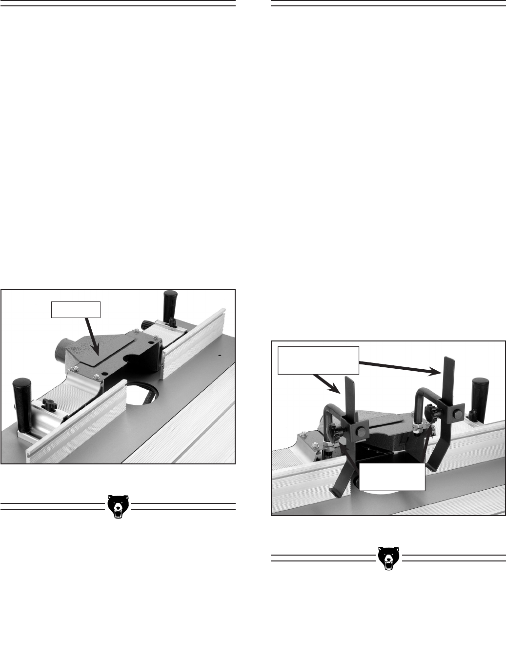
2. Secure the dust hood to the top of each
fence assembly (Figure 9).
Figure 9. Installed fence and dust hood.
Dust Hood
Components Needed: Qty
Workpiece Hold-Down Assemblies ....................2
Tools Needed:
19mm Wrench ....................................................1
To attach the hold-downs:
1. Remove one of the hex bolts from each of
the hold-down brackets.
2. Slide the hold-down brackets through the
mounting holes on the dust cover and secure
them from the underside of the dust cover
with the hex nuts removed in step 1.
3. Tighten the hex nuts until the hold-down
brackets are secure.
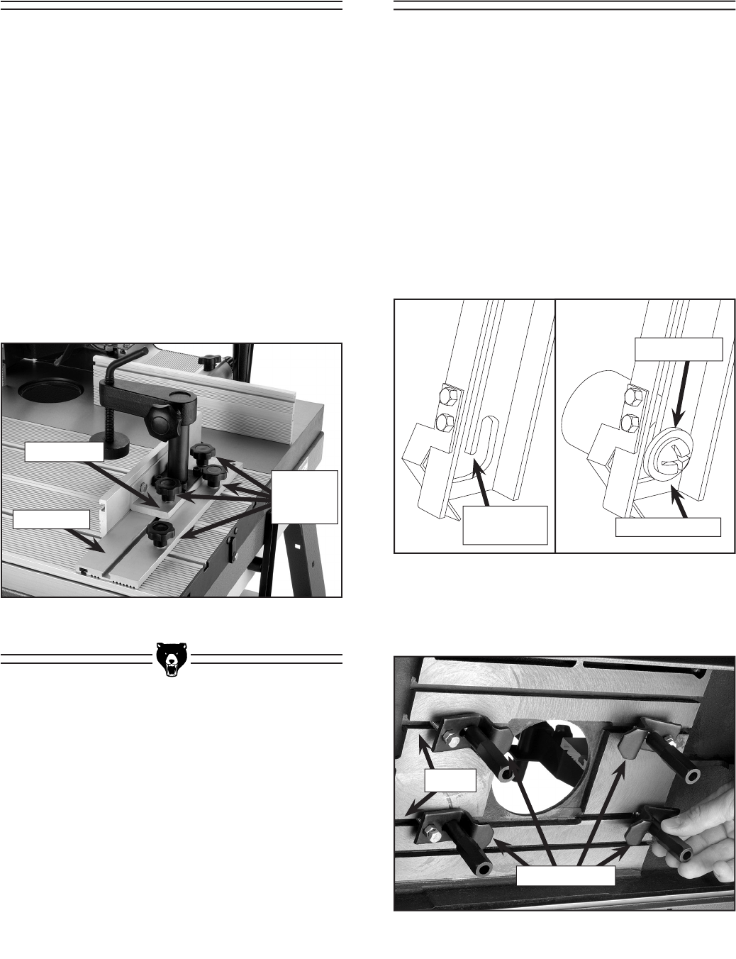
4. Secure the hold-down finders to the hold-
down brackets by tightening the threaded
star knob (Figure 10). Note—Do not worry
about precise placement of the hold-down
brackets or fingers at this time.
Figure 10. Installed hold-down assemblies.
Workpiece Hold-
Down Assemblies
Threaded Star
Knobs
Hold-DownsFence
G0528 Sliding Router Table -15-
Components Needed: Qty
Miter Fence ........................................................1
Miter Plate ..........................................................1
To attach the sliding table:
1. Secure the miter plate to the sliding table by
sliding the T-bolts into the table T-track.
2. Position the miter plate in the desired posi-
tion and tighten the threaded star knobs.
Note—Do not worry about precise placement
of the of the miter plate at this time.
3. Secure the miter fence to the miter plate with
the threaded star knobs (Figure 11).
Figure 11. Installed sliding table fence.
Miter Plate
Miter Fence
Threaded
Star
Knobs
Figure 12. Locked table brace.
Components Needed: Qty
Router Clamps ...................................................4
Tools Needed:
10mm Wrench ....................................................1
14mm Wrench ....................................................1
To attach the router to the table:
1. Lift the table assembly up and engage the
table braces on each side. Note—Ensure
that the table brace lock tabs are engaged
completely around the lock screws (Figure
12).
2. Slide each of the four router clamps into the
T-slots on the underside of the cast iron table
(Figure 13).
Figure 13. Installing the router clamps
Router Clamps
T-Slots
Router To TableMiter
Locked Position
Lock Screw
Table Brace
Lock Tab
-16- G0528 Sliding Router Table
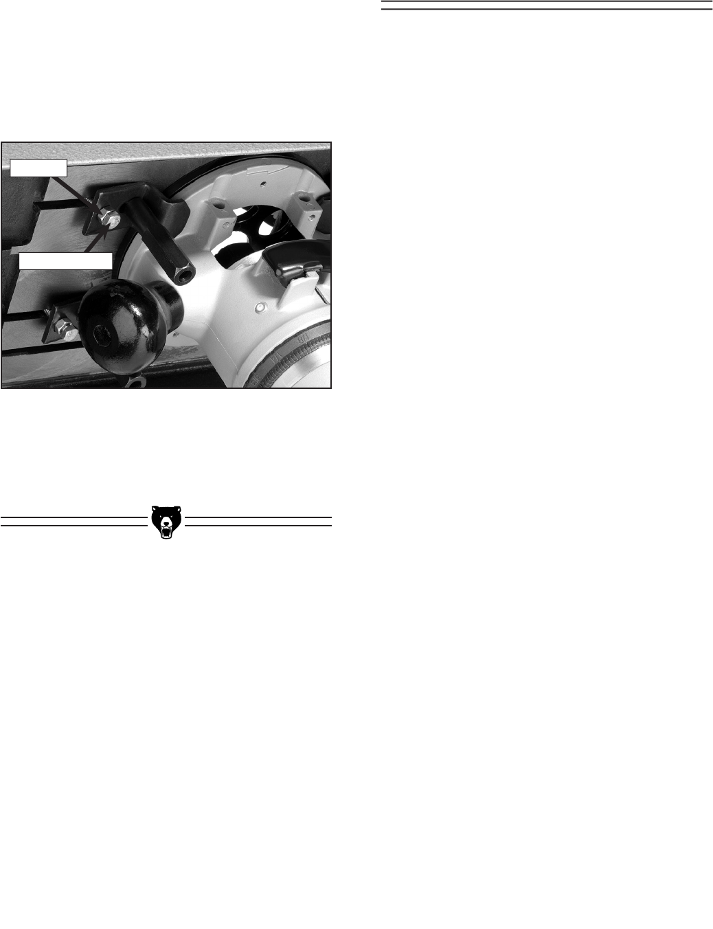
5. Tighten the router clamps to secure the
router base into position.
Figure 14. Adjust the router clamp
thickness bolts.
Thickness Bolt
Jam Nut
Components Needed: Qty
Switch .................................................................1
Switch Box ..........................................................1
Power Cord ........................................................1
Strain Relief ........................................................1
Tools Needed:
Phillips Head Screwdriver ..................................1
Adjustable Wrench .............................................1
To attach the switch to the stand leg:
1. Install the strain relief on the outside of the
switch, using the plastic nut from the inside
to secure the strain relief to the switch box.
2. Feed the power wires through the strain relief
and tighten the strain relief screw against the
main cord jacket.
3. Secure the green ground wires from the
power cord and the switch box to the stand
leg, using the Phillips head screw and hex
nut already installed in the frame.
4. Push the switch through the cut-out on the
stand leg.
Switch
3. Loosen the router clamps enough to allow
the base of the router to press flat against the
underside of the cast iron table. Note—The
router spindle should be centered under the
cut out in the cast iron table.
4. Adjust the thickness bolts and the jam nuts
on each of the router clamps to allow the
router base to be secured against the table
(Figure 14).
G0528 Sliding Router Table -17-
DO NOT use the router table without adequate
dust collection. Hook the dust port up to a shop
vacuum or dust collection system.
Dust Port Hook-Up
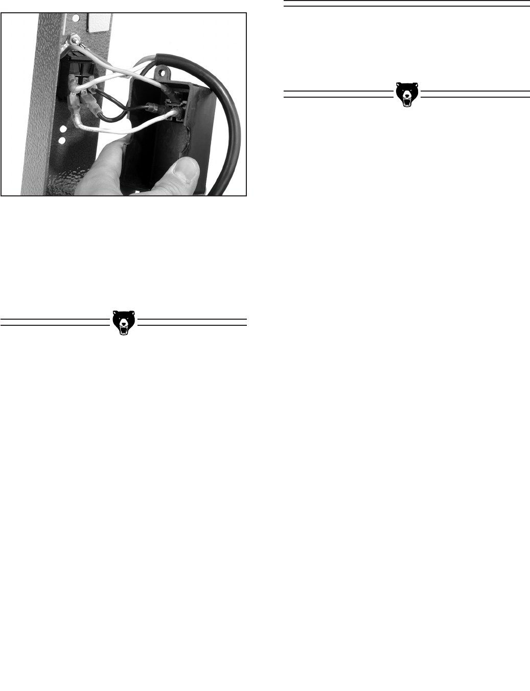
Figure 15. Securing the power wires
to the switch.
5. Attach the black and white power wires to the
back of the switch (Figure 15), at the clips
labeled “B” and “W."
6. Secure the switch box to the back of the
switch using the Phillips head screws, the
external toothed washers, and the hex nuts
already installed in the frame.
-18- G0528 Sliding Router Table
Your safety is important! Please follow the
warnings below during this entire section:
To avoid serious personal injury, read and
become familiar with the entire instruction
manual before using the Model G0528.
Damage to your eyes, lungs, and ears
could result from failure to wear safety
glasses, a respirator, and hearing protec-
tion while using this machine.
Loose hair and cloth-
ing could get caught in
machinery and cause
serious personal inju-
ry. Keep loose clothing
rolled up and long hair
tied up and away from
machinery.
Routing operations on your Model G0528 are
grouped into three main techniques:
• Jointing an edge (page 18)
• Groove cutting (page 19)
• Profile cutting (page 19)
Jointing an edge:
Jointing the edge of a board involves using a
straight cutting router bit to remove wood from the
edge face of a board. The result is a perfectly flat
and square edge.
1. Secure a straight cutting router bit into your
router according to the router manufacturer’s
instructions.
2. Snap the smallest table insert into the
recessed hole that still allows the router bit
to freely rotate.
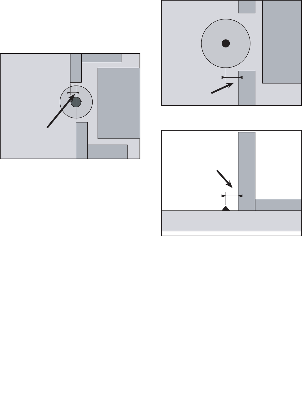
3. Adjust the outfeed fence even with the left
edge of the router bit (Figure 16).
Figure 16. Jointing setup.
(Top View)
Routing
Before Routing
SECTION 6: OPERATIONS
G0528 Sliding Router Table -19-
4. Raise the bit to a height slightly higher than
that of the board thickness.
5. Adjust the infeed fence to the right of the
outfeed fence, so that the distance is equal
to the desired depth of cut (Figure 17).
Figure 17. Jointing setup.
(Top View)
Depth Of Cut
Groove cutting:
Beading is commonly defined as cutting a groove
or bead in the face of a board.
1. Mount a router bit into your router according
to the router manufacturer’s instructions.
2. Snap the smallest table insert into the
recessed hole that still allows the router bit
to freely rotate.
3. Raise the router bit to the desired height.
4. Adjust the main fence until the center of the
V-groove bit is the desired distance away as
shown in Figure 18 & 19.
Figure 18. Groove cutting setup.
(Top View)
Distance From
Edge Of Board
To Center Of
V-Groove
Figure 19. Groove cutting setup.
(Side View)
Distance From
Edge Of Board
To Center Of
V-Groove
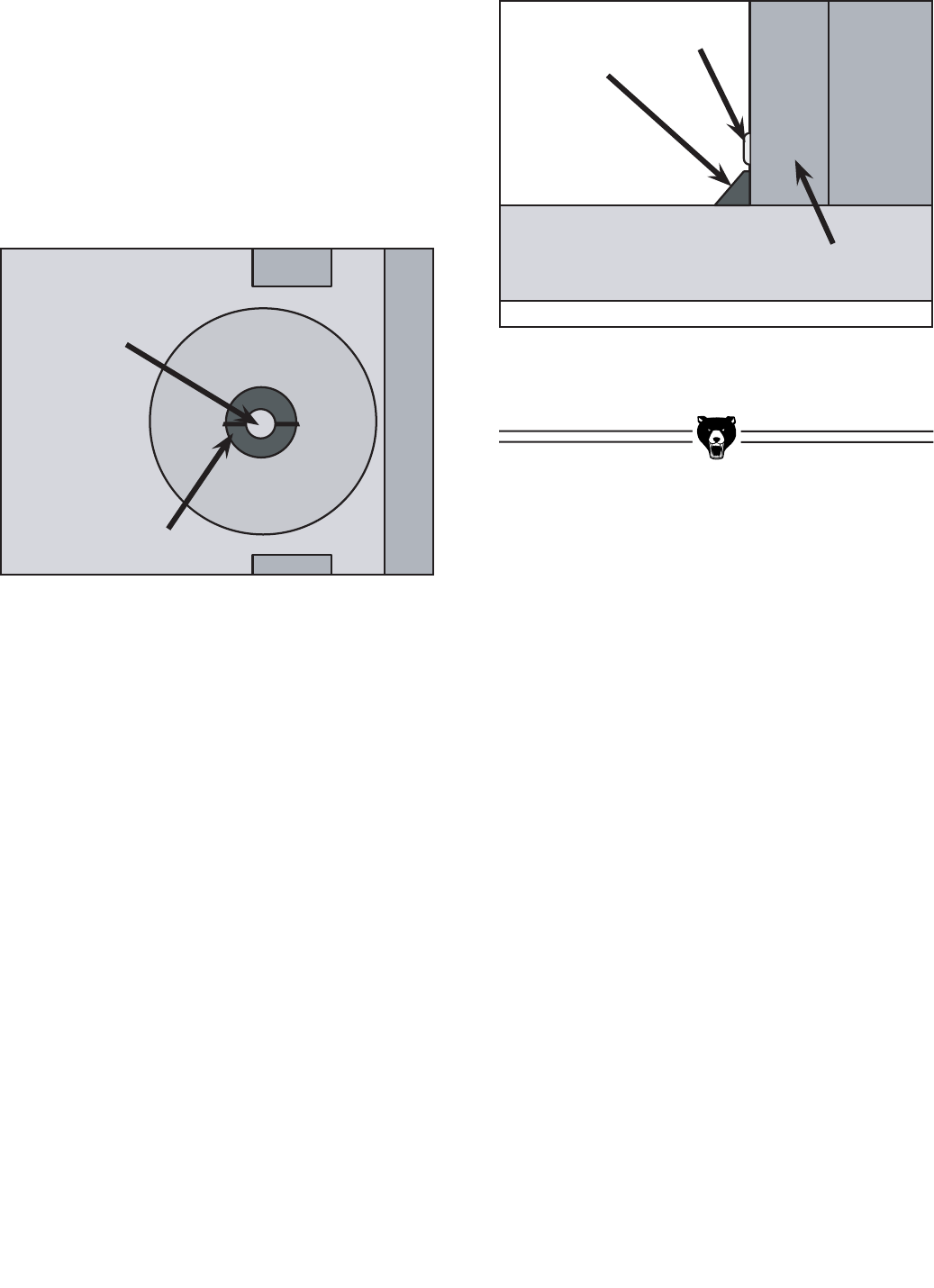
Profile cutting:
Profile cutting is usually performed using a bit
with a ball bearing. The ball bearing is used to
control the depth of cut into the edge face of a
board. A good example would be a chamfer cut.
The bearing rides along the uncut edge of the
board while the cutter removes the wood.
1. Mount a router bit into your router according
to the router manufacturer’s instructions.
2. Snap the smallest table insert into the
recessed hole that still allows the router bit
to freely rotate.
-20- G0528 Sliding Router Table
3. Raise the router bit to the desired height.
4. Adjust the fence back and away from the bit
only enough to allow the ball bearing to con-
trol the depth of cut as shown in Figures 20
& 21.
5. Adjust the fence as close as possible to the
bearing. The fence will serve as a back-up
support, reducing the chance of an accident.
Figure 20. Proper setup for profile cutting.
(Top View)
Figure 21. Proper setup for profile cutting.
(Side View)
Router Bit
Ball Bearing
Router Bit
Fence
Ball Bearing

G0528 Sliding Router Table -21-
If you need parts or help in assembling your
machine, or if you need operational information,
call the Grizzly Service Department. Trained ser-
vice technicians will be glad to help you.
If you have any comments regarding this manual,
please write to Grizzly at the address below:
Grizzly Industrial, Inc.
C/O Technical Documentation
P.O. Box 2069
Bellingham, WA 98227-2069
Important safety measures that are essential
to the operation of this machine have been
explained in Section 1: Safety. While most safe-
ty measures are generally universal, Grizzly
reminds you that each workshop is different and
safety rules should be considered as they apply
to your specific situation.
We recommend you keep a copy of our cur-
rent catalog for complete information regarding
Grizzly's warranty and return policy. If you need
additional technical information relating to this
machine, or if you need general assistance or
replacement parts, please contact the Service
Department at the location listed below.
Grizzly Industrial, Inc.
1203 Lycoming Circle
Muncy, PA 17756
Phone: (570) 546-9663
Fax: (800) 438-5901
E-Mail: techsupport@grizzly.com
Web Site: http://www.grizzly.com.
Additional information sources are necessary to
realize the full potential of this machine. Trade
journals, woodworking magazines, and your local
library are good places to start.
SECTION 7: REFERENCE INFO

-22- G0528 Sliding Router Table
Customer Service #: (570) 546-9663 • To Order Call: (800) 523-4777 • Fax #: (800) 438-5901
G0528 Machine Data Sheet
MACHINE DATA
SHEET
Design Type ..................................................................................................... Floor Model
Overall Dimensions:
Main Table ................................................................................31" W x 10" D x 13⁄4" T
Sliding Table .......................................................................................... 31" W x 12" D
Total Table Surface ................................................................................ 31" W x 22" D
Overall Height ...................................................................................................... 42" H
Height From Table To Floor ................................................................................. 34" H
Overall Width ........................................................................................................ 40"W
Overall Length ...................................................................................................... 30" D
Shipping Weight ............................................................................................... 132 lbs.
Net Machine Weight ......................................................................................... 125 lbs.
Box Size ................................................................................... 351⁄2" W x 26" D x 8" H
Footprint ................................................................................................. 40" W x 30" D
Capacities:
Suitable Routers For Mounting ................................................................. 3⁄4 HP - 5 HP
Table Counterbore ..................................................................................................31⁄2"
Table Insert Diameters ................................................................................ 11⁄8" & 25⁄16"
Fence Size ..................................................................................3" x 12" (Each Piece)
Maximum Fence Working Surface ....................................................................3" x 36"
Dust Port .................................................................................................................21⁄2"
Construction:
Main Table ....................................................................... Precision-Ground Cast Iron
Sliding Table ................................................................................................. Aluminum
Fence Assembly ............................................................................... Aluminum & Steel
Stand ...........................................................................................Powder-Coated Steel
Miter Body ..................................................................................................... Aluminum
Features:
................................................................................................ Workpiece Hold-Downs
..................................................................................................Clamping Miter Gauge
........................................................................................ Toggle Switch W/Safety Key
................................. Dual Power Outlets For Convenient Router/Accessory Plug-Ins
......................................................................45˚ Table Tilt For Easy Router Mounting
................................................................................................................. Sliding Table
Specifications, while deemed accurate, are not guaranteed.
8/2003
MODEL G0528 ROUTER TABLE
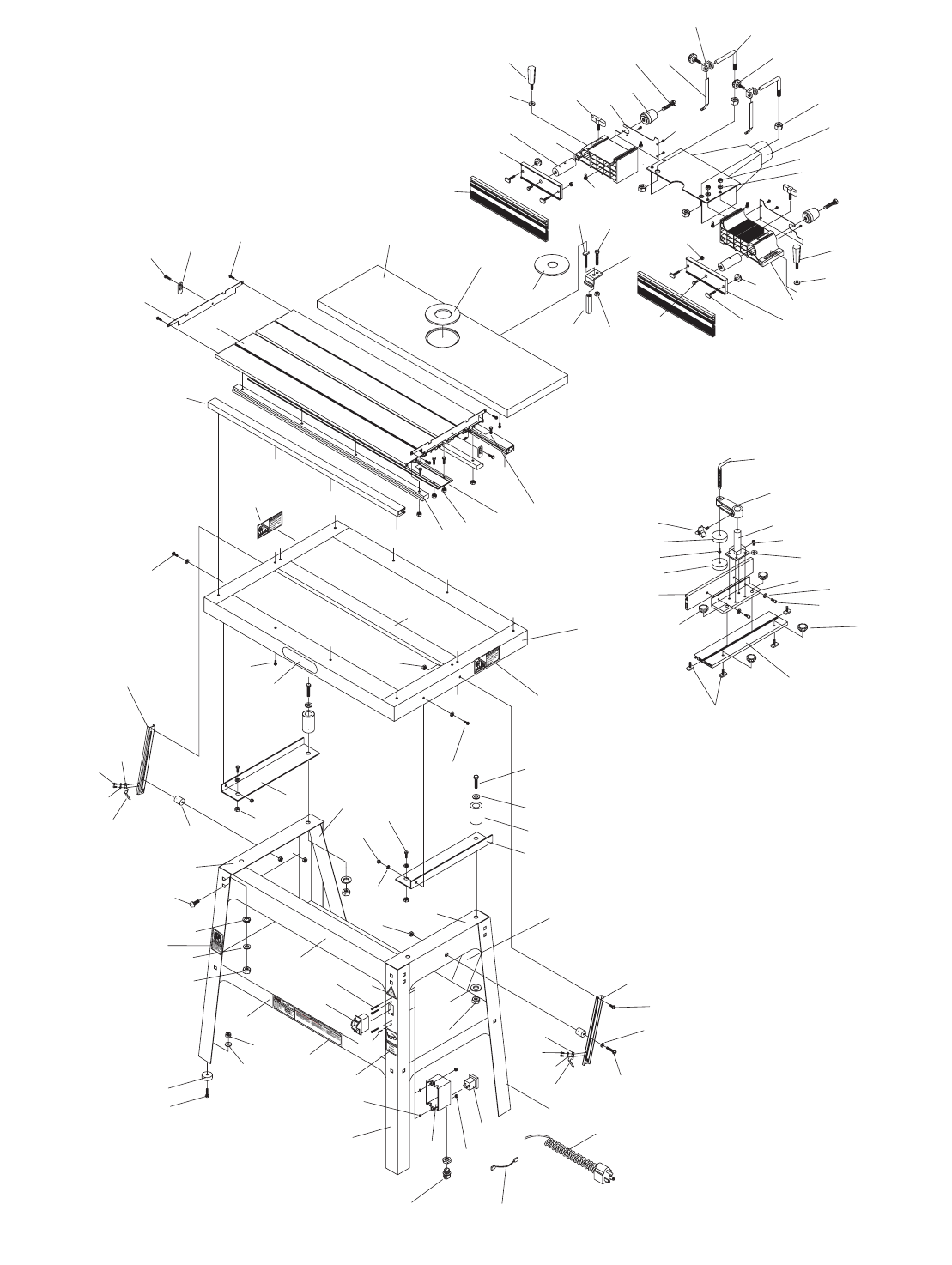
G0528 Sliding Router Table -23-
304
313
303
311
307
308
312
315
142
323
146
302
318-1
318 143
320
319
301
145
305
230
314
317
337
147
308
316
307
230
308
307
333
142
139
142
306
127
119
120
125
328
228
136
216
217
209
219
140
201
202 218
140
212
210
211
203
111
144
335
314
324
310
215
307
309
223
200
342
213
220
222
136
135
134
334
123
129
221
138
230
224
140
139
112
126
137-1
124
133
137
131
132
112
139
128
314
140
129
307
130
115
113
307
128
130
121
114
122
116
141
118
117
230
314
330
330
329
326 327
331
332
225
227
226
148
225
227
226
336
G0528 Parts Breakdown

-24- G0528 Sliding Router Table
111 P0528111 FENCE HALF
112 P0528112 T-BOLT 1/4-20 X 3/4"
113 P0528113 MICRO-ADJUSTMENT ROD
114 P0528114 FENCE BODY (LEFT)
115 P0528115 FENCE BODY GUARD
116 P0528116 MICRO-ADJUSTMENT NUT
117 P0528117 HOLD-DOWN BRACKET
118 P0528118 HOLD-DOWN
119 P0528119 L-BRACKET
120 P0528120 KNOB BOLT 5/16-18 X 5/8"
121 P0528121 HANDLE BOLT 3/8-16 X 3/4"
122 PB16 HEX BOLT 3/8-16 X 1-1/2"
123 P0528111 FENCE PLATE
124 P0528112 CLAMP HOLDER
125 P0528113 DUST HOOD
126 P0528114 SHORT FENCE
127 PN34 HEX NUT 1/2-12
128 P0528128 CLAMP PLATE
130 P0528130 HEAVY HANDLE
131 P0528131 CLAMP BRACKET
132 P0528132 BRACKET
133 P0528133 CLAMP ROD
134 P0528134 HANDLE BOLT 1/4-20 X 5/8"
135 P0528135 CLAMP PLATE
136 PS06 PHLP HD SCR 10-24 X 3/8"
REF PART # DESCRIPTION
137 PSB04 CAP SCREW 1/4-20 X 1/2"
137-1 PLW02 LOCK WASHER 1/4"
138 PB18 HEX BOLT 3/8-16 X 1"
139 PLN02 LOCK NUT 1/4-20
140 PB19 HEX BOLT 1/4-20 X 1/2"
141 PS06 PHLP HD SCR 10-24 X 3/8"
142 PB03 HEX BOLT 5/16-18 X 1"
143 PN07 HEX NUT 10-24
145 PLN03 LOCK NUT 5/16"-18
146 PTLW01 EXT TOOTH WASHER #10
147 PS08 PHLP HD SCR 10-24 X 3/4"
148 P0528148 LOCK PRESSURE PLATE
200 P0528200 TABLE FRAME
201 P0528201 SLIDING TABLE
202 P0528202 UPPER PLATE
203 P0528203 FIXED TABLE
209 P0528209 SLIDEWAY
210 P0528210 MIDDLE BRACKET
211 P0528211 SLIDE RAIL
212 P0528212 TABLE RIGHT SUPPORT
213 P0528213 FIX PIECE
215 P0528215 TABLE LEFT SUPPORT
216 P0528216 45˚ POSITIONER (LEFT)
217 P0528217 SPACER
218 P0528218 60MM INSERT PLATE
REF PART # DESCRIPTION

G0528 Sliding Router Table -25-
219 P0528219 GUARD
220 P0528220 29MM INSERT PLATE
221 P0528221 MOTOR CLAMP PIECE
222 P0528222 HEX CLAMP SHAFT
223 P0528223 T-BOLT 1/4-20 X 2"
224 PB26 HEX BOLT 1/4-20 X 1-1/2"
226 PS38M PHLP HD SCR M4-0.7 X 10
227 PS38M PHLP HD SCR M4-.7 X 10
228 PHTEK26 TAP SCREW #10 X 1/2”
229 PB19 HEX BOLT 1/4-20 X 1/2"
230 PN05 HEX NUT 1/4-20
301 P0528301 FLOOR STAND
302 P0528302 FRONT STAND (WITH SWITCH)
303 P0528303 UPPER ANGLE PLATE (LEFT)
304 P0528304 MIDDLE PLATE
305 P0528305 FRONT UPPER ANGLE PLATE
306 P0528306 RIGHT BRACKET
307 PW07 FLAT WASHER 5/16"
308 PN02 HEX NUT 5/16-18
309 P0528309 RUBBER STOP
310 PSB11 CAP SCREW 5/16-18 X 1-1/4
311 PLW01 LOCK WASHER 5/16
312 P0528312 PAD
313 PS19 PHLP HD SCR 1/4-20 X 1"
REF PART # DESCRIPTION
314 PW06 FLAT WASHER 1/4"
315 PCB01 CARRIAGE BOLT 5/16-18 X 5/8"
316 P0528316 LEFT BRACKET
317 P0528317 SWITCH
318 P0528318 SWITCH BOX
318-1 P0528318-1 STRAIN RELIEF
319 P0528319 KEY SOCKET
320 P0528320 BLACK WIRE
321 P0528321 WHITE WIRE
322 P0528322 GROUND WIRE
323 P0528323 POWER WIRE
324 PS14 PHLP HD SCR 1/4-20 X 1-1/2"
326 P0528326 MACHINE ID/WARNING LABEL
327 PLABEL-11 SAFETY GLASSES LABEL
328 PLABEL-14 ELECTRICITY LABEL
329 PLABEL-12 READ MANUAL LABEL
330 P0528330 PINCH FINGERS LABEL
331 P0528331 GRIZZLY LABEL
332 P0528332 FENCE BODY (RIGHT)
333 P0528333 UPPER ANGLE PLATE (RIGHT)
334 P0528334 RUBBER PLATE
335 P0528335 45˚ POSITIONER (RIGHT)
342 P0528342 T-BOLT 1/4-20 X 1"
REF PART # DESCRIPTION

-26- G0528 Sliding Router Table
Grizzly Industrial, Inc. warrants every product it sells for a period of 1 year to the original purchaser from
the date of purchase. This warranty does not apply to defects due directly or indirectly to misuse, abuse,
negligence, accidents, repairs or alterations or lack of maintenance. This is Grizzly’s sole written warranty
and any and all warranties that may be implied by law, including any merchantability or fitness, for any par-
ticular purpose, are hereby limited to the duration of this written warranty. We do not warrant or represent
that the merchandise complies with the provisions of any law or acts unless the manufacturer so warrants.
In no event shall Grizzly’s liability under this warranty exceed the purchase price paid for the product and
any legal actions brought against Grizzly shall be tried in the State of Washington, County of Whatcom.
We shall in no event be liable for death, injuries to persons or property or for incidental, contingent, special,
or consequential damages arising from the use of our products.
To take advantage of this warranty, contact us by mail or phone and give us all the details. We will then
issue you a “Return Number,’’ which must be clearly posted on the outside as well as the inside of the
carton. We will not accept any item back without this number. Proof of purchase must accompany the
merchandise.
The manufacturers reserve the right to change specifications at any time because they constantly strive to
achieve better quality equipment. We make every effort to ensure that our products meet high quality and
durability standards and we hope you never need to use this warranty.
Please feel free to write or call us if you have any questions about the machine or the manual.
Thank you again for your business and continued support. We hope to serve you again soon.
Warranty & Returns

CUT ALONG DOTTED LINE
___Other__________________________________________________
9. How many of your woodworking machines are Grizzly? _____________
10. Which benchtop tools do you own? Check all that apply.
___1" x 42" Belt Sander ___6" - 8" Grinder
___5" - 8" Drill Press ___Mini Lathe
___8" Table Saw ___10" - 12" Thickness Planer
___8" - 10" Bandsaw ___Scroll Saw
___Disc/Belt Sander ___Spindle/Belt Sander
___Mini Jointer
___Other__________________________________________________
11. How many of the machines checked above are Grizzly? ____________
12. Which portable/hand held power tools do you own? Check all that apply.
___Belt Sander ___Orbital Sander
___Biscuit Joiner ___Palm Sander
___Circular Saw ___Portable Planer
___Detail Sander ___Saber Saw
___Drill/Driver ___Reciprocating Saw
___Miter Saw ___Router
___Other__________________________________________________
13. What machines/supplies would you like Grizzly Industrial to carry?
__________________________________________________________
__________________________________________________________
14. What new accessories would you like Grizzly Industrial to carry?
__________________________________________________________
__________________________________________________________
15. What other companies do you purchase your tools and supplies from?
__________________________________________________________
__________________________________________________________
16. Do you think your purchase represents good value?
___Yes ___No
17. Would you recommend Grizzly Industrial to a friend?
___Yes ___No
18. Would you allow us to use your name as a reference for Grizzly customers
in your area? Note: We never use names more than three times.
___Yes ___No
19. Comments:_________________________________________________
1. How did you learn about us?
___Advertisement ___Friend
___Catalog ___Card Deck
___World Wide Web
___Other__________________________________________________
2. Which of the following magazines do you subscribe to.
___American Woodworker ___Practical Homeowner
___Cabinetmaker ___Shop Notes
___Family Handyman ___Today’s Homeowner
___Fine Homebuilding ___WOOD
___Fine Woodworking ___Wooden Boat
___Home Handyman ___Woodshop News
___Journal of Light Construction ___Woodsmith
___Old House Journal ___Woodwork
___Popular Mechanics ___Woodworker
___Popular Science ___Woodworker’s Journal
___Popular Woodworking ___Workbench
___Other__________________________________________________
3. Which of the following woodworking/remodeling shows do you watch?
___Backyard America ___The New Yankee Workshop
___Home Time ___This Old House
___The American Woodworker ___Woodwright’s Shop
___Other__________________________________________________
4. What is your annual household income?
___$20,000-$29,999 ___$60,000-$69,999
___$30,000-$39,999 ___$70,000-$79,999
___$40,000-$49,999 ___$80,000-$89,999
___$50,000-$59,999 ___$90,000 +
5. What is your age group?
___20-29 ___50-59
___30-39 ___60-69
___40-49 ___70 +
6. How long have you been a woodworker?
___0 - 2 Years ___8 - 20 Years
___2 - 8 Years ___20+ Years
7. How would you rank your woodworking skills?
___Simple ___Advanced
___Intermediate ___Master Craftsman
8. What stationary woodworking tools do you own? Check all that apply.
___Air Compressor ___Panel Saw
___Bandsaw ___Planer
___Drill Press ___Power Feeder
___Drum Sander ___Radial Arm Saw
___Dust Collector ___Shaper
___Horizontal Boring Machine ___Spindle Sander
___Jointer ___Table Saw
___Lathe ___Vacuum Veneer Press
___Mortiser ___Wide Belt Sander
Name _____________________________________________________________________________________
Street _____________________________________________________________________________________
City ______________________________________________________________ State________Zip_________
Phone Number_______________________E-Mail_______________________FAX________________________
MODEL #_____________________Serial # __________________________ Order #______________________
The following information is given on a voluntary basis. It will be used for marketing purposes to help us develop better products and services. Of
course, all information is strictly confidential.
WARRANTY CARD

FOLD ALONG DOTTED LINE
FOLD ALONG DOTTED LINE
GRIZZLY INDUSTRIAL, INC.
P.O. BOX 2069
BELLINGHAM, WA 98227-2069
Place
Stamp
Here
TAPE ALONG EDGES--PLEASE DO NOT STAPLE
Name_______________________________
Street_______________________________
City______________State______Zip______
Send a Grizzly Catalog to a friend:

-OR-
• SECURE ORDERING
• ORDERS SHIPPED WITHIN 24 HOURS
• E-MAIL RESPONSE WITHIN ONE HOUR
Visit Our Website Today And Discover Why
Grizzly® Is The Industry Leader!
Call Today For A
FREE
Full Color Catalog
Buy Direct and Save with Grizzly® – Trusted, Proven and a Great Value!
