Hp Envy X360 M6 Convertible PC ( Numbers Aq1XX And Aq0XX) Maintenance And Service GuideIMPORTANT! This Is In 15 Service Guide MSG EN
ENVY M6 x360 - Maintenance and Service Guide ENVY_m6_x360_MSG_EN Free User Guide for HP Tablet and eReader, Manual - page2
User Manual: hp ENVY 15 x360 - Maintenance and Service Guide Free User Guide for HP Tablet and eReader, Manual - page2
Open the PDF directly: View PDF ![]() .
.
Page Count: 80
- Product description
- External component identification
- Illustrated parts catalog
- Removal and replacement procedures preliminary requirements
- Removal and replacement procedures
- Using Setup Utility (BIOS)
- Using HP PC Hardware Diagnostics (UEFI)
- Specifications
- Backing up, restoring, and recovering
- Power cord set requirements
- Recycling
- Index

HP Envy x360 m6 Convertible PC (model
numbers m6-aq1XX and m6-aq0XX)
Maintenance and Service Guide
IMPORTANT! This document is intended for
HP authorized service providers only.

© Copyright 2016 HP Development Company,
L.P.
Product notice
Bluetooth is a trademark owned by its
proprietor and used by HP Inc. under license.
Intel and Core are U.S. registered trademarks of
Intel Corporation. Microsoft and Windows are
either registered trademarks or trademarks of
Microsoft Corporation in the United States
and/or other countries. SD Logo is a trademark
of its proprietor.
This guide describes features that are common
to most models. Some features may not be
available on your computer.
Not all features are available in all editions of
Windows 10. This computer may require
upgraded and/or separately purchased
hardware, drivers and/or software to take full
advantage of Windows 10 functionality. See
http://www.microsoft.com for details.
The information contained herein is subject to
change without notice. The only warranties for
HP products and services are set forth in
the express warranty statements
accompanying such products and services.
Nothing herein should be construed as
constituting an additional warranty. HP shall
not be liable for technical or editorial errors or
omissions contained herein.
Second Edition: July 2016
First Edition: April 2016
Document Part Number: 854271-002

Safety warning notice
WARNING! To reduce the possibility of heat-related injuries or of overheating the device, do not place
the device directly on your lap or obstruct the device air vents. Use the device only on a hard, at surface. Do
not allow another hard surface, such as an adjoining optional printer, or a soft surface, such as pillows or rugs
or clothing, to block airow. Also, do not allow the AC adapter to contact the skin or a soft surface, such as
pillows or rugs or clothing, during operation. The device and the AC adapter comply with the user-accessible
surface temperature limits dened by the International Standard for Safety of Information Technology
Equipment (IEC 60950).
iii
iv Safety warning notice

Table of contents
1 Product description ....................................................................................................................................... 1
2 External component identication .................................................................................................................. 6
Locating hardware ................................................................................................................................................. 6
Locating software .................................................................................................................................................. 6
Display .................................................................................................................................................................... 7
Keys ........................................................................................................................................................................ 8
Lights ...................................................................................................................................................................... 9
Speakers .............................................................................................................................................................. 10
TouchPad .............................................................................................................................................................. 11
Left side ............................................................................................................................................................... 12
Right side ............................................................................................................................................................. 14
Bottom ................................................................................................................................................................. 15
3 Illustrated parts catalog .............................................................................................................................. 16
Service tag ........................................................................................................................................................... 16
Computer major components .............................................................................................................................. 17
Display components ............................................................................................................................................ 20
Miscellaneous parts ............................................................................................................................................. 21
4 Removal and replacement procedures preliminary requirements .................................................................... 22
Tools required ...................................................................................................................................................... 22
Service considerations ......................................................................................................................................... 22
Plastic parts ....................................................................................................................................... 22
Cables and connectors ...................................................................................................................... 22
Drive handling ................................................................................................................................... 23
Grounding guidelines ........................................................................................................................................... 24
Electrostatic discharge damage ........................................................................................................ 24
Packaging and transporting guidelines .......................................................................... 25
Workstation guidelines ................................................................................................... 25
Equipment guidelines ..................................................................................................... 26
5 Removal and replacement procedures ........................................................................................................... 27
Component replacement procedures .................................................................................................................. 27
Bottom cover ..................................................................................................................................... 27
Battery ............................................................................................................................................... 29
v
Hard drive .......................................................................................................................................... 30
RTC battery ........................................................................................................................................ 32
TouchPad cable .................................................................................................................................. 33
TouchPad ........................................................................................................................................... 33
Memory module ................................................................................................................................ 35
WLAN module .................................................................................................................................... 36
Solid-state drive ................................................................................................................................ 38
Fan/heat sink assembly .................................................................................................................... 39
Speakers ............................................................................................................................................ 40
Connector board ................................................................................................................................ 42
System board .................................................................................................................................... 43
Display assembly ............................................................................................................................... 46
Power connector cable ...................................................................................................................... 54
6 Using Setup Utility (BIOS) ............................................................................................................................. 55
Starting Setup Utility (BIOS) ................................................................................................................................ 55
Updating Setup Utility (BIOS) .............................................................................................................................. 55
Determining the BIOS version ........................................................................................................... 55
Downloading a BIOS update .............................................................................................................. 56
7 Using HP PC Hardware Diagnostics (UEFI) ....................................................................................................... 57
Downloading HP PC Hardware Diagnostics (UEFI) to a USB device .................................................................... 57
8 Specications .............................................................................................................................................. 59
Computer specications ...................................................................................................................................... 59
9 Backing up, restoring, and recovering ........................................................................................................... 61
Creating recovery media and backups ................................................................................................................ 61
Creating HP Recovery media (select products only) ......................................................................... 61
Using Windows tools ........................................................................................................................................... 62
Restore and recovery ........................................................................................................................................... 63
Recovering using HP Recovery Manager ........................................................................................... 63
What you need to know before you get started ............................................................. 63
Using the HP Recovery partition (select products only) ................................................. 64
Using HP Recovery media to recover .............................................................................. 64
Changing the computer boot order ................................................................................ 65
Removing the HP Recovery partition (select products only) ......................................... 66
10 Power cord set requirements ...................................................................................................................... 67
Requirements for all countries ............................................................................................................................ 67
vi
Requirements for specic countries and regions ................................................................................................ 67
11 Recycling .................................................................................................................................................. 69
Index ............................................................................................................................................................. 70
vii
viii

1 Product description
Category Description HP Envy x360 m6 Convertible
PC (model number m6 aq1XX)
HP Envy x360 m6 Convertible
PC (model number m6 aq0XX)
Product Name HP Envy x360 m6 Convertible PC
(model number m6 aq1XX)
√
HP Envy x360 m6 Convertible PC
(model number m6 aq0XX)
√
Processors ●Intel® CoreT™ i7-7500U
2.70-GHz (SC turbo up to
3.50-GHz) processor
(2133-MHz FSB, 4.0-MB L3
cache, dual core, 15 W)
●Intel Core™ i5-7200U 2.50-
GHz (SC turbo up to 3.10-
GHz) processor (2133-MHz
FSB, 3.0-MB L3 cache,
dual core, 15 W)
√
●Intel® Core™ i7-6560U
2.20-GHz (SC turbo up to
3.20-GHz) processor
(2133-MHz FSB, 4.0-MB L3
cache, dual core, 15-W)
●Intel Core i7-6500U 2.50-
GHz (SC turbo up to 3.10-
GHz) processor (2133-MHz
FSB, 4.0-MB L3 cache,
dual core, 15-W)
●Intel Core i5-6200U 2.30-
GHz (SC turbo up to 2.80-
GHz) processor (2133-MHz
FSB, 3.0-MB L3 cache,
dual core, 15-W)
√ √
Chipset Integrated soldered-on-circuit
(SoC)
√ √
Graphics Internal graphics:
Intel Graphics 620 on computer
models equipped with an Intel
CoreT i7-7500U or Intel Core
i5-7200U processor
√
Intel Iris™ Graphics 540 on
computer models equipped with
an Intel Core i7-6560U processor
Intel Iris Graphics 520 on
computer models equipped with
an Intel Core i7-6500U or Intel
Core i5-6200U processor
Universal memory architecture
(UMA) graphics
√ √
1

Category Description HP Envy x360 m6 Convertible
PC (model number m6 aq1XX)
HP Envy x360 m6 Convertible
PC (model number m6 aq0XX)
Graphics (continued) Support for HD decode, DX12,
and high-denition multimedia
interface (HDMI) v1.4
√ √
Panel 15.6-in, RGBW, ultra-high-
denition (UHD), AntiGlare (AG;
3840×2160), white light-
emitting diode (WLED), UWVA,
in-plane switching (IPS),
ultraslim-at (2.68-mm),
TouchScreen display, ush glass
design, multitouch enabled, 300
nits, 16:9 ultra wide aspect ratio;
15.6-in, full high-denition
(FHD), BrightView (1920×1080),
white light-emitting diode
(WLED), UWVA, in-plane
switching (IPS), slim (3.2-mm),
TouchScreen display, ush glass
design, multitouch enabled, 220
nits, 16:9 ultra wide aspect ratio;
Typical brightness: 220 nits
√ √
Memory module Two SODIMM slots, non-
accessible/non-upgradeable
Support for DDR4 2133
dual channel
Support for up to 16-GB
maximum system memory in
the following congurations:
●16384-MB: (8192-MB × 2)
●12288-MB: (8192-MB
+ 4096-MB)
●8192-MB: (8192-MB × 1)
●8192-MB: (4096-MB × 2)
●6144-MB: (4096-MB
+ 2048-MB)
√
Storage Hard drives:
Support for all 1P, 7.0-mm
and 2P, 9.5-mm, SATA, 2.5-in
hard drives
Support for Accelerometer hard
drive protection
Support for the following
hard drives:
●2-TB, 5400-rpm, SATA, 9.5-
mm hard drive
●1-TB, 7200-rpm, SATA, 9.5-
mm hard drive
√ √
2 Chapter 1 Product description

Category Description HP Envy x360 m6 Convertible
PC (model number m6 aq1XX)
HP Envy x360 m6 Convertible
PC (model number m6 aq0XX)
Storage (continued) ●1-TB, 5400-rpm, SATA, 8-
GB hybrid, 9.5-mm
hard drive
Solid-state drives:
Support for: 256-MB, M2.2280,
solid-state drive supporting
triple-level cell (TLC)
√ √
128-MB, M2.2280, SATA-3, solid-
state drive
√
Optical drive HP external DVD±RW DL
SuperMulti Drive
√ √
Audio and video HP Wide Vision HD webcam with
indicator light, 720p by 30
frames per second, BSI sensor,
f2.0, 88° wide eld of vision;
Support for Windows Hello
Bang & Olufsen audio
Dual speakers with subwoofer
HD Audio (Conexant CX7700)
Integrated dual-array
microphones with appropriate
beam-forming, echo-
cancellation, and noise
suppression software
Support for Conexant
Smart Amp
Support for voice recognition
√ √
Ethernet Integrated 10/100/1000
network interface controller
(NIC)
√ √
Sensors Accelerometer (one for hard
drive protection / CoolSense,
another for display panel
rotation detection to lock the
keyboard and TouchPad
function) (STMicro HP2DC2TR)
E-compass
Gyroscope
Sensor hub (STMicro HP9DS1TR)
√ √
Wireless Integrated wireless local area
network (WLAN) options by way
of wireless module
Support for the Intel Dual
Band Wireless-AC 7265 802.11
AC 2×2 WiFi + Bluetooth 4.2
Combo Adapter
√ √
3

Category Description HP Envy x360 m6 Convertible
PC (model number m6 aq1XX)
HP Envy x360 m6 Convertible
PC (model number m6 aq0XX)
External media cards Micro-Secure Digital (SD) media
reader slot
√ √
Ports ●Audio-in (mono
microphone)/audio-out
(stereo headphone)
combination
●AC Smart Pin adapter plug
●HDMI v1.4 supporting up to
1920×1080(4K/2K) @
60 Hz
●RJ-45/Ethernet
●USB 3.1 Gen 1 port with
Type-A connector (2)
●USB 3.1 Gen 1 port with
Type-C connector
√ √
Keyboard/pointing
devices
Full-size, backlit with keyboard
with numeric keypad in Pike
silver nish
TouchPad requirements:
●ClickPad with image sensor
●Multitouch gestures
enabled
●Support for Windows
modern trackpad gestures
●Taps enabled as default
√ √
Power requirements Support for 45-W HP Smart AC
adapter (non-PFC, 4.5-mm with
mount) and 45-W HP Smart
AC adapter (RC, 4.5-mm, slim)
with C5, 1.00-meter (3.28-feet)
power cord
Support for 4-cell, 55-Wh, 3.62-
Ah, Li-ion battery
√ √
Security ●Support for Discret Trusted
Platfom Module (TPM) 2.0
●Support for fTPM 2.0
●Support for security
cable lock
√ √
Operating system Preinstalled: Windows 10 64-bit
and Windows 10 Professional
64-bit
For developed market (ML):
Windows 10 Home ML
and Windows 10 Home High End
ML
For emerging market (EM/SL):
√ √
4 Chapter 1 Product description

Category Description HP Envy x360 m6 Convertible
PC (model number m6 aq1XX)
HP Envy x360 m6 Convertible
PC (model number m6 aq0XX)
Operating system
(continued)
●Windows 10 Home EM/SL
●Windows 10 Home High
End EM/SL
●Ubuntu Standard
●Ubuntu Kylin
√ √
Serviceability End user replaceable part: AC
adapter
√ √
5

2 External component identication
Locating hardware
To nd out what hardware is installed on your computer:
▲Type device manager in the taskbar search box, and then select the Device Manager app.
A list displays all the devices installed on your computer.
For information about system hardware components and the system BIOS version number, press fn+esc
(select products only).
Locating software
To nd out what software is installed on your computer:
▲Select the Start button, and then select All apps.
‒ or –
Right-click the Start button, and then select Programs and Features.
6 Chapter 2 External component identication
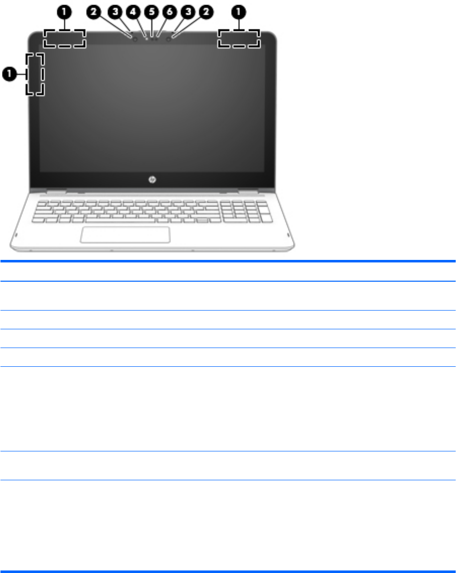
Display
Item Component Description
(1) WLAN antennas* Send and receive wireless signals to communicate
with WLANs.
(2) Infrared camera lights (2; select computer models only) The infrared camera is in use.
(3) Internal microphones (2) Record sound.
(4) Webcam light On: The webcam is in use.
(5) Webcam Records video and captures photographs. Some products
allow you to video conference and chat online using
streaming video.
To use a webcam (integrated camera):
▲Type camera in the taskbar search box, and then
select Camera.
(6) Infrared camera (select computer models only) Allows a facial recognition logon to Windows, instead of
a password.
*The antennas are not visible from the outside of the computer, and the antenna location may vary. For optimal transmission, keep
the areas immediately around the antennas free from obstructions.
For wireless regulatory notices, see the section of the Regulatory, Safety, and Environmental Notices that applies to your country
or region.
To access this guide:
▲Select the Start button, select All apps, select HP Help and Support, and then select HP Documentation.
Display 7
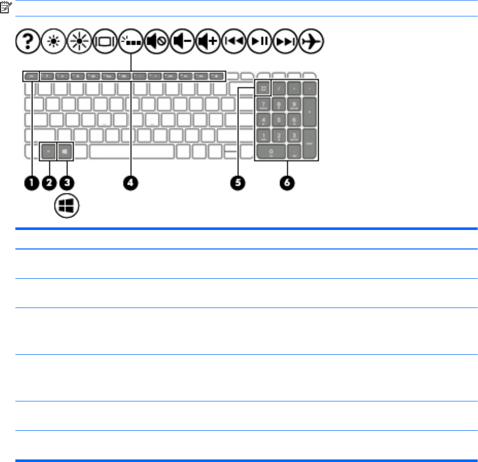
Keys
NOTE: Your computer may look slightly dierent from the illustration below.
Item Component Description
(1) esc key Displays system information when pressed in combination
with the fn key.
(2) fn key Displays system information when pressed in combination
with the esc key.
(3) Windows key Opens the Start menu.
NOTE: Pressing the Windows key again will close
the Start menu.
(4) Action keys Execute frequently used system functions.
NOTE: On select products, the f5 action key turns
the keyboard backlight feature o or on.
(5) num lock key (select products only) Alternates between the navigational and numeric functions
on the integrated numeric keypad.
(6) Integrated numeric keypad (select products only) When num lock is on, the keypad can be used like an external
numeric keypad.
8 Chapter 2 External component identication
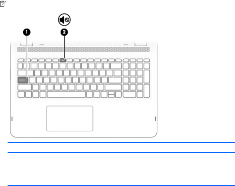
Lights
NOTE: Your computer may look slightly dierent from the illustration below.
Item Component Description
(1) Caps lock light On: Caps lock is on, which switches the key input to all
capital letters.
(2) Mute light ●Amber: Computer sound is o.
●O: Computer sound is on.
Lights 9
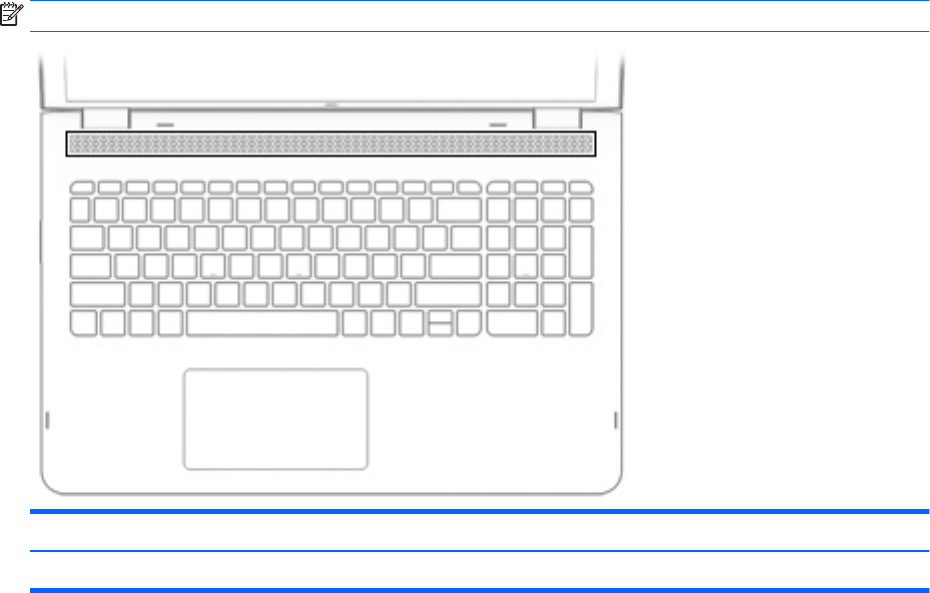
Speakers
NOTE: Your computer may look slightly dierent from the illustration below.
Component Description
Speakers Produce sound.
10 Chapter 2 External component identication
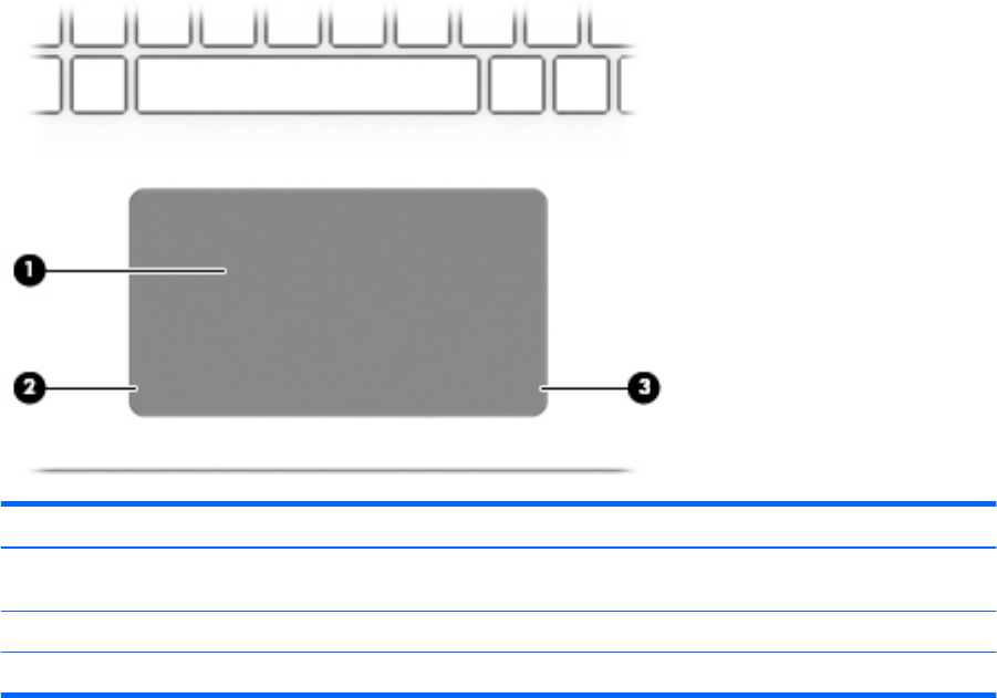
TouchPad
Item Component Description
(1) TouchPad zone Reads your nger gestures to move the pointer or activate
items on the screen.
(2) Left TouchPad button Functions like the left button on an external mouse.
(3) Right TouchPad button Functions like the right button on an external mouse.
TouchPad 11

Left side
Item Component Description
(1) Power button ●When the computer is o, press the button to turn on
the computer.
●When the computer is on, press the button briey to
initiate Sleep.
●When the computer is in the Sleep state, press
the button briey to exit Sleep.
●When the computer is in Hibernation, press the button
briey to exit Hibernation.
CAUTION: Pressing and holding down the power button
results in the loss of unsaved information.
If the computer has stopped responding and shutdown
procedures are ineective, press and hold the power button
down for at least 5 seconds to turn o the computer.
To learn more about your power settings, see your
power options.
▲Type power in the taskbar search box, and then select
Power and sleep settings.
‒ or –
Right-click the Start button, and then select
Power Options.
(2) Power light ●On: The computer is on.
●Blinking: The computer is in the Sleep state, a power-
saving state. The computer shuts o power to
the display and other unneeded components.
●O: The computer is o or in Hibernation. Hibernation
is a power-saving state that uses the least amount
of power.
(3) Security cable slot Attaches an optional security cable to the computer.
NOTE: The security cable is designed to act as a deterrent,
but it may not prevent the computer from being mishandled
or stolen.
(4) USB 2.0 port Connects an optional USB device, such as a keyboard, mouse,
external drive, printer, scanner, or USB hub.
(5) Audio-out (headphone)/Audio-in (microphone) combo jack Connects optional powered stereo speakers, headphones,
earbuds, a headset, or a television audio cable. Also connects
12 Chapter 2 External component identication

Item Component Description
(5) Audio-out (headphone)/Audio-in (microphone) combo jack
(continued)
an optional headset microphone. This jack does not support
optional standalone microphones.
WARNING! To reduce the risk of personal injury, adjust
the volume before putting on headphones, earbuds, or a
headset. For additional safety information, refer to
the Regulatory, Safety, and Environmental Notices.
To access this guide:
▲Select the Start button, select All apps, select HP Help
and Support, and then select HP Documentation.
NOTE: When a device is connected to the jack,
the computer speakers are disabled.
(6) Volume button Control speaker volume on the computer.
1. To increase speaker volume, press the back edge of
the button.
2. To decrease speaker volume, press the front edge of
the button.
(7) Drive light ●Blinking white: The hard drive is being accessed.
●Amber: HP 3D DriveGuard has temporarily parked
the hard drive.
NOTE: On select products, the drive light will always
remain o.
Left side 13

Right side
Item Component Description
(1) Memory card reader Reads optional memory cards that enable you to store,
manage, share, or access information.
To insert a card:
1. Hold the card label-side up, with connectors facing
the computer.
2. Insert the card into the memory card reader, and then
press in on the card until it is rmly seated.
To remove a card:
▲Press in on the card, and then remove it from
the memory card reader.
(2) USB Type-C port Connects an optional USB device with a Type-C connector.
(3) USB 3.0 charging (powered) port Connects an optional USB device, such as a keyboard, mouse,
external drive, printer, scanner, or USB hub. Standard USB
ports will not charge all USB devices or will charge using a
low current. Some USB devices require power and require
you to use a powered port.
NOTE: USB charging ports can also charge select models of
cell phones and MP3 players, even when the computer is o.
(4) HDMI port Connects an optional video or audio device, such as a high-
denition television, any compatible digital or audio
component, or a high-speed High-Denition Multimedia
Interface (HDMI) device.
(5) AC adapter and battery light ●White: The AC adapter is connected and the battery is
fully charged.
●Blinking white: The AC adapter is disconnected
and the battery has reached a low battery level.
●Amber: The AC adapter is connected and the battery
is charging.
●O: The battery is not charging.
(6) Power connector Connects an AC adapter.
14 Chapter 2 External component identication
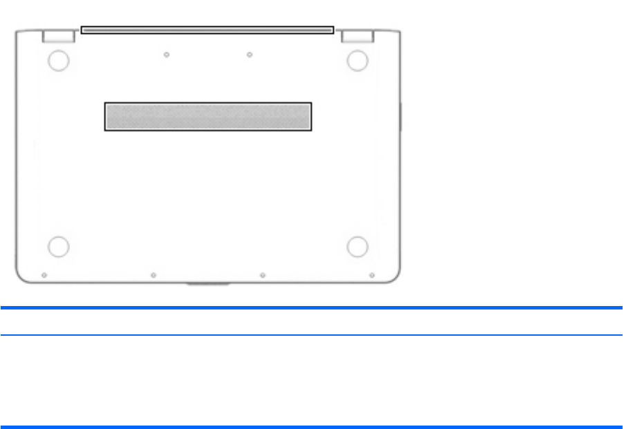
Bottom
Component Description
Vents (2) Enable airow to cool internal components.
NOTE: The computer fan starts up automatically to cool
internal components and prevent overheating. It is normal
for the internal fan to cycle on and o during routine
operation.
Bottom 15
3 Illustrated parts catalog
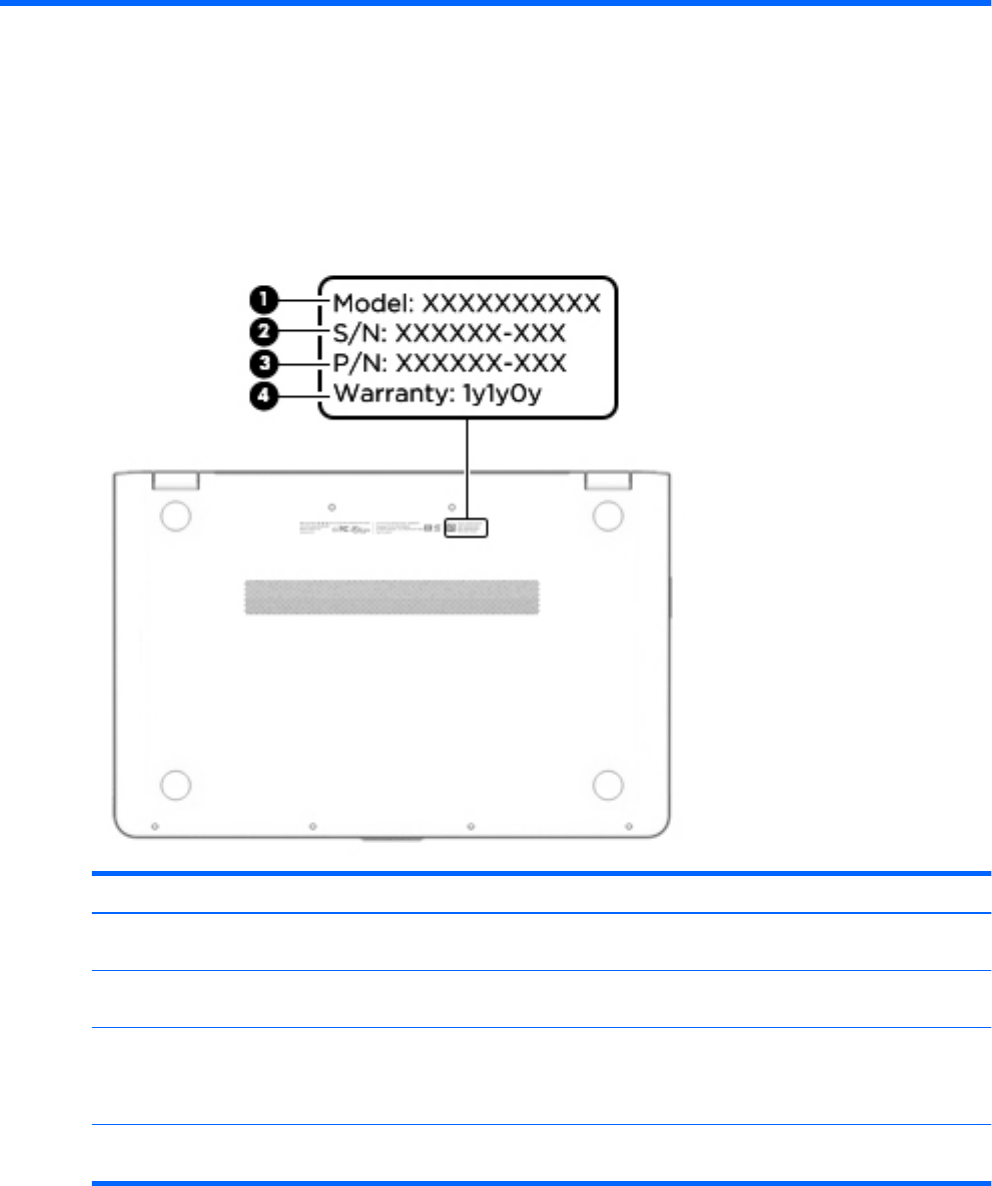
Service tag
When ordering parts or requesting information, provide the computer serial number and model number
provided on the service tag.
Item Description Function
(1) Model description This is the alphanumeric identier used to locate
documents, drivers, and support for the computer.
(2) Serial number (s/n) This is an alphanumeric identier that is unique to
each product.
(3) Part number/Product number (p/n) This number provides specic information about
the product's hardware components. The part number helps
a service technician to determine what components
and parts are needed.
(4) Warranty period This number describes the duration of the warranty period
for the computer.
16 Chapter 3 Illustrated parts catalog
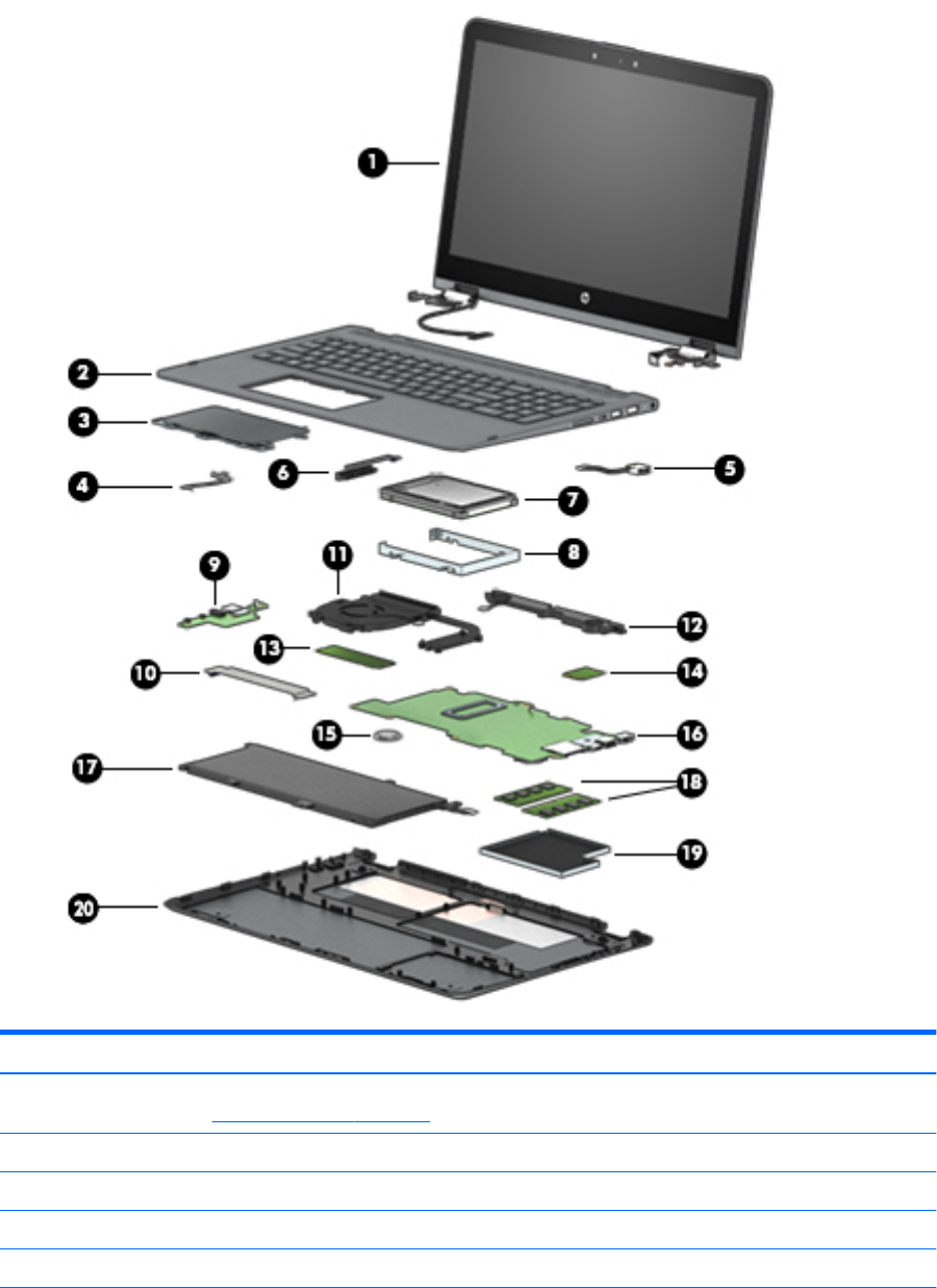
Computer major components
Item Component Spare part number
(1) Display assembly: The display assembly is spared at the subcomponent level only. For more display assembly spare part
information, see Display components on page 20.
(2) Keyboard/top cover (in natural silver nish; includes TouchPad and cable, backlight cable, and keyboard cable):
For use in Belgium 857283-A41
For use in Canada 857283-DB1
For use in the Czech Republic and Slovakia 857283-FL1
Computer major components 17

Item Component Spare part number
For use in Denmark, Finland, and Norway 857283-DH1
For use in France 857283-051
For use in Germany 857283-041
For use in Italy 857283-061
For use in Latin America 857283-161
For use in the Netherlands 857283-B31
For use in Russia 857283-251
For use in Saudi Arabia 857283-171
For use in Spain 857283-071
For use in Switzerland 857283-BG1
For use in Turkey 857283-141
For use in the United Kingdom 857283-031
For use in the United States 857283-001
(3) TouchPad (in natural silver nish; includes bracket) 858843-001
(4) TouchPad cable (includes double-sided adhesive) 856802-001
(5) Power connector cable 808155-011
(6) Hard drive cable (includes double-sided adhesive) 856788-001
(7) Hard drive:
NOTE: The hard drive spare part kit does not include the hard drive bracket, cable, or screws. The hard drive bracket
and screws are available using spare part number 856789-001. The hard drive cable is available using spare part number
856788-001.
2-TB, 5400-rpm, SATA, 9.5-mm hard drive 801808-005
1-TB, 7200-rpm, SATA, 9.5-mm hard drive 766644-005
1-TB, 5400-rpm, SATA, 8-GB hybrid, 9.5-mm hard drive 731999-005
(8) Hard drive bracket (includes screws) 856789-001
(9) Connector board (includes audio jack and USB port) 856808-001
(10) Connector board cable (includes double-sided adhesive) 856801-001
(11) Fan/heat sink assembly (includes replacement thermal material) 856277-001
(12) Speakers (includes subwoofer, cables, and three isolators) 856798-001
(13) Solid-state drive:
256-MB, M2.2280, solid-state drive supporting TLC for use on all computer models 847109-003
128-MB, M2.2280, SATA-3, solid-state drive for use only on computer models with model
number m6-aq1XX
827560-009
(14) Intel Dual Band Wireless-AC 7265 802.11 AC 2×2 WiFi + Bluetooth 4.2 Combo Adapter
(non vPRO)
793840-005
(15) RTC battery 616073-001
18 Chapter 3 Illustrated parts catalog

Item Component Spare part number
(16) System board (includes processor, a graphics subsystem with UMA memory, and replacement thermal material):
For use only on computer models with model number m6-aq1XX:
Equipped with an Intel CoreT i7-7500U 2.70-GHz (SC turbo up to 3.50-GHz) processor
(2133-MHz FSB, 4.0-MB L3 cache, dual core, 15 W) and the Windows 10 operating system
858871-601
Equipped with an Intel CoreT i7-7500U 2.70-GHz (SC turbo up to 3.50-GHz) processor
(2133-MHz FSB, 4.0-MB L3 cache, dual core, 15 W) and a non-Windows operating system
858871-001
Equipped with an Intel Core i5-7200U 2.50-GHz (SC turbo up to 3.10-GHz) processor (2133-
MHz FSB, 3.0-MB L3 cache, dual core, 15 W) and the Windows 10 operating system
858872-601
Equipped with an Intel Core i5-7200U 2.50-GHz (SC turbo up to 3.10-GHz) processor (2133-
MHz FSB, 3.0-MB L3 cache, dual core, 15 W) and a non-Windows operating system
858872-001
For use on all computer models:
Equipped with an Intel Core i7-6560U 2.20-GHz (SC turbo up to 3.20-GHz) processor (2133-
MHz FSB, 4.0-MB L3 cache, dual core, 15-W) and the Windows 10 Professional
operating system
856280-601
Equipped with an Intel Core i7-6560U 2.20-GHz (SC turbo up to 3.20-GHz) processor (2133-
MHz FSB, 4.0-MB L3 cache, dual core, 15-W) and a non-Windows operating system
856280-001
Equipped with an Intel Core i7-6500U 2.50-GHz (SC turbo up to 3.10-GHz) processor (2133-
MHz FSB, 4.0-MB L3 cache, dual core, 15-W) and the Windows 10 Professional
operating system
856278-601
Equipped with an Intel Core i7-6500U 2.50-GHz (SC turbo up to 3.10-GHz) processor (2133-
MHz FSB, 4.0-MB L3 cache, dual core, 15-W) and a non-Windows operating system
856278-001
Equipped with an Intel Core i5-6200U 2.30-GHz (SC turbo up to 2.80-GHz) processor (2133-
MHz FSB, 3.0-MB L3 cache, dual core, 15-W) and the Windows 10 Professional
operating system
856279-601
Equipped with an Intel Core i5-6200U 2.30-GHz (SC turbo up to 2.80-GHz) processor (2133-
MHz FSB, 3.0-MB L3 cache, dual core, 15-W) and a non-Windows operating system
856279-001
(17) 4-cell, 55-Wh, 3.62-Ah, Li-ion battery (includes cable) 844204-855
(18) Memory modules (2, 2133, 1.2-V, DDR4):
8-GB 820570-005
4-GB 820569-005
2-GB 851379-005
(19) Memory module shield 856815-001
(20) Bottom cover (in natural silver nish, includes front rubber feet, retention magnets,
shielding, and vents)
856800-001
Rubber Kit (not illustrated, includes bottom cover rubber feet) 856816-001
Computer major components 19
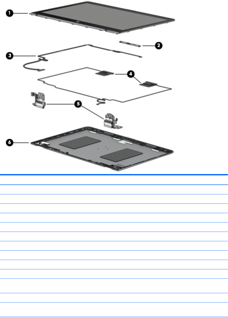
Display components
Item Component Spare part number
(1) Display panel assembly (includes bezel, panel, and TouchScreen board):
15.6-in, UHD, AG, USlim, IR 856814-001
15.6-in, UHD, AG, USlim 856812-001
15.6-in, FHD, BV, Slim, IR 856813-001
15.6-in, FHD, BV, Slim 856811-001
(2) Webcam/microphone module (includes double-sided adhesive):
3D webcam/microphone module 845631-001
Webcam/microphone module 833962-005
(3) Display panel cable (includes webcam/microphone module cable, adhesive support strip, and double-sided adhesive):
For use only on computer models equipped with a UHD display panel and a 3D webcam 856807-001
For use only on computer models equipped with a UHD display panel and a
non-3D webcam
856806-001
For use only on computer models equipped with an FHD display panel and a 3D webcam 856805-001
For use only on computer models equipped with an FHD display panel and a
non-3D webcam
856804-001
20 Chapter 3 Illustrated parts catalog

Item Component Spare part number
(4) G-sensor board (includes double-sided adhesive) 856809-001
(5) TouchScreen board cable (includes adhesive support strips and double-sided adhesive) 856803-001
(6) Display hinges (2) 856795-001
(7) Back cover (in natural silver nish; includes wireless antenna auxiliary and main cables
and transceivers)
856799-001
Miscellaneous parts
Component Spare part number
AC adapter:
45-W HP Smart AC adapter (non-PFC, 4.5-mm with mount) 854116-850
45-W HP Smart AC adapter (RC, 4.5-mm, slim) 741553-850
HP adapters:
HP duck head adapter (for use in the United States) 860828-001
HP HDMI-to-VGA adapter 701943-001
HP USB external DVD+/-RW DL SuperMulti Drive 747080-001
HP USB Type-C-to-USB 3.0 adapter 814618-001
HP USB-to-Gigabit RJ45 adapter 829941-001
Power cord (C5, 1.00-m):
For use in Denmark 213353-013
For use in Europe 213350-014
For use in Italy 213352-013
For use in North America 213349-015
For use in South Africa 361240-007
For use in Switzerland 213354-013
For use in the United Kingdom and Singapore 213351-013
Screw Kit 856797-001
Miscellaneous parts 21

4 Removal and replacement procedures
preliminary requirements
Tools required
You will need the following tools to complete the removal and replacement procedures:
●Case utility tool or similar plastic, at-edged tool
●Flat-bladed screwdriver
●Magnetic screwdriver
●Phillips P00, P0, and P1 screwdrivers
●Torx T4 screwdriver
Service considerations
The following sections include some of the considerations that you must keep in mind during disassembly
and assembly procedures.
NOTE: As you remove each subassembly from the computer, place the subassembly (and all accompanying
screws) away from the work area to prevent damage.
Plastic parts
CAUTION: Using excessive force during disassembly and reassembly can damage plastic parts. Use care
when handling the plastic
Cables and connectors
CAUTION: When servicing the computer, be sure that cables are placed in their proper locations during
the reassembly process. Improper cable placement can damage the computer.
Cables must be handled with extreme care to avoid damage. Apply only the tension required to unseat or seat
the cables during removal and insertion. Handle cables by the connector whenever possible. In all cases, avoid
bending, twisting, or tearing cables. Be sure that cables are routed in such a way that they cannot be caught
or snagged by parts being removed or replaced. Handle ex cables with extreme care; these cables
tear easily.
22 Chapter 4 Removal and replacement procedures preliminary requirements

Drive handling
CAUTION: Drives are fragile components that must be handled with care. To prevent damage to
the computer, damage to a drive, or loss of information, observe these precautions:
Before removing or inserting a hard drive, shut down the computer. If you are unsure whether the computer is
o or in Hibernation, turn the computer on, and then shut it down through the operating system.
Before handling a drive, be sure that you are discharged of static electricity. While handling a drive, avoid
touching the connector.
Before removing a diskette drive or optical drive, be sure that a diskette or disc is not in the drive and be sure
that the optical drive tray is closed.
Handle drives on surfaces covered with at least one inch of shock-proof foam.
Avoid dropping drives from any height onto any surface.
Avoid exposing an internal hard drive to products that have magnetic elds, such as monitors or speakers.
Avoid exposing an internal hard drive to products that have magnetic elds, such as monitors or speakers.
Avoid exposing a drive to temperature extremes or liquids.
If a drive must be mailed, place the drive in a bubble pack mailer or other suitable form of protective
packaging and label the package “FRAGILE.”
Service considerations 23

Grounding guidelines
Electrostatic discharge damage
Electronic components are sensitive to electrostatic discharge (ESD). Circuitry design and structure determine
the degree of sensitivity. Networks built into many integrated circuits provide some protection, but in many
cases, ESD contains enough power to alter device parameters or melt silicon junctions.
A discharge of static electricity from a nger or other conductor can destroy static-sensitive devices or
microcircuitry. Even if the spark is neither felt nor heard, damage may have occurred.
An electronic device exposed to ESD may not be aected at all and can work perfectly throughout a normal
cycle. Or the device may function normally for a while, then degrade in the internal layers, reducing its
life expectancy.
CAUTION: To prevent damage to the computer when you are removing or installing internal components,
observe these precautions:
Keep components in their electrostatic-safe containers until you are ready to install them.
Before touching an electronic component, discharge static electricity by using the guidelines described in
this section.
Avoid touching pins, leads, and circuitry. Handle electronic components as little as possible.
If you remove a component, place it in an electrostatic-safe container.
The following table shows how humidity aects the electrostatic voltage levels generated by
dierent activities.
CAUTION: A product can be degraded by as little as 700 V.
Typical electrostatic voltage levels
Relative humidity
Event 10% 40% 55%
Walking across carpet 35,000 V 15,000 V 7,500 V
Walking across vinyl oor 12,000 V 5,000 V 3,000 V
Motions of bench worker 6,000 V 800 V 400 V
Removing DIPS from plastic tube 2,000 V 700 V 400 V
Removing DIPS from vinyl tray 11,500 V 4,000 V 2,000 V
Removing DIPS from Styrofoam 14,500 V 5,000 V 3,500 V
Removing bubble pack from PCB 26,500 V 20,000 V 7,000 V
Packing PCBs in foam-lined box 21,000 V 11,000 V 5,000 V
24 Chapter 4 Removal and replacement procedures preliminary requirements
Packaging and transporting guidelines
Follow these grounding guidelines when packaging and transporting equipment:
●To avoid hand contact, transport products in static-safe tubes, bags, or boxes.
●Protect ESD-sensitive parts and assemblies with conductive or approved containers or packaging.
●Keep ESD-sensitive parts in their containers until the parts arrive at static-free workstations.
●Place items on a grounded surface before removing items from their containers.
●Always be properly grounded when touching a component or assembly.
●Store reusable ESD-sensitive parts from assemblies in protective packaging or nonconductive foam.
●Use transporters and conveyors made of antistatic belts and roller bushings. Be sure that mechanized
equipment used for moving materials is wired to ground and that proper materials are selected to avoid
static charging. When grounding is not possible, use an ionizer to dissipate electric charges.
Workstation guidelines
Follow these grounding workstation guidelines:
●Cover the workstation with approved static-shielding material.
●Use a wrist strap connected to a properly grounded work surface and use properly grounded tools
and equipment.
●Use conductive eld service tools, such as cutters, screwdrivers, and vacuums.
●When xtures must directly contact dissipative surfaces, use xtures made only of static safe materials.
●Keep the work area free of nonconductive materials, such as ordinary plastic assembly aids
and Styrofoam.
●Handle ESD-sensitive components, parts, and assemblies by the case or PCM laminate. Handle these
items only at static-free workstations.
●Avoid contact with pins, leads, or circuitry.
●Turn o power and input signals before inserting or removing connectors or test equipment.
Grounding guidelines 25

Equipment guidelines
Grounding equipment must include either a wrist strap or a foot strap at a grounded workstation.
●When seated, wear a wrist strap connected to a grounded system. Wrist straps are exible straps with a
minimum of one megohm ±10% resistance in the ground cords. To provide proper ground, wear a strap
snugly against the skin at all times. On grounded mats with banana-plug connectors, use alligator clips
to connect a wrist strap.
●When standing, use foot straps and a grounded oor mat. Foot straps (heel, toe, or boot straps) can be
used at standing workstations and are compatible with most types of shoes or boots. On conductive
oors or dissipative oor mats, use foot straps on both feet with a minimum of one megohm resistance
between the operator and ground. To be eective, the conductive must be worn in contact with the skin.
The following grounding equipment is recommended to prevent electrostatic damage:
●Antistatic tape
●Antistatic smocks, aprons, and sleeve protectors
●Conductive bins and other assembly or soldering aids
●Nonconductive foam
●Conductive computerop workstations with ground cords of one megohm resistance
●Static-dissipative tables or oor mats with hard ties to the ground
●Field service kits
●Static awareness labels
●Material-handling packages
●Nonconductive plastic bags, tubes, or boxes
●Metal tote boxes
●Electrostatic voltage levels and protective materials
The following table lists the shielding protection provided by antistatic bags and oor mats.
Material Use Voltage protection level
Antistatic plastics Bags 1,500 V
Carbon-loaded plastic Floor mats 7,500 V
Metallized laminate Floor mats 5,000 V
26 Chapter 4 Removal and replacement procedures preliminary requirements

5 Removal and replacement procedures
CAUTION: Components described in this chapter should only be accessed by an authorized service provider.
Accessing these parts can damage the computer or void the warranty.
Component replacement procedures
NOTE: Details about the computer, including model, serial number, product key, and length of warranty, are
on the service tag on the back of the computer. See Service tag on page 16 for details.
This chapter provides removal and replacement procedures.
There are as many as 56 screws that must be removed, replaced, and/or loosened when servicing
the computer. Make special note of each screw size and location during removal and replacement.
Bottom cover
Description Spare part number
Bottom cover (in natural silver nish; includes front rubber feet, retention magnets, shielding, and vents) 856800-001
Before disassembling the computer, follow these steps:
1. Turn o the computer. If you are unsure whether the computer is o or in Hibernation, turn
the computer on, and then shut it down through the operating system.
2. Disconnect the power from the computer by unplugging the power cord from the computer.
3. Disconnect all external devices from the computer.
Remove the bottom cover:
1. Close the computer.
2. Turn the computer upside down with the front toward you.
3. Remove the two rear rubber feet (1).
The rear rubber feet are included in the Rubber Kit, spare part number 856816-001.
Component replacement procedures 27
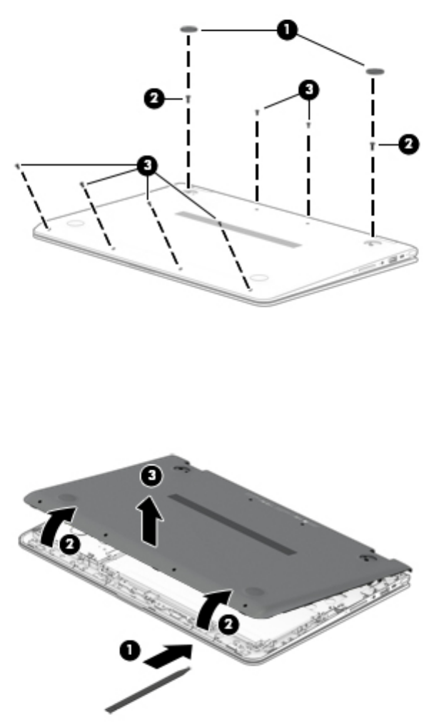
4. Remove the two Phillips M2.5×7.8 screws (2) and the six Phillips M2.0×5.2 screws (3) that secure
the bottom cover to the computer.
5. Insert a case utility tool (1) or similar plastic, at-edged tool between the bottom cover
and the computer near the display hinge area.
6. Release the bottom cover rear edge (2) and swing it up and back until it releases.
7. Remove the bottom cover (3).
Reverse this procedure to install the bottom cover.
28 Chapter 5 Removal and replacement procedures
Battery
Description Spare part number
4-cell, 55-Wh, 3.62-Ah, Li-ion battery (includes cable) 844204-855
Before removing the battery, follow these steps:
1. Turn o the computer. If you are unsure whether the computer is o or in Hibernation, turn
the computer on, and then shut it down through the operating system.
2. Disconnect the power from the computer by unplugging the power cord from the computer.
3. Disconnect all external devices from the computer.
4. Remove the battery (see Bottom cover on page 27).
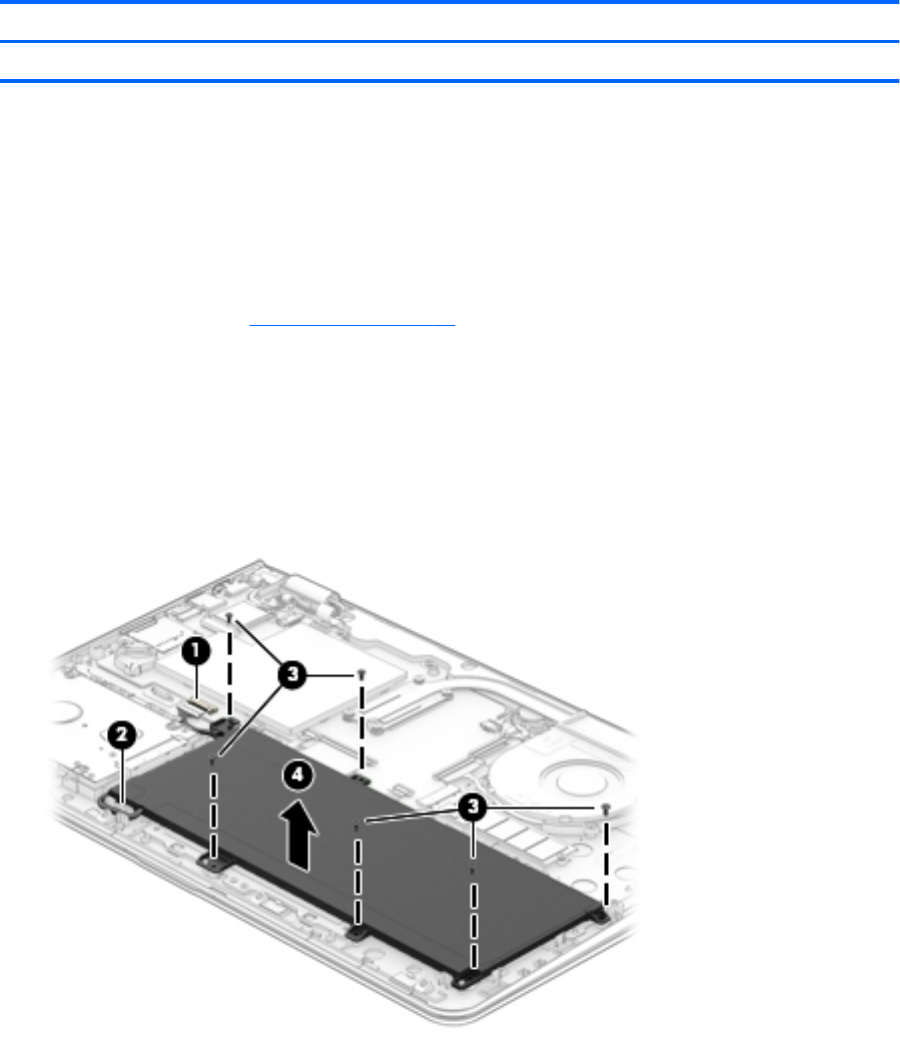
Remove the battery:
1. Disconnect the battery cable (1) from the system board.
2. Release the battery cable from the retention clip (2) built into the keyboard/top cover.
3. Remove the six Phillips M2.0×4.6 screws (3) that secure the battery to the keyboard/top cover.
4. Remove the battery (4).
Reverse this procedure to install the battery.
Component replacement procedures 29

Hard drive
NOTE: The hard drive spare part kit does not include the hard drive bracket, cable, or screws. The hard drive
bracket and screws are available using spare part number 856789-001. The hard drive cable is available using
spare part number 856788-001.
Description Spare part number
2-TB, 5400-rpm, SATA, 9.5-mm hard drive 801808-005
1-TB, 7200-rpm, SATA, 9.5-mm hard drive 766644-005
1-TB, 5400-rpm, SATA, 8-GB hybrid, 9.5-mm hard drive 731999-005
Before removing the hard drive, follow these steps:
1. Turn o the computer. If you are unsure whether the computer is o or in Hibernation, turn
the computer on, and then shut it down through the operating system.
2. Disconnect the power from the computer by unplugging the power cord from the computer.
3. Disconnect all external devices from the computer.
4. Remove the bottom cover (see Bottom cover on page 27).
5. Disconnect the battery cable from the system board (see Battery on page 29).
Remove the hard drive:
1. Release the zero insertion force (ZIF) connector (1) to which the hard drive cable is connected, and then
disconnect the hard drive cable from the system board.
2. Detach the hard drive cable (2) from the keyboard/top cover. (The hard drive cable is attached to
the keyboard/top cover with double-sided adhesive.)
3. Remove the four Phillips PM2.0×4.6 screws (3) that secure the hard drive to the keyboard/top cover.
30 Chapter 5 Removal and replacement procedures
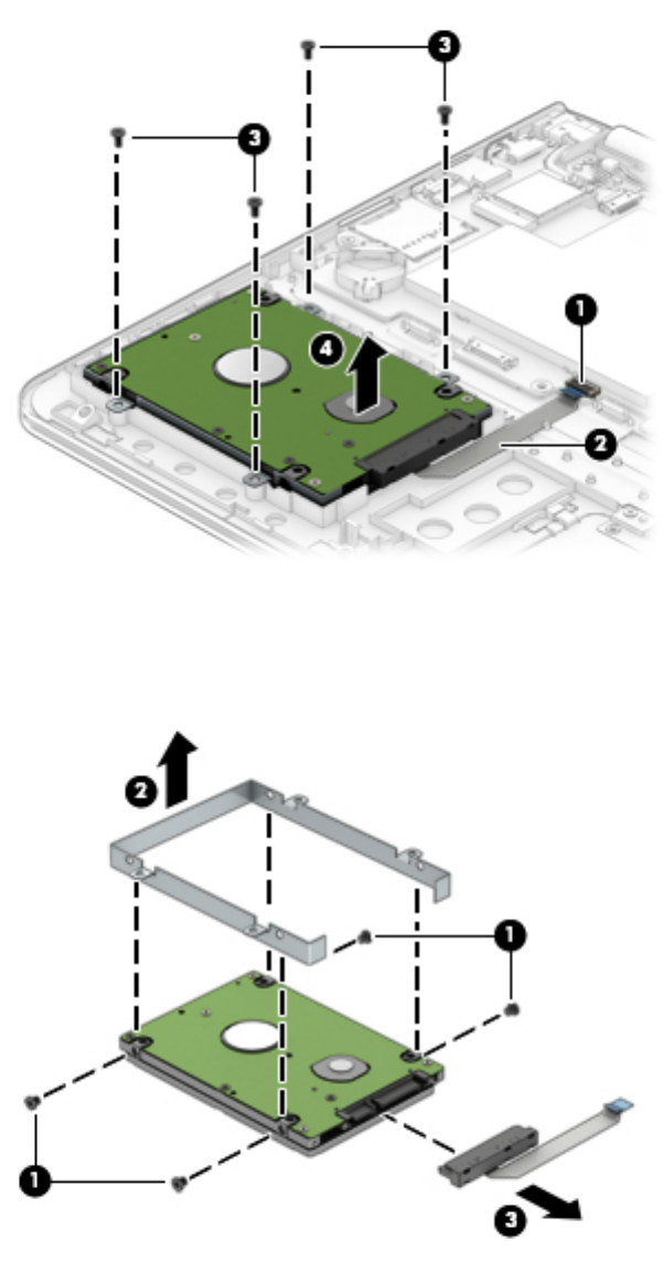
4. Remove the hard drive (4).
5. If it is necessary to replace the hard drive bracket, remove the four Phillips PM3.0×4.1 screws (1) that
secure the bracket to the hard drive, and then remove the hard drive bracket (2).
6. If it is necessary to replace the hard drive cable, slide the cable (3) o of the front end of the hard drive.
Reverse this procedure to reassemble and install the hard drive.
Component replacement procedures 31
RTC battery
Description Spare part number
RTC battery 616073-001
Before removing the TouchPad cable, follow these steps:
1. Turn o the computer. If you are unsure whether the computer is o or in Hibernation, turn
the computer on, and then shut it down through the operating system.
2. Disconnect the power from the computer by unplugging the power cord from the computer.
3. Disconnect all external devices from the computer.
4. Remove the bottom cover (see Bottom cover on page 27).
5. Remove the battery (see Battery on page 29).
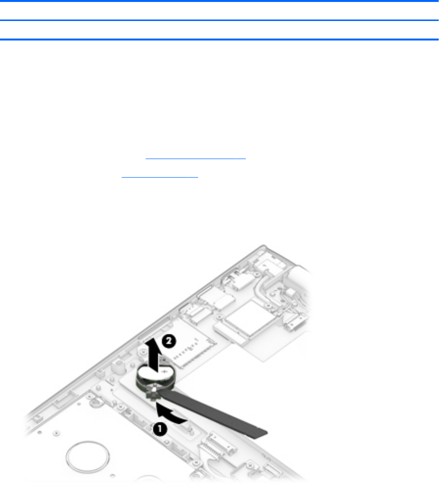
Remove the RTC battery:
▲Use a case utility tool (1) or similar plastic, at-edged tool to release the RTC battery (2) from its slot on
the system board.
Reverse this procedure to install the RTC battery. When installing the RTC battery, make sure the “+” sign is
facing up.
32 Chapter 5 Removal and replacement procedures
TouchPad cable
Description Spare part number
TouchPad cable (includes double-sided adhesive) 856802-001
Before removing the TouchPad cable, follow these steps:
1. Turn o the computer. If you are unsure whether the computer is o or in Hibernation, turn
the computer on, and then shut it down through the operating system.
2. Disconnect the power from the computer by unplugging the power cord from the computer.
3. Disconnect all external devices from the computer.
4. Remove the bottom cover (see Bottom cover on page 27).
5. Remove the battery (see Battery on page 29).
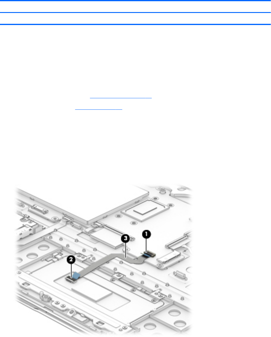
Remove the TouchPad cable:
1. Release the ZIF connector (1) to which the TouchPad cable is connected, and then disconnect
the TouchPad cable from the system board.
2. Release the ZIF connector (2) to which the TouchPad cable is connected, and then disconnect
the TouchPad cable from the TouchPad board.
3. Detach the TouchPad cable (3) from the keyboard/top cover. (The TouchPad cable is secured to
the keyboard/top cover with double-sided adhesive.)
4. Remove the TouchPad cable.
Reverse this procedure to install the TouchPad cable.
Component replacement procedures 33
TouchPad
Description Spare part number
TouchPad (in natural silver nish; includes bracket) 858843-001
Before removing the TouchPad, follow these steps:
1. Turn o the computer. If you are unsure whether the computer is o or in Hibernation, turn
the computer on, and then shut it down through the operating system.
2. Disconnect the power from the computer by unplugging the power cord from the computer.
3. Disconnect all external devices from the computer.
4. Remove the bottom cover (see Bottom cover on page 27).
5. Remove the battery (see Battery on page 29).
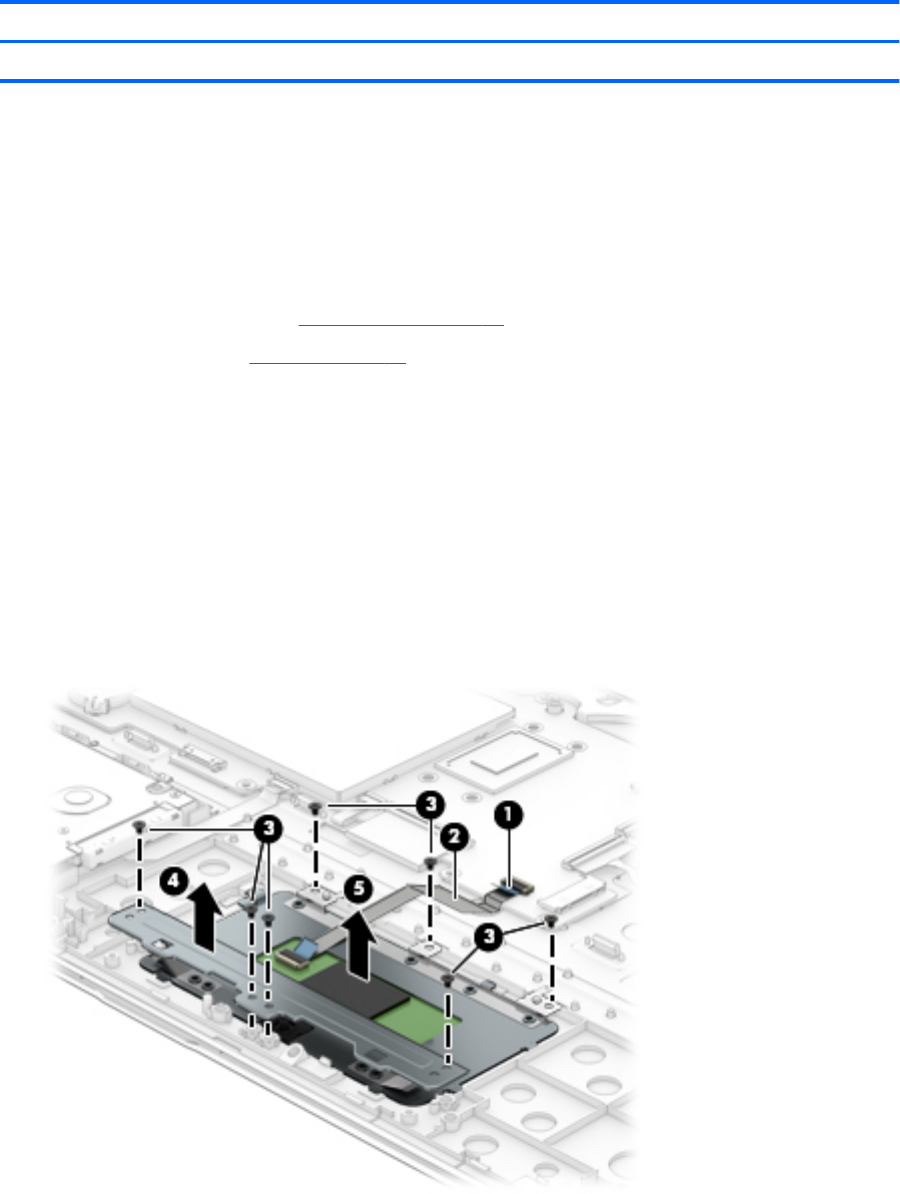
Remove the TouchPad:
1. Release the ZIF connector (1) to which the TouchPad cable is connected, and then disconnect
the TouchPad cable from the system board.
2. Detach the TouchPad cable (2) from the keyboard/top cover. (The TouchPad cable is secured to
the keyboard/top cover with double-sided adhesive.)
3. Remove the seven Phillips PM2.0×3.0 screws (3) that secure the TouchPad and TouchPad bracket to the
keyboard/top cover.
4. Remove the TouchPad bracket (4).
5. Remove the TouchPad (5).
Reverse this procedure to install the TouchPad.
34 Chapter 5 Removal and replacement procedures
Memory module
Description Spare part number
8-TB (2133, 1.2-V, DDR4) 820570-005
4-TB (2133, 1.2-V, DDR4) 820569-005
2-TB (2133, 1.2-V, DDR4) 851379-005
Before removing a memory module, follow these steps:
1. Turn o the computer. If you are unsure whether the computer is o or in Hibernation, turn
the computer on, and then shut it down through the operating system.
2. Disconnect the power from the computer by unplugging the power cord from the computer.
3. Disconnect all external devices from the computer.
4. Remove the bottom cover (see Bottom cover on page 27).
5. Disconnect the battery cable from the system board (see Battery on page 29).
Remove the memory module:
1. Remove the memory module shield that covers the memory module slots.
The memory module shield is available using spare part number 856815-001.
2. Spread the retaining tabs (1) on each side of the memory module slot to release the memory module.
(The memory module tilts up.)
Component replacement procedures 35
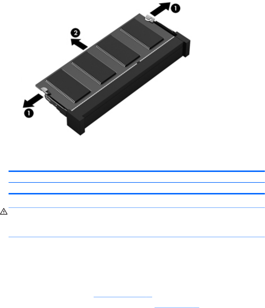
3. Remove the memory module (2) by pulling it away from the slot at an angle.
Reverse this procedure to install a memory module.
WLAN module
Description Spare part number
Intel Dual Band Wireless-AC 7265 802.11 AC 2×2 WiFi + Bluetooth 4.2 Combo Adapter (non vPRO) 793840-005
CAUTION: To prevent an unresponsive system, replace the wireless module only with a wireless module
authorized for use in the computer by the governmental agency that regulates wireless devices in your
country or region. If you replace the module and then receive a warning message, remove the module to
restore device functionality, and then contact technical support.
Before removing the WLAN module, follow these steps:
1. Turn o the computer. If you are unsure whether the computer is o or in Hibernation, turn
the computer on, and then shut it down through the operating system.
2. Disconnect the power from the computer by unplugging the power cord from the computer.
3. Disconnect all external devices from the computer.
4. Remove the bottom cover (see Bottom cover on page 27).
5. Disconnect the battery cable from the system board (see Battery on page 29).
Remove the WLAN module:
1. Disconnect the WLAN antenna cables (1) from the terminals on the WLAN module.
36 Chapter 5 Removal and replacement procedures
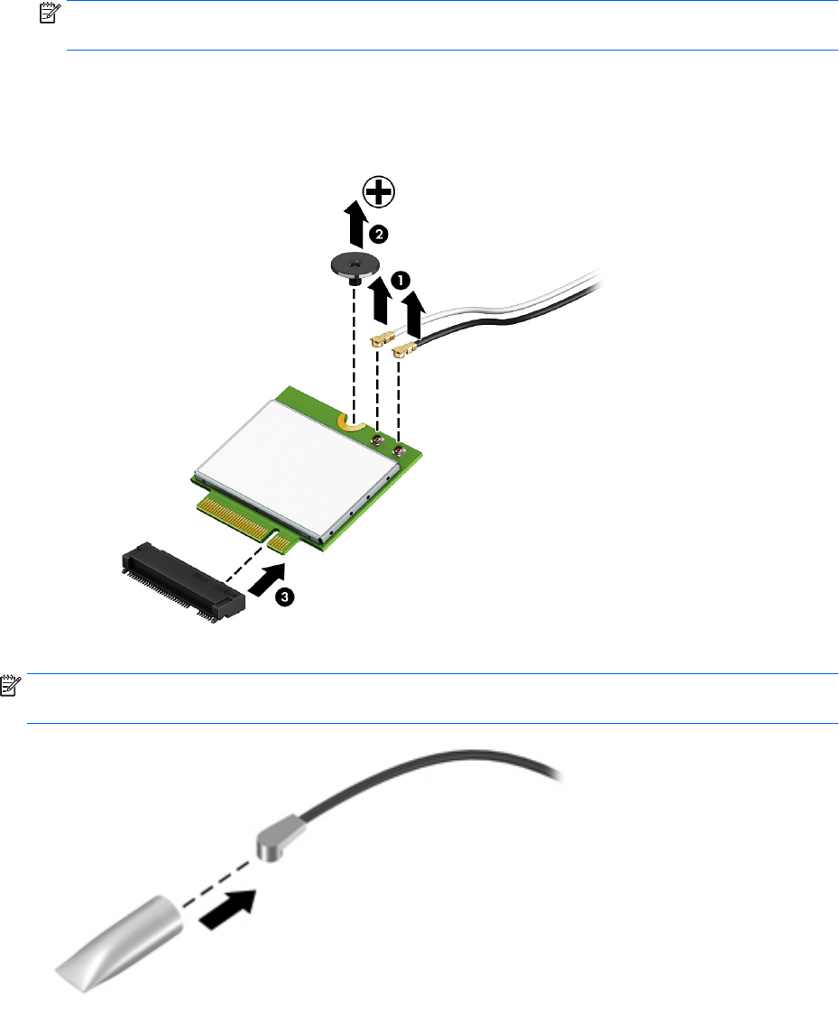
NOTE: The WLAN antenna cable labeled “1/MAIN” connects to the WLAN module “Main” terminal. The
WLAN antenna cable labeled “2/AUX” connects to the WLAN module “Aux” terminal.
2. Remove the Phillips PM2.0×3.8 screw (2) that secures the WLAN module to the computer. (The WLAN
module tilts up.)
3. Remove the WLAN module (3) by pulling the module away from the slot at an angle.
NOTE: If the WLAN antenna cables are not connected to the WLAN module terminal, the protective sleeves
should be installed on the antenna connectors, as shown in the following illustration.
Reverse this procedure to install the WLAN module.
Component replacement procedures 37
Solid-state drive
Description Spare part number
256-MB, M2.2280, solid-state drive supporting TLC for use on all computer models 847109-003
128-MB, M2.2280, SATA-3, solid-state drive for use only on computer models with model number m6-
aq1XX
827560-009
Before removing the solid-state drive, follow these steps:
1. Turn o the computer. If you are unsure whether the computer is o or in Hibernation, turn
the computer on, and then shut it down through the operating system.
2. Disconnect the power from the computer by unplugging the power cord from the computer.
3. Disconnect all external devices from the computer.
4. Remove the bottom cover (see Bottom cover on page 27).
5. Disconnect the battery cable from the system board (see Battery on page 29).
Remove the solid-state drive:
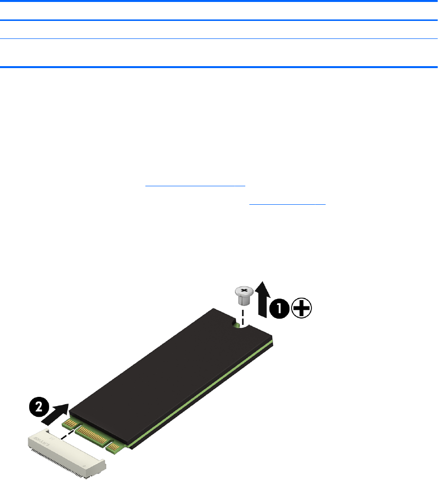
1. Remove the Phillips PM2.0×3.8 screw (1) that secures the solid-state drive to the computer. (The solid-
state drive tilts up.)
2. Remove the solid-state drive (2) by pulling the drive away from the slot at an angle.
Reverse this procedure to install the solid-state drive.
38 Chapter 5 Removal and replacement procedures
Fan/heat sink assembly
Description Spare part number
Fan/heat sink assembly (includes replacement thermal material) 856277-001
Before removing the fan/heat sink assembly, follow these steps:
1. Turn o the computer. If you are unsure whether the computer is o or in Hibernation, turn
the computer on, and then shut it down through the operating system.
2. Disconnect the power from the computer by unplugging the power cord from the computer.
3. Disconnect all external devices from the computer.
4. Remove the bottom cover (see Bottom cover on page 27).
5. Disconnect the battery cable from the system board (see Battery on page 29).
Remove the fan/heat sink assembly:
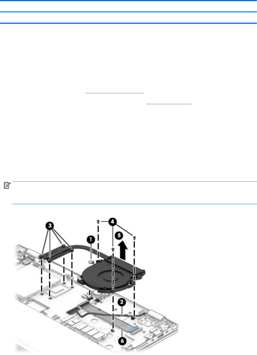
1. Disconnect the fan cable (1) from the system board.
2. Release the display panel cable (2) from the retention clips and channel built into the fan.
3. Loosen the four Phillips PM2.0×6.2 captive screws (3) that secure the fan/heat sink assembly to
the system board.
4. Remove the three Phillips PM2.0×4.6 screws (4) that secure the fan to the keyboard/top cover.
5. Remove the fan/heat sink assembly (5).
NOTE: It is necessary to detach the fan/heat sink assembly from the connector board cable (6) when
removing the fan/heat sink assembly. The fan/heat sink assembly is attached to the connector board
cable with double-sided adhesive.
Component replacement procedures 39
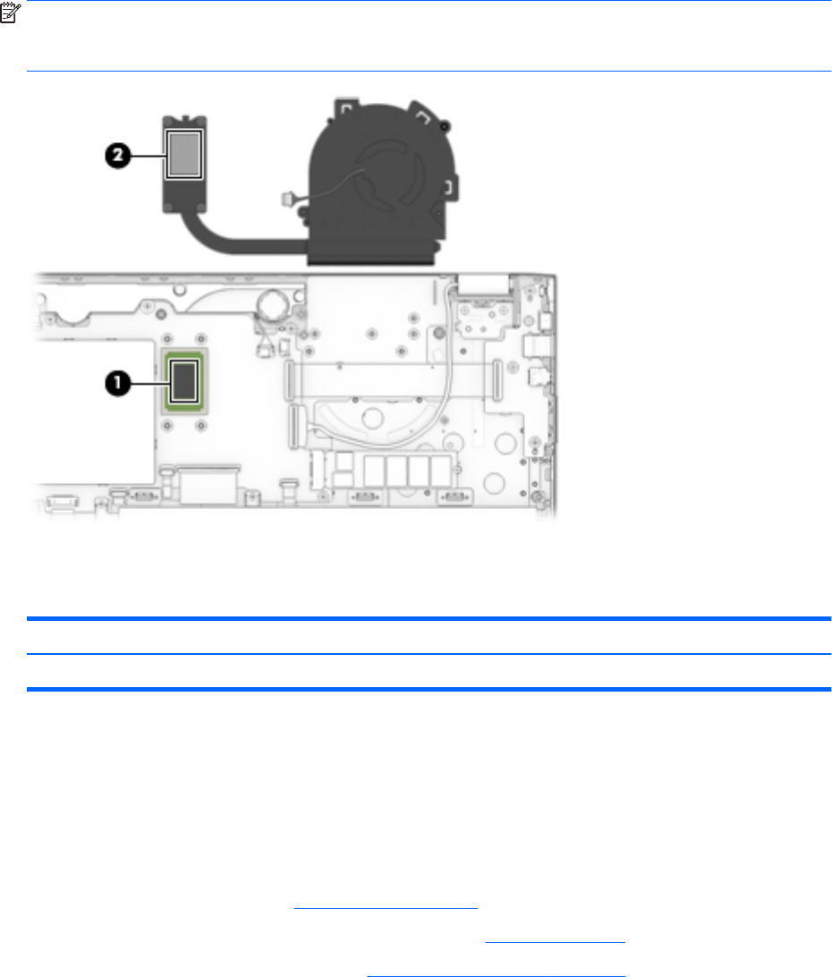
NOTE: The thermal material must be thoroughly cleaned from the surfaces of the fan/heat sink assembly
and the system board each time the fan/heat sink assembly is removed. Thermal paste is used on
the processor (1) and the fan/heat sink assembly section (2) that services it.
Reverse this procedure to install the fan/heat sink assembly.
Speakers
Description Spare part number
Speakers (includes subwoofer, cables, and three isolators) 856798-001
Before removing the speakers, follow these steps:
1. Turn o the computer. If you are unsure whether the computer is o or in Hibernation, turn
the computer on, and then shut it down through the operating system.
2. Disconnect the power from the computer by unplugging the power cord from the computer.
3. Disconnect all external devices from the computer.
4. Remove the bottom cover (see Bottom cover on page 27).
5. Disconnect the battery cable from the system board (see Battery on page 29).
6. Remove the fan/heat sink assembly (see Fan/heat sink assembly on page 39).
Remove the speakers:
1. Disconnect the speaker cable (1) from the system board.
2. Remove the three Phillips PM2.0×5.6 shoulder screws (2) that secure the speakers to the keyboard/
top cover.
40 Chapter 5 Removal and replacement procedures
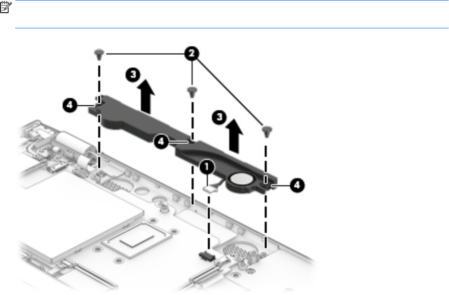
3. Remove the speakers (3).
NOTE: When removing the speakers, make note of the location of the three rubber isolators (4).
Failure to properly install or damage to these isolators can result in degraded speaker performance.
Reverse this procedure to install the speakers.
Component replacement procedures 41
Connector board
NOTE: The connector board spare part kit does not include the connector board cable. The connector board
cable is available using spare part number 856801-001.
Description Spare part number
Connector board (includes audio jack and USB port) 856808-001
Before removing the connector board, follow these steps:
1. Turn o the computer. If you are unsure whether the computer is o or in Hibernation, turn
the computer on, and then shut it down through the operating system.
2. Disconnect the power from the computer by unplugging the power cord from the computer.
3. Disconnect all external devices from the computer.
4. Remove the bottom cover (see Bottom cover on page 27).
5. Disconnect the battery cable from the system board (see Battery on page 29).
6. Remove the fan/heat sink assembly (see Fan/heat sink assembly on page 39).
Remove the connector board:
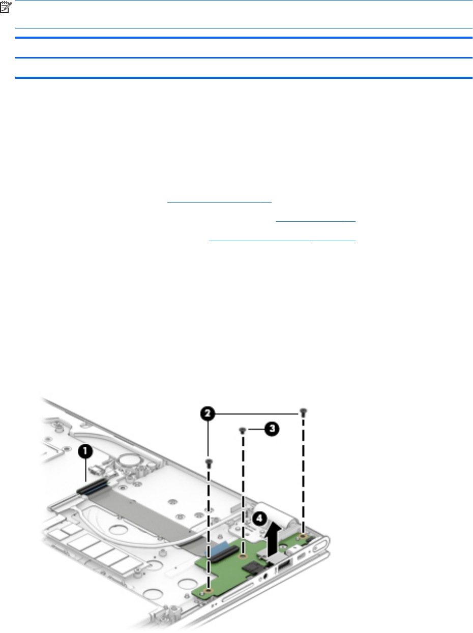
1. Release the ZIF connector (1) to which the connector board cable is connected, and then disconnect
the connector board cable from the system board.
2. Detach the connector board cable (2) from the keyboard/top cover. (The connector board cable is
attached to the keyboard/top cover with double-sided adhesive.)
3. Remove the two Phillips PM2.0×4.6 screws (3) and the Phillips PM2.0×3.3 screw (4) that secure
the connector board to the keyboard/top cover.
4. Remove the connector board (5).
42 Chapter 5 Removal and replacement procedures

Reverse this procedure to install the connector board.
System board
NOTE: The system board spare part kit includes the processor, a graphics subsystem with UMA memory,
and replacement thermal material.
Description Spare part number
For use only on computer models with model number m6-aq1XX:
Equipped with an Intel CoreT i7-7500U 2.70-GHz (SC turbo up to 3.50-GHz) processor (2133-MHz FSB,
4.0-MB L3 cache, dual core, 15 W) and the Windows 10 operating system
858871-601
Equipped with an Intel CoreT i7-7500U 2.70-GHz (SC turbo up to 3.50-GHz) processor (2133-MHz FSB,
4.0-MB L3 cache, dual core, 15 W) and a non-Windows operating system
858871-001
Equipped with an Intel Core i5-7200U 2.50-GHz (SC turbo up to 3.10-GHz) processor (2133-MHz FSB,
3.0-MB L3 cache, dual core, 15 W) and the Windows 10 operating system
858872-601
Equipped with an Intel Core i5-7200U 2.50-GHz (SC turbo up to 3.10-GHz) processor (2133-MHz FSB,
3.0-MB L3 cache, dual core, 15 W) and a non-Windows operating system
858872-001
For use on all computer models:
Equipped with an Intel Core i7-6560U 2.20-GHz (SC turbo up to 3.20-GHz) processor (2133-MHz FSB,
4.0-MB L3 cache, dual core, 15-W), a graphics subsystem with UMA memory, and the Windows 10
Professional operating system
856280-601
Equipped with an Intel Core i7-6560U 2.20-GHz (SC turbo up to 3.20-GHz) processor (2133-MHz FSB,
4.0-MB L3 cache, dual core, 15-W), a graphics subsystem with UMA memory, and a non-Windows
operating system
856280-001
Equipped with an Intel Core i7-6500U 2.50-GHz (SC turbo up to 3.10-GHz) processor (2133-MHz FSB,
4.0-MB L3 cache, dual core, 15-W), a graphics subsystem with UMA memory, and the Windows 10
Professional operating system
856278-601
Equipped with an Intel Core i7-6500U 2.50-GHz (SC turbo up to 3.10-GHz) processor (2133-MHz FSB,
4.0-MB L3 cache, dual core, 15-W), a graphics subsystem with UMA memory, and a non-Windows
operating system
856278-001
Equipped with an Intel Core i5-6200U 2.30-GHz (SC turbo up to 2.80-GHz) processor (2133-MHz FSB,
3.0-MB L3 cache, dual core, 15-W), a graphics subsystem with UMA memory, and the Windows 10
Professional operating system
856279-601
Equipped with an Intel Core i5-6200U 2.30-GHz (SC turbo up to 2.80-GHz) processor (2133-MHz FSB,
3.0-MB L3 cache, dual core, 15-W), a graphics subsystem with UMA memory, and a non-Windows
operating system
856279-001
Before removing the system board, follow these steps:
1. Turn o the computer. If you are unsure whether the computer is o or in Hibernation, turn
the computer on, and then shut it down through the operating system.
2. Disconnect the power from the computer by unplugging the power cord from the computer.
3. Disconnect all external devices from the computer.
4. Remove the bottom cover (see Bottom cover on page 27).
5. Remove the battery (see Battery on page 29).
6. Remove the fan/heat sink assembly (see Fan/heat sink assembly on page 39).
Component replacement procedures 43

NOTE: When replacing the system board, be sure that the following components are removed from
the defective system board and installed on the replacement system board:
●RTC battery (see Bottom cover on page 27)
●Memory module shield and memory module (see Memory module on page 35)
●WLAN module (see WLAN module on page 36)
Remove the system board:
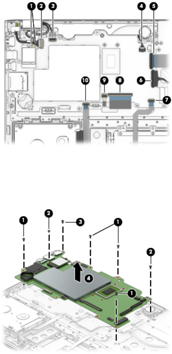
1. Disconnect the following cables from the system board:
(1) WLAN module antenna cables
NOTE: The WLAN “Main/#1”antenna cable is connected to the WLAN module “Main” terminal. The
WLAN “Aux/#2”antenna cable is connected to the WLAN module “Aux” terminal.
(2) Power connector cable
(3) TouchScreen board ZIF connector cable
(4) Speaker cable
(5) Connector board ZIF connector cable
(6) Display panel ZIF connector cable
(7) TouchPad board ZIF connector cable
(8) Keyboard ZIF connector cable
(9) Backlight ZIF connector cable
(10) Hard drive ZIF connector cable
44 Chapter 5 Removal and replacement procedures
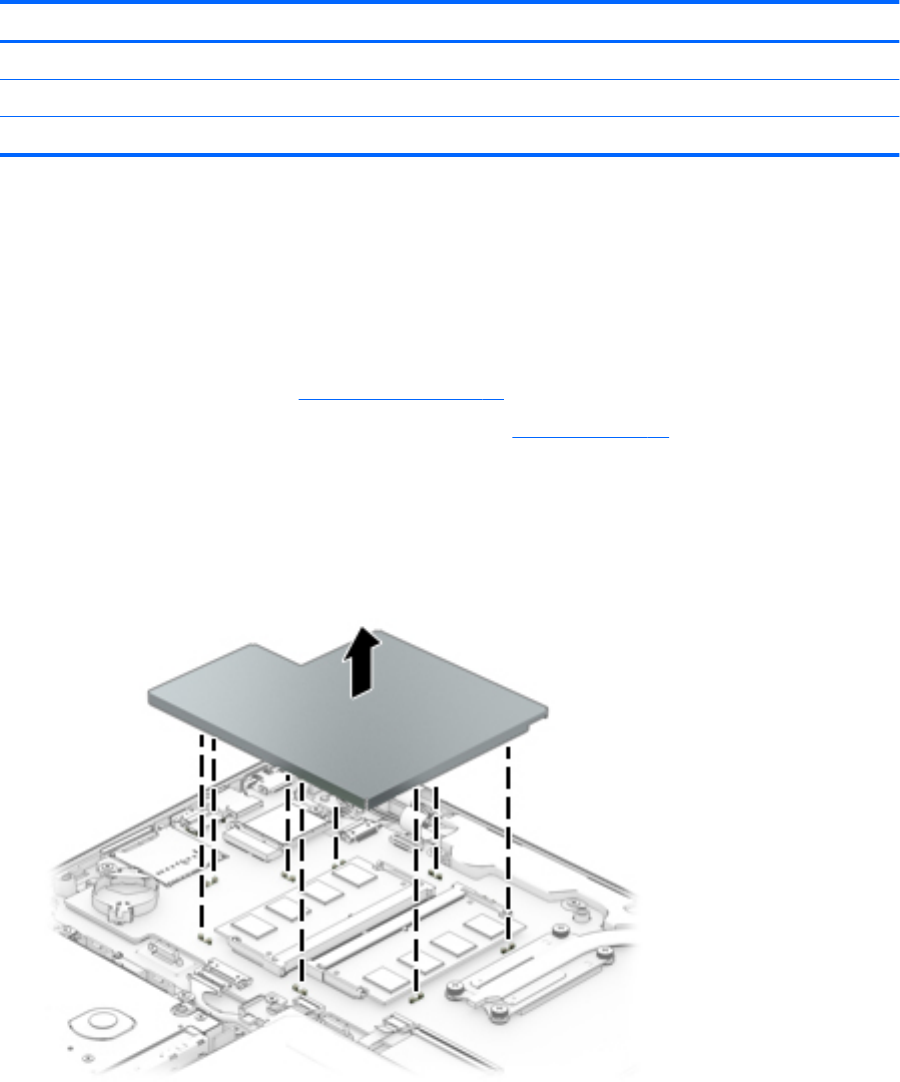
2. Remove the following screws that secure the system board to the keyboard/top cover:
(1) Four Phillips PM2.0×4.6 screws
(2) Two Phillips PM2.0×3.3 screws
(3) One Phillips PM2.5×4.5 screw
3. Remove the system board (4).
Reverse this procedure to install the system board.
Component replacement procedures 45
Display assembly
NOTE: The display assembly is spared at the subcomponent level only. For display assembly spare part
information, see the individual removal subsections.
Before removing the display assembly, follow these steps:
1. Turn o the computer. If you are unsure whether the computer is o or in Hibernation, turn
the computer on, and then shut it down through the operating system.
2. Disconnect the power from the computer by unplugging the power cord from the computer.
3. Disconnect all external devices from the computer.
4. Remove the bottom cover (see Bottom cover on page 27), and then removed the following components:
a. Battery (see Battery on page 29).
b. Fan/heat sink assembly (see Fan/heat sink assembly on page 39).
c. System board (see System board on page 43).
Remove the display assembly:
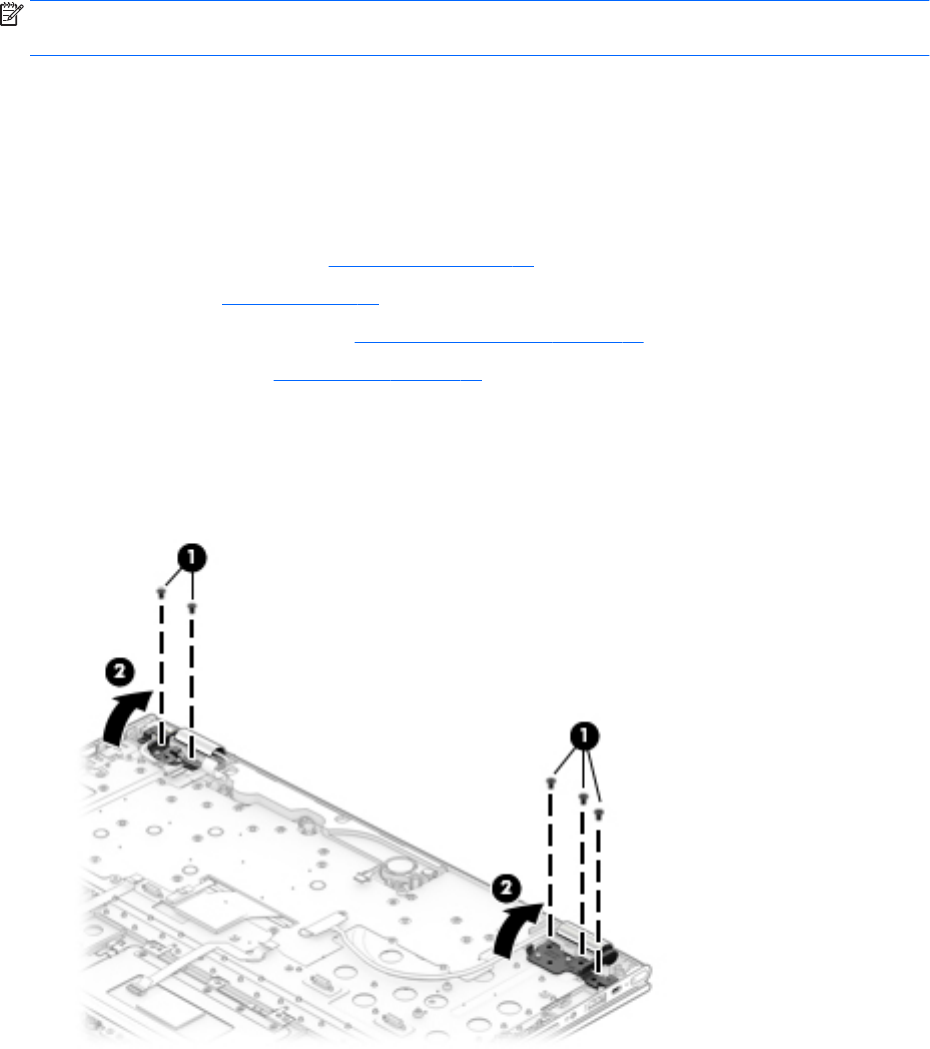
1. Remove the ve Phillips PM2.5×4.5 screws (1) that secure the display assembly to the keyboard/
top cover.
2. Release the display hinges (2) by swinging them up and back.
3. Lift the front edge of the keyboard/top cover (1) until it rests at an angle.
46 Chapter 5 Removal and replacement procedures
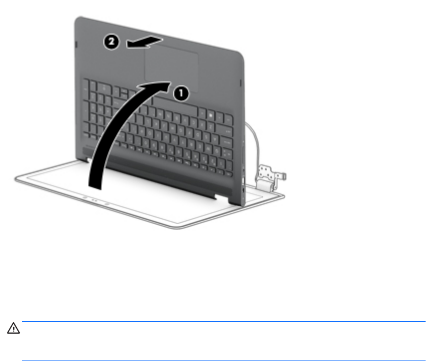
4. Slide the keyboard/top cover (2) forward and separate it from the display assembly.
5. If it is necessary to replace the display panel assembly:
a. Use a case utility tool or similar plastic, at-edged tool to separate the bottom edge (1) of
the display panel assembly from the display back cover.
b. Separate the top edge (2) of the display panel assembly from the display back cover.
CAUTION: Before turning the display panel assembly upside down, make sure the work surface is
clear of tools, screws, and any other foreign objects. Failure to follow this caution can result in
damage to the display panel assembly.
Component replacement procedures 47
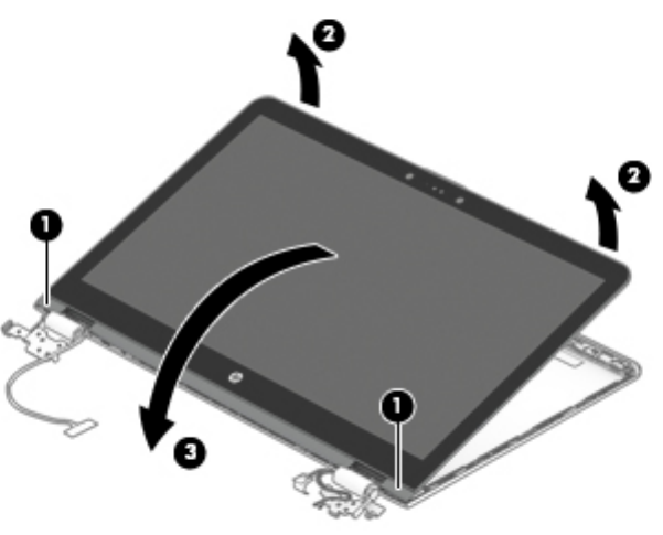
c. Swing the top edge (3) of the display panel assembly up and forward until the display panel
assembly rests upside down in front of the display back cover.
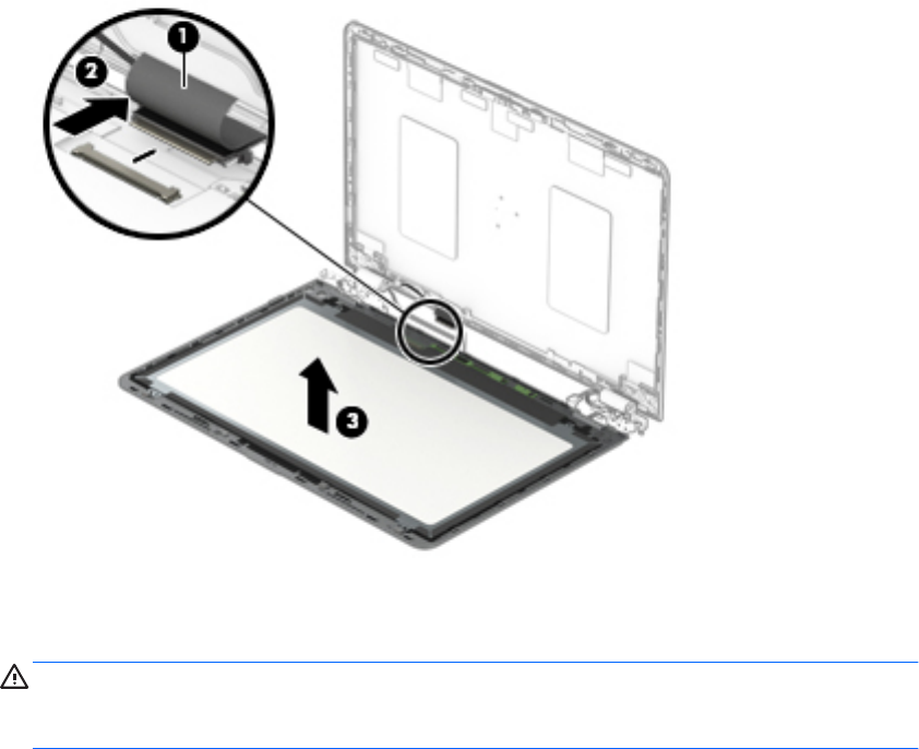
d. Release the adhesive support strip (1) that secures the display panel cable connector to
the display panel.
e. Disconnect the display panel cable (2) from the display panel.
f. Remove the display panel assembly (3).
The display panel assembly is available using the following spare part numbers:
●856814-001 – 15.6-in, UHD, AG, USlim, IR
●856812-001 – 15.6-in, UHD, AG, USlim
●856813-001 – 15.6-in, FHD, BV, Slim, IR
●856811-001 – 15.6-in, FHD, BV, Slim
48 Chapter 5 Removal and replacement procedures
6. If it is necessary to replace the TouchScreen board cable:
a. Remove the display panel assembly.
CAUTION: Before turning the display panel assembly upside down, make sure the work surface is
clear of tools, screws, and any other foreign objects. Failure to follow this caution can result in
damage to the display panel assembly.
b. Turn the display panel assembly upside down with the bottom edge toward you.
c. Release the adhesive support strip (1) that secures the TouchScreen board cable to the ZIF
connector on the TouchScreen board.
d. Release the ZIF connector (2) to which the TouchScreen board cable is connected, and then
disconnect the TouchScreen board cable from the TouchScreen board.
e. Remove the tape (3) that secures the TouchScreen board cable to the display back cover.
f. Release the adhesive support strip (4) that secures the TouchScreen board cable to the ZIF
connector on the G-sensor board.
g. Release the ZIF connector (5) to which the TouchScreen board cable is connected, and then
disconnect the TouchScreen board cable from the G-sensor board.
Component replacement procedures 49
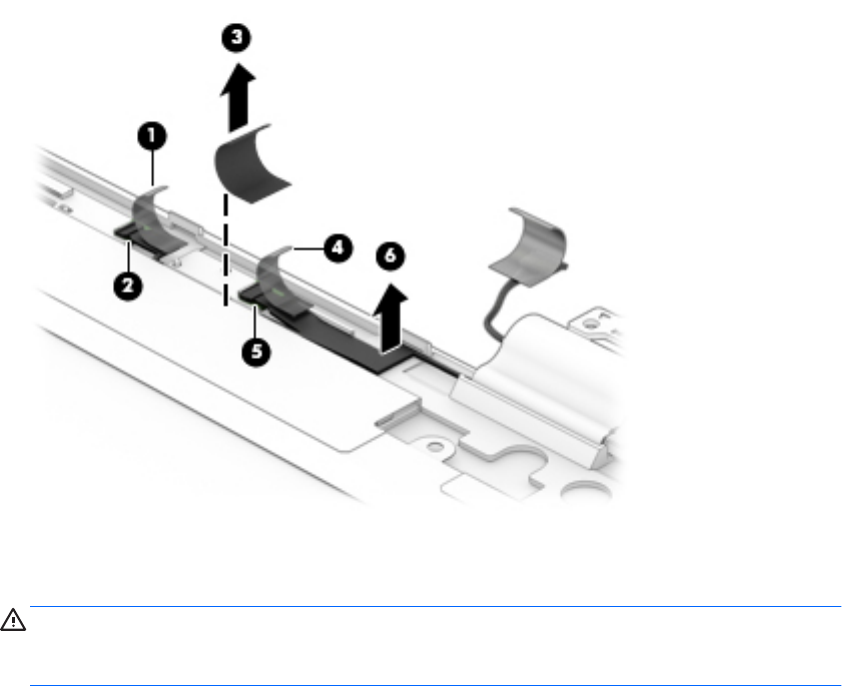
h. Remove the TouchScreen board cable (6).
The TouchScreen board cable is available using spare part number 856803-001.
7. If it is necessary to replace the G-sensor board:
a. Remove the display panel assembly.
CAUTION: Before turning the display panel assembly upside down, make sure the work surface is
clear of tools, screws, and any other foreign objects. Failure to follow this caution can result in
damage to the display panel assembly.
b. Turn the display panel assembly upside down with the bottom edge toward you.
c. Detach the adhesive support strip (1) that secures the TouchScreen board cable to the ZIF
connector on the G-sensor board.
d. Release the ZIF connector (2) to which the TouchScreen board cable is connected, and then
disconnect the TouchScreen board cable from the G-sensor board.
50 Chapter 5 Removal and replacement procedures
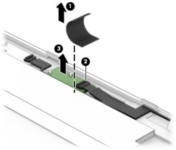
e. Detach the G-sensor board (3) from the display back cover. The G-sensor board is secured to
the display back cover with double-sided adhesive.)
f. Remove the G-sensor board.
The G-sensor board is available using spare part number 856809-001.
8. If it is necessary to replace the webcam/microphone module:
a. Remove the display panel assembly.
b. Detach the webcam/microphone module (1) from the display back cover. The webcam/microphone
module is secured to the display back cover with double-sided adhesive.)
c. Disconnect the webcam/microphone module cable (2) from the webcam/microphone module.
Component replacement procedures 51
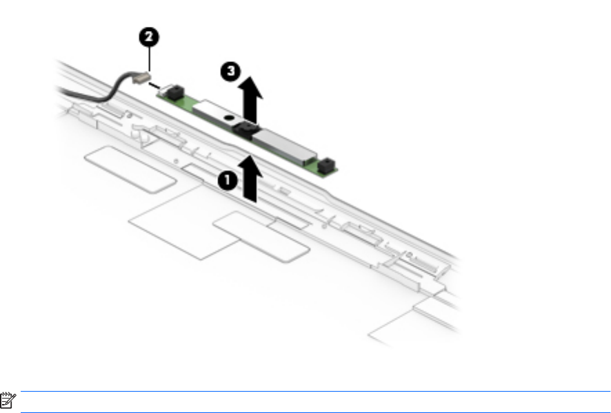
d. Remove the webcam/microphone module (3).
The webcam/microphone module is available using spare part numbers 845361-001 (3D webcam/
microphone module) and 833962-005 (non-3D webcam/microphone module).
9. If it is necessary to replace the display panel cable:
NOTE: The display panel cable includes the webcam/microphone module cable.
a. Remove the display panel assembly.
b. Disconnect the webcam/microphone module cable (1) from the webcam/microphone module.
c. Release the pieces of tape (2) that secure the display panel cable to the display back cover.
d. Release the grounding foil (3) that secures the display panel cable to the display back cover.
e. Release the display panel cable from the routing clips (4) and channels built into the top, left,
and bottom edges of the display back cover.
f. Remove the display panel cable (5).
The display panel cable is available using the following spare part numbers:
●856807-001 – For use only on computer models equipped with a UHD display panel and a 3D
webcam
●856806-001 – For use only on computer models equipped with a UHD display panel and a
non-3D webcam
●856805-001 – For use only on computer models equipped with an FHD display panel and a 3D
webcam
●856804-001 – For use only on computer models equipped with an FHD display panel and a
non-3D webcam
52 Chapter 5 Removal and replacement procedures
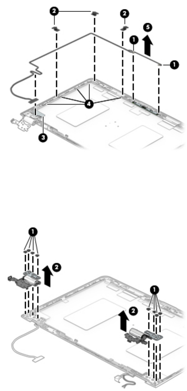
10. If it is necessary to replace the display hinges:
a. Remove the display panel assembly.
b. Remove the eight Phillips PM2.5×2.9 broadhead screws (1) that secure the display hinges to
the display back cover.
c. Remove the display hinges (2).
The display hinges are available using spare part number 856795-001.
Reverse this procedure to reassemble and install the display assembly.
Component replacement procedures 53
Power connector cable
Description Spare part number
Power connector cable 808155-011
Before removing the power connector cable, follow these steps:
1. Turn o the computer. If you are unsure whether the computer is o or in Hibernation, turn
the computer on, and then shut it down through the operating system.
2. Disconnect the power from the computer by unplugging the power cord from the computer.
3. Disconnect all external devices from the computer.
4. Remove the bottom cover (see Bottom cover on page 27), and then removed the following components:
a. Battery (see Battery on page 29).
b. Fan/heat sink assembly (see Fan/heat sink assembly on page 39).
c. System board (see System board on page 43).
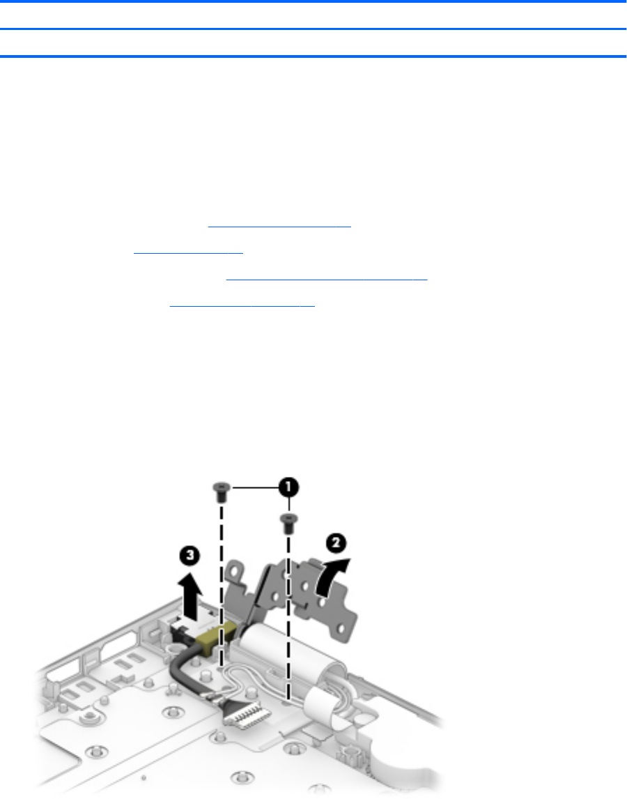
Remove the power connector cable:
1. Remove the two Phillips PM2.5×4.5 screws (1) that secure the left display hinge to the keyboard/
top cover.
2. Release the left display hinge (2) by swinging it up and back.
3. Remove the power connector cable (3).
Reverse this procedure to install the power connector cable.
54 Chapter 5 Removal and replacement procedures

6 Using Setup Utility (BIOS)
Setup Utility, or Basic Input/Output System (BIOS), controls communication between all the input and output
devices on the system (such as disk drives, display, keyboard, mouse, and printer). Setup Utility (BIOS)
includes settings for the types of devices installed, the startup sequence of the computer, and the amount of
system and extended memory.
NOTE: To start Setup Utility on convertible computers, your computer must be in notebook mode and you
must use the keyboard attached to your notebook.
Starting Setup Utility (BIOS)
CAUTION: Use extreme care when making changes in Setup Utility (BIOS). Errors can prevent the computer
from operating properly.
▲Turn on or restart the computer, quickly press esc, and then press f10.
Updating Setup Utility (BIOS)
Updated versions of Setup Utility (BIOS) may be available on the HP website.
Most BIOS updates on the HP website are packaged in compressed les called SoftPaqs.
Some download packages contain a le named Readme.txt, which contains information regarding installing
and troubleshooting the le.
Determining the BIOS version
To decide whether you need to update Setup Utility (BIOS), rst determine the BIOS version on your computer.
To reveal the BIOS version information (also known as ROM date and System BIOS), use one of these options.
●HP Support Assistant
1. Type support in the taskbar search box, and then select the HP Support Assistant app.
– or –
Click the question mark icon in the taskbar.
2. Select My PC, and then select Specications.
●Setup Utility (BIOS)
1. Start Setup Utility (BIOS) (see Starting Setup Utility (BIOS) on page 55).
2. Select Main, select System Information, and then make note of the BIOS version.
3. Select Exit, select No, and then follow the on-screen instructions.
To check for later BIOS versions, see Downloading a BIOS update on page 56.
Starting Setup Utility (BIOS) 55

Downloading a BIOS update
CAUTION: To reduce the risk of damage to the computer or an unsuccessful installation, download and
install a BIOS update only when the computer is connected to reliable external power using the AC adapter. Do
not download or install a BIOS update while the computer is running on battery power, docked in an optional
docking device, or connected to an optional power source. During the download and installation, follow these
instructions:
●Do not disconnect power from the computer by unplugging the power cord from the AC outlet.
●Do not shut down the computer or initiate Sleep.
●Do not insert, remove, connect, or disconnect any device, cable, or cord.
NOTE: If your computer is connected to a network, consult the network administrator before installing any
software updates, especially system BIOS updates.
1. Type support in the taskbar search box, and then select the HP Support Assistant app.
– or –
Click the question mark icon in the taskbar.
2. Click Updates, and then click Check for updates and messages.
3. Follow the on-screen instructions.
4. At the download area, follow these steps:
a. Identify the most recent BIOS update and compare it to the BIOS version currently installed on your
computer. If the update is more recent than your BIOS version, make a note of the date, name, or
other identier. You may need this information to locate the update later, after it has been
downloaded to your hard drive.
b. Follow the on-screen instructions to download your selection to the hard drive.
Make a note of the path to the location on your hard drive where the BIOS update is downloaded.
You will need to access this path when you are ready to install the update.
BIOS installation procedures vary. Follow any instructions that appear on the screen after the download is
complete. If no instructions appear, follow these steps:
1. Type file in the taskbar search box, and then select File Explorer.
2. Click your hard drive designation. The hard drive designation is typically Local Disk (C:).
3. Using the hard drive path you recorded earlier, open the folder that contains the update.
4. Double-click the le that has an .exe extension (for example, lename.exe).
The BIOS installation begins.
5. Complete the installation by following the on-screen instructions.
NOTE: After a message on the screen reports a successful installation, you can delete the downloaded le
from your hard drive.
56 Chapter 6 Using Setup Utility (BIOS)

7 Using HP PC Hardware Diagnostics (UEFI)
HP PC Hardware Diagnostics is a Unied Extensible Firmware Interface (UEFI) that allows you to run diagnostic
tests to determine whether the computer hardware is functioning properly. The tool runs outside the
operating system so that it can isolate hardware failures from issues that are caused by the operating system
or other software components.
When HP PC Hardware Diagnostics (UEFI) detects a failure that requires hardware replacement, a 24-digit
Failure ID code is generated. This ID code can then be provided to support to help determine how to correct
the problem.
NOTE: To start diagnostics on a convertible computer, your computer must be in notebook mode and you
must use the keyboard attached.
To start HP PC Hardware Diagnostics (UEFI), follow these steps:
1. Turn on or restart the computer, and quickly press esc.
2. Press f2.
The BIOS searches three places for the diagnostic tools, in the following order:
a. Connected USB drive
NOTE: To download the HP PC Hardware Diagnostics (UEFI) tool to a USB drive, see Downloading
HP PC Hardware Diagnostics (UEFI) to a USB device on page 57.
b. Hard drive
c. BIOS
3. When the diagnostic tool opens, select the type of diagnostic test you want to run, and then follow the
on-screen instructions.
NOTE: If you need to stop a diagnostic test, press esc.
Downloading HP PC Hardware Diagnostics (UEFI) to a USB device
NOTE: The HP PC Hardware Diagnostics (UEFI) download instructions are provided in English only, and you
must use a Windows computer to download and create the HP UEFI support environment because only .exe
les are oered.
There are two options to download HP PC Hardware Diagnostics to a USB device.
Download the latest UEFI version
1. Go to http://www.hp.com/go/techcenter/pcdiags. The HP PC Diagnostics home page is displayed.
2. In the HP PC Hardware Diagnostics section, select the Download link, and then select Run.
Download any version of UEFI for a specic product
1. Go to http://www.hp.com/support.
2. Select Get software and drivers.
Downloading HP PC Hardware Diagnostics (UEFI) to a USB device 57
3. Enter the product name or number.
– or –
Select Identify now to let HP automatically detect your product.
4. Select your computer, and then select your operating system.
5. In the Diagnostic section, follow the on-screen instructions to select and download the UEFI version
you want.
58 Chapter 7 Using HP PC Hardware Diagnostics (UEFI)

8Specications
Computer specications
The power information in this section may be helpful if you plan to travel internationally with the computer.
The computer operates on DC power, which can be supplied by an AC or a DC power source. The AC power
source must be rated at 100–240 V, 50–60 Hz. Although the computer can be powered from a standalone DC
power source, it should be powered only with an AC adapter or a DC power source that is supplied
and approved by HP for use with this computer.
The computer can operate on DC power within the following specications. Operating voltage and current
varies by platform. The voltage and current for your computer is located on the regulatory label.
Metric U.S.
Dimensions
Width 38.0 cm 14.96 in
Depth 25.0 cm 9.84 in
Height 1.9 cm 0.74 in
Weight (equipped with a hard drive) 2.23 kg 4.99 lbs
Weight (equipped with a solid-state drive) 2.18 kg 4.80 lbs
Input power
Operating voltage and current 5 V dc @ 2 A / 12 V dc @ 3 A / 15 V dc @ 3 A – 45 W USB-C
5 V dc @ 3 A / 9 V dc @ 3 A / 10 V dc @ 3.75 A / 12 V dc @ 3.75 A / 15 V
dc @ 3 A / 20 V dc @ 2.25 A - 45 W USB-C
5 V dc @ 3 A / 9 V dc @ 3 A / 10 V dc @ 5.0 A / 12 V dc @ 5.0 A / 15 V dc
@ 4.33 A / 20 V dc @ 3.25 A - 65 W USB-C
5 V dc @ 3 A / 9 V dc @ 3 A / 10 V dc @ 5.0 A / 12 V dc @ 5.0 A / 15 V dc
@ 5.0 A / 20 V dc @ 4.5 A - 90 W USB-C
19.5 V dc @ 2.31 A – 45 W
19.5 V dc @ 3.33 A – 65 W
19.5 V dc @ 4.62 A – 90 W
19.5 V dc @ 6.15 A – 120 W
19.5 V dc @ 7.70 A – 150 W
19.5 V dc @ 10.3 A – 200 W
NOTE: This product is designed for IT power systems in Norway with phase-to-phase voltage not exceeding 240 V rms.
Temperature
Operating 5°C to 35°C 41°F to 95°F
Non-operating ‑20°C to 60°C ‑4°F to 140°F
Relative humidity (non-condensing)
Computer specications 59

Metric U.S.
Operating 10% to 90%
Non-operating 5% to 95%
Maximum altitude (unpressurized)
Operating ‑15 m to 3,048 m ‑50 ft to 10,000 ft
Non-operating ‑15 m to 12,192 m ‑50 ft to 40,000 ft
NOTE: Applicable product safety standards specify thermal limits for plastic surfaces. The device operates well within this range of
temperatures.
60 Chapter 8 Specications

9 Backing up, restoring, and recovering
This chapter provides information about the following processes. The information in the chapter is standard
procedure for most products.
●Creating recovery media and backups
●Restoring and recovering your system
For additional information, refer to the HP support assistant app.
▲Type support in the taskbar search box, and then select the HP Support Assistant app.
‒ or –
Click the question mark icon in the taskbar.
IMPORTANT: If you will be performing recovery procedures on a tablet, the tablet battery must be at least
70% charged before you start the recovery process.
IMPORTANT: For a tablet with a detachable keyboard, connect the keyboard to the keyboard dock before
beginning any recovery process.
Creating recovery media and backups
The following methods of creating recovery media and backups are available on select products only. Choose
the available method according to your computer model.
●Use HP Recovery Manager to create HP Recovery media after you successfully set up the computer. This
step creates a backup of the HP Recovery partition on the computer. The backup can be used to reinstall
the original operating system in cases where the hard drive is corrupted or has been replaced. For
information on creating recovery media, see Creating HP Recovery media (select products only)
on page 61. For information on the recovery options that are available using the recovery media, see
Using Windows tools on page 62.
●Use Windows tools to create system restore points and create backups of personal information.
For more information, see Recovering using HP Recovery Manager on page 63.
NOTE: If storage is 32 GB or less, Microsoft System Restore is disabled by default.
Creating HP Recovery media (select products only)
If possible, check for the presence of the Recovery partition and the Windows partition. From the Start menu,
select File Explorer, and then select This PC.
●If your computer does not list the Windows partition and the Recovery partition, you can obtain recovery
media for your system from support. See the Worldwide Telephone Numbers booklet included with the
computer. You can also nd contact information on the HP website. Go to http://www.hp.com/support,
select your country or region, and follow the on-screen instructions.
Creating recovery media and backups 61

You can use Windows tools to create system restore points and create backups of personal information,
see Using Windows tools on page 62.
●If your computer does list the Recovery partition and the Windows partition, you can use HP Recovery
Manager to create recovery media after you successfully set up the computer. HP Recovery media can be
used to perform system recovery if the hard drive becomes corrupted. System recovery reinstalls the
original operating system and software programs that were installed at the factory and then congures
the settings for the programs. HP Recovery media can also be used to customize the system or restore
the factory image if you replace the hard drive.
◦Only one set of recovery media can be created. Handle these recovery tools carefully, and keep
them in a safe place.
◦HP Recovery Manager examines the computer and determines the required storage capacity for
the media that will be required.
◦To create recovery discs, your computer must have an optical drive with DVD writer capability, and
you must use only high-quality blank DVD-R, DVD+R, DVD-R DL, or DVD+R DL discs. Do not use
rewritable discs such as CD±RW, DVD±RW, double-layer DVD±RW, or BD-RE (rewritable Blu-ray)
discs; they are not compatible with HP Recovery Manager software. Or, instead, you can use a high-
quality blank USB ash drive.
◦If your computer does not include an integrated optical drive with DVD writer capability, but you
would like to create DVD recovery media, you can use an external optical drive (purchased
separately) to create recovery discs. If you use an external optical drive, it must be connected
directly to a USB port on the computer; the drive cannot be connected to a USB port on an external
device, such as a USB hub. If you cannot create DVD media yourself, you can obtain recovery discs
for your computer from HP. See the Worldwide Telephone Numbers booklet included with the
computer. You can also nd contact information on the HP website. Go to http://www.hp.com/
support, select your country or region, and follow the on-screen instructions.
◦Be sure that the computer is connected to AC power before you begin creating the recovery media.
◦The creation process can take an hour or more. Do not interrupt the creation process.
◦If necessary, you can exit the program before you have nished creating all of the recovery DVDs.
HP Recovery Manager will nish burning the current DVD. The next time you start HP Recovery
Manager, you will be prompted to continue.
To create HP Recovery media:
IMPORTANT: For a tablet with a detachable keyboard, connect the keyboard to the keyboard dock before
beginning these steps.
1. Type recovery in the taskbar search box, and then select HP Recovery Manager.
2. Select Create recovery media, and then follow the on-screen instructions.
If you ever need to recover the system, see Recovering using HP Recovery Manager on page 63.
Using Windows tools
You can create recovery media, system restore points, and backups of personal information using Windows
tools.
NOTE: If storage is 32 GB or less, Microsoft System Restore is disabled by default.
For more information and steps, see the Get started app.
▲Select the Start button, and then select the Get started app.
62 Chapter 9 Backing up, restoring, and recovering

Restore and recovery
There are several options for recovering your system. Choose the method that best matches your situation
and level of expertise:
IMPORTANT: Not all methods are available on all products.
●Windows oers several options for restoring from backup, refreshing the computer, and resetting the
computer to its original state. For more information see the Get started app.
▲Select the Start button, and then select the Get started app.
●If you need to correct a problem with a preinstalled application or driver, use the Reinstall drivers and/or
applications option (select products only) of HP Recovery Manager to reinstall the individual application
or driver.
▲Type recovery in the taskbar search box, select HP Recovery Manager, select Reinstall drivers
and/or applications, and then follow the on-screen instructions.
●If you want to recover the Windows partition to original factory content, you can choose the System
Recovery option from the HP Recovery partition (select products only) or use the HP Recovery media.
For more information, see Recovering using HP Recovery Manager on page 63. If you have not already
created recovery media, see Creating HP Recovery media (select products only) on page 61.
●On select products, if you want to recover the computer's original factory partition and content, or if you
have replaced the hard drive, you can use the Factory Reset option of HP Recovery media. For more
information, see Recovering using HP Recovery Manager on page 63.
●On select products, if you want to remove the recovery partition to reclaim hard drive space, HP
Recovery Manager oers the Remove Recovery Partition option.
For more information, see Removing the HP Recovery partition (select products only) on page 66.
Recovering using HP Recovery Manager
HP Recovery Manager software allows you to recover the computer to its original factory state by using the
HP Recovery media that you either created or that you obtained from HP, or by using the HP Recovery
partition (select products only). If you have not already created recovery media, see Creating HP Recovery
media (select products only) on page 61.
What you need to know before you get started
●HP Recovery Manager recovers only software that was installed at the factory. For software not provided
with this computer, you must either download the software from the manufacturer's website or reinstall
the software from the media provided by the manufacturer.
IMPORTANT: Recovery through HP Recovery Manager should be used as a nal attempt to correct
computer issues.
●HP Recovery media must be used if the computer hard drive fails. If you have not already created
recovery media, see Creating HP Recovery media (select products only) on page 61.
●To use the Factory Reset option (select products only), you must use HP Recovery media. If you have not
already created recovery media, see Creating HP Recovery media (select products only) on page 61.
●If your computer does not allow the creation of HP Recovery media or if the HP Recovery media does not
work, you can obtain recovery media for your system from support. See the Worldwide Telephone
Numbers booklet included with the computer. You can also nd contact information from the HP
Restore and recovery 63

website. Go to http://www.hp.com/support, select your country or region, and follow the on-screen
instructions.
IMPORTANT: HP Recovery Manager does not automatically provide backups of your personal data. Before
beginning recovery, back up any personal data you want to retain.
Using HP Recovery media, you can choose from one of the following recovery options:
NOTE: Only the options available for your computer display when you start the recovery process.
●System Recovery—Reinstalls the original operating system, and then congures the settings for the
programs that were installed at the factory.
●Factory Reset—Restores the computer to its original factory state by deleting all information from the
hard drive and re-creating the partitions. Then it reinstalls the operating system and the software that
was installed at the factory.
The HP Recovery partition (select products only) allows System Recovery only.
Using the HP Recovery partition (select products only)
The HP Recovery partition allows you to perform a system recovery without the need for recovery discs or a
recovery USB ash drive. This type of recovery can be used only if the hard drive is still working.
To start HP Recovery Manager from the HP Recovery partition:
IMPORTANT: For a tablet with a detachable keyboard, connect the keyboard to the keyboard dock before
beginning these steps (select products only).
1. Type recovery in the taskbar search box, select Recovery Manager, and then select HP Recovery
Environment.
- or-
For computers or tablets with keyboards attached, press f11 while the computer boots, or press and
hold f11 as you press the power button.
For tablets without keyboards:
Turn on or restart the tablet, and then quickly hold down the volume down button; then select f11.
- or -
Turn on or restart the tablet, and then quickly hold down the Windows button; then select f11.
2. Select Troubleshoot from the boot options menu.
3. Select Recovery Manager, and then follow the on-screen instructions.
Using HP Recovery media to recover
You can use HP Recovery media to recover the original system. This method can be used if your system does
not have an HP Recovery partition or if the hard drive is not working properly.
1. If possible, back up all personal les.
2. Insert the HP Recovery media, and then restart the computer.
NOTE: If the computer does not automatically restart in HP Recovery Manager, change the computer
boot order. See Changing the computer boot order on page 65.
3. Follow the on-screen instructions.
64 Chapter 9 Backing up, restoring, and recovering

Changing the computer boot order
If your computer does not restart in HP Recovery Manager, you can change the computer boot order, which is
the order of devices listed in BIOS where the computer looks for startup information. You can change the
selection to an optical drive or a USB ash drive.
To change the boot order:
IMPORTANT: For a tablet with a detachable keyboard, connect the keyboard to the keyboard dock before
beginning these steps.
1. Insert the HP Recovery media.
2. Access BIOS:
For computers or tablets with keyboards attached:
▲Turn on or restart the computer or tablet, quickly press esc, and then press f9 for boot options.
For tablets without keyboards:
▲Turn on or restart the tablet, and then quickly hold down the volume down button; then select f9.
- or -
Turn on or restart the tablet, and then quickly hold down the Windows button; then select f9.
3. Select the optical drive or USB ash drive from which you want to boot.
4. Follow the on-screen instructions.
Restore and recovery 65

Removing the HP Recovery partition (select products only)
HP Recovery Manager software allows you to remove the HP Recovery partition to free up hard drive space.
IMPORTANT: After you remove the HP Recovery partition, you will not be able to perform System Recovery
or create HP recovery media from the HP Recovery partition. So before you remove the Recovery partition,
create HP Recovery media; see Creating HP Recovery media (select products only) on page 61.
NOTE: The Remove Recovery Partition option is only available on products that support this function.
Follow these steps to remove the HP Recovery partition:
1. Type recovery in the taskbar search box, and then select HP Recovery Manager.
2. Select Remove Recovery Partition, and then follow the on-screen instructions.
66 Chapter 9 Backing up, restoring, and recovering

10 Power cord set requirements
The wide-range input feature of the computer permits it to operate from any line voltage from 100 to 120
volts AC, or from 220 to 240 volts AC.
The 3-conductor power cord set included with the computer meets the requirements for use in the country or
region where the equipment is purchased.
Power cord sets for use in other countries and regions must meet the requirements of the country or region
where the computer is used.
Requirements for all countries
The following requirements are applicable to all countries and regions:
●The length of the power cord set must be at least 1.0 m (3.2 ft) and no more than 1.8 m (6 ft).
●All power cord sets must be approved by an acceptable accredited agency responsible for evaluation in
the country or region where the power cord set will be used.
●The power cord sets must have a minimum current capacity of 10 amps and a nominal voltage rating of
125 or 250 V AC, as required by the power system of each country or region.
●The appliance coupler must meet the mechanical conguration of an EN 60 320/IEC 320 Standard Sheet
C13 connector for mating with the appliance inlet on the back of the computer.
Requirements for specic countries and regions
Country/region Accredited agency Applicable note number
Australia EANSW 1
Austria OVE 1
Belgium CEBC 1
Canada CSA 2
Denmark DEMKO 1
Finland FIMKO 1
France UTE 1
Germany VDE 1
Italy IMQ 1
Japan METI 3
The Netherlands KEMA 1
Norway NEMKO 1
The People's Republic of China COC 5
South Korea EK 4
Requirements for all countries 67

Country/region Accredited agency Applicable note number
Sweden SEMKO 1
Switzerland SEV 1
Taiwan BSMI 4
The United Kingdom BSI 1
The United States UL 2
1. The exible cord must be Type HO5VV-F, 3-conductor, 1.0-mm² conductor size. Power cord set ttings (appliance coupler
and wall plug) must bear the certication mark of the agency responsible for evaluation in the country or region where it will be
used.
2. The exible cord must be Type SPT-3 or equivalent, No. 18 AWG, 3-conductor. The wall plug must be a two-pole grounding type
with a NEMA 5-15P (15 A, 125 V) or NEMA 6-15P (15 A, 250 V) conguration.
3. The appliance coupler, exible cord, and wall plug must bear a “T” mark and registration number in accordance with the Japanese
Dentori Law. The exible cord must be Type VCT or VCTF, 3-conductor, 1.00-mm² conductor size. The wall plug must be a two-
pole grounding type with a Japanese Industrial Standard C8303 (7 A, 125 V) conguration.
4. The exible cord must be Type RVV, 3-conductor, 0.75-mm² conductor size. Power cord set ttings (appliance coupler and wall
plug) must bear the certication mark of the agency responsible for evaluation in the country or region where it will be used.
5. The exible cord must be Type VCTF, 3-conductor, 0.75-mm² conductor size. Power cord set ttings (appliance coupler and wall
plug) must bear the certication mark of the agency responsible for evaluation in the country or region where it will be used.
68 Chapter 10 Power cord set requirements

11 Recycling
When a non-rechargeable or rechargeable battery has reached the end of its useful life, do not dispose of
the battery in general household waste. Follow the local laws and regulations in your area for battery
disposal.
HP encourages customers to recycle used electronic hardware, HP original print cartridges, and rechargeable
batteries. For more information about recycling programs, see the HP Web site at http://www.hp.com/recycle.
69

Index
A
AC adapter light 14
AC adapter, spare part numbers 21
action keys 8
adapters
HDMI-to-VGA 21
USB Type-C-to-USB 3.0 21
USB-to-Gigabit RJ45 21
antenna 7
audio, product description 3
audio-in jack 12, 13
audio-out jack 12, 13
B
back cover, spare part number 21
backups 61
battery
removal 29
spare part number 19, 29
battery light 14
BIOS
determining version 55
downloading an update 56
starting the Setup Utility 55
updating 55
boot order
changing 65
bottom components 15
bottom cover
removal 27
spare part number 19, 27
buttons
power 12
TouchPad 11
volume 13
C
caps lock light 9
chipset, product description 1
components
bottom 15
display 7
keys 8
left side 12
lights 9
right side 14
speakers 10
TouchPad 11
computer
major components 17
specications 59
connector board
removal 42
spare part number 18, 42
connector board cable, spare part
number 18, 42
D
display assembly, removal 46
display components 7, 20
display panel
product description 2
display panel assembly
removal 47
spare part numbers 20, 48
display panel cable
removal 52
spare part numbers 20, 52
drive light 13
E
esc key 8
Ethernet, product description 3
F
fan/heat sink assembly
removal 39
spare part number 18, 39
feet
removal 27
spare part number 27
fn key 8
G
G-sensor board
removal 50
spare part number 21, 51
graphics, product description 1, 2
H
hard drive
product description 2, 3
removal 30
spare part numbers 18, 30
hard drive bracket
removal 31
spare part number 18, 30
hard drive cable
removal 31
spare part number 18, 30
HDMI port 14
HDMI-to-VGA adapter, spare part
number 21
headphone jack 12, 13
hinge
removal 53
spare part number 21, 53
HP PC Hardware Diagnostics (UEFI)
using 57
HP Recovery Manager
correcting boot problems 65
starting 64
HP Recovery media
creating 61
recovery 64
HP Recovery partition
recovery 64
removing 66
I
infrared camera 7
infrared camera lights 7
integrated numeric keypad 8
J
jacks
audio-in 12, 13
audio-out 12, 13
headphone 12, 13
microphone 12, 13
K
key components 8
70 Index
keyboard
product description 4
keyboard/top cover, spare part
numbers 17
keys
action 8
esc 8
fn 8
num lock 8
Windows 8
L
left-side components 12
light components 9
lights
AC adapter 14
battery 14
caps lock 9
drive 13
infrared camera 7
mute 9
power 12
webcam 7
locating information
hardware 6
software 6
M
memory card 14
memory card reader 14
memory module
product description 2
removal 35
spare part numbers 19, 35
memory module shield
removal 35
spare part number 19, 35
microphone
location 7
product description 3
microphone jack 12, 13
minimized image recovery 64
minimized image, creating 63
miscellaneous parts 21
model name 1
mute light 9
N
num lock key 8
numeric keypad 8
O
operating system, product
description 4, 5
optical drive
product description 3
optical drive, spare part number 21
original system recovery 63
P
pointing device, product
description 4
ports
HDMI 14
product description 4
USB 2.0 12
USB 3.0 charging 14
USB Type-C 14
power button 12
power connector 14
power connector cable
removal 54
spare part number 18, 54
power cord
set requirements 67
spare part numbers 21
power light 12
power requirements, product
description 4
processor
product description 1
product description
audio 3
chipset 1
display panel 2
Ethernet 3
external media cards 4
graphics 1, 2
hard drive 2, 3
keyboard 4
memory module 2
microphone 3
operating system 4, 5
optical drive 3
pointing device 4
ports 4
power requirements 4
processors 1
product name 1
security 4
sensors 3
serviceability 5
video 3
wireless 3
product name 1
R
recover
options 63
recovery
discs 62, 64
HP Recovery Manager 63
media 64
starting 64
supported discs 62
system 63
USB ash drive 64
using HP Recovery media 62
recovery media
creating 61
creating using HP Recovery
Manager 62
recovery partition
removing 66
removal/replacement procedures
27
right-side components 14
RTC battery
removal 32
spare part number 18, 32
Rubber Kit, spare part number 19,
27
S
Screw Kit, spare part number 21
security cable slot 12
security, product description 4
sensors, product description 3
service tag 16
serviceability, product description 5
slots
memory card reader 14
security cable 12
solid-state drive
removal 38
spare part numbers 18, 38
speaker components 10
speakers
location 10
removal 40
spare part number 18, 40
Index 71
specications 59
supported discs, recovery 62
system board
removal 43
spare part numbers 19, 43
system recovery 63
system restore point
creating 62
system restore point, creating 61
T
TouchPad
buttons 11
removal 34
spare part number 18, 34
TouchPad cable
removal 33
spare part number 18, 33
TouchPad components 11
TouchPad zone 11
TouchScreen board cable
removal 49
spare part number 21, 50
U
USB 2.0 port 12
USB 3.0 charging port 14
USB Type-C port 14
USB Type-C-to-USB 3.0 adapter,
spare part number 21
USB-to-Gigabit RJ45 adapter, spare
part number 21
V
vents 15
video, product description 3
volume buttons 13
W
webcam 7
webcam light 7
webcam/microphone module
removal 51
spare part numbers 20, 52
Windows
system restore point 61, 62
Windows key 8
Windows tools
using 62
wireless antenna 7
wireless, product description 3
WLAN antenna 7
WLAN module
removal 36
spare part number 18, 36
72 Index
