iControl Networks 4000001604 Panel Interface Module User Manual SMCMT02 Z Motion Sensor Quick Start Guide
iControl Networks, Inc. Panel Interface Module SMCMT02 Z Motion Sensor Quick Start Guide
UserManual.wiki
>
iControl Networks
>
4000001604 User Manual
User Manual
Navigation menu
Upload a User Manual
Namespaces
Wiki Guide
HTML
PDF
Info
Views
User Manual
Discussion / Help
Navigation
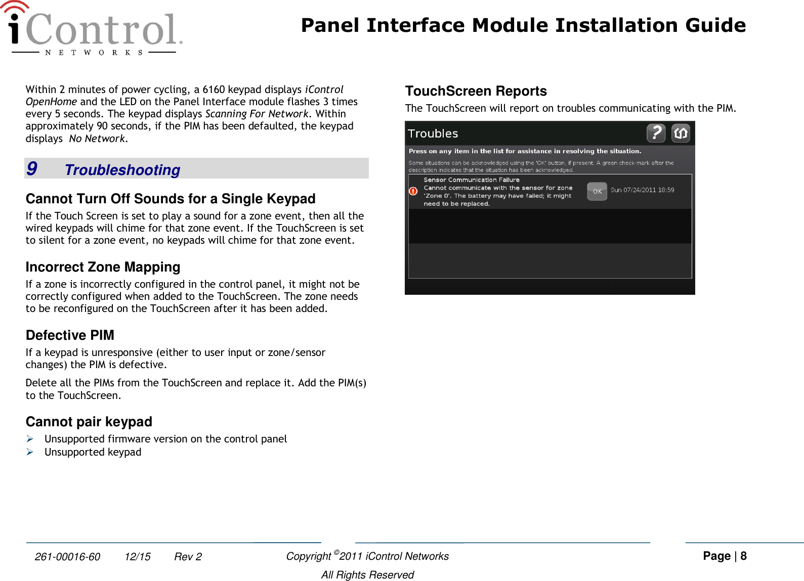
![Panel Interface Module Installation Guide Copyright ©2011 iControl Networks Page | 7 All Rights Reserved 261-00016-60 12/15 Rev 2 G. Tap Yes. The all the PIMs added to the TouchScreen are deleted. Additionally, all zones connected to the control panel are also removed from the iControl TouchScreen. This process might take up to 15 minutes depending on how many zones are connected to the control panel. The zones that were previously connected to the control panel are still programmed. If a PIM is re-paired with the TouchScreen, it finds the zones just as it did before. 7 Swapping a Panel Interface Module with a New One If a keypad does not respond to system changes (such as, zone status, keypad strokes), there is a possibility that the PIM is defective. If a PIM has been found to be defective, you must swap it out with a functional one. A. Review the zone numbering and the sensors connected through non-functioning control panel. B. Delete all installed PIMs from the system using the procedure Panel Interface from the TouchScreen as described in Section 6, Deleting a Panel Interface Module. C. Power down the control panel: 1. Remove the red and black flying leads from the battery located with the Vista control panel. 2. Remove the AC power. Note: It is important that steps 1 and 2 are performed in this order. D. Install the new PIM as described in Section 3, Installation Guidelines. E. Power up the control panel: 1. Return A/C power and then the red and black flying leads from the battery located in the control panel. 2. Within 2 minutes of applying power to the control panel, the PIM(s) are in search mode and ready to be paired with the Touchscreen. If the LED on a PIM does not blink three times each five seconds, there is a possibility that the PIM must be reset to factory default. See section 4. F. Add the PIM(s) to the TouchScreen as described in Section 4. G. Test the sensors connected through the control panel to ensure the TouchScreen recognizes when they are defaulted and that the connected zones can be bypassed using the keypad. 8 Setting the Panel Interface Module to Factory Default Perform the following steps within 10 minutes of power-up to set the PIM to factory default. Do not press any other keys on the keypad prior to the defaulting process. A. From the legacy keypad, press and hold the [1] and [*] keys at the same time momentarily. The legacy keypad beeps once. Otherwise, repeat this step. For all these steps, it is important to press the keys at the same time. If at any time during this procedure, the keypad beeps twice or chimes, you must disconnect the battery power from the control panel and start this process from the beginning. B. Press and hold the [3] and [#] keys at the same time momentarily. The legacy keypad beeps once. C. Press and hold the [1] and [*] keys at the same time momentarily. The legacy keypad beeps once. D. Press and hold the [3] and [#] keys at the same time momentarily. The legacy keypad beeps once. E. Power cycle the control panel.](https://usermanual.wiki/iControl-Networks/4000001604/User-Guide-1639898-Page-7.png)