iControl Networks 4000001604 Panel Interface Module User Manual SMCMT02 Z Motion Sensor Quick Start Guide
iControl Networks, Inc. Panel Interface Module SMCMT02 Z Motion Sensor Quick Start Guide
User Manual
iControl OpenHome™ Converge Panel Interface Module
Installation Guide
Congratulations on purchasing your Panel Interface module.
The iControl Networks, Inc. OpenHome Converge Panel Interface Module (PIM) is a professional state-of-the-art device that allows you to
manage your wired system and its sensors from your TouchScreen.
1 Overview
The Converge PIM is designed to allow the TouchScreen to takeover an
a previously installed wireless system so that its various elements
operate as part of the new overall security system.
The v2 PIM has 2 possible installation configurations:
- Multi Keypad configuration where the PIM is attached to the
alarm panel or wall mounted near the alarm panel. In this
configuration one PIM supports up to four supported traditional
security keypads. No traditional keypad can be left directly
connected to the security panel. Maximum of 4 keypads
supported.
- One PIM per keypad configuration where the PIM is placed in
the wall behind each supported traditional security system
keypad. In this configuration each keypad requires its own PIM
and no traditional keypad can be left directly connected to the
security panel. Maximum of 4 keypads supported.
Supported sensors are added as zones in TouchScreen of the proper
type IF they have been setup correctly in the legacy system
2 Technical Details
Physical Dimensions
Device
Height
Width
Depth
Printed circuit board
assembly (PCBA)
1-7/8 in (4.8 cm)
2-3/4 in (7 cm)
½ in (1.3 cm)
PCBA in plastic casing
2-5/8 in (6.6 cm)
3-1/2 in (9 cm)
3/4 in (1.9 cm)
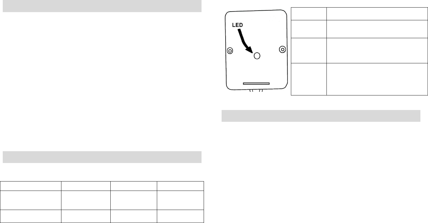
Voltage: 12VDC (power-limited)
Current: 120mA (LED lit)
LED Status
Condition
Description
On solid
Panel Interface module is in boot-
up mode.
Blinking
Panel Interface module is in
“locate mode” and is ready to be
paired with the TouchScreen.
Off
Normal operation
3 Installation Guidelines
Important: The PIM must be installed at least 0.3 inches (0.8 cm)
away from any metal structure and be used at distances of more
than 8 inches (20 cm) away from a location that a user will be
standing or sitting for extended periods.
The control panel system warranties are voided by the installation
of the Panel Interface Module.
Note: The TouchScreen can manage up to 31 total ZigBee devices
including the PIM(s) added to the system. However, the devices/zones
that are managed by the TouchScreen through the PIM do not add to
the device-count. For example, IF a) the control panel system is
managing 48 zones, and b) the TouchScreen is managing 30 ZigBee
devices plus a PIM connected to that keypad/ control panel, THEN the
total number of devices managed by the TouchScreen is 79.
A. Verify the system is working properly and the zones are programed
correctly.
B. Identify all the existing/connected Zones are working properly; it is
recommended to create a Zone list.
Panel Interface Module Installation Guide
Copyright ©2011 iControl Networks Page | 2
All Rights Reserved
261-00016-60 12/15 Rev 2
If the Zone numbers are not consecutive, the zone numbering order
will be modified when the control panel is taken over by the
TouchScreen. For example, if the zones are 1, 3, 5, 6 before
activation pairing, they will become 1, 2, 3, 4 after activation
pairing. Only the numbering is modified.
C. The PIM supports two separate installation configurations:
- Multi Keypad configuration (page 2)
A single PIM can control a maximum of four keypads
- One PIM per keypad configuration (page 3)
Up to four PIMs can be installed directly behind four keypads.
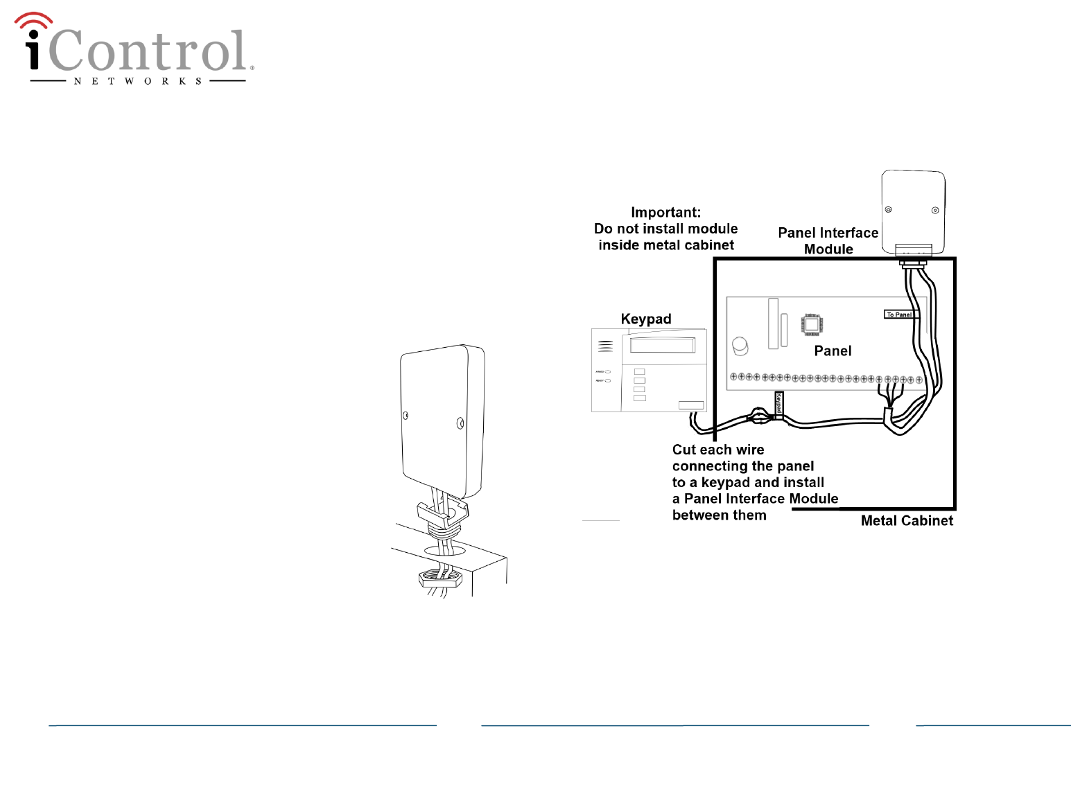
Multi Keypad configuration:
Perform the following steps AT THE METAL CABINET
containing the control panel to install a single PIM that
will control up to four keypads.
1. Remove the red and black flying leads from the
battery located in the control panel.
2. Remove the A/C power of the control panel by
unplugging the AC transformer from the wall
outlet.
3. Install the PIM into an aperture on top of the
cabinet shown in the figure to the left. Secure the
PIM with the nut.
Do not install the PIM inside the metal cabinet.
4. Cut the wire that connects the keypad to the
control panel.
5. Install the PIM between the control panel and the keypad as shown
in the following figure.
The PIM cable labeled To Keypad connects to the cables still
connected to the keypads. The PIM cable labed To Panel
connects to the cable coming from the control panel.
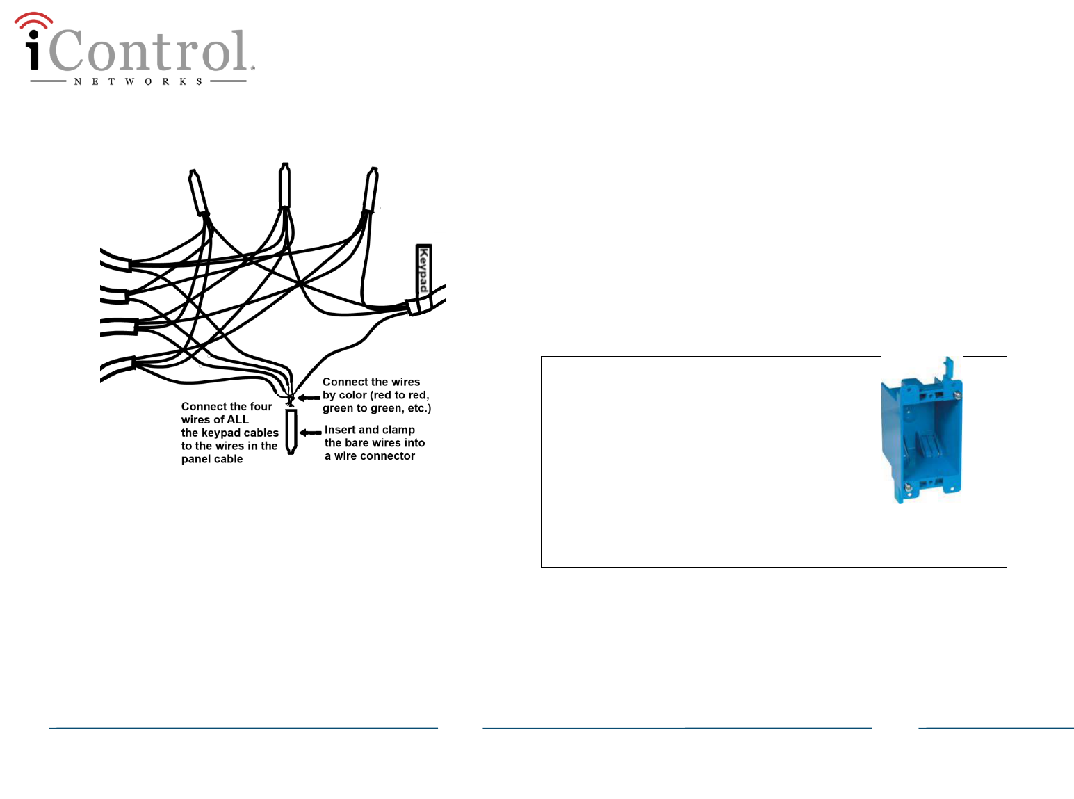
6. Connect wires based on their colors: red, black, green, and
yellow/white.
The wire colors identify their functions:
Yellow/white
Transmit from control panel to keypad
Green
Transmit from keypad to control panel
Red
DC power from the control panel to the keypad
Black
Panel Interface Module Installation Guide
Copyright ©2011 iControl Networks Page | 3
All Rights Reserved
261-00016-60 12/15 Rev 2
7. Cover each connection with a wire connector as shown in the
following figure:
Do not leave an operational keypad directly connected to the
control panel. Doing so renders the control panel inoperable.
8. Reconnect power to the control panel by plugging in the A/C
transformer and then re-connect the red and black flying leads to
the back-up battery located in the control panel.
9. Within 90 seconds of applying power to the control panel the PIM(s)
are in locate mode and ready to be paired with the Touchscreen.
If the status LED on the PIM is NOT blinking three times every
five seconds, it is possible that the PIM needs to be reset to
factory default.
A phone line is no longer needed for the control panel. The
TouchScreen uses a Broadband connection as the primary
communication path, with GPRS cellular back-up as a secondary
path. It is recommended to disconnect the gray 620 cord from
the RJ31X jack .
10. Within 90 seconds of applying power to the control panel the PIM(s)
are in locate mode and ready to be paired with the Touchscreen.
One PIM per keypad configuration
Up to four PIMs can be installed directly behind four keypads.
One PIM is in direct communication with the TouchScreen (alpha).
The rest of the PIMs communicate with the TouchScreen through
the alpha PIM.
For UL/ETL applications:
The Panel Interface module is installed between
the keypad and the control panel. If it is removed
from its plastic casing, then it is installed within
an industry standard PVC box. This box must be
designed and listed for use with non-metallic
sheathed cable in accordance with Article 314 of
the National Electrical Code®. All boxes must be
listed to UL514C. This box is not provided as part
of the installation kit. It must be provided by the
installer.
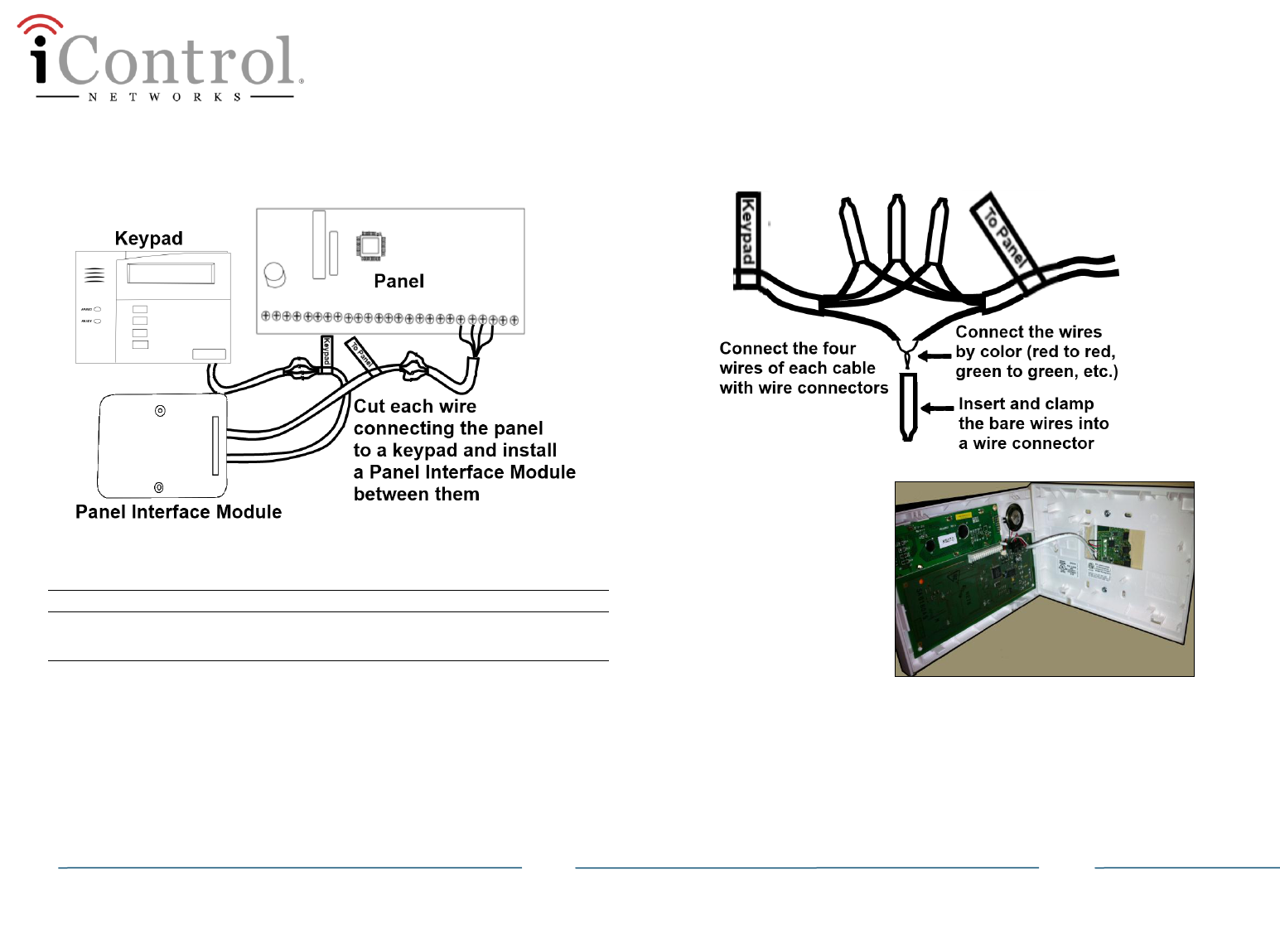
Perform the following steps BEHIND EACH KEYPAD.
1. Remove the red and black flying leads from the battery located in
the control panel.
2. Remove the A/C power of the control panel by unplugging the AC
transformer from the wall outlet.
3. Cut the wire that connects the keypad to the control panel.
Panel Interface Module Installation Guide
Copyright ©2011 iControl Networks Page | 4
All Rights Reserved
261-00016-60 12/15 Rev 2
4. Install the PIM between the control panel and the keypad as shown
in the following figure. Connect wires based on their colors: red,
black, green, and yellow/white.
The wire colors identify their functions:
Yellow/white
Transmit from control panel to keypad
Green
Transmit from keypad to control panel
Red
DC power from the control panel to the keypad
Black
5. Cover each connection with a wire connector as shown in the
following figure:
6. Reattach the keypad to
the mounting surface.
7. Repeat the above steps
for each keypad.
Remember, one PIM is
required for each
operational keypad.
Do not leave an operational keypad directly connected to the
control panel! Doing so renders the control panel inoperable.
8. Reconnect power to the control panel by plugging in the AC
transformer and then re-connect the red and black flying leads to
the back-up battery located in the control panel.
9. Within 90 seconds of applying power to the control panel the PIM(s)
are in locate mode and ready to be paired with the Touchscreen.

Panel Interface Module Installation Guide
Copyright ©2011 iControl Networks Page | 5
All Rights Reserved
261-00016-60 12/15 Rev 2
4 Adding a Panel Interface Module
Typically the PIM is added to the TouchScreen during the initial
Activation as described in the Home Installation Guide. The
following procedure is used when a PIM is added after
Activation.
A. Before beginning this process, record the Zone names assigned to
each zone and their zone numbers.
B. From the TouchScreen Home screen, tap the Settings app.
C. When the TouchScreen Keypad screen appears, enter the Installer
keypad code (this code is the same for all TouchScreens installed
by your company).
D. When the Technician keyboard pad appears, enter your Technician
ID and select Done. The Technician Settings menu appears
E. Select Home Devices. The Home Devices menu is displayed.
F. Tap Panel Interface > Add Panel Interface Boards. The Locating
Key Pads screen is displayed.
The PIM can be located only within the first 90 seconds of being
powered up. If keypad screen should display “Scanning for
Network.”
If it displays “No Network Found”, then press any button on the
keypad to restart the process or cycle power to the PIM.
Remember that a zone managed by the control panel might
have multiple sensors within that zone. When these zones are
paired with the TouchScreen, they will be located as a single
sensor. For example, a wired zone that has five window sensors
(in series) will be managed by the TouchScreen as if it were a
single sensor.
G. Tap Next. The TouchScreen scans the premises for PIM(s) that can
be paired, which must meet the following requirements:
- Defaulted
- Not currently paired with another TouchScreen
- In Search Mode (LED blinking 3 times every 5 seconds)
H. Follow the TouchScreen prompts to complete the add process and
pair the PIM with the TouchScreen. When the TouchScreen asks
that you trip to pair the PIM, press any number on the keypad.
If ALL available installed PIMs are not found, select Done to
return to the Technician Settings menu without adding.
I. When a panel is paired with the TouchScreen, any LEGACY key fobs
previously paired with the system are deleted/disabled. They will
not be used with new system.
J. When all the PIMs are located and paired, select Next. The
TouchScreen begins locating the zones connected to the control
panel. This operation can take a few minutes. When all the zones
are found, an icon is displayed for each zone in the Configure Panel
Interface Sensors screen.
Note: When zones connected to the control panel are found by
the TouchScreen, it automatically configures their functionality
(for example, Entry/Exit, Perimeter, etc.) and sensor type (for
example, Door/Window, Motion Detector, etc.) based on
various criteria. Section 11 Zone Auto-Configuration describes
the mapping of sensors that are auto-configured by the
TouchScreen. It is necessary to review the newly added sensors
to determine whether they require manual configuration.
K. Tap a Zone icon to configure the following:
o Display icon (such as a window or door icon)
o Zone Function (Entry/Exit, Perimeter, or 24-Hour Inform)
o Zone Label (a user-defined identifier for the zone)
L. After all the zones are configured, tap Next.

Panel Interface Module Installation Guide
Copyright ©2011 iControl Networks Page | 6
All Rights Reserved
261-00016-60 12/15 Rev 2
Additional sensors can be added and managed from the
TouchScreen. Additional sensors cannot be added to the control
panel after a PIM has been paired with the TouchScreen.
5 Managing the System from the Keypad
The following operations can still be performed from the control panel
keypad(s):
Arm Stay
Arm Away
Zone Bypass
No other keypad features are supported. Panic buttons, On/Off, and
Communications Test can no longer be performed from the keypad
after the control panel and zones have been paired with the
TouchScreen. These functions are now performed from the
TouchScreen.
Arming the System Zones
To use the legacy keypad to Arm the system:
A. Enter your 4 –digit keypad code plus the desired arming state
(below).
B. Press Away to arm the system in Arm Away mode (or 2, if there is
no dedicated key).
Press Stay to arm the system in Arm Stay mode (or 3, if there is no
dedicated key).
Press Instant to arm the system in Arm Night mode (or 7, if there is
no dedicated key).
Disarming the System Zones
To use the legacy keypad to Disarm the system:
A. Enter your user code.
B. Press 1 to disarm the system.
Bypassing Zones
To use the legacy keypad to bypass a zone:
A. Enter your user code.
B. Press Bypass (or 6, if there is no dedicated bypass key).
C. Press the two-digit zone number.
6 Deleting a Panel Interface Module
Deleting a PIM removes all associations with the control panel from the
TouchScreen.
To delete a PIM from the TouchScreen:
A. From the TouchScreen Home screen, select the Settings app.
B. When the TouchScreen Keypad screen appears, enter the Installer
keypad code (this code is the same for all TouchScreens installed
by your company).
C. When the Technician keyboard pad appears, enter your Technician
ID and select Done. The Technician Settings menu is displayed.
D. Select Home Devices. The Home Devices menu is displayed.
E. Tap Panel Interface > Delete Panel Interface Boards. The Remove
Panel Interface Boards and Zones screen is displayed.
F. Tap Next. A confirmation dialog is displayed that says “Are you
sure you want to remove all PIMs and zones?
Congratulations!
You have successfully added your PIMs. Your legacy system
keypad can now be used to enter keypad codes to arm/disarm
the iControl OpenHome Converge system as well as turn off
zones (bypass zones). Additionally, the legacy keypad
information screen displays messages from the iControl
system.

Panel Interface Module Installation Guide
Copyright ©2011 iControl Networks Page | 7
All Rights Reserved
261-00016-60 12/15 Rev 2
G. Tap Yes.
The all the PIMs added to the TouchScreen are deleted. Additionally,
all zones connected to the control panel are also removed from the
iControl TouchScreen.
This process might take up to 15 minutes depending on how
many zones are connected to the control panel. The zones that
were previously connected to the control panel are still
programmed. If a PIM is re-paired with the TouchScreen, it
finds the zones just as it did before.
7 Swapping a Panel Interface Module with a
New One
If a keypad does not respond to system changes (such as, zone status,
keypad strokes), there is a possibility that the PIM is defective. If a PIM
has been found to be defective, you must swap it out with a functional
one.
A. Review the zone numbering and the sensors connected through
non-functioning control panel.
B. Delete all installed PIMs from the system using the procedure Panel
Interface from the TouchScreen as described in Section 6, Deleting
a Panel Interface Module.
C. Power down the control panel:
1. Remove the red and black flying leads from the battery located
with the Vista control panel.
2. Remove the AC power.
Note: It is important that steps 1 and 2 are performed in this order.
D. Install the new PIM as described in Section 3, Installation
Guidelines.
E. Power up the control panel:
1. Return A/C power and then the red and black flying leads from
the battery located in the control panel.
2. Within 2 minutes of applying power to the control panel, the
PIM(s) are in search mode and ready to be paired with the
Touchscreen.
If the LED on a PIM does not blink three times each five
seconds, there is a possibility that the PIM must be reset to
factory default. See section 4.
F. Add the PIM(s) to the TouchScreen as described in Section 4.
G. Test the sensors connected through the control panel to ensure the
TouchScreen recognizes when they are defaulted and that the
connected zones can be bypassed using the keypad.
8 Setting the Panel Interface Module to
Factory Default
Perform the following steps within 10 minutes of power-up to set the
PIM to factory default. Do not press any other keys on the keypad prior
to the defaulting process.
A. From the legacy keypad, press and hold the [1] and [*] keys at the
same time momentarily. The legacy keypad beeps once.
Otherwise, repeat this step.
For all these steps, it is important to press the keys at the
same time. If at any time during this procedure, the keypad
beeps twice or chimes, you must disconnect the battery power
from the control panel and start this process from the
beginning.
B. Press and hold the [3] and [#] keys at the same time momentarily.
The legacy keypad beeps once.
C. Press and hold the [1] and [*] keys at the same time momentarily.
The legacy keypad beeps once.
D. Press and hold the [3] and [#] keys at the same time momentarily.
The legacy keypad beeps once.
E. Power cycle the control panel.
Panel Interface Module Installation Guide
Copyright ©2011 iControl Networks Page | 8
All Rights Reserved
261-00016-60 12/15 Rev 2
Within 2 minutes of power cycling, a 6160 keypad displays iControl
OpenHome and the LED on the Panel Interface module flashes 3 times
every 5 seconds. The keypad displays Scanning For Network. Within
approximately 90 seconds, if the PIM has been defaulted, the keypad
displays No Network.
9 Troubleshooting
Cannot Turn Off Sounds for a Single Keypad
If the Touch Screen is set to play a sound for a zone event, then all the
wired keypads will chime for that zone event. If the TouchScreen is set
to silent for a zone event, no keypads will chime for that zone event.
Incorrect Zone Mapping
If a zone is incorrectly configured in the control panel, it might not be
correctly configured when added to the TouchScreen. The zone needs
to be reconfigured on the TouchScreen after it has been added.
Defective PIM
If a keypad is unresponsive (either to user input or zone/sensor
changes) the PIM is defective.
Delete all the PIMs from the TouchScreen and replace it. Add the PIM(s)
to the TouchScreen.
Cannot pair keypad
Unsupported firmware version on the control panel
Unsupported keypad
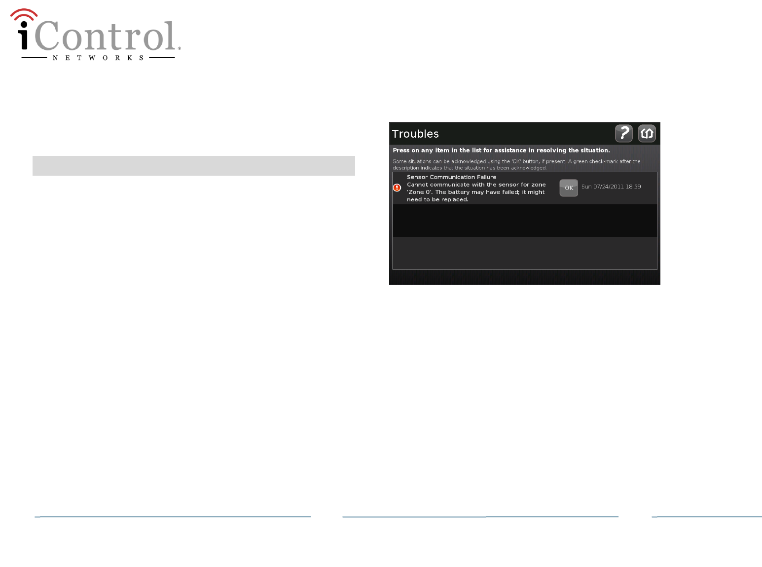
TouchScreen Reports
The TouchScreen will report on troubles communicating with the PIM.

Panel Interface Module Installation Guide
Copyright ©2011 iControl Networks Page | 9
All Rights Reserved
261-00016-60 12/15 Rev 2
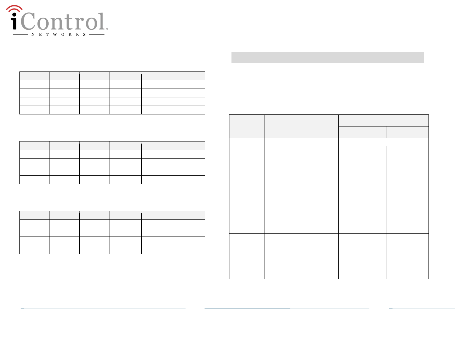
10 Supported Control Panels
Note: See the following subsections for supported devices for the
control panels
The following Ademco control panels are supported:
Vista 15P v3.0 or greater - To verify, open the panel and ensure
the chip is labeled WA15Pxx-N.n where N >= 3.
Vista 20P v3.0 or greater To verify, open the panel and ensure the
chip is labeled WA20Pxxx-N.n where N >= 3.
The version of firmware on an control panel cannot be
modified.
The following DSC control panels are supported:
PC1616,
PC1832
PC1864
PC580 (Power 432)
PC1555 Classic (Power 632)
PC1555MX (Power 632)
PC5010 (Power832)
PC5020 (Power864)
Ademco Panels: Supported Keypads
The following control panel keypads are supported for both types of
Honeywell keypads:
Honeywell 6148 Fixed-English Keypad
- Supports fixed-English LCD display
- 12 keys
- 2 status LEDs(Armed and Ready)
Honeywell 6150 Keypad
- Supports fixed-text display
- 16 keys
- 2 status LEDs(Armed and Ready)
Honeywell 6160 Alpha Display Keypad
- Supports 32-character message display
- 16 keys, including 4 function keys
- 2 status LEDs (Armed and Ready)
Honeywell 6160V Talking Alpha Display Keypad
- Supports 32-character message display
- 16 keys, including 4 function keys
- 3 status LEDs (Armed, Ready, and Message)
- Record and Playback voice messages are not supported
- 6160RF not supported
Keypads should say “Honeywell” on cover; however, they are
sometimes re-branded and a decal is placed over the
“Honeywell” logo
Panel Interface Module Installation Guide
Copyright ©2011 iControl Networks Page | 10
All Rights Reserved
261-00016-60 12/15 Rev 2
Ademco Vista System:
Auxiliary Device Current Draw Worksheet
The current draw for the Honeywell Vista 15P and 20P is a maximum of
600mA. Use the following worksheet to calculate the total current draw
from the system. If the devices connected to the Vista 15P or 20P
exceed the maximum draw threshold, you need to add an auxiliary
power supply to the system.
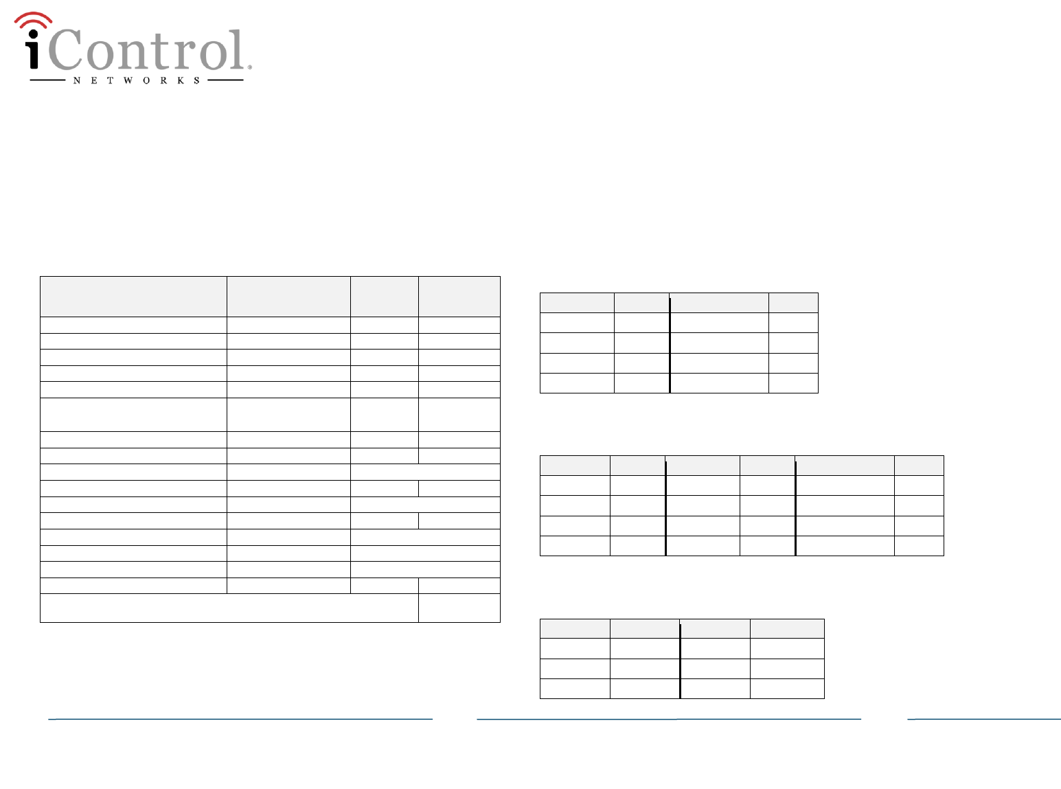
Honeywell Vista Auxiliary Device Current Draw Worksheet
Device
Current
No. of
Devices
TOTAL
CURRENT
Panel Interface module
120mA
Hardwired Motion Detectors*
25-30mA* (approx.)
4219 Zone Expander
30mA
4229 Zone Expander/Relay Unit
100mA
Hardwired Glassbreak Detectors*
25mA* (approx.)
Hardwired Smoke Detectors*
5mA* (standby)
130mA* (alarm)
5881/5882 RF Wireless Receiver
60mA
5883 RF Wireless Transceiver
80mA
6148 Fixed-English Keypad
55mA**
NOT SUPPORTED
6150 Keypad
70mA
6150V Keypad
NOT SUPPORTED
6160 Alpha Display Keypad
150mA **
6160V Alpha Display Voice Keypad
190mA **
NOT SUPPORTED
6270 TouchCenter keypad
NOT SUPPORTED
8132/8142 Touchscreen keypad
NOT SUPPORTED
(Current available from Aux. terminals = 600mA max.)
TOTAL=
* If using hardwire devices such as smoke detector, glassbreak, and/or motion detectors,
refer to the manufacture specifications for that particular unit’s current draw. The above
current calculations are approximate.
** Values are for devices in alarm; alarm for a keypad means armed with backlighting on
and sounder active.
DSC Panels:
Supported Keypads
This section lists the control panels currently supported by the PIM and
the supported associated keypads.
PC1616, PC1832, PC1864
The following keypads are supported for these DSC panel types:
Keypad
Type
Keypad
Type
PC5532Z
LED
PK5500 RFK5500
ICON
PK5501 RFK5501
LCD
PK5508 RFK5508
LED
PK5516 RFK5516
LED
PC580 (Power 432)
The following keypads are supported for this DSC panel type:
Keypad
Type
Keypad
Type
Keypad
Type
LCD5500Z
LCD
PC5508Z
LED
PK5500 RFK5500
ICON
PC5516Z
LED
PK5501 RFK5501
LCD
PC5532Z
LED
PK5508 RFK5508
LED
PK5516 RFK5516
LED
PC1555 Classic (Power 632)
The following keypads are supported for this DSC panel type:
Keypad
Type
Keypad
Type
LCD5500Z
LCD
PC5508Z
LED
PC5516Z
LED
PC5532Z
LED
Panel Interface Module Installation Guide
Copyright ©2011 iControl Networks Page | 11
All Rights Reserved
261-00016-60 12/15 Rev 2
PC1555MX (Power 632)
The following keypads are supported for this DSC panel type:
Keypad
Type
Keypad
Type
Keypad
Type
LCD5500Z
LCD
PC5508Z
LED
PK5500 RFK5500
ICON
LCD5501Z
LCD
PC5516Z
LED
PK5501 RFK5501
LCD
LCD5501Z32
ICON
PC5532Z
LED
PK5508 RFK5508
LED
PK5516 RFK5516
LED
PC5010 (Power832)
The following keypads are supported for this DSC panel type:
Keypad
Type
Keypad
Type
Keypad
Type
LCD5500Z
LCD
PC5508Z
LED
PK5500 RFK5500
ICON
LCD5501Z
LCD
PC5516Z
LED
PK5501 RFK5501
LCD
LCD5501Z32
ICON
PC5532Z
LED
PK5508 RFK5508
LED
PK5516 RFK5516
LED
PC5020 (Power864)
The following keypads are supported for this DSC panel type:
Keypad
Type
Keypad
Type
Keypad
Type
LCD5500Z
LCD
PC5508Z
LED
PK5500 RFK5500
ICON
LCD5501Z
LCD
PC5516Z
LED
PK5501 RFK5501
LCD
LCD5501Z32
ICON
PC5532Z
LED
PK5508 RFK5508
LED
PK5516 RFK5516
LED
11 Zone Auto-Configuration
During the “Locating Sensor” step, the TouchScreen identifies the
zones monitored by the control panel and maps them as specific sensor
types and functionality types. After pairing the sensors with the
TouchScreen, ensure that the sensors and zones have been properly
mapped. A zone mapping worksheet is available separately.
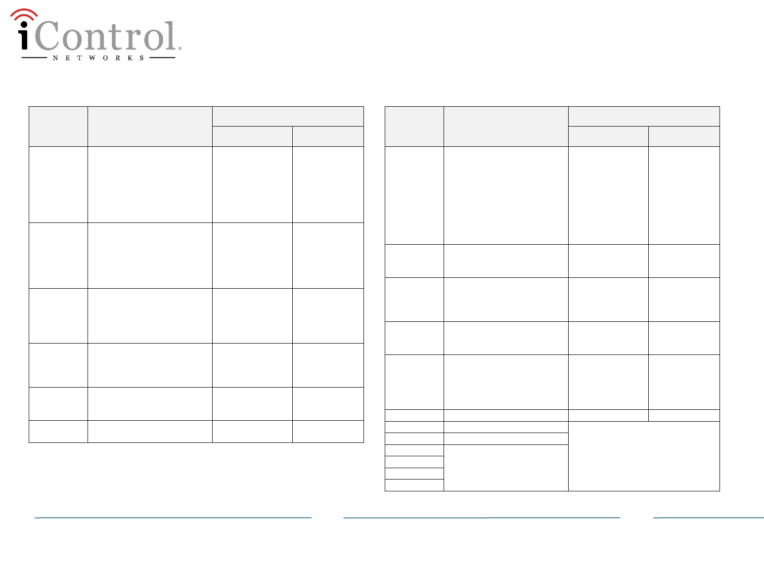
Ademco: Control Panel Zone Types Auto-Configured by TouchScreen
Zone Type
Code
Vista Zone Type
Mapped to TouchScreen
Zone Type
Sensor Type
00
Zone Not Used (bypassed)
Ignored
01
Entry/Exit Burglary Zone
Entry/Exit Zone
Door
02
03
Perimeter Burglary
Perimeter
Window
04
Interior Follower
Interior Follower
Motion Detector
05
Trouble by Day/Alarm by Night
Provides an instant alarm if
faulted when armed in the
Away, Stay, Night-Stay, Instant
or Maximum (night) modes.
During the disarmed state
(day), the system will provide a
latched trouble sounding from
the keypad
Entry/Exit Zone
Type
Door
06
24-hour Silent Alarm
Usually assigned to a zone
containing an emergency
button.
Sends a report to the central
station but provides no keypad
display or sounding.
Panic
Door
Panel Interface Module Installation Guide
Copyright ©2011 iControl Networks Page | 12
All Rights Reserved
261-00016-60 12/15 Rev 2
Ademco: Control Panel Zone Types Auto-Configured by TouchScreen
Zone Type
Code
Vista Zone Type
Mapped to TouchScreen
Zone Type
Sensor Type
07
24-hour Audible Alarm
Assign to a zone that has an
emergency button.
Sends a report to the central
station, and provides an alarm
sound at the keypad, and an
audible external alarm.
Panic
Door
08
24-hour Auxiliary Alarm
Assign to a zone containing an
emergency button, or to a
zone containing monitoring
devices such as water or
temperature sensors.
Audible 24 Hour
Water Sensor
09
Supervised Fire
Provides a fire alarm on short
circuit and a trouble condition
on open circuit. A fire alarm
produces a pulsing bell output.
Fire 24 Hour
Smoke Alarm
10
Interior w/Delay
Provides entry delay if tripped
when the panel is armed in the
Away mode.
Interior Follower
Motion Detector
12
Monitor Zone
A dynamic monitor of a zone
fault/trouble (not alarm).
24 Hour Inform
Door
14
24 Hour Carbon Monoxide
Monitor
Entry/Exit Zone
Type
Door
Ademco: Control Panel Zone Types Auto-Configured by TouchScreen
Zone Type
Code
Vista Zone Type
Mapped to TouchScreen
Zone Type
Sensor Type
16
Fire w/Verification
Provides a fire alarm when
zone is shorted, but only after
alarm verified. • System
verifies alarm by resetting
zones for 12 seconds after
short is detected. A
subsequent short circuit within
90 seconds triggers fire alarm.
Fire 24 Hour
Smoke Alarm
20
Arm-Stay
Arms the system in Stay mode
when the zone is activated.
Entry/Exit Zone
Type
Door
21
Arm-Away
Arms the system in Away
mode when the zone is
activated.
Entry/Exit Zone
Type
Door
22
Disarm
Disarms the system when the
zone is activated.
Entry/Exit Zone
Type
Door
23
No Alarm Response
Can be used on a zone when
an output relay action is
desired, but with no
accompanying alarm.
Entry/Exit Zone
Type
Door
24
Silent Burglary
Entry/Exit Zone
Door
77
Key Switch
Ignored
81
AAV Monitor
90
Configurable
91
92
93
Panel Interface Module Installation Guide
Copyright ©2011 iControl Networks Page | 13
All Rights Reserved
261-00016-60 12/15 Rev 2
DSC: Control Panel Zone Types Auto-Configured by TouchScreen
Zone Type
Code
Vista Zone Type
Mapped to TouchScreen
Zone Type
Sensor Type
00
Zone Not Used (bypassed)
Ignored
01
02
03
04
05
06
07
08
09
10
12
14
16
20
21
22
23
24
77
81
90
91
92
93

Panel Interface Module Installation Guide
Copyright ©2011 iControl Networks Page | 14
All Rights Reserved
261-00016-60 12/15 Rev 2
iControl Networks
Model: 4000001604
FCC ID Y6Q-4000001604
IC: 9454A-4000001604
Compliances
FCC Notice
This device has been designed, constructed, and tested for compliance
with FCC Rules that regulate intentional and unintentional radiators. As
the user of this device, you are not permitted to make any alterations
or modifications to this equipment or to use it in any way that is
inconsistent with the information described in this quick-start guide,
without the express written permission of SMC Networks. Doing so will
void your warranty to operate this equipment.
The exterior of the device should be labeled with the following
instructions “Zigbee Panel Interface module is integrated with
“Contains FCC ID: Y6Q-SMCTB01Z” and “Contains IC ID 9454A-
SMCTB01Z”.
This device complies with Part 15 of the FCC rules. Operation of this
device is subject to the following two conditions:
1) This device may not cause harmful interference, and
2) This device must accept any interference received, including
interference that may cause undesired operation.
The “IC” designation preceding the radio certification number indicates
that this device complies with the Industry of Canada specifications.
Limitations of Security Products
Security products and alarm systems do not offer guaranteed
protection against burglary, fire, or other emergencies. They may fail
to warn for diverse reasons, including (but not limited to): power
failure, dead batteries, improper installation, coverage, coverage areas
overlooked during installation, defeat by technically sophisticated
intruders, component failure, or inadequate maintenance. Alarm
systems should be checked weekly to ensure that all devices are
working properly.
AN ALARM SYSTEM IS NOT A SUBSTITUTE FOR INSURANCE

Panel Interface Module Installation Guide