iDevices SWITCH8 In-wall On/Off Smart Switch User Manual 15 IDEV0008 UserMan
iDevices, LLC In-wall On/Off Smart Switch 15 IDEV0008 UserMan
UserManual.wiki
>
iDevices
>
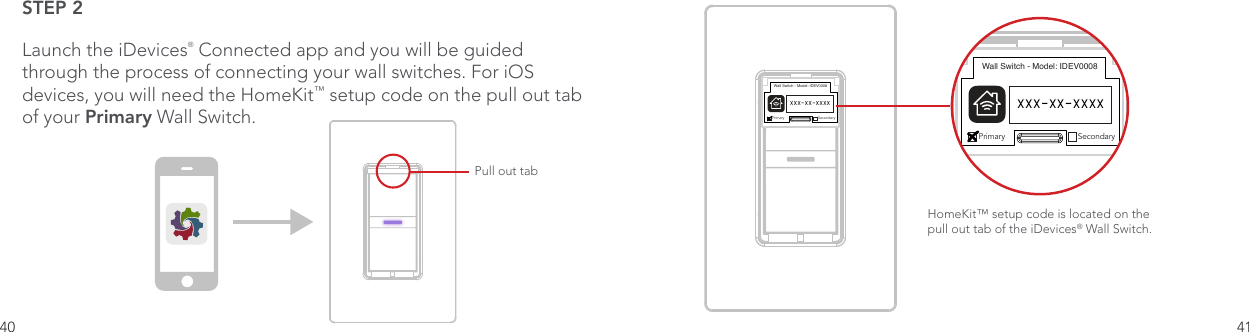
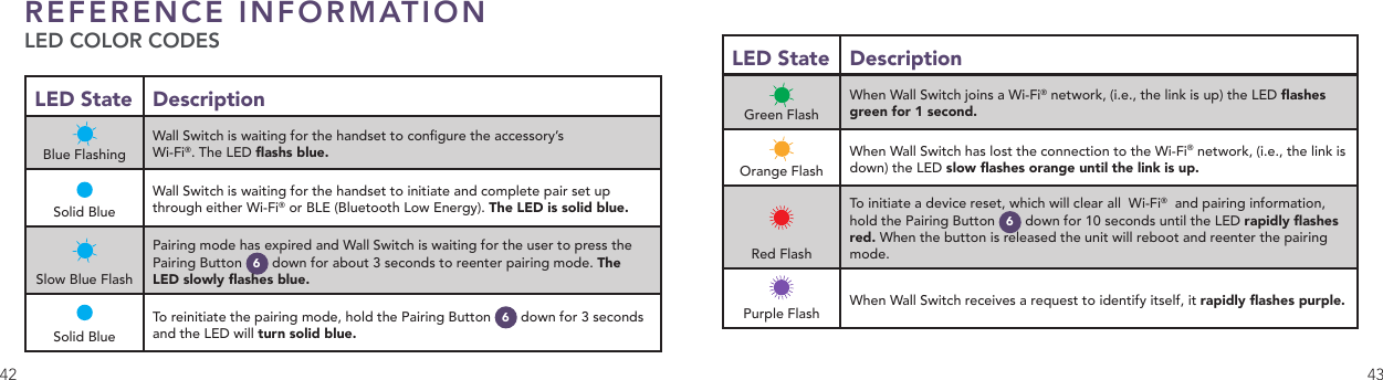
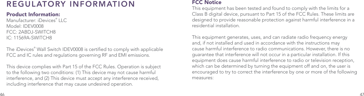
SWITCH8 User Manual
15_IDEV0008 UserMan
Navigation menu
Upload a User Manual
Namespaces
Wiki Guide
HTML
PDF
Info
Views
User Manual
Discussion / Help
Navigation