iMetrik DACP08 GSM Communication Device User Manual Installation Instructions
iMetrik GSM Communication Device Installation Instructions
iMetrik >
Installation Instructions

iMetrik Solutions Inc.
Support: 1(866) 276-5382
iMetrik Solutions Inc.
Support: 1(866) 276-5382
May 29
th
, 2007 - Form: Install-01 Ver 1.3
May 29
th
, 2007 - Form: Install-01 Ver 1.3
This device complies with Part 15 of the FCC Rules and with RSS-210 of Industry Canada.
Operation is subject to the following two conditions. (1) This device may not cause harmful
interference, and (2) this device must accept any interference received, including interference that
may cause undesired operation.
IMPORTANT NOTE:
FCC Radiation Exposure Statement:
This equipment complies with FCC radiation exposure limits set forth for an uncontrolled environment.
This equipment should be installed and operated with minimum distance of 20cm between the radiator
and your body. This transmitter must not be co-located or operating in conjunction with any other
antenna or transmitter.
Warning: Changes or modifications made to this equipment not expressly approved by iMetrik Inc may
void the FCC authorization to operate this equipment.
NOTE: This equipment has been tested and found to comply with the limits for a
Class B digital device, pursuant to Part 15 of the FCC Rules. These limits are
designed to provide reasonable protection against harmful interference in a
residential installation. This equipment generates, uses and can radiate radio
frequency energy and, if not installed and used in accordance with the
instructions, may cause harmful interference to radio communications. However,
there is no guarantee that interference will not occur in a particular installation.
If this equipment does cause harmful interference to radio or television reception, which can be
determined by turning the equipment off and on, the user is
encouraged to try to correct the interference by one or more of the following
measures:
-- Reorient or relocate the receiving antenna.
-- Increase the separation between the equipment and receiver.
-- Connect the equipment into an outlet on a circuit different from that to which the receiver is
connected.
-- Consult the dealer or an experienced radio/TV technician for help.
Note:
This Class B digital apparatus complies with Canadian ICES-003.
Cet appareil numérique de la classe B est conforme à la norme NMB-003 du Canada.
Installation instruction iMetrik DACP08
You are currently installing iMetrik DACP08 module. If you are unsure of any step of this process, please call our Customer
Care service at 1-899-276-5382. This package includes the following components: ONE DACP08 module, One GSM cellular
antenna, ONE GPS antenna, ONE power cable assembly; TWO starter-interrupt cables. (DACP08 only)
Installation notes
• To be install only inside vehicle cabin
• GPS antenna must be mounted so that no metal is impeding sky-view, rounded side up
• GSM antenna must be located on a non metallic area.
• See all the warnings and notes on last page before installation
•
No power should be applied to unit if antennas are not connected.
INSTALLATION PROCEDURE
1) Disconnect the battery from the vehicle electrical system
from this point forward, to avoid possible damage due to
shorting of exposed wire.
The unit must never be powered up without antennas
connection.
2) Locate power for constant 12V power and a good
ground (ignition off)
3) If holder is separate; connect the red wire from the
power cable assembly to one end of the fuse holder, and
the other end of the fuse holder to the constant 12V
power source.
4) Ground the black wire of the power cable assembly to
the vehicle’s frame. (ignore purple wires if present)
If installing a LR 200G, jump to step 7
5) Find the vehicle’s starter wire and cut it. The starter wire
only has 12V when cranking.
6) Connect the wires from the starter-interrupt cables to
each end of the starter wire. Connect the “Quick-
Release” connectors from the starter-interrupt cables to
the device.
Make sure all connections are soldered and well
insulated
Note: all components of the device (GPS/RF
antennas) should be installed behind the dashboard
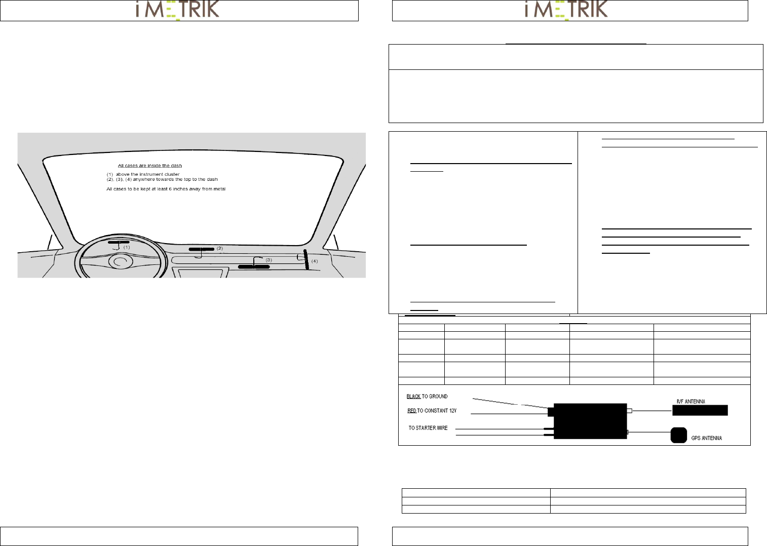
7) Install the RF antenna on a flat, non-metallic surface.
For best results, install in a vertical position six inches
away from any metal.
8) Screw the RF antenna into the device RF connector
9) Install the GPS antenna in the vehicle. Choose a
location where it has NO METAL impeding its view of
the sky. Connect the GPS antenna to the device.
10) Connect the 4-pin power cable to the device. Install the
iMETRIK 200G device in the vehicle.
When connecting or disconnecting either antenna
from the device, make sure to remove the 12V
power cable first. Severe damage to the unit may
result otherwise
11) Reconnect the vehicle’s battery.
12) Park the vehicle outside, away from trees or tall
buildings. Verify the installation was a success by
performing a “Location” command from your account.
WELL INSULATED
TESTING
LED 1:POWER 2:STARTER 3:GPS 4: CELLULAR
COLOR ► GREEN RED RED RED
OFF NO POWER ENABLED NO POWER/
GPS ERROR
NO POWER/
ERROR*
FAST BLINK N/A N/A ACQUIRING*** NETWORK ERROR
SLOW
BLINK N/A WARNING MODE HAS DATE/TIME ACQUIRING**
ON : POWER DISABLE MODE GOOD GPS FIX CONNECTED
* CELLULAR LED is OFF during the approximately 10 seconds after power-on. This is normal.
** Acquiring time of approximately 75 seconds during power-on. Users should wait at least 2 minutes before addressing the
device the first time.
*** GPS LED is OFF during the approximately 10 seconds after power-on. This is normal. GPS LED will stay off if there is a
cellular error on power-up.
- It is recommended to insulate the in-line fuse with shrink wrap or electrical tape
- Ensure fuse is properly inserted
S/N: IMEI:
YEAR: MAKE:
MODEL: VIN: