iRobot 4812 iROBOT COMMAND MODULE User Manual USERS MANUAL 1 OF 2
iRobot Corporation iROBOT COMMAND MODULE USERS MANUAL 1 OF 2
iRobot >
Contents
- 1. USERS MANUAL 1 OF 2
- 2. USERS MANUAL 2 OF 2
USERS MANUAL 1 OF 2
Getting Started with a PC
1
Install WinAVR from the Command Module product CD
2
Power on iRobot Create, plug the Command Module into the robot’s
Cargo Bay Connector, and connect the USB cable from your PC to
the Command Module.
3
Install the USB drivers (there are 2 that need to be installed) using
the Found New Hardware Wizard or the installation executable on the
Command Module product CD
4
Set the USB serial port to COM9 (open the Properties for the port from
the Device Manager and change the com port using the Advanced button
in the Port Settings tab)
Creating and Loading a New Project
1
Open WinAVR
2
Create a new project and add the source files (e.g. input.c, oi.h and
makefile from the input example program on the product CD)
3
Compile the project using Tools->[WinAVR] Make All
4
Connect the Command Module to iRobot Create and connect the
USB cable from your PC to the Command Module
5
Press Reset on the Command Module
6
Download the project using Tools->[WinAVR] Program
www.irobot.com
iRobot® Command Module
QUICK START GUIDE
SAVE 15%
on accessories.
See back for details.
An easy step-by-step guide and reference card for using
the iRobot Command Module with your iRobot Create.
TM
Virtual Wall®
IR transmitter
conveniently placed at
robot eye-level. Can be
used as an invisible
wall or beacon
iRobot
Rechargeable Battery
Rechargeable
battery and charger
for the iRobot Create
Home BaseTM
Recharges the iRobot
rechargeable battery
while in iRobot Create.
Also contains 3
IR transmitters
Standard Remote
Allows you to control
iRobot Create from
a distance
iRobot® CreateTM
Accessories
Register your iRobot® Command Module
today and SAVE 15% on all accessories.
*
©2006 iRobot Corporation. All rights reserved.
iRobot and Virtual Wall are registered trademarks of iRobot Corporation.
Home Base and Create are trademarks of iRobot Corporation.
U.S. Pat. Nos. 6,594,844 6,690,134, and 6,809,490. Other patents pending.
For more accessories and ordering information
go to www.irobot.com or call 800.727.9077.
*See registration card for details. Availability subject to change.
Shipping and handling not included.
429.06
For the full set of instructions on setting up and using your Command
Module visit www.irobot.com/create to download the Command Module
Owner’s Manual.
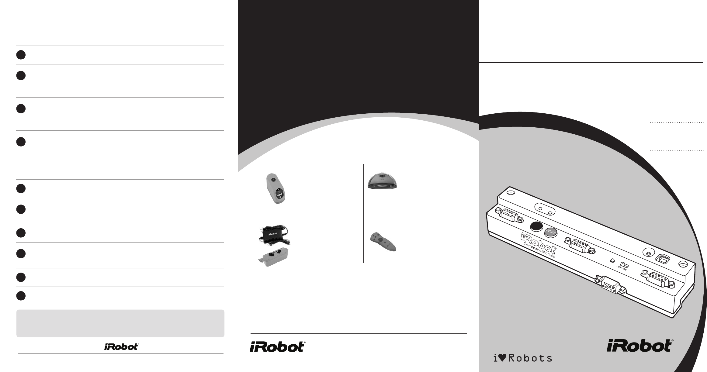
Introduction
With the iRobot Command Module, you can control iRobot Create with programs
you write in C or C++. And when you add custom hardware to the Command
Module and iRobot Create, you can invent almost any kind of robot you want.
The Command Module plugs into iRobot Create’s Cargo Bay connector and
screws down for a secure connection. Its four DB-9 expansion ports (ePorts)
make adding your own sensors, lights, and motors inexpensive and easy.
For more detail, download the Command Module Owner’s Manual at
www.irobot.com/create.
With the programs you write, you can control iRobot Create’s motors,
lights, and songs and read its sensors using the robot’s Open Interface
serial protocol (details are in the iRobot Create Owner’s Manual and online
at www.irobot.com/create). You can also control and read your own custom
sensors, buttons, LEDs, and motors when you connect them to the Command
Module’s expansion ports. Once you write your programs, they are easy to
download to the Command Module’s microcontroller.
Start with one of the example programs; expand and change it as you wish.
For more information on writing software for the Command Module see the
Software Reference chapter in the Command Module Owner’s Manual and the
Open Interface reference guide.
What’s included:
iRobot Command Module
USB Cable
iRobot Command Module CD that includes:
• WinAVR install
• USB Driver install
• Example programs
• Atmel AVR ATmega168 microcontroller data sheet
Processor I/O Pins
The Command Module’s Atmel AVR ATmega 168 microcontroller has
23 I/O pins, arranged into 3 ports (B, C and D), plus 2 additional analog
input pins. The table below gives a description of each pin along with the
location of the hardware to which it is connected. For information on
how to control and read from these pins, see the Command Module
Owner’s Manual.
Pin Name Description Location
PB0 Digital I/O Cargo Bay ePor t pin 3
PB1 Digital I/O Top Center ePor t pin 3
PB2 Digital I/O Top Right ePor t pin 2
PB3 Digital I/O Top Left ePor t pin 3
PB4 Serial port connector select. 1 = USB port.
0 = iRobot Create
Internal
PB5 iRobot Create Power Detect. High if iRobot Create
is on.
iRobot Create connector
pins 10-13
PB6 Clock line Internal Use only
PB7 Clock line Internal Use only
PC0 Digital I/O or Analog Input Cargo Bay ePor t pin 2
PC1 Digital I/O or Analog Input Top Center ePor t pin 2
PC2 Digital I/O or Analog Input Top Right ePor t pin 2
PC3 Digital I/O or Analog Input Top Left ePor t pin 2
PC4 Digital I/O or Analog Input Cargo Bay ePor t pin 1
PC5 Digital I/O or Analog Input Top Center ePor t pin 2
PC6 Reset Line Internal Use only
PD0 Serial Rx iRobot Create connector pin 2 or USB
PD1 Serial Tx iRobot Create connector pin 1 or USB
PD2 iRobot Create Device Detect Input iRobot Create connector pin 15
PD3 USB Detect USB port
PD4 Command Module Soft Button Left button
PD5 Command Module LED 1 Left green LED
PD6 Command Module LED 2 Right green LED
PD7 iRobot Create Power Toggle (on rising edge) iRobot Create connector pin 3
ADC6 Analog Input Top Right ePor t pin 1
ADC7 Analog Input Top Left ePor t pin 1
Top Right ePort
Pin# Description Name
1 Analog Input 6 ADC6
2 Digital I/O (Port C pin 2) or Analog Input 2 PC2/ADC2
3 Digital I/O (Port B pin 2) PB2
4 Regulated 5V voltage (when iRobot
Create is on)
Vcc
5 iRobot Create Battery Ground Gnd
6 Not Connected NC
7 iRobot Create Battery Voltage
(when iRobot Create is on)
Vpwr
8 Not Connected NC
9 Low Side Driver 0 LD0
Cargo Bay ePort
Pin# Description Name
1 Digital I/O (Port C pin 4) or Analog Input 4 PC4/ADC4
2 Digital I/O (Port C pin 0) or Analog Input 0 PC0/ADC0
3 Digital I/O (Port B pin 0) PB0
4 Regulated 5V voltage (when iRobot
Create is on)
Vcc
5 iRobot Create Battery Ground Gnd
6 Not Connected NC
7 iRobot Create Battery Voltage
(when iRobot Create is on)
Vpwr
8 Low Side Driver 1 LD1
9 Low Side Driver 2 LD2
Top Left ePort
Pin# Description Name
1 Analog Input 7 ADC7
2 Digital I/O (Port C pin 3) or Analog Input 4 PC3/ADC4
3 Digital I/O (Port B pin 3) PB3
4 Regulated 5V voltage (when iRobot
Create is on)
Vcc
5 iRobot Create Battery Ground Gnd
6 Not Connected NC
7 iRobot Create Battery Voltage
(when iRobot Create is on)
Vpwr
8 Not Connected NC
9 Low Side Driver 0 LD0
Top Center ePort
Pin# Description Name
1 Digital I/O (Port C pin 5) or Analog Input 5 PC5/ADC5
2 Digital I/O (Port C pin 1) or Analog Input 1 PC1/ADC1
3 Digital I/O (Port B pin 1) PB1
4 Regulated 5V voltage (when iRobot
Create is on)
Vcc
5 iRobot Create Battery Ground Gnd
6 Not Connected NC
7 iRobot Create Battery Voltage
(when iRobot Create is on)
Vpwr
8 Not Connected NC
9 Low Side Driver 0 LD0
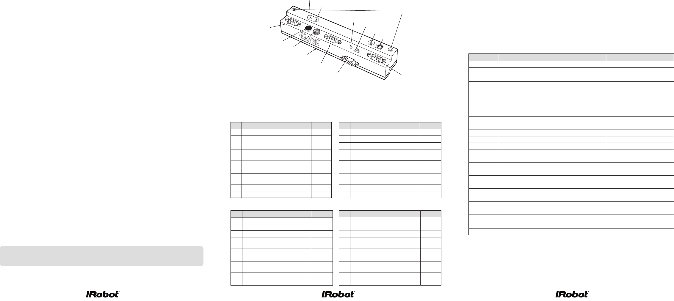
Anatomy LED 1
LED 2
Top Left ePort USB Indicator
USB
Hold Down Screws
Soft Button
Reset
Top Center ePort
Power LED
Power Switch
Cargo Bay ePort Top Right ePort
iRobot Create Connector
(under the Command Module)
System Requirements:
Windows XP*
USB connection
*Support for additional operating systems may be available at www.irobot.com/create.
The tables below show the signal connections for the each of the ePorts.
The four ePorts have similar electrical connections, allowing add-on modules
to be installed in different ePorts depending upon your needs.
For more details on your iRobot Command Module and to download the
Owner’s Manual, visit www.irobot.com/create.