ifm electronic DTC510R RFID read/write head User Manual
ifm electronic gmbh RFID read/write head
UserManual.wiki
>
ifm electronic
>
DTC510R User Manual
Manual
Navigation menu
Upload a User Manual
Namespaces
Wiki Guide
HTML
PDF
Info
Views
User Manual
Discussion / Help
Navigation
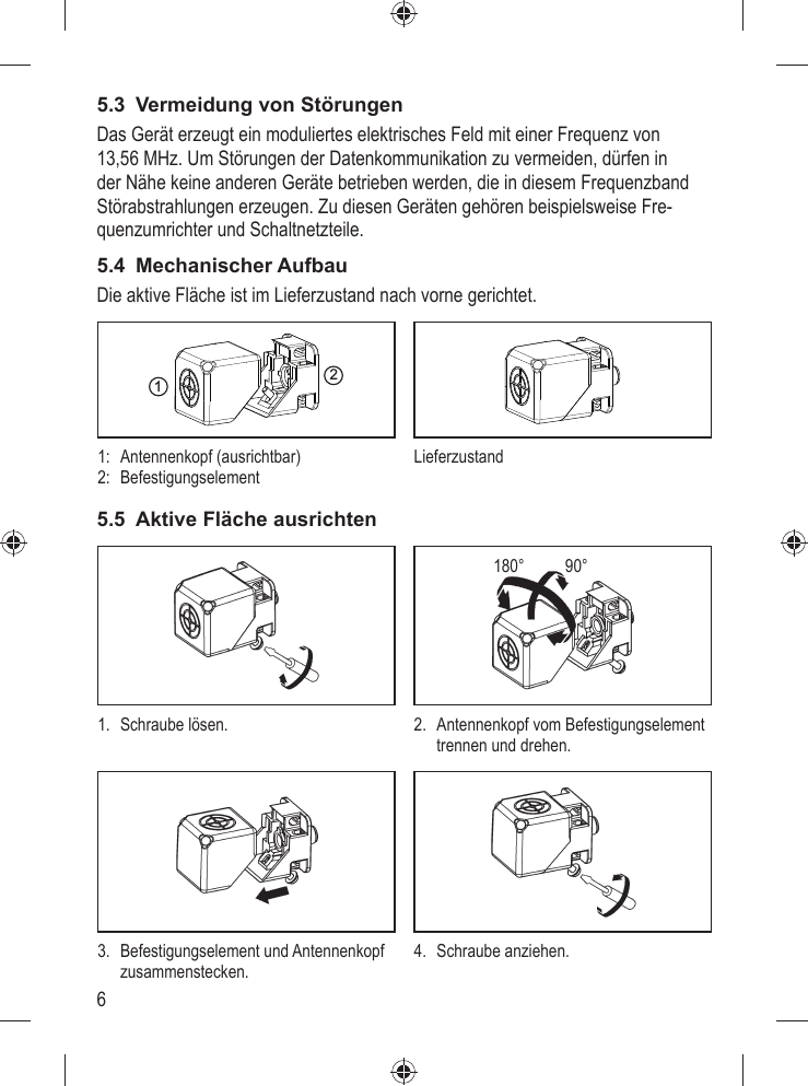
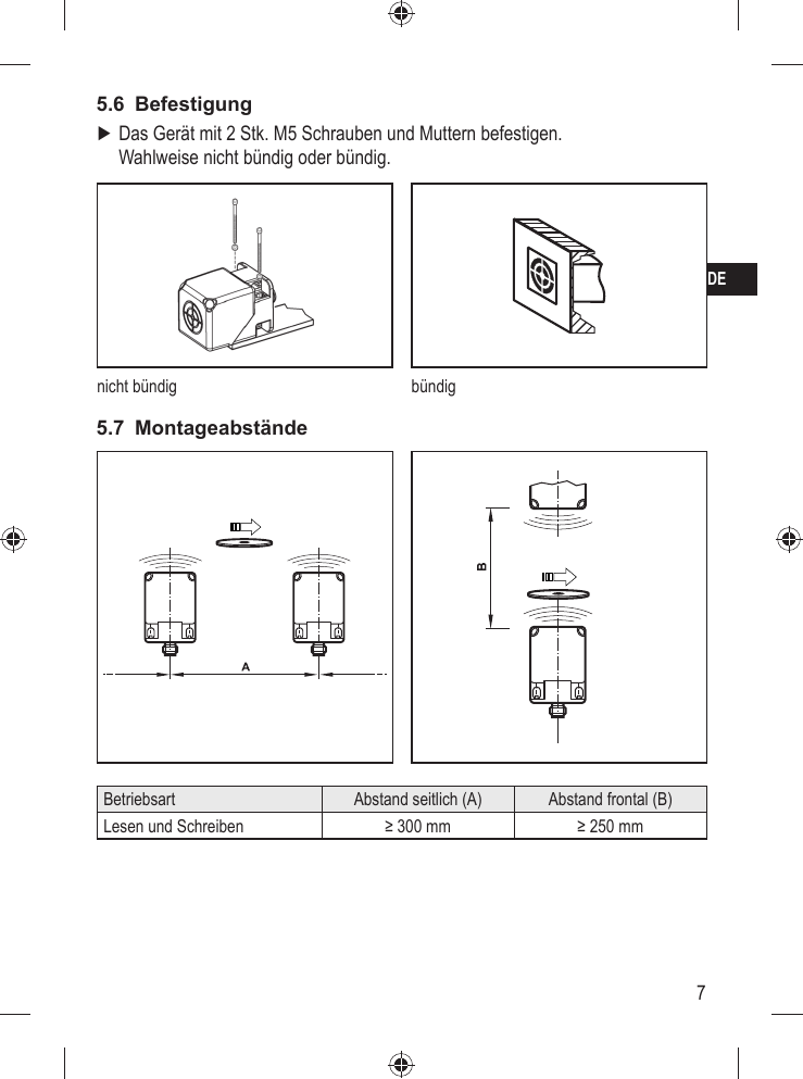
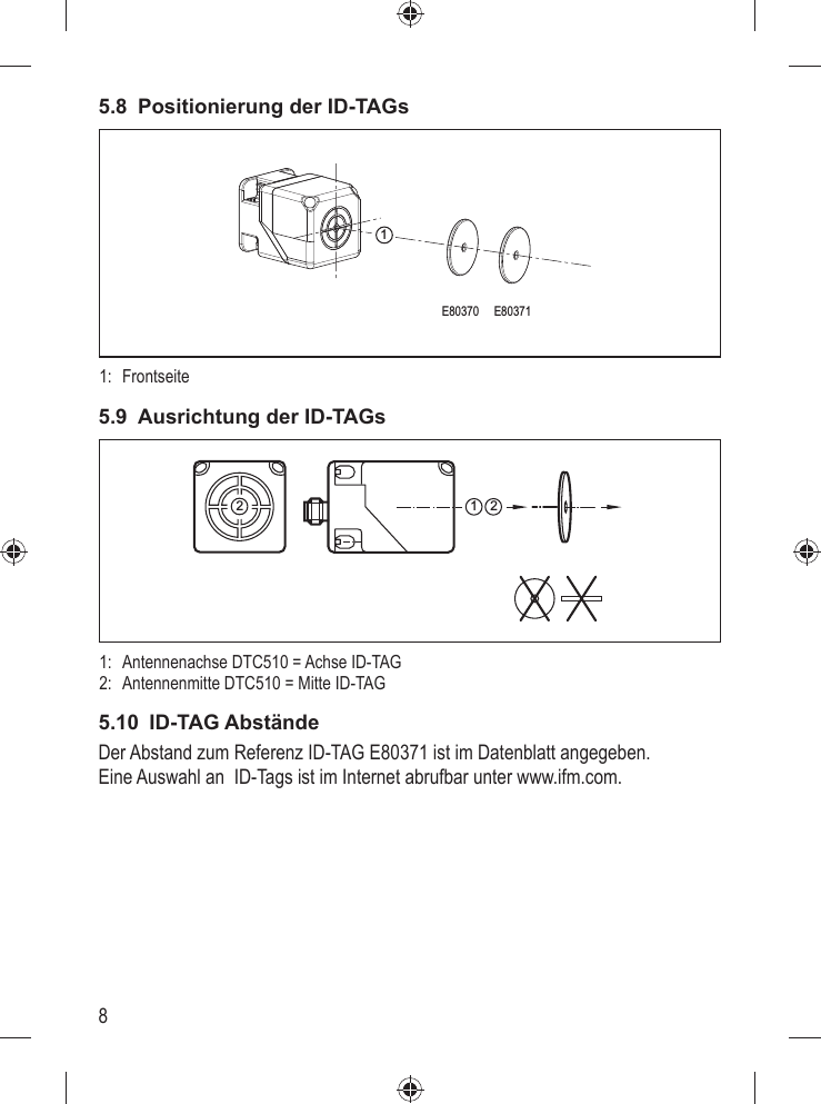
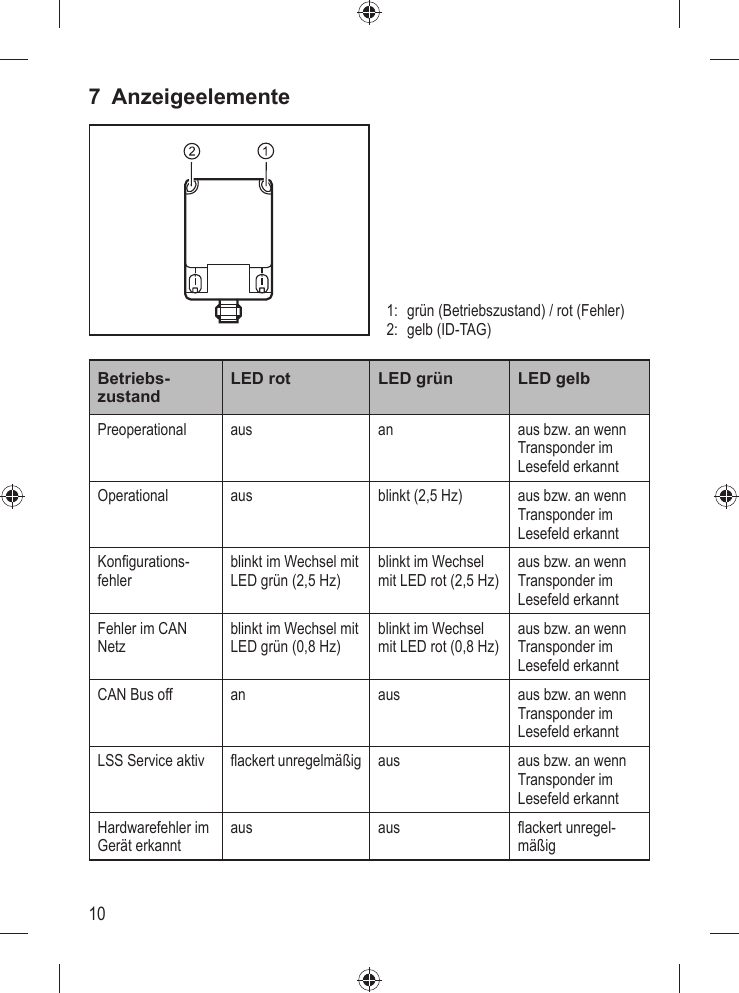
![5DE4.2 ÜbersichtArt.-Nr.:Funktion:Typbezeichnung:Arbeitsfrequenz:H x B x T [mm]:Max. Sendeleistung:DTC510Lese-/SchreibkopfDTCHF MCRWCOUS0313,56 MHz40 x 40 x 54200 mW5 Montage5.1 Generelle MontagehinweiseBei der Montage von mehreren Systemen die Mindestabstände zwischen den Lese-/Schreibköpfen beachten.Der bündige Einbau eines Lese-/Schreibkopfes in Metall verringert den Lese-/Schreibabstand. Die unmittelbare Nähe starker HF-Emissionsquellen, wie z.B. Schweißtra-fos oder Umformer, kann die Funktion der Lese-/Schreibköpfe beeinträch-tigen.Informationen zum erhältlichen Montagezubehör sind im Internet abrufbar unter www.ifm.com.5.2 Hinweise zur ID-TAG MontageDie Montage der ID-TAGs in/auf Metall verringert den Lese-/Schreibab-stand. Zur Positionierung der ID-TAGs sind die Lese-/Schreibköpfe auf der aktiven Fläche mit einem Antennensymbol versehen. Es kennzeichnet die Mitte der integrierten Antennenspule und muss mit der ID-TAG Mitte übereinstimmen.Die Ausrichtung der Lese-/Schreibkopf-Antennenachse muss mit der Achse der ID-TAG Spule übereinstimmen.](https://usermanual.wiki/ifm-electronic/DTC510R/User-Guide-3414485-Page-5.png)

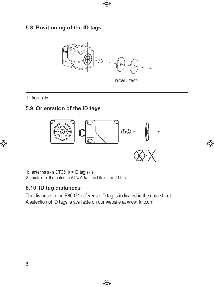
![5UK4.2 OverviewArt. no.:Function:Type designation:operating frequency:H X W X D [mm]:Max. transmission power:DTC510read/write headDTCHF MCRWCOUS0313.56MHz40 x 40 x 54200 mW5 Installation5.1 General installation instructionsWhen mounting several read/write heads adhere to the minimum distances between the systems.Flush mounting of a read/write head in metal reduces the read/write dis-tance. The immediate vicinity of powerful HF emission sources such as welding transformers or converters can affect operation of the read/write heads.Information on the available mounting accessories is available on our website at www.ifm.com. 5.2 Notes on ID tag mountingIf the ID tags are mounted in/on metal, the read/write distance is reduced. For positioning the ID tags the read/write heads are marked with an an-tenna symbol on the active face. It designates the middle of the integrated antenna coil and has to correspond with the middle of the ID tag.The orientation of the read/write head antenna axis must correspond with the axis of the ID tag coil.](https://usermanual.wiki/ifm-electronic/DTC510R/User-Guide-3414485-Page-17.png)
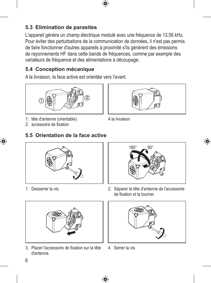
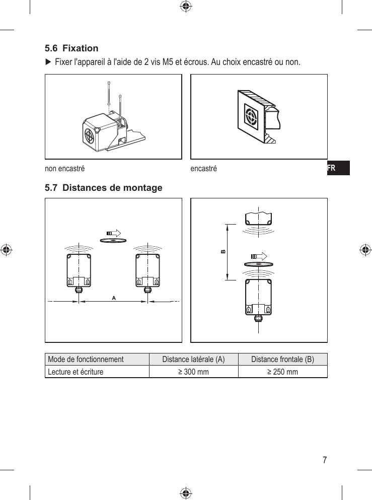
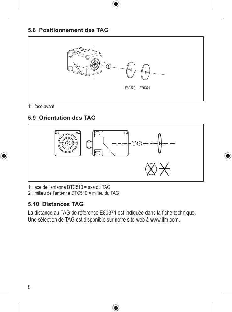
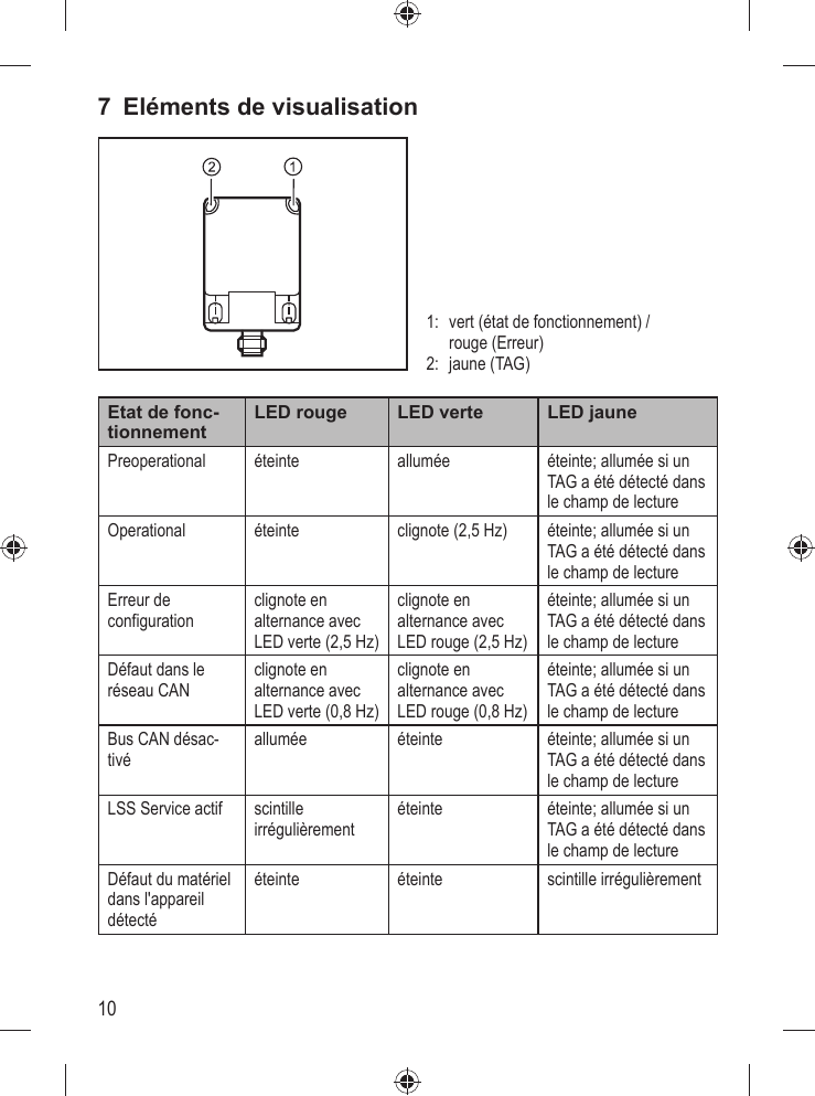
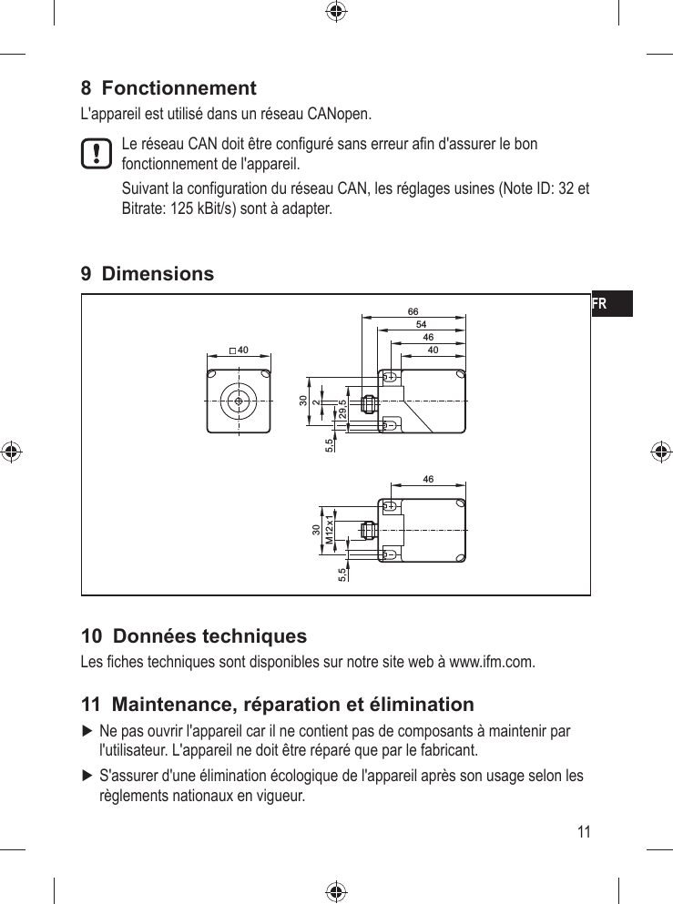
![5FR4.2 AperçuRéférence :Fonction :Désignation :Fréquence de travail :H x L x P [mm] :Puissance d'émission maximale:DTC510tête de lecture/écritureDTCHF MCRWCOUS0313,56 MHz40 x 40 x 54200 mW5 Montage5.1 Instructions de montage généralesEn cas de montage de plusieurs systèmes respecter les distances mini-males entre les têtes de lecture/écriture .Le montage encastré d'une tête de lecture/écriture dans le métal réduit la distance de lecture/écriture. A proximité immédiate des sources d'émission HF, par ex. des transforma-teurs de soudure ou des convertisseurs, le fonctionnement des têtes de lecture/écriture peut être affecté considérablement.Des informations sur les accessoires de montage sont disponibles sur notre site web à www.ifm.com.5.2 Remarques sur le montage des TAGLe montage des TAG en/sur métal réduit la distance lecture/écriture. Pour le positionnement des TAG les têtes de lecture/écriture sont fournies avec un symbole d'antenne sur la face active. Il marque le milieu de la bobine de l'antenne intégrée et doit correspondre au milieu du TAG.L'orientation de l'axe de l'antenne de la tête de lecture/écriture doit corres-pondre à l'axe de la bobine du TAG.](https://usermanual.wiki/ifm-electronic/DTC510R/User-Guide-3414485-Page-29.png)