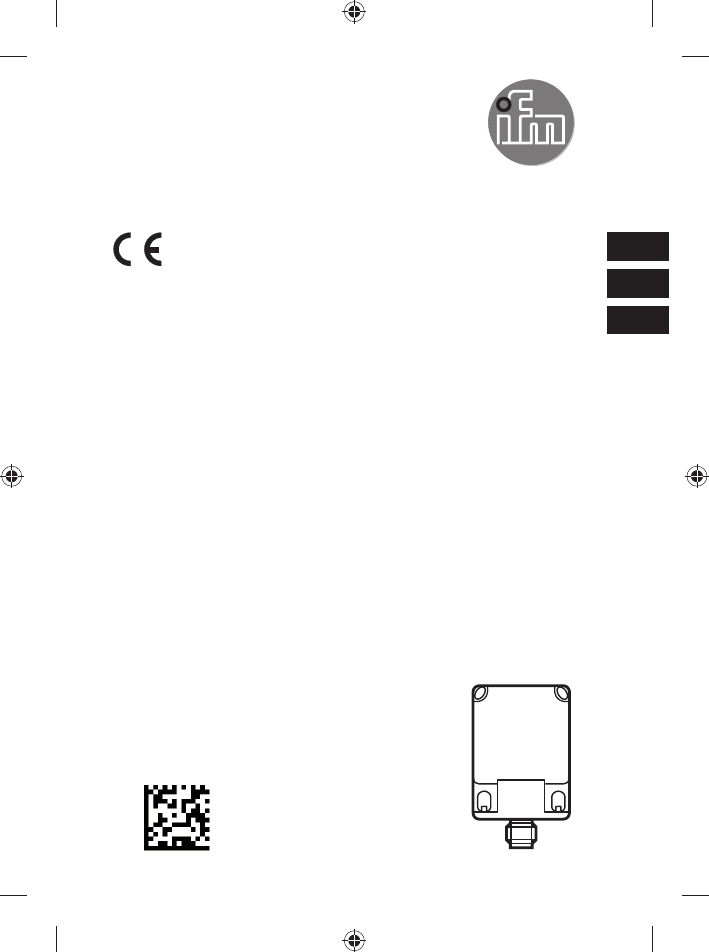
ifm electronic DTC510R RFID read/write head User Manual
ifm electronic gmbh RFID read/write head
Manual
Montageanleitung
RF-Identifikationssystem
Schreib-/Lesekopf
Installation Instructions
RF-identification system
Read/write head
Notice de montage
Système d'identification RFID
Tête de lecture /écriture
DTC510
80259330 / 00 11 / 2016
DE
UK
FR

2
Inhalt
1 Vorbemerkung .....................................................................................................3
1.1 Verwendete Symbole ....................................................................................3
2 Sicherheitshinweise .............................................................................................3
2.1 Allgemein ......................................................................................................3
2.2 Funkanlagen .................................................................................................4
2.3 Störung elektronischer und medizinischer Geräte ........................................4
3 Bestimmungsgemäße Verwendung .....................................................................4
4 Funktion ...............................................................................................................4
4.1 Funktionsweise .............................................................................................4
4.2 Übersicht ......................................................................................................5
5 Montage ...............................................................................................................5
5.1 Generelle Montagehinweise .........................................................................5
5.2 Hinweise zur ID-TAG Montage .....................................................................5
5.3 Vermeidung von Störungen ..........................................................................6
5.4 Mechanischer Aufbau ...................................................................................6
5.5 Aktive Fläche ausrichten ...............................................................................6
5.6 Befestigung ...................................................................................................7
5.7 Montageabstände .........................................................................................7
5.8 Positionierung der ID-TAGs ..........................................................................8
5.9 Ausrichtung der ID-TAGs ..............................................................................8
5.10 ID-TAG Abstände ........................................................................................8
6 Elektrischer Anschluss .........................................................................................9
6.1 Anschlussbelegung .......................................................................................9
6.2 CAN-Bus-Schnittstelle ..................................................................................9
6.3 cULus ...........................................................................................................9
7 Anzeigeelemente ...............................................................................................10
8 Betrieb ............................................................................................................... 11
9 Maße.................................................................................................................. 11
10 Technische Daten ............................................................................................ 11
11 Wartung, Instandsetzung und Entsorgung ....................................................... 11
12 Zulassungen/Normen ......................................................................................12
3
DE
12.1 Funkzulassungen .....................................................................................12
12.1.1 Übersicht ..........................................................................................12
12.1.2 Europa ..............................................................................................12
12.1.3 USA ..................................................................................................12
12.1.4 Kanada .............................................................................................12
12.1.5 Taiwan ..............................................................................................13
12.1.6 Australien ..........................................................................................13
12.1.7 EU-Konformitätserklärung ................................................................13
1 Vorbemerkung
Dieses Dokument ist Bestandteil des Gerätes und enthält Angaben zum korrekten
Umgang mit dem Produkt.
Dieses Dokument richtet sich an Fachkräfte. Dabei handelt es sich um Personen,
die aufgrund ihrer Ausbildung und ihrer Erfahrung befähigt sind, Risiken zu
erkennen und mögliche Gefährdungen zu vermeiden, die der Betrieb oder die
Instandhaltung des Gerätes verursachen kann.
Lesen Sie dieses Dokument vor dem Einsatz, damit Sie mit Einsatzbedingungen,
Installation und Betrieb vertraut werden. Bewahren Sie dieses Dokument während
der gesamten Einsatzdauer des Gerätes auf.
1.1 Verwendete Symbole
►Handlungsanweisung
→Querverweis
Wichtiger Hinweis
Fehlfunktionen oder Störungen sind bei Nichtbeachtung möglich.
Information
Ergänzender Hinweis
2 Sicherheitshinweise
2.1 Allgemein
Befolgen Sie die Angaben dieser Anleitung. Nichtbeachten der Hinweise, Verwen-
dung außerhalb der nachstehend genannten bestimmungsgemäßen Verwendung,
falsche Installation oder Handhabung können Beeinträchtigungen der Sicherheit
von Menschen und Anlagen zur Folge haben.
Der Einbau und Anschluss muss den gültigen nationalen und internationalen Nor-
men entsprechen. Die Verantwortung trägt derjenige, der das Gerät installiert.

4
Das Gerät darf nur von einer Elektrofachkraft eingebaut, angeschlossen und in
Betrieb gesetzt werden, da die sichere Funktion des Gerätes und der Anlage nur
bei ordnungsgemäßer Installation gewährleistet ist.
Schalten Sie das Gerät extern spannungsfrei bevor Sie irgendwelche Arbeiten an
ihm vornehmen.
Bei Fehlfunktion des Gerätes oder bei Unklarheiten bitte mit dem Hersteller in
Verbindung setzen. Eingriffe in das Gerät können schwerwiegende Beeinträchti-
gungen der Sicherheit von Menschen und Anlagen zur Folge haben. Sie sind nicht
zulässig und führen zu Haftungs- und Gewährleistungsauschluss.
2.2 Funkanlagen
Funkgeräte dürfen generell nicht in der Nähe von Tankstellen, Kraftstoffdepots,
Chemiewerken oder Sprengarbeiten benutzt werden.
►Keine entflammbaren Gase, Flüssigkeiten oder explosive Stoffe im Bereich des
Gerätes transportieren und lagern.
2.3 Störung elektronischer und medizinischer Geräte
Der Betrieb kann die Funktionsfähigkeit von nicht ordnungsgemäß geschirmten
elektronischen Geräten beeinträchtigen.
►Das Gerät in der Nähe medizinischer Geräte ausschalten.
►Bei Störungen ggf. beim Hersteller des jeweiligen Gerätes informieren.
3 Bestimmungsgemäße Verwendung
Das Gerät eignet sich zum berührungslosen Lesen und Beschreiben systemkon-
former RFID-Transponder (ID-TAGs).
Die Datenübertragung erfolgt über CAN-Bus.
4 Funktion
4.1 Funktionsweise
Die ID-TAGs werden passiv betrieben, d.h. ohne Batterie. Die zum Betrieb not-
wendige Energie wird vom Lese-/Schreibkopf aufgebracht.
Das physikalische Prinzip der Energieübertragung beruht auf der induktiven
Kopplung. Die integrierte Antennenspule des Lese-/Schreibkopfes erzeugt ein ma-
gnetisches Feld, das zu einem Teil die Antennenspule des ID-TAGs durchdringt.
Durch Induktion wird dort eine Spannung erzeugt die den Datenträger mit Energie
versorgt.
5
DE
4.2 Übersicht
Art.-Nr.:
Funktion:
Typbezeichnung:
Arbeitsfrequenz:
H x B x T [mm]:
Max. Sendeleistung:
DTC510
Lese-/Schreibkopf
DTCHF MCRWCOUS03
13,56 MHz
40 x 40 x 54
200 mW
5 Montage
5.1 Generelle Montagehinweise
Bei der Montage von mehreren Systemen die Mindestabstände zwischen
den Lese-/Schreibköpfen beachten.
Der bündige Einbau eines Lese-/Schreibkopfes in Metall verringert den
Lese-/Schreibabstand.
Die unmittelbare Nähe starker HF-Emissionsquellen, wie z.B. Schweißtra-
fos oder Umformer, kann die Funktion der Lese-/Schreibköpfe beeinträch-
tigen.
Informationen zum erhältlichen Montagezubehör sind im Internet abrufbar unter
www.ifm.com.
5.2 Hinweise zur ID-TAG Montage
Die Montage der ID-TAGs in/auf Metall verringert den Lese-/Schreibab-
stand.
Zur Positionierung der ID-TAGs sind die Lese-/Schreibköpfe auf der aktiven
Fläche mit einem Antennensymbol versehen. Es kennzeichnet die Mitte der
integrierten Antennenspule und muss mit der ID-TAG Mitte übereinstimmen.
Die Ausrichtung der Lese-/Schreibkopf-Antennenachse muss mit der Achse
der ID-TAG Spule übereinstimmen.
6
5.3 Vermeidung von Störungen
Das Gerät erzeugt ein moduliertes elektrisches Feld mit einer Frequenz von
13,56 MHz. Um Störungen der Datenkommunikation zu vermeiden, dürfen in
der Nähe keine anderen Geräte betrieben werden, die in diesem Frequenzband
Störabstrahlungen erzeugen. Zu diesen Geräten gehören beispielsweise Fre-
quenzumrichter und Schaltnetzteile.
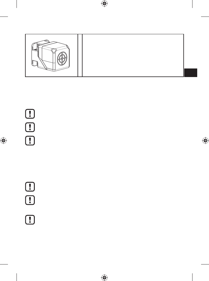
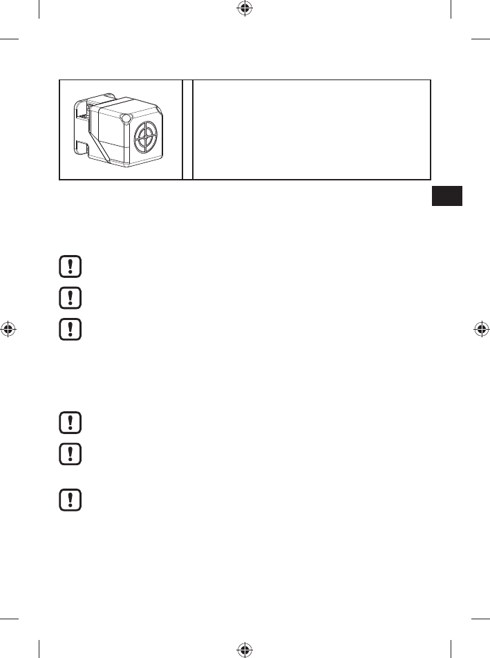
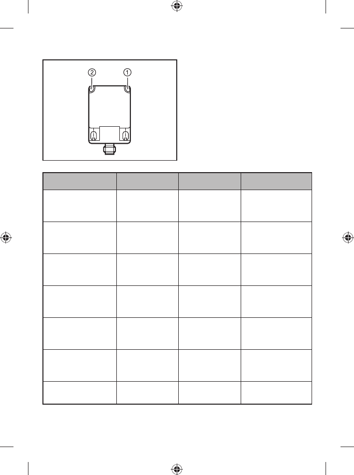
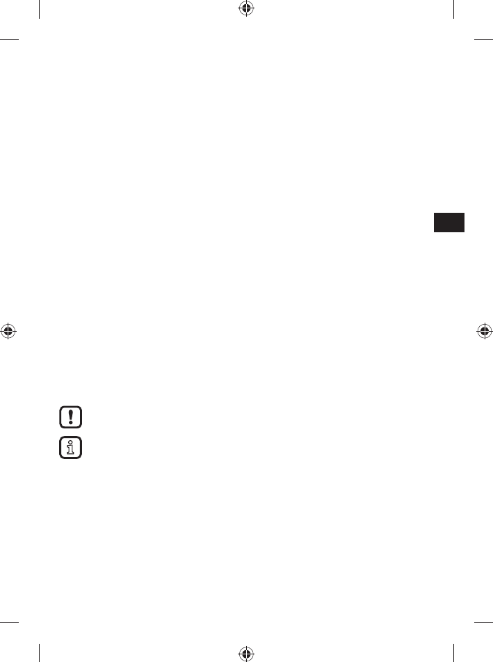
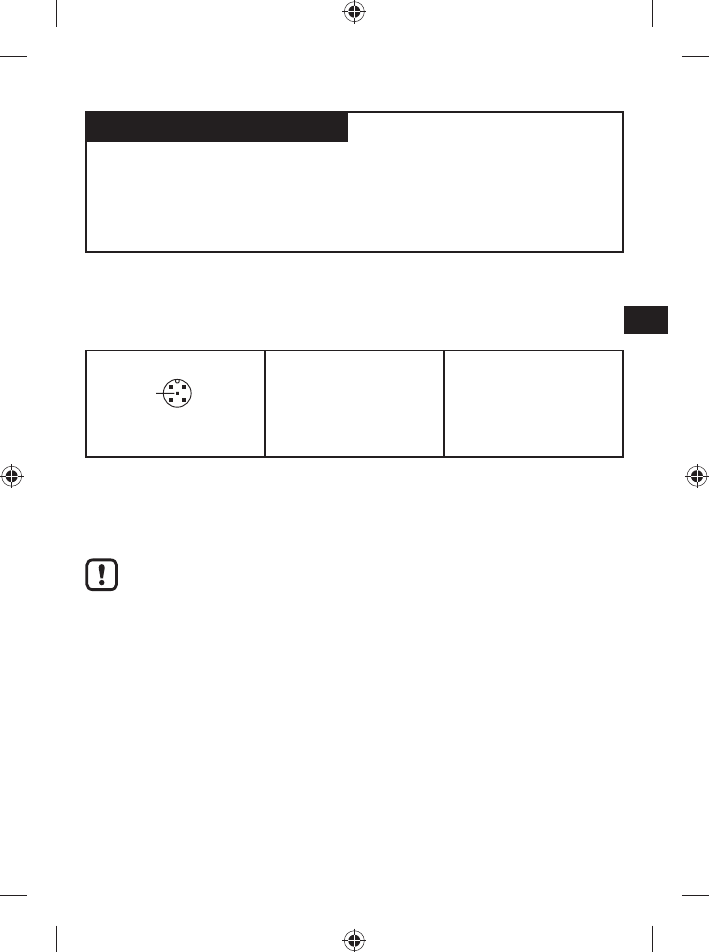
5.4 Mechanischer Aufbau
Die aktive Fläche ist im Lieferzustand nach vorne gerichtet.
2
1
1: Antennenkopf (ausrichtbar)
2: Befestigungselement
Lieferzustand
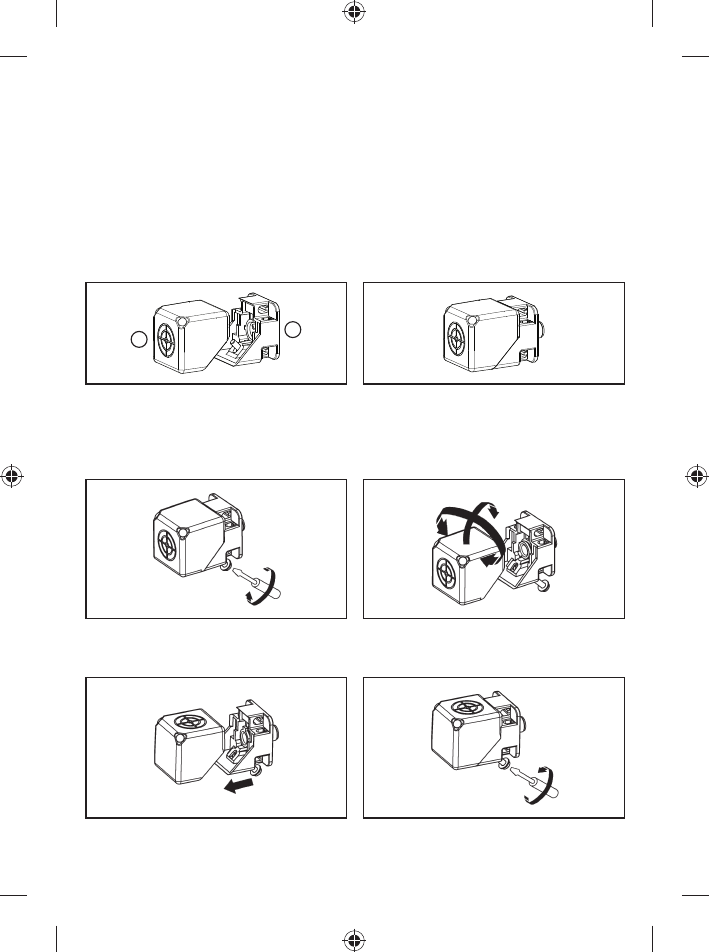
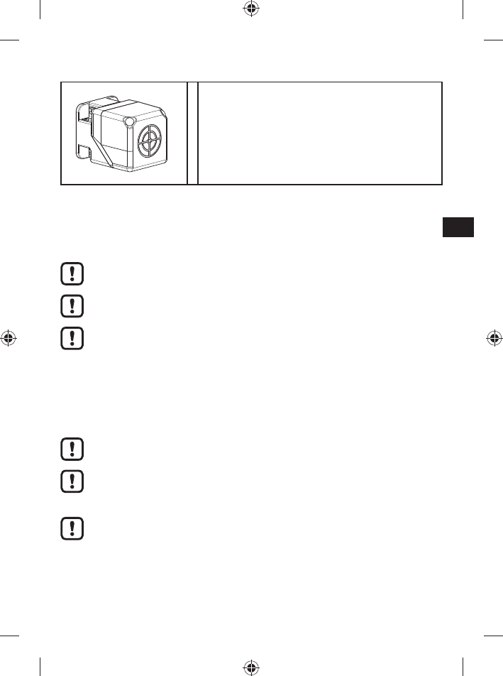
5.5 Aktive Fläche ausrichten
180° 90°
1. Schraube lösen. 2. Antennenkopf vom Befestigungselement
trennen und drehen.
3. Befestigungselement und Antennenkopf
zusammenstecken.
4. Schraube anziehen.
7
DE
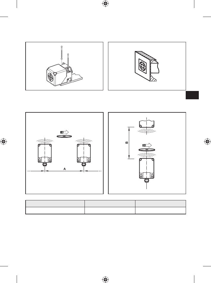
5.6 Befestigung
►Das Gerät mit 2 Stk. M5 Schrauben und Muttern befestigen.
Wahlweise nicht bündig oder bündig.
nicht bündig bündig
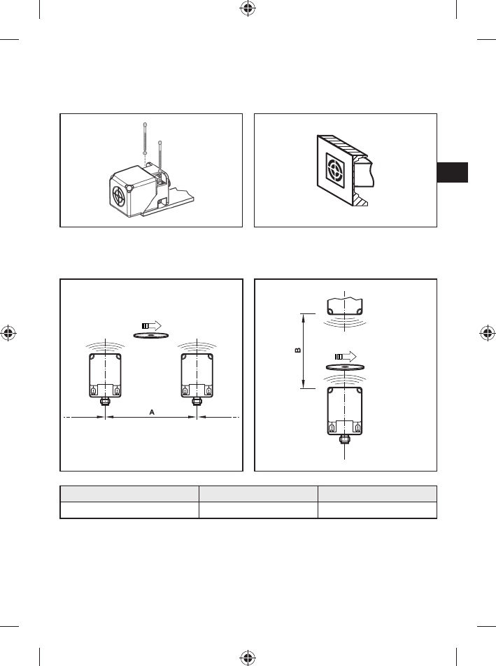
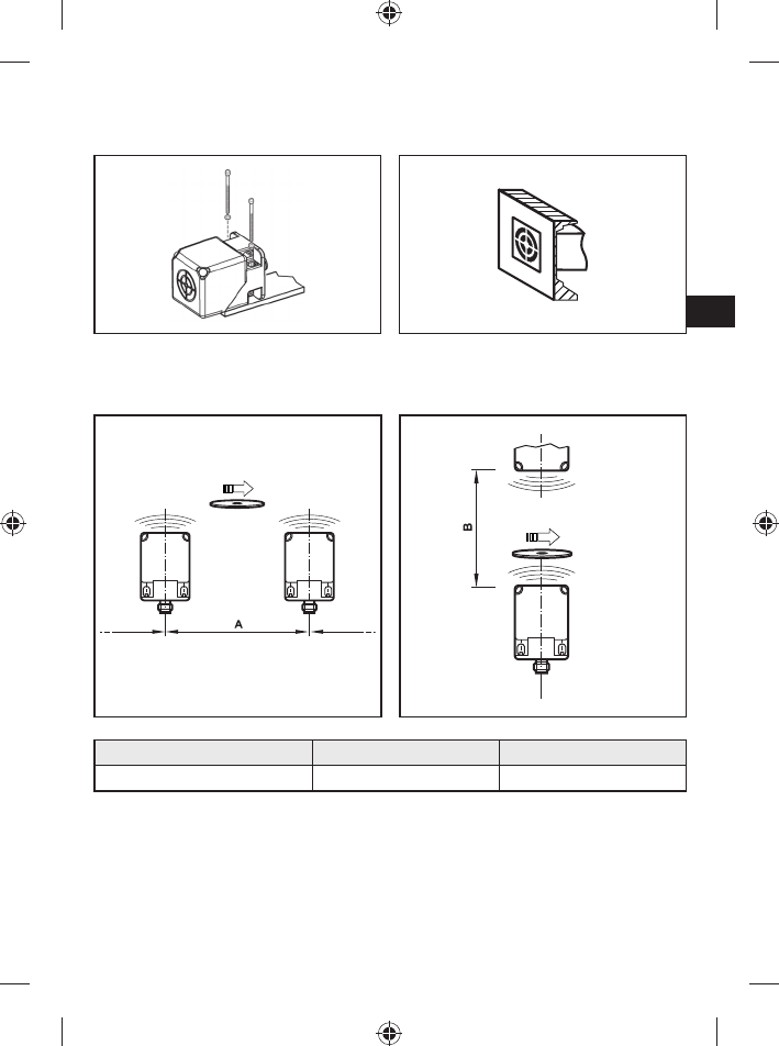
5.7 Montageabstände
Betriebsart Abstand seitlich (A) Abstand frontal (B)
Lesen und Schreiben ≥ 300 mm ≥ 250 mm
8
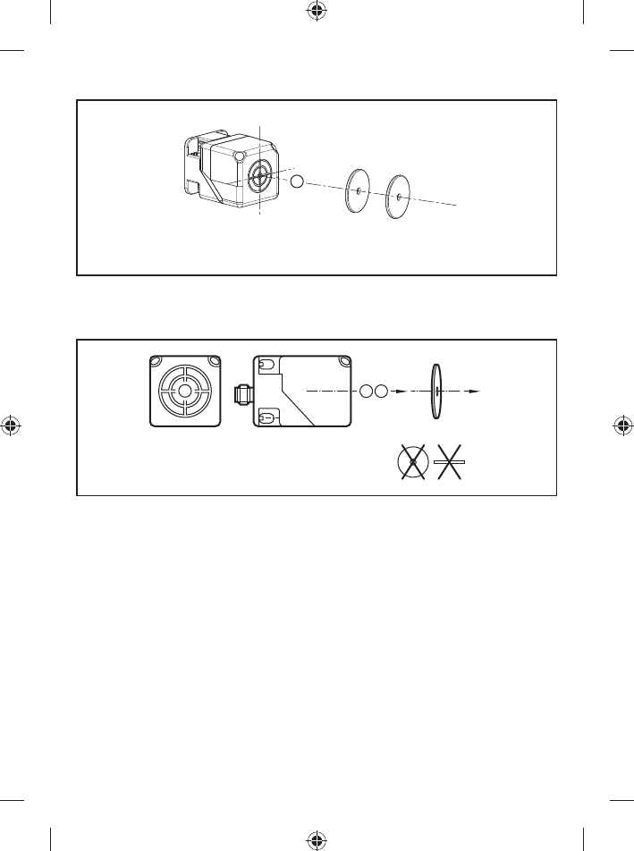
5.8 Positionierung der ID-TAGs
E80370 E80371
1
1: Frontseite
5.9 Ausrichtung der ID-TAGs
21
2
1: Antennenachse DTC510 = Achse ID-TAG
2: Antennenmitte DTC510 = Mitte ID-TAG
5.10 ID-TAG Abstände
Der Abstand zum Referenz ID-TAG E80371 ist im Datenblatt angegeben.
Eine Auswahl an ID-Tags ist im Internet abrufbar unter www.ifm.com.
9
DE
6 Elektrischer Anschluss
ACHTUNG
Das Gerät darf nur von einer Elektrofachkraft installiert werden.
Gerät der Schutzklasse III (SK III)
Die elektrische Versorgung darf nur über PELV-/SELV-Stromkreise erfolgen.
►Stromversorgung vor elektrischen Anschluss spannungsfrei schalten.
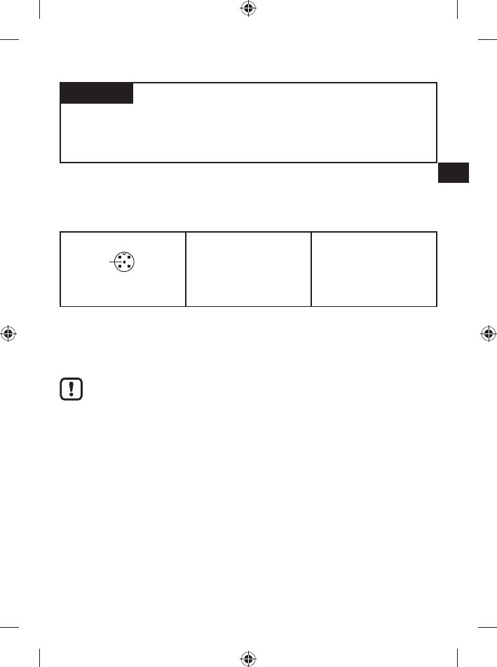
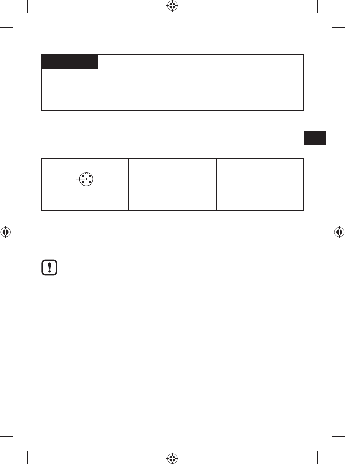
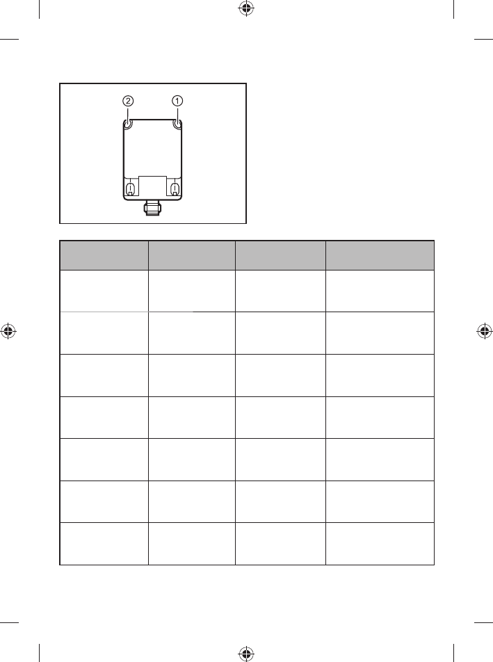
6.1 Anschlussbelegung
Das Gerät ist mit einem 5-poligen Rundstecker M12 (a-kodiert) ausgestattet. Die
Pinbelegung entspricht der CiA DR-303-1.
4
21
3
5
M12-Stecker CAN
1: CAN Abschirmung
2: + UB
3: CAN_GND
4: CAN_H
5: CAN_L
Nicht belegt
Versorgungsspannung
GND
H-Busleitung
L-Busleitung
Eine Auswahl an Kabeldosen ist im Internet abrufbar unter www.ifm.com.
6.2 CAN-Bus-Schnittstelle
Das Gerät verfügt über eine CAN-Schnittstelle.
Verwenden Sie Kabel, die für CAN-Bus freigegeben sind. Terminieren Sie
die Kabel mit Abschlusswiderständen (120 Ω). Verwenden Sie als Variante
das ifm-Kabel EVC492 mit integrierten Abschlusswiderständen.
6.3 cULus
Für Geräte mit cULus-Zulassung und den Gültigkeitsbereich cULus:
►Das Gerät von einer galvanisch getrennten Quelle versorgen, die sekundär
über eine UL-zugelassene Sicherung mit folgendem max. Nennstrom verfügt:
a) 5 A bei Spannungen von 0...20 V rms (0...28,3 V p )
b) 100/V p bei Spannungen von 20...30 V rms (28,3...42,4 V p )
10
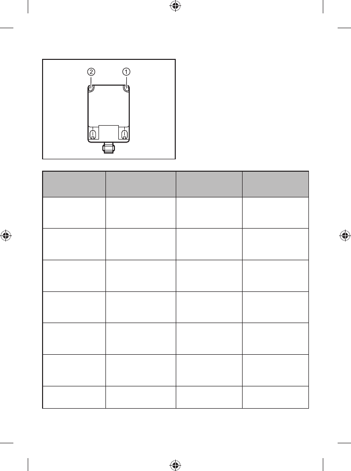
7 Anzeigeelemente
1: grün (Betriebszustand) / rot (Fehler)
2: gelb (ID-TAG)
Betriebs-
zustand
LED rot LED grün LED gelb
Preoperational aus an aus bzw. an wenn
Transponder im
Lesefeld erkannt
Operational aus blinkt (2,5 Hz) aus bzw. an wenn
Transponder im
Lesefeld erkannt
Konfigurations-
fehler
blinkt im Wechsel mit
LED grün (2,5 Hz)
blinkt im Wechsel
mit LED rot (2,5 Hz)
aus bzw. an wenn
Transponder im
Lesefeld erkannt
Fehler im CAN
Netz
blinkt im Wechsel mit
LED grün (0,8 Hz)
blinkt im Wechsel
mit LED rot (0,8 Hz)
aus bzw. an wenn
Transponder im
Lesefeld erkannt
CAN Bus off an aus aus bzw. an wenn
Transponder im
Lesefeld erkannt
LSS Service aktiv flackert unregelmäßig aus aus bzw. an wenn
Transponder im
Lesefeld erkannt
Hardwarefehler im
Gerät erkannt
aus aus flackert unregel-
mäßig
11
DE
8 Betrieb
Das Gerät wird in einem CAN-Netzwerk betrieben.
Das CAN-Netzwerk muss fehlerfrei konfiguriert sein, damit das Gerät
einwandfrei funktioniert.
Je nach Konfiguration des CAN-Netzwerkes müssen die
Werkseinstellungen (Note-ID: 32 und Bitrate: 125 kBit/s) angepasst werden.
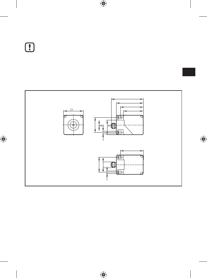
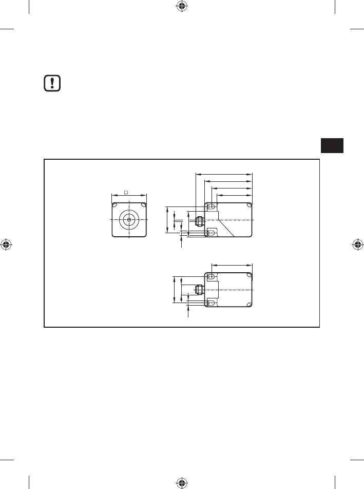
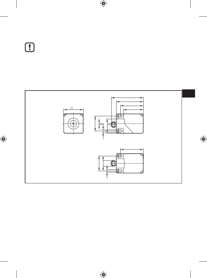
9 Maße
40
66
40
54
M12 x 1
30
30
2
46
46
5,5
5,5 29,5
10 Technische Daten
Die Datenblätter sind im im Internet abrufbar unter www.ifm.com.
11 Wartung, Instandsetzung und Entsorgung
►Da innerhalb des Gerätes keine vom Anwender zu wartenden Bauteile enthal-
ten sind, das Gehäuse nicht öffnen. Die Instandsetzung des Gerätes darf nur
durch den Hersteller durchgeführt werden.
►Das Gerät gemäß den nationalen Umweltvorschriften entsorgen.

12
12 Zulassungen/Normen
12.1 Funkzulassungen
12.1.1 Übersicht
Die Übersicht zum Zulassungsstand eines Gerätes ist im Internet abrufbar unter
www.ifm.com.
12.1.2 Europa
Verwendung in allen EU Staaten
12.1.3 USA
FCC Hinweis:
Dieses Gerät entspricht Teil 15 der FCC-Bestimmungen. Für den Betrieb gelten
die folgenden zwei Bedingungen:
1. Dieses Gerät darf keine schädlichen Störungen verursachen und
2. dieses Gerät muss empfangene Störungen jeglicher Art tolerieren, darunter
auch solche, die den Betrieb beeinträchtigen können.
Änderungen oder Umbauten an diesem Gerät, die nicht ausdrücklich von
ifm genehmigt worden sind, können ein Erlöschen der FFC-Betriebsgenehmigung
zur Folge haben.
HINWEIS: Dieses Gerät wurde getestet und erfüllt die Bestimmungen hinsichtlich
der Beschränkungen für digitale Geräte der Klasse A gemäß Teil 15 der FCC-
Bestimmungen. Diese Beschränkungen dienen dem angemessenen Schutz vor
schädlichen Störungen, wenn das Gerät in gewerblicher Umgebung betrieben
wird. Dieses Gerät erzeugt und verwendet Hochfrequenzenergie und kann diese
ausstrahlen. Wird das Gerät nicht gemäß der Bedienungsanleitung installiert und
verwendet, kann dies zu schädlichen Störungen des Funkverkehrs führen. Wird
das Gerät in einem Wohngebiet betrieben, kann dies zu schädlichen Störungen
führen, die der Anwender auf eigene Kosten beseitigen muss.
12.1.4 Kanada
IC Hinweis:
Dieses Gerät erfüllt die lizenzfreien Industry Canada RSS-Standards.
Für den Betrieb gelten die folgenden zwei Bedingungen:
1. das Gerät darf keine schädlichen Störungen verursachen, und
2. der Benutzer des Geräts muss empfangene Störungen jeglicher Art tolerieren,
darunter auch solche, die den Betrieb beeinträchtigen können.
13
DE
12.1.5 Taiwan
Rechtsvorschriften zu leistungsarmen Funkwellengeräten
Artikel 12
Sofern keine Genehmigung durch NCC vorliegt darf kein Unternehmen
oder Benutzer die Frequenz ändern, die Sendeleistung erhöhen oder die
ursprünglichen Konstruktionsmerkmale oder Betriebsfunktionen eines
zugelassenen leistungsarmen Funkfrequenzgerätes verändern.
Artikel 14
Leistungsarme Funkfrequenzgeräte dürfen weder die Flugsicherheit
beeinträchtigen noch legale Kommunikation stören. Falls solche Störungen
auftreten muss der Benutzer sofort den Betrieb des Gerätes einstellen, bis eine
Verbesserung eintritt und die Störung nicht mehr auftritt.
Legale Kommunikation bedeutet Funkkommunikationsbetrieb in Übereinstimmung
mit dem Telecommunications Act. Leistungsarme Funkfrequenzgeräte müssen
jegliche im Rahmen von legaler Kommunikation und von ISM-Funkgeräten
empfangenen Störungen akzeptieren.
12.1.6 Australien
Verwendung in Australien:
12.1.7 EU-Konformitätserklärung
Hiermit erklärt die ifm electronic GmbH, dass der Funkanlagentyp DTC510 der
Richtlinie 2014/53/EU entspricht.
Der vollständige Text der EU-Konformitätserklärung ist unter der folgenden
Internetadresse verfügbar: www.ifm.com.

2
Contents
1 Preliminary note ...................................................................................................3
1.1 Symbols used ...............................................................................................3
2 Safety instructions ...............................................................................................3
2.1 General .........................................................................................................3
2.2 Radio equipment ..........................................................................................4
2.3 Interference of electronic and medical devices ............................................4
3 Functions and features ........................................................................................4
4 Functions .............................................................................................................4
4.1 Operating principle .......................................................................................4
4.2 Overview .......................................................................................................5
5 Installation............................................................................................................5
5.1 General installation instructions ....................................................................5
5.2 Notes on ID tag mounting .............................................................................5
5.3 Avoiding interference ....................................................................................6
5.4 Mechanical design ........................................................................................6
5.5 Alignment of the sensing face .......................................................................6
5.6 Fixing ............................................................................................................7
5.7 Mounting distances .......................................................................................7
5.8 Positioning of the ID tags ..............................................................................8
5.9 Orientation of the ID tags ..............................................................................8
5.10 ID tag distances ..........................................................................................8
6 Electrical connection ............................................................................................9
6.1 Wiring ...........................................................................................................9
6.2 CAN bus interface ........................................................................................9
6.3 cULus ...........................................................................................................9
7 Display elements ...............................................................................................10
8 Operation ........................................................................................................... 11
9 Dimensions ........................................................................................................ 11
10 Technical data .................................................................................................. 11
11 Maintenance, repair and disposal .................................................................... 11
12 Approvals/standards ........................................................................................12
3
UK
12.1 Radio approvals ........................................................................................12
12.1.1 Overview ...........................................................................................12
12.1.2 Europe ..............................................................................................12
12.1.3 USA ..................................................................................................12
12.1.4 Canada .............................................................................................12
12.1.5 Taiwan ..............................................................................................13
12.1.6 Australia ............................................................................................13
12.1.7 EC declaration of conformity ............................................................13
1 Preliminary note
This document is part of the device and contains information about the correct
handling of the product.
This document is intended for specialists. These specialists are people who are
qualified by their training and their experience to see risks and to avoid possible
hazards that may be caused during operation or maintenance of the device.
Read this document before use to familiarise yourself with operating conditions,
installation and operation. Keep this document during the entire duration of use of
the device.
1.1 Symbols used
►Instructions
→Cross-reference
Important note
Non-compliance can result in malfunction or interference.
Information
Supplementary note
2 Safety instructions
2.1 General
Observe the operating instructions. Non-observance of the instructions, operation
which is not in accordance with use as prescribed below, wrong installation or
incorrect handling can affect the safety of operators and machinery.
The installation and connection must comply with the applicable national and
international standards. Responsibility lies with the person installing the device.

4
The device must only be installed, connected and put into operation by a qualified
electrician as the safe function of the device and machinery is only guaranteed
when installation is correctly carried out.
Disconnect the unit externally before handling it.
In case of malfunction of the device or uncertainties please contact the
manufacturer. Tampering with the device can seriously affect the safety of
operators and machinery. This is not permitted and leads to an exclusion of liability
and warranty.
2.2 Radio equipment
In general, radio equipment must not be used in the vicinity of petrol stations, fuel
depots, chemical plants or blasting operations.
►Do not transport and store any flammable gases, liquids or explosive
substances near the unit.
2.3 Interference of electronic and medical devices
Operation can affect the function of electronic devices that are not correctly
shielded.
►Disconnect the device in the vicinity of medical equipment.
►Contact the manufacturer of the corresponding device in case of any
interference.
3 Functions and features
The device is suited for non-contact reading and writing of system-compliant RFID
tags (ID tags).
Data transmission is done via the CAN bus.
4 Functions
4.1 Operating principle
The ID tags are operated passively, i.e. without battery. The energy required for
operation is supplied by the read/write head.The physical principle of the energy
transfer is based on inductive coupling. The integrated antenna coil in the read/
write head generates a magnetic field which partly penetrates the antenna coil of
the ID tag. A voltage is generated by induction that supplies the data carrier with
energy.
5
UK
4.2 Overview
Art. no.:
Function:
Type designation:
operating frequency:
H X W X D [mm]:
Max. transmission power:
DTC510
read/write head
DTCHF MCRWCOUS03
13.56MHz
40 x 40 x 54
200 mW
5 Installation
5.1 General installation instructions
When mounting several read/write heads adhere to the minimum distances
between the systems.
Flush mounting of a read/write head in metal reduces the read/write dis-
tance.
The immediate vicinity of powerful HF emission sources such as welding
transformers or converters can affect operation of the read/write heads.
Information on the available mounting accessories is available on our website at
www.ifm.com.
5.2 Notes on ID tag mounting
If the ID tags are mounted in/on metal, the read/write distance is reduced.
For positioning the ID tags the read/write heads are marked with an an-
tenna symbol on the active face. It designates the middle of the integrated
antenna coil and has to correspond with the middle of the ID tag.
The orientation of the read/write head antenna axis must correspond with
the axis of the ID tag coil.

6
5.3 Avoiding interference
The device generated a modulated electrical field with a frequency of 13.56 kHz.
To avoid interference of the data communication no other devices generating
interference emission in this frequency band must be operated in the vicinity. Such
devices are for example frequency converters and switched-mode power supplies.
5.4 Mechanical design
On delivery the sensing face is facing the front.
2
1
1: Antenna head (can be aligned)
2: Fixing element
Factory setting
5.5 Alignment of the sensing face
180° 90°
1. Loosen the screw. 2. Remove the antenna head from the fixing
element and turn it.
3. Attach the fixing element to the antenna
head.
4. Tighten the screw.
7
UK
5.6 Fixing
►The device is fixed with 2 M5 screws and nuts. Order non flush or flush.
non flush flush
5.7 Mounting distances
Operating mode Distance side (A) Distance front (B)
For reading and writing ≥ 300 mm ≥ 250 mm

8
5.8 Positioning of the ID tags
E80370 E80371
1
1: front side
5.9 Orientation of the ID tags
21
2
1: antenna axis DTC510 = ID tag axis
2: middle of the antenna ATN513x = middle of the ID tag
5.10 ID tag distances
The distance to the E80371 reference ID tag is indicated in the data sheet.
A selection of ID tags is available on our website at www.ifm.com.
9
UK
6 Electrical connection
ATTENTION
The unit must be connected by a qualified electrician.
Device of protection class III (PC III)
The electric supply must only be made via PELV/SELV circuits.
►Disconnect power before connecting the unit.
6.1 Wiring
The device has a 5-pole round M12 connector (A-coded). The pin connection
corresponds to CiA DR-303-1.
4
21
3
5
M12 connector CAN
1: CAN shield
2: + UB
3: CAN _GND
4: CAN_H
5: CAN_L
Not connected
Supply voltage
GND
H bus cable
L bus cable
A selection of sockets is available on our website at www.ifm.com.
6.2 CAN bus interface
The device has a CAN interface.
Use cables that are approved for CAN bus. Terminate the cables using
terminating resistors (120 Ω). Use ifm's EVC492 cable with integrated
terminating resistor as an alternative.
6.3 cULus
For units with cULus approval and the scope of validity cULus:
►Supply the device from an isolating transformer having a secondary UL-listed
fuse rated
a) 5 A at voltages of 0...20 V rms (0...28.3 V p )
b) 100/V p at voltages of 20...30 V rms (28.3...42.4 V p )
10
7 Display elements
1: green (operating status) / red (Error)
2: yellow (ID-tag)
Operating status LED red LED green LED yellow
Preoperational off on off; on if a tag has
been detected in the
reading field
Operational off flashes (2.5 Hz) off; on if a tag has
been detected in the
reading field
Configuration error flashes alternately
with green LED
(2.5 Hz)
flashes alternately
with red LED (2.5
Hz)
off; on if a tag has
been detected in the
reading field
Error in the CAN
network
flashes alternately
with green LED
(0.8 Hz)
flashes alternately
with red LED (0.8
Hz)
off; on if a tag has
been detected in the
reading field
CAN bus off on off off; on if a tag has
been detected in the
reading field
LSS service active flickers irregularly off off; on if a tag has
been detected in the
reading field
Hardware error
detected in the device
off off flickers irregularly
11
UK
8 Operation
The device is operated in a CANopen network.
The CAN network must be correctly configured so that the device functions
reliably.
Depending on the configuration of the CAN network the factory settings
(Note ID: 32 and bit rate: 125 kBit/s) have to be adapted.
9 Dimensions
40
66
40
54
M12 x 1
30
30
2
46
46
5,5
5,5 29,5
10 Technical data
The data sheets are available on our website at www.ifm.com.
11 Maintenance, repair and disposal
►Do not open the housing as the device does not contain any components
which must be maintained by the user. The device must only be repaired by the
manufacturer.

12
►Dispose of the device in accordance with the national environmental
regulations.
12 Approvals/standards
12.1 Radio approvals
12.1.1 Overview
The overview of the approval status of a unit is available on our website at www.
ifm.com.
12.1.2 Europe
Use in all EU countries
12.1.3 USA
FCC note:
This device complies with Part 15 of the FCC Rules. Operation is subject to the
following two conditions:
1. This device must not cause harmful interference, and
2. this device must accept any interference received, including interference that
may cause undesired operation.
Changes or modifications made to this equipment not expressly approved by ifm
may void the FCC authorization to operate this equipment.
NOTE: This equipment has been tested and found to comply with the limits for
a Class A digital device, pursuant to part 15 of the FCC Rules. These limits are
designed to provide reasonable protection against harmful interference when the
equipment is operated in a commercial environment. This equipment generates,
uses and can radiate radio frequency energy and, if not installed and used
in accordance with the instructions, may cause harmful interference to radio
communications. Operation of this equipment in a residential area is likely to
cause harmful interference in which case the user will be required to correct the
interference at his own expense.
12.1.4 Canada
IC note:
This device complies with Industry Canada license-exempt RSS standards.
Operation is subject to the following two conditions:
1. The device may not cause interference, and
13
UK
2. the user of the device must accept any interference received, including
interference that may cause undesired operation.
12.1.5 Taiwan
Administrative Regulations on Low Power Radio Wave Devices warning
Article 12
Unless granted permission by NCC, no company, firm, or user shall alter
the frequency, increase the transmitting power, or alter the original design
characteristics or operating functions of an approved low-power radio-frequency
device.
Article 14
Low-power radio-frequency devices shall not affect aircraft security nor interfere
with legal communications. If such interference occurs, the user shall immediately
cease operating the device until improvement is made and the interference no
longer exists.
Legal communications refers to the wireless telecommunication operations that
comply with the Telecommunications Act. Low-power radio-frequency devices
must accept any interference received from legal communications and ISM radio
wave devices.
12.1.6 Australia
Use in Australia:
12.1.7 EC declaration of conformity
ifm electronic gmbh hereby declares that the DTC510 radio system corresponds
to the directive 2014/53/EU.
You can find the EC declaration of conformity on our website at: www.ifm.com.

2
Contenu
1 Remarque préliminaire ........................................................................................3
1.1 Symboles utilisés ..........................................................................................3
2 Consignes de sécurité .........................................................................................3
2.1 Général .........................................................................................................3
2.2 Equipements radio ........................................................................................4
2.3 Perturbations d'appareils électroniques et médicaux ...................................4
3 Fonctionnement et caractéristiques .....................................................................4
4 Fonction ...............................................................................................................4
4.1 Principe de fonctionnement ..........................................................................4
4.2 Aperçu ..........................................................................................................5
5 Montage ...............................................................................................................5
5.1 Instructions de montage générales ..............................................................5
5.2 Remarques sur le montage des TAG ...........................................................5
5.3 Elimination de parasites ...............................................................................6
5.4 Conception mécanique .................................................................................6
5.5 Orientation de la face active .........................................................................6
5.6 Fixation .........................................................................................................7
5.7 Distances de montage ..................................................................................7
5.8 Positionnement des TAG ..............................................................................8
5.9 Orientation des TAG .....................................................................................8
5.10 Distances TAG ............................................................................................8
6 Raccordement électrique .....................................................................................9
6.1 Schéma de branchement .............................................................................9
6.2 Interface bus CAN ........................................................................................9
6.3 cULus ...........................................................................................................9
7 Eléments de visualisation ..................................................................................10
8 Fonctionnement ................................................................................................. 11
9 Dimensions ........................................................................................................ 11
10 Données techniques ........................................................................................ 11
11 Maintenance, réparation et élimination ............................................................ 11
12 Homologations/normes ....................................................................................12
3
FR
12.1 Homologations radio .................................................................................12
12.1.1 Aperçu ..............................................................................................12
12.1.2 Europe ..............................................................................................12
12.1.3 États-Unis .........................................................................................12
12.1.4 Canada .............................................................................................12
12.1.5 Taiwan ..............................................................................................13
12.1.6 Australie ............................................................................................13
12.1.7 Déclaration de conformité CE ...........................................................13
1 Remarque préliminaire
Ce document fait partie de l'appareil et fournit des informations sur l'utilisation
correcte du produit.
Ce document s'adresse à des personnes compétentes. Ce sont des personnes
qui sont capables - grâce à leur formation et expérience – d’apercevoir des
risques et d'éviter des dangers potentiels qui pourraient être causés par le fonc-
tionnement ou la maintenance de l'appareil.
Lire ce document avant l'utilisation afin de vous familiariser avec les conditions
environnantes, l'installation et le fonctionnement. Garder ce document pendant
tout le temps d'emploi de l'appareil.
1.1 Symboles utilisés
►Action à faire
→Référence
Remarque importante
Le non-respect peut aboutir à des dysfonctionnements ou perturbations.
Information
Remarque supplémentaire.
2 Consignes de sécurité
2.1 Général
Respecter les indications de cette notice. Le non-respect des consignes, l'emploi
non conforme par rapport aux prescriptions, un montage ou une manipulation
incorrect peuvent porter atteinte à la sécurité des personnes et des installations.
Le montage et le raccordement doivent être conformes aux normes nationales et
internationales en vigueur. La personne qui installe l'appareil en est responsable.

4
L'appareil doit être monté, raccordé et mis en service par un électricien qualifié
car seul un montage correct garantit le bon fonctionnement de l'appareil et de
l'installation.
Mettre l'appareil hors tension en externe avant toute manipulation.
En cas de mauvais fonctionnement de l'appareil ou en cas de doute contacter le
fabricant. Les interventions sur l'appareil peuvent avoir des conséquences graves
pour la sécurité des personnes et des installations. Elles ne sont pas autorisées et
conduisent à une exclusion de responsabilité et de garantie.
2.2 Equipements radio
En général, les équipements radio ne doivent pas être utilisés à proximité de
stations d'essence, de dépôts de carburants, d'usines chimiques ou de lieux où il
existe des risques de détonation.
►Ne pas transporter et stocker de gaz, liquides inflammables ou de substances
explosives près de l'appareil.
2.3 Perturbations d'appareils électroniques et médicaux
L'emploi de l'appareil peut affecter le bon fonctionnement des appareils électro-
niques qui ne sont pas correctement blindés.
►Mettre l'appareil hors tension à proximité des équipements médicaux.
►En cas de problèmes, contacter le fabricant de l'appareil correspondant.
3 Fonctionnement et caractéristiques
L'appareil est utilisé pour lire et/ou écrire sans contact des étiquettes électro-
niques RFID (TAG) compatibles avec le système.
La transmission des données s'effectue via le bus CAN.
4 Fonction
4.1 Principe de fonctionnement
Les TAG sont passifs, l'énergie nécessaire à leur fonctionnement étant fournie par
la tête de lecture/écriture.Le principe physique du transfert de l'énergie repose sur
le couplage inductif. La bobine de l'antenne intégrée dans la tête de lecture/écri-
ture génère un champ magnétique qui pénètre en partie la bobine de l'antenne du
TAG. Une tension est générée par induction qui alimente le support de données
en énergie.
5
FR
4.2 Aperçu
Référence :
Fonction :
Désignation :
Fréquence de travail :
H x L x P [mm] :
Puissance d'émission
maximale:
DTC510
tête de lecture/écriture
DTCHF MCRWCOUS03
13,56 MHz
40 x 40 x 54
200 mW
5 Montage
5.1 Instructions de montage générales
En cas de montage de plusieurs systèmes respecter les distances mini-
males entre les têtes de lecture/écriture .
Le montage encastré d'une tête de lecture/écriture dans le métal réduit la
distance de lecture/écriture.
A proximité immédiate des sources d'émission HF, par ex. des transforma-
teurs de soudure ou des convertisseurs, le fonctionnement des têtes de
lecture/écriture peut être affecté considérablement.
Des informations sur les accessoires de montage sont disponibles sur notre site
web à www.ifm.com.
5.2 Remarques sur le montage des TAG
Le montage des TAG en/sur métal réduit la distance lecture/écriture.
Pour le positionnement des TAG les têtes de lecture/écriture sont fournies
avec un symbole d'antenne sur la face active. Il marque le milieu de la
bobine de l'antenne intégrée et doit correspondre au milieu du TAG.
L'orientation de l'axe de l'antenne de la tête de lecture/écriture doit corres-
pondre à l'axe de la bobine du TAG.

6
5.3 Elimination de parasites
L'appareil génère un champ électrique modulé avec une fréquence de 13,56 kHz.
Pour éviter des perturbations de la communication de données, il n'est pas permis
de faire fonctionner d'autres appareils à proximité s'ils génèrent des émissions
de rayonnements HF dans cette bande de fréquences, comme par exemple des
variateurs de fréquence et des alimentations à découpage.
5.4 Conception mécanique
A la livraison, la face active est orientée vers l'avant.
2
1
1: tête d'antenne (orientable)
2: accessoire de fi xation
A la livraison
5.5 Orientation de la face active
180° 90°
1. Desserrer la vis. 2. Séparer la tête d'antenne de l'accessoire
de fixation et la tourner.
3. Placer l'accessoire de fixation sur la tête
d'antenne.
4. Serrer la vis.
7
FR
5.6 Fixation
►Fixer l'appareil à l'aide de 2 vis M5 et écrous. Au choix encastré ou non.
non encastré encastré
5.7 Distances de montage
Mode de fonctionnement Distance latérale (A) Distance frontale (B)
Lecture et écriture ≥ 300 mm ≥ 250 mm

8
5.8 Positionnement des TAG
E80370 E80371
1
1: face avant
5.9 Orientation des TAG
21
2
1: axe de l'antenne DTC510 = axe du TAG
2: milieu de l'antenne DTC510 = milieu du TAG
5.10 Distances TAG
La distance au TAG de référence E80371 est indiquée dans la fiche technique.
Une sélection de TAG est disponible sur notre site web à www.ifm.com.
9
FR
6 Raccordement électrique
INFORMATION IMPORTANTE
L'appareil doit être raccordé par un électricien qualifié.
Appareil de la classe de protection III (CP III)
L'alimentation électrique ne doit s'effectuer que via des circuits TBTP / TBTS.
►Avant le raccordement électrique mettre l'installation hors tension.
6.1 Schéma de branchement
L'appareil est équipé d'un connecteur M12 5 pôles (codage A). Le raccordement
des broches correspond à CiA DR-303-1.
4
21
3
5
Connecteur M12 CAN
1: Blindage CAN
2: + UB
3: CAN GND
4: CAN_H
5: CAN_L
Non raccordé
Tension d'alimentation
GND
Câble bus H
Câble bus L
Une sélection de connecteurs femelles est disponible sur Internet www.ifm.com.
6.2 Interface bus CAN
L'appareil dispose d'une interface CAN.
Utiliser des câbles homologués pour le bus CAN. Terminer les câbles avec
des résistances de terminaison (120 Ω). Comme variante utiliser le câble
EVC492 d'ifm avec des résistances de terminaison intégrées.
6.3 cULus
Pour des appareils avec homologation cULus et le champ d'application cULus :
►Alimenter l'appareil via une source isolée galvaniquement disposant au secon-
daire d'un fusible avec homologation UL et le courant nominal max. suivant :
a) 5 A pour des tensions de 0...20 V rms (0...28,3 V p )
b) 100/V p pour des tensions de 20...30 V rms (28,3...42,4 V p )
10
7 Eléments de visualisation
1: vert (état de fonctionnement) /
rouge (Erreur)
2: jaune (TAG)
Etat de fonc-
tionnement
LED rouge LED verte LED jaune
Preoperational éteinte allumée éteinte; allumée si un
TAG a été détecté dans
le champ de lecture
Operational éteinte clignote (2,5 Hz) éteinte; allumée si un
TAG a été détecté dans
le champ de lecture
Erreur de
configuration
clignote en
alternance avec
LED verte (2,5 Hz)
clignote en
alternance avec
LED rouge (2,5 Hz)
éteinte; allumée si un
TAG a été détecté dans
le champ de lecture
Défaut dans le
réseau CAN
clignote en
alternance avec
LED verte (0,8 Hz)
clignote en
alternance avec
LED rouge (0,8 Hz)
éteinte; allumée si un
TAG a été détecté dans
le champ de lecture
Bus CAN désac-
tivé
allumée éteinte éteinte; allumée si un
TAG a été détecté dans
le champ de lecture
LSS Service actif scintille
irrégulièrement
éteinte éteinte; allumée si un
TAG a été détecté dans
le champ de lecture
Défaut du matériel
dans l'appareil
détecté
éteinte éteinte scintille irrégulièrement
11
FR
8 Fonctionnement
L'appareil est utilisé dans un réseau CANopen.
Le réseau CAN doit être configuré sans erreur afin d'assurer le bon
fonctionnement de l'appareil.
Suivant la configuration du réseau CAN, les réglages usines (Note ID: 32 et
Bitrate: 125 kBit/s) sont à adapter.
9 Dimensions
40
66
40
54
M12 x 1
30
30
2
46
46
5,5
5,5 29,5
10 Données techniques
Les fiches techniques sont disponibles sur notre site web à www.ifm.com.
11 Maintenance, réparation et élimination
►Ne pas ouvrir l'appareil car il ne contient pas de composants à maintenir par
l'utilisateur. L'appareil ne doit être réparé que par le fabricant.
►S'assurer d'une élimination écologique de l'appareil après son usage selon les
règlements nationaux en vigueur.

12
12 Homologations/normes
12.1 Homologations radio
12.1.1 Aperçu
L'aperçu de l'état d'homologation d'un appareil est disponible sur Internet :
www.ifm.com.
12.1.2 Europe
utilisation dans tous les états de l'UE
12.1.3 États-Unis
Note FCC :
Cet appareil est conforme à la Partie 15 de la réglementation de la FCC
(Commission Fédérale des Communications). L'exploitation est autorisée aux
deux conditions suivantes:
1. Cet appareil ne doit pas provoquer d'interférences nuisibles, et
2. cet appareil doit accepter toute interférence reçue, y compris des interférences
susceptibles de provoquer un fonctionnement non désiré.
Tout changement ou modification non expressément approuvé par la partie
responsable des mesures de conformité peut amener l'utilisateur à se voir
interdire l'usage de l'appareil.
NOTE : Cet appareil a été testé et satisfait aux limites imposées aux appareils
numériques de la classe A conformément à la partie 15 de la réglementation
FCC. Ces limites sont destinées à fournir une protection raisonnable contre
toute interférence nuisible dans un environnement commercial. Cet équipement
génère, utilise et peut émettre des radiofréquences. S'il n'est pas installé et utilisé
conformément aux instructions, il peut provoquer des interférences nuisibles aux
radiocommunications. L'utilisation de cet appareil dans une zone résidentielle peut
provoquer des interférences nuisibles que l'utilisateur devra corriger à ses frais.
12.1.4 Canada
Note IC :
Cet appareil est conforme aux normes RSS exemptes de licence de la
réglementation d'Industrie Canada.
Son utilisation est sujette aux deux conditions suivantes :
1. cet appareil ne doit pas provoquer d'interférences nuisibles, et
13
FR
2. ce dispositif doit accepter tout brouillage reçu, y compris un brouillage
susceptible de provoquer un fonctionnement indésirable.
12.1.5 Taiwan
Mise en garde concernant le règlement administratif sur les appareils de
faible puissance émettant des ondes radio
Article 12
En l’absence d’autorisation de la NCC, aucune société, entreprise ou utilisateur
ne doit modifier la fréquence, augmenter la puissance de transmission ou modifier
les caractéristiques d’origine ainsi que les fonctions de tout appareil approuvé à
fréquences radio de faible puissance.
Article 14
Les appareils à fréquences radio de faible puissance ne doivent pas interférer
avec les systèmes de communication aéronautiques et les communications
légales. Au cas où des interférences seraient constatées, l’utilisateur doit cesser
l’utilisation immédiatement jusqu'à ce qu'une amélioration soit apportée et que
l'interférence ne soit plus présente.
Les communications légales mentionnées se rapportant aux communications
respectant les lois et règlements portants sur les télécommunications.
L’équipement électrique de faible puissance émettant des ondes radio doit tolérer
toute interférence reçue d’équipements de communications légales ou d’appareils
à ondes radio ISM.
12.1.6 Australie
Utilisation en Australie :
12.1.7 Déclaration de conformité CE
ifm electronic gmbh déclare par la présente que l'équipement radio DTC510
correspond à la directive 2014/53/EU.
La déclaration de conformité CE est disponible sur Internet : www.ifm.com.