ifm electronic DTS125-AA RFID Reader User Manual DTA100
ifm electronic gmbh RFID Reader DTA100
UserManual.wiki
>
ifm electronic
>
DTS125-AA User Manual
>
User Manual DTA100
Contents
1.
User Manual DTA100
2.
User Manual DTA101
User Manual DTA100
Navigation menu
Upload a User Manual
Namespaces
Wiki Guide
HTML
PDF
Info
Views
User Manual
Discussion / Help
Navigation
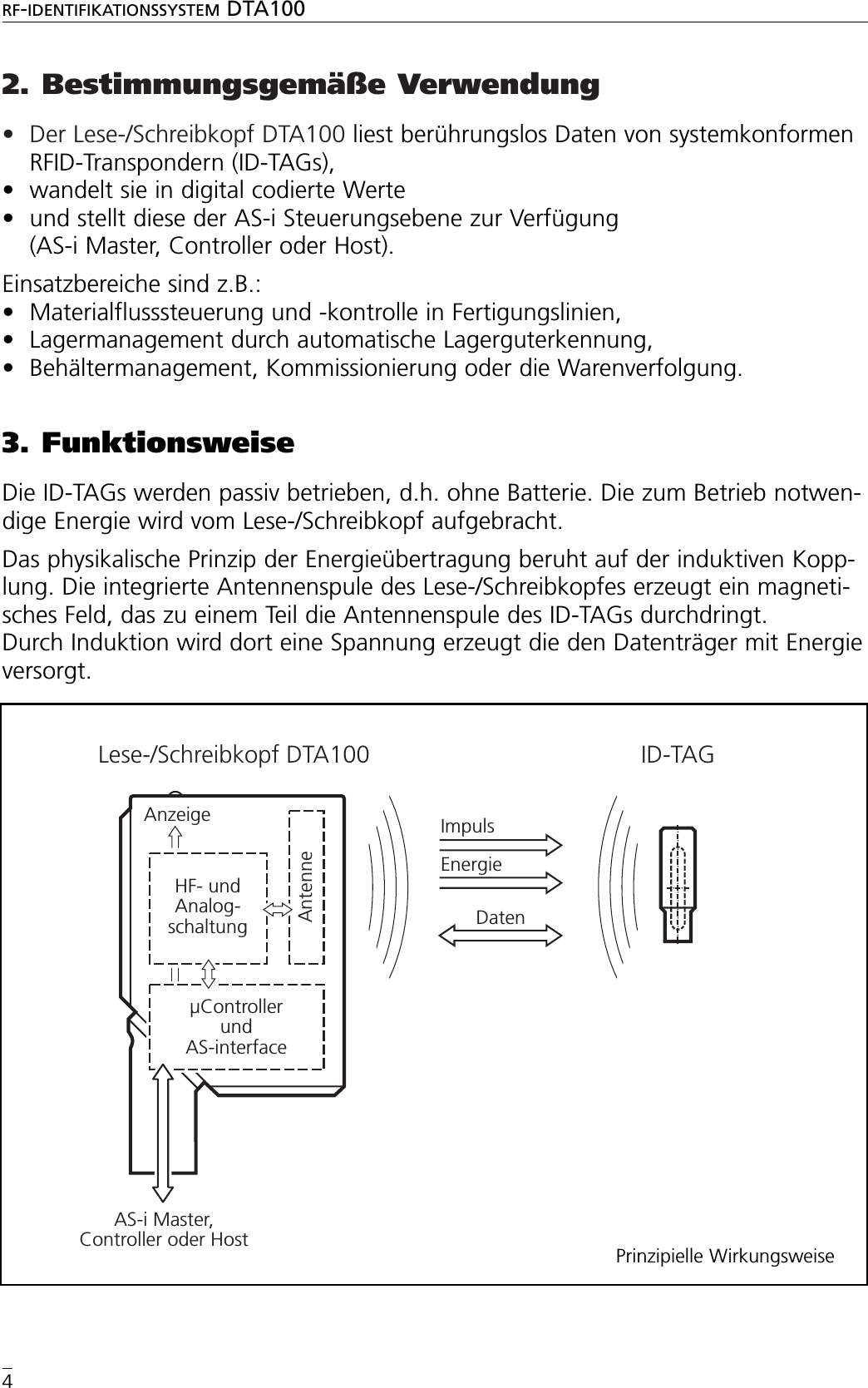
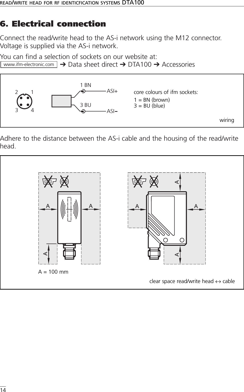
![7. Der Lese-/Schreibkopf im ASi-NetzwerkGrundeinstellungAdressierungDer Lese-/Schreibkopf wird adressiert mit einem Adressiergerät (z.B. AC1144), demMaster oder mit der AS-i-Software des Hosts (die Komponenten müssen AS-i Versi-on 2.1 unterstützen).Vergeben Sie eine Adresse zwischen 1 und 31.Analogwert-RepräsentationFür das AS-Interface ist der Lese-/Schreibkopf ein Analogeingang-Slave mit Über-tragungsprotokoll nach Profil 7.4. Arbeitet der Master gemäß Master-Profil M3oder M4, erkennt er den Lese-/Schreibkopf automatisch und unterstützt das Profil7.4.Im Bereich der Analogwertübertragung sind die Profile 7.3 und 7.4 identisch.Das Handbuch mit der ausführlichen Beschreibung der AS-i Dienste nach Profil 7.4finden Sie im Internet unter:➔Datenblatt-Suche ➔DTA100 ➔weitere InformationenBelegung der DatenbitsIn einem Übertragungszyklus werden folgende Daten in Datentripel übertragen:Additional Information Bits:O = Overflow-Bit (wird bei den Werten 7FFF und 8000 Hex. gesetzt, sonst 0)V = Valid-Bit (wird bei einem gültigen Wert gesetzt)www.ifm-electronic.comRF-IDENTIFIKATIONSSYSTEM DTA1007DEUTSCHParameter WertI/O Code [hex] 7ID Code [hex] 4Extended ID2 Code [hex] CID1 Code für Codewert [hex] FSlave-Adresse (Werkseinstellung) 0E3 E2 E1D16D15D14D13D12D11D10D9D8D7D6D5D4D3D2D1 O VExtentionBits(statisch 0) User Data Bits](https://usermanual.wiki/ifm-electronic/DTS125-AA.User-Manual-DTA100/User-Guide-745727-Page-7.png)
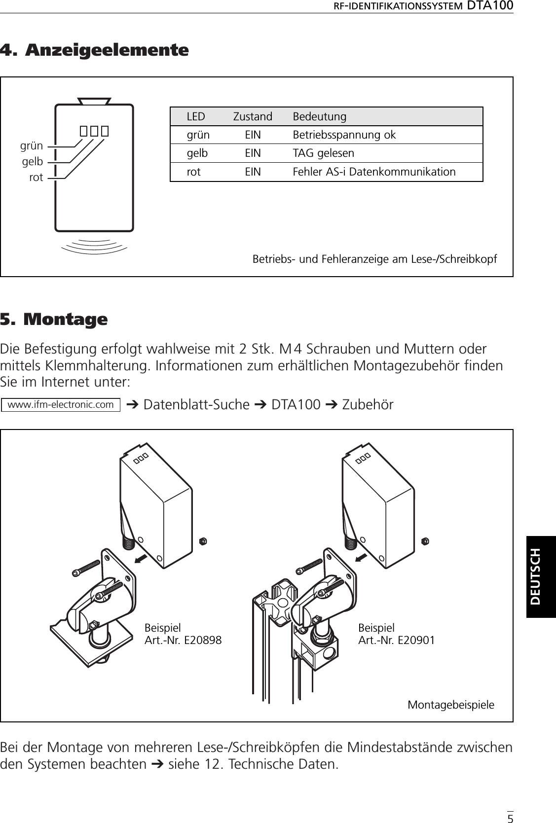
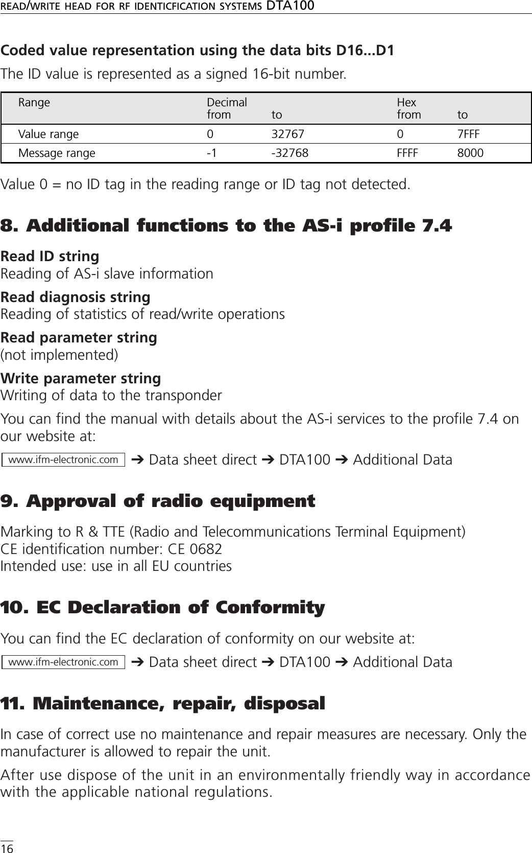
![12. Technische DatenRF-IDENTIFIKATIONSSYSTEM DTA1009DEUTSCHDTA100 Lese-/Schreibkopf DTS/125/RW/AS/US mit integriertem AS-i SlaveProfil 7.4schwenkbare M12-Steckverbindung1: integrierte Antenne, 2: TAG-Positioniermarke (Antennenmitte) Einsatzbereich Erkennen von Objekten auf Transporteinrichtungen;geeignet für Vorbeifahrgeschwindigkeiten bis 0,5 m/sElektrische Ausführung AS-iBetriebsspannung [V] 26,5...31,6 DC (AS-i)Stromaufnahme [mA] 50Arbeitsfrequenz [kHz] 125Vorbeifahrgeschwindigkeit * [m/s] Lesen: 0,5Schreiben: nur statischAbstand zum ID-TAG * [mm] Lesen: 15 (bei 0,5 m/s); 20 (statisch)Schreiben: 10 (statisch)Abstand Lese-/Schreibkopf [mm] Lesen: 200Lesen und Schreiben: 400Datenbereitstellungszeit [ms] 70Wertebereich 16 Bit (15 Bit ID-Wert, 1 Bit Meldungen)Umgebungsbedingungen Umgebungstemperatur: -20...50 °CLagertemperatur: -25....80 °CVibration: 20 g; 10...2000 HzSchock: 50 g; 11 msSchutzart, Schutzklasse IP 67, IIIAS-i-Profil 7.4E/A-Konfiguration [Hex] 7ID-Code [Hex] 4AS-i-Zertifikat 71501EMV EN 50295 (1999-03)Gehäusewerkstoffe PA (Polyamid)Anzeige 3 LEDgrün: Betriebsspannunggelb: TAG gelesenrot: Fehler AS-i DatenkommunikationAnschluss M12-Steckverbindung Bemerkungen *) bezogen auf ID-TAG E80301 (Mitte Schraube)Abstände zu anderen ID-TAGs siehe jeweiliges Datenblatt (E803xx)ifm electronic gmbh • Teichstraße 4 • D-45127 Essen Technische bnderungen behalten wir uns ohne Ankündigung vor ! DE - DTA100 17.03.2006](https://usermanual.wiki/ifm-electronic/DTS125-AA.User-Manual-DTA100/User-Guide-745727-Page-9.png)
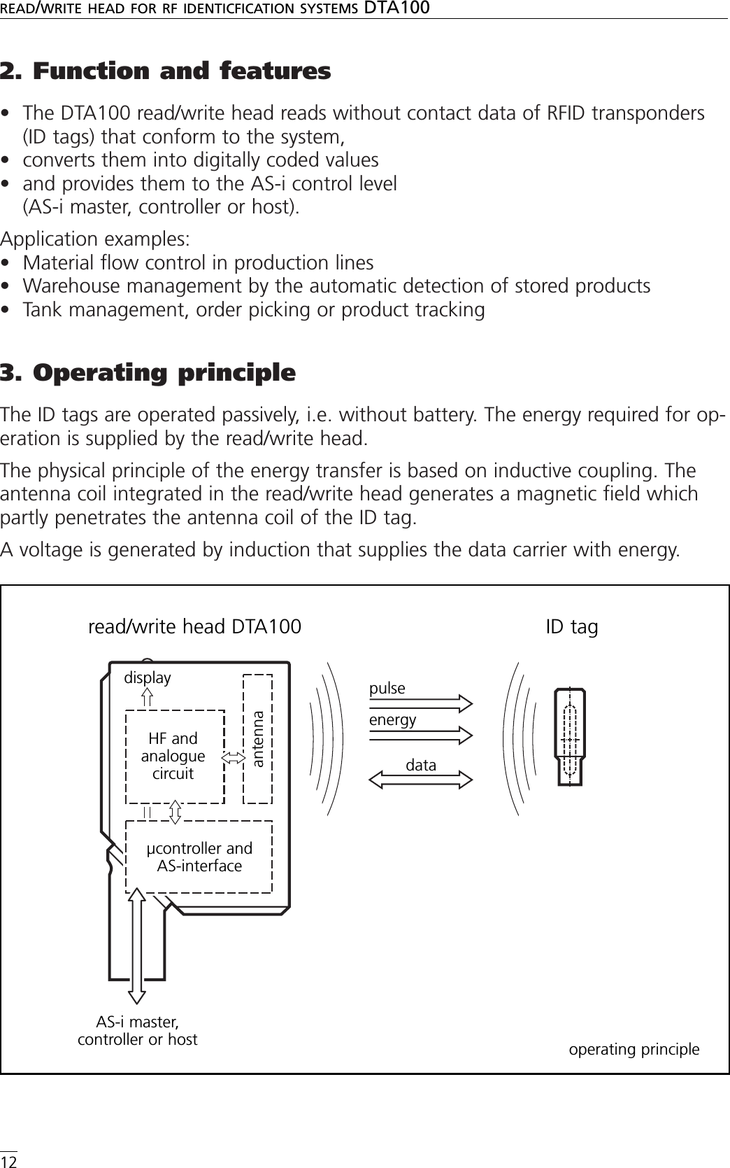
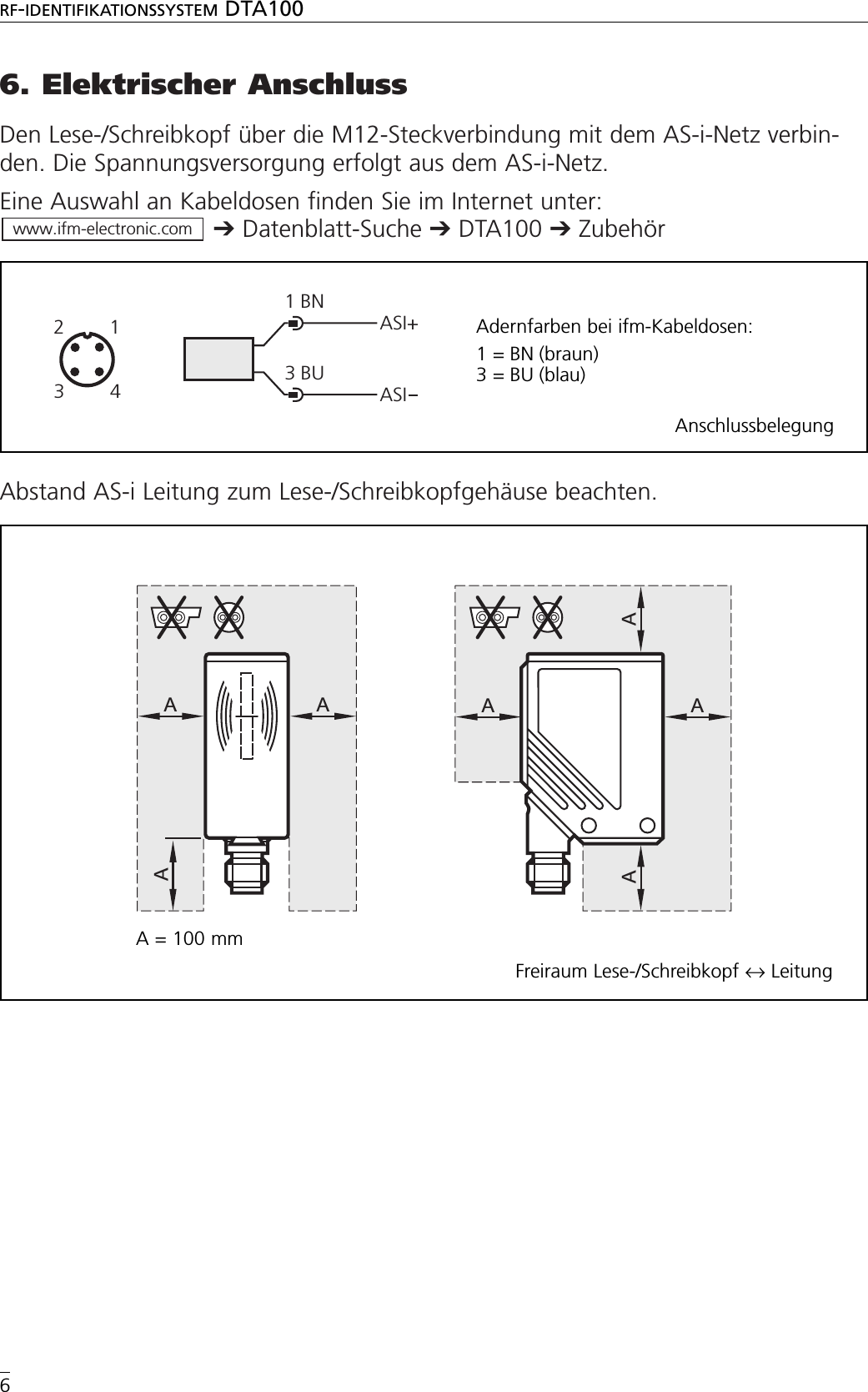
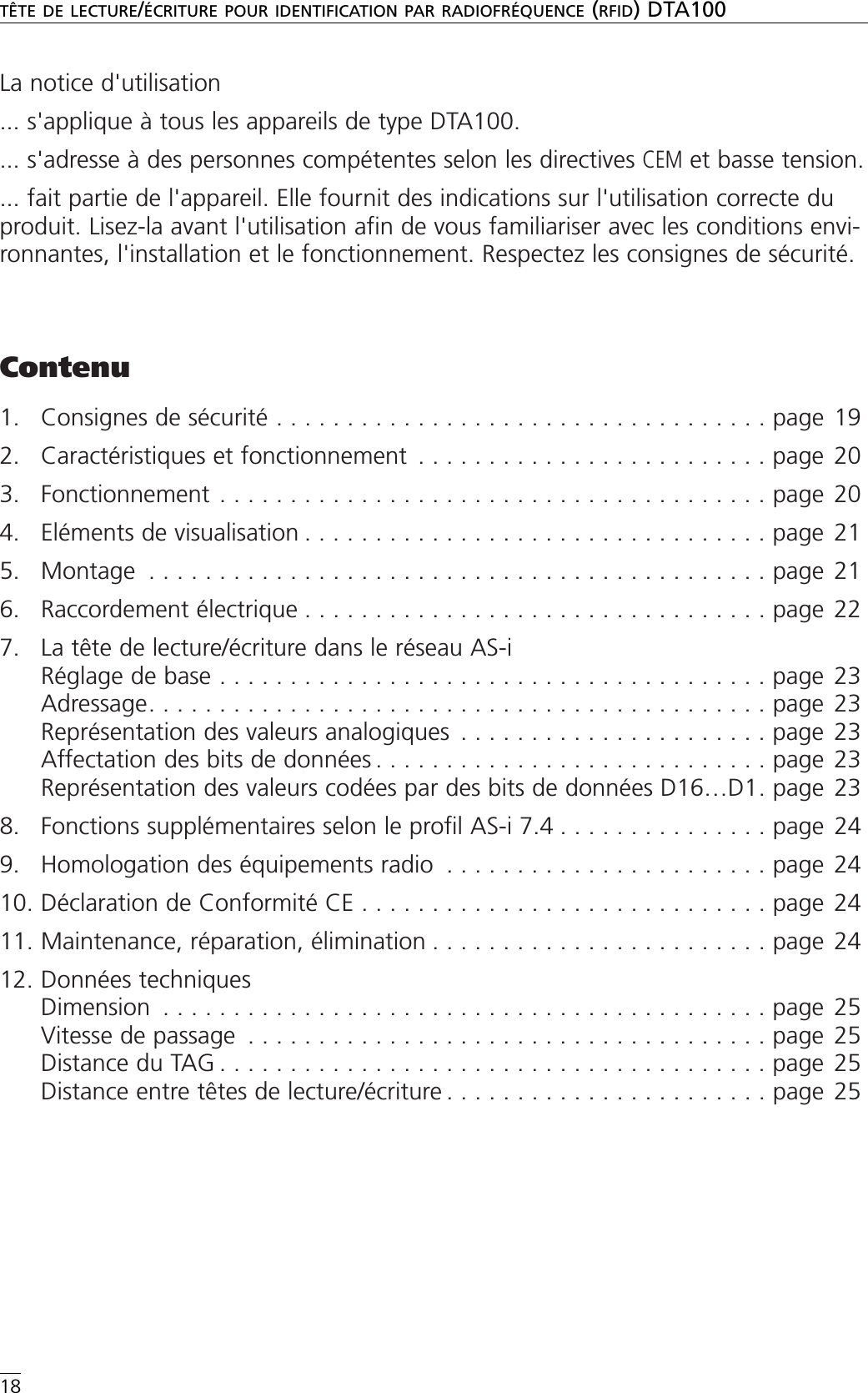
![7. The read/write head in the AS-i networkBasic settingAddressingThe read/write head is addressed using an addressing unit (e.g. AC1144), the mas-ter or the AS-i software of the host (the components must support the AS-i version2.1).Assign an address between 1 and 31.Analogue value representationFor the AS-interface the read/write head is a slave having an analogue input withthe transmission protocol to the profile 7.4. If the master operates to the masterprofile M3 or M4, it automatically detects the read/write head and supports theprofile 7.4.For the analogue value transmission the profiles 7.3 and 7.4 are identical.You can find the manual with details about the AS-i services to the profile 7.4 onour website at:➔Data sheet direct ➔DTA100 ➔Additional DataAssignment of the data bitsIn one transmission cycle the following data are transferred in data triples.Additional information bits:O = overflow bit (is set for the values 7FFF and 8000 hex, otherwise 0)V = valid bit (is set for a valid value)www.ifm-electronic.comREAD/WRITE HEAD FOR RF IDENTICFICATION SYSTEMS DTA10015ENGLISHParameters ValuesI/O code [hex] 7ID code [hex] 4Extended ID2 code [hex] CID1 code for coded value [hex] FSlave address (factory setting) 0E3 E2 E1D16D15D14D13D12D11D10D9D8D7D6D5D4D3D2D1 O VExtentionBits(statisch 0) User Data Bitsuser data bitsextensionbits(static 0)](https://usermanual.wiki/ifm-electronic/DTS125-AA.User-Manual-DTA100/User-Guide-745727-Page-15.png)
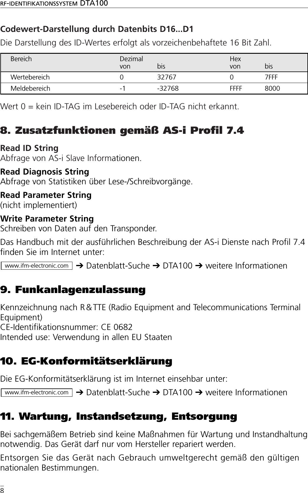
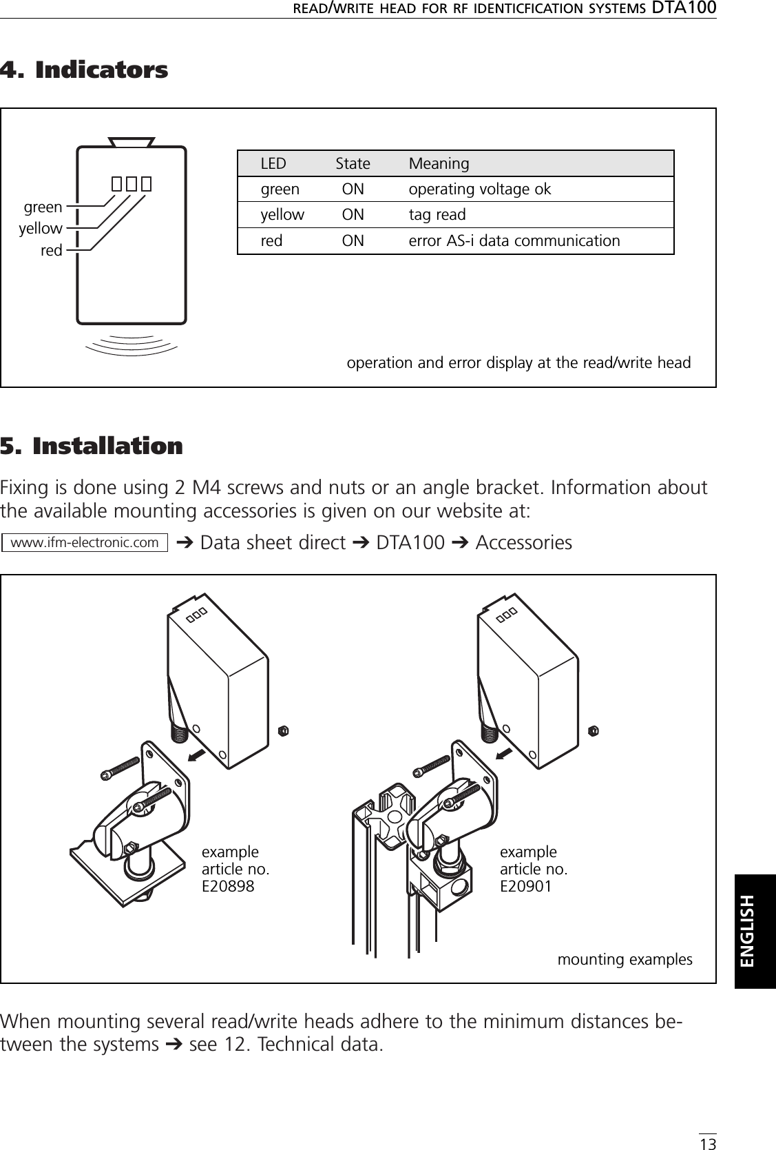
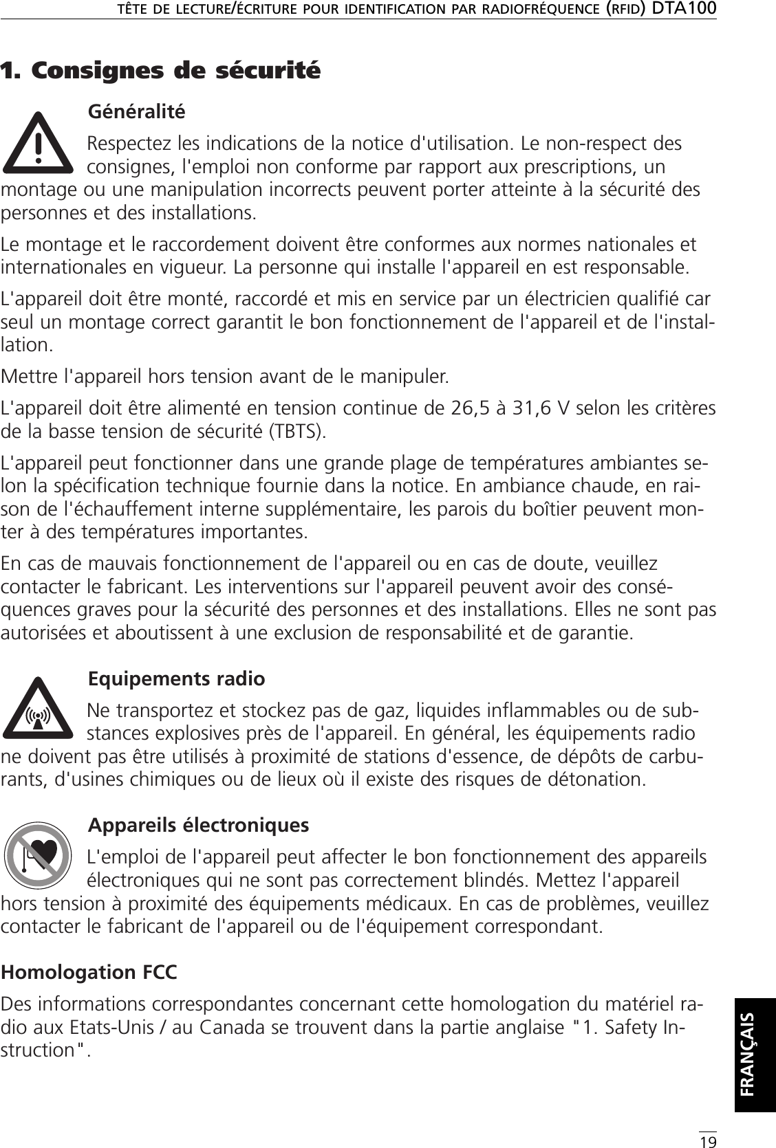
![12. Technical dataREAD/WRITE HEAD FOR RF IDENTICFICATION SYSTEMS DTA10017ENGLISHDTA100 Read/write head DTS/125/RW/AS/US with integrated AS-i slave profile 7.4rotatable M12 connector1: integrated antenna , 2: tag positioning mark (middle of the antenna) Application Detection of objects on conveying systems;suitable for travel speeds up to 0.5 m/sElectrical design AS-iOperating voltage [V] 26.5...31.6 DC (AS-i)Current consumption [mA] 50Operating frequency [kHz] 125Travel speed * [m/s] read: 0.5write: only static Distance to the ID tag * [mm] read: 15 (at 0.5 m/s); 20 (static)write: 10 (static)Separation between read/write heads [mm]read: 200read and write: 400Data provision time [ms] 70Value range 16 bits (15-bit ID value, 1-bit message)Operating conditions operating temperature: -20...50 °Cstorage temperature: -25....80 °Cvibration: 20 g; 10...2000 Hzshock: 50 g; 11 msProtection IP 67, IIIAS-i profile 7.4I/O configuration [Hex] 7ID code [Hex] 4AS-i certificate 71501EMC EN 50295 (1999-03)Housing material PA (polyamide)Display 3 LEDgreen: operating voltage yellow: tag readred: error AS-i data communicationConnection M12 connector Remarks *) referred to the ID tag E80301 (middle of the screw)For the distances to other ID tags see the respective data sheet (E803xx)ifm electronic gmbh • Teichstraße 4 • D-45127 Essen We reserve the right to make technical alterations without prior notice . GB - DTA100 17.03.2006](https://usermanual.wiki/ifm-electronic/DTS125-AA.User-Manual-DTA100/User-Guide-745727-Page-17.png)
![7. La tête de lecture/écriture dans le réseau AS-iRéglages de baseAdressageLa tête de lecture/écriture est adressée à l'aide d'une unité d'adressage (par ex.AC1144), le maître AS-i ou le logiciel AS-i du système de commande (les compo-sants doivent être compatibles avec la version AS-i V 2.1).Affectez une adresse entre 1 et 31.Représentation des valeurs analogiquesLa tête de lecture / écriture est considérée comme un esclave AS-i à une entréeanalogique utilisant le protocole de transmission suivant le profil AS-i 7.4. Si lemaître AS-i travaille selon le profil maître M3 ou M4, il détecte automatiquementla tête de lecture/écriture et est compatible avec le profil 7.4.Pour la transmission de valeurs analogiques les profils 7.3 et 7.4 sont identiques.Vous trouvez le manuel donnant un descriptif détaillé de la communication AS-iselon le profil 7.4 sur notre site web à :➔Fiche technique ➔DTA100 ➔Information sur le ProduitAffectation des bits de donnéesDans un cycle de transmission les données suivantes sont transmises par triplets dedonnées :Bits d'information supplémentaires :O = bit de débordement (est mis à 1 pour les valeurs 7FFF et 8000 hexa, sinon 0)V = bit valable (est mis à 1 pour une valeur valable)www.ifm-electronic.comTÊTE DE LECTURE/ÉCRITURE POUR IDENTIFICATION PAR RADIOFRÉQUENCE (RFID) DTA10023FRANÇAISProfil AS-i / Adresse ValeursCode E/S [hexa] 7Code ID [hexa] 4Code ID2 [hexa] CCode ID1 [hexa] FAdresse d'esclave (réglage usine) 0E3 E2 E1D16D15D14D13D12D11D10D9D8D7D6D5D4D3D2D1 O VExtentionBits(statisch 0) User Data Bitsbits de données utilisateursbitsd'extension(0 statique)](https://usermanual.wiki/ifm-electronic/DTS125-AA.User-Manual-DTA100/User-Guide-745727-Page-23.png)
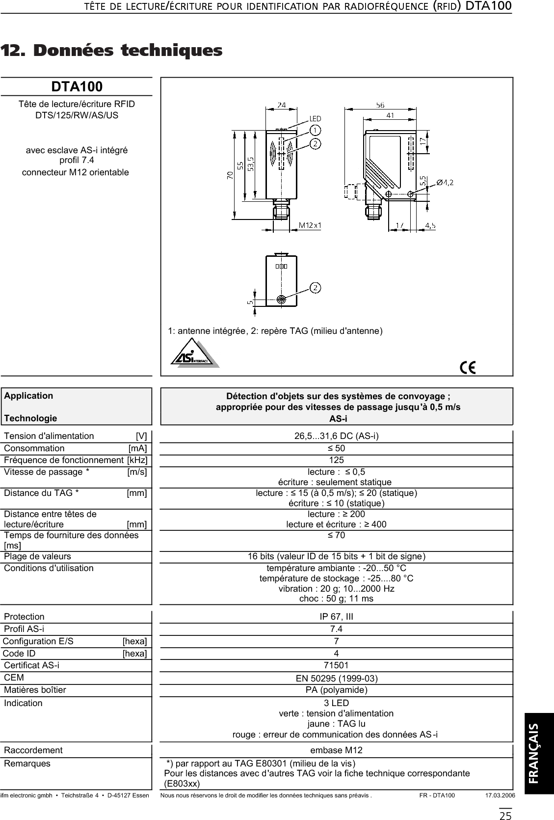
![12. Données techniquesTÊTE DE LECTURE/ÉCRITURE POUR IDENTIFICATION PAR RADIOFRÉQUENCE (RFID) DTA10025FRANÇAISDTA100 Tête de lecture/écriture RFID DTS/125/RW/AS/US avec esclave AS-i intégré profil 7.4connecteur M12 orientable 1: antenne intégrée, 2: repère TAG (milieu d'antenne) Application Détection d'objets sur des systèmes de convoyage ; appropriée pour des vitesses de passage jusqu'à 0,5 m/sTechnologie AS-iTension d'alimentation [V] 26,5...31,6 DC (AS-i)Consommation [mA] 50Fréquence de fonctionnement [kHz] 125Vitesse de passage * [m/s] lecture : 0,5écriture : seulement statique Distance du TAG * [mm] lecture : 15 (à 0,5 m/s); 20 (statique)écriture : 10 (statique)Distance entre têtes de lecture/écriture [mm]lecture : 200lecture et écriture : 400Temps de fourniture des données [ms] 70Plage de valeurs 16 bits (valeur ID de 15 bits + 1 bit de signe)Conditions d'utilisation température ambiante : -20...50 °Ctempérature de stockage : -25....80 °Cvibration : 20 g; 10...2000 Hzchoc : 50 g; 11 msProtection IP 67, IIIProfil AS-i 7.4Configuration E/S [hexa] 7Code ID [hexa] 4Certificat AS-i 71501CEM EN 50295 (1999-03)Matières boîtier PA (polyamide)Indication 3 LEDverte : tension d'alimentation jaune : TAG lu rouge : erreur de communication des données AS -i Raccordement embase M12 Remarques *) par rapport au TAG E80301 (milieu de la vis)Pour les distances avec d'autres TAG voir la fiche technique correspondante (E803xx)ifm electronic gmbh • Teichstraße 4 • D-45127 Essen Nous nous réservons le droit de modifier les données techniques sans préavis . FR - DTA100 17.03.2006](https://usermanual.wiki/ifm-electronic/DTS125-AA.User-Manual-DTA100/User-Guide-745727-Page-25.png)