ifm electronic DTS125-AA RFID Reader User Manual DTA100
ifm electronic gmbh RFID Reader DTA100
Contents
- 1. User Manual DTA100
- 2. User Manual DTA101
User Manual DTA100
Betriebsanleitung
Operating instructions
Notice d'utilisation
Lese-/Schreibkopf für
RF-Identifikationssysteme
Read/write head for
RF identification systems
Tête de lecture/écriture
pour identification par
radiofréquence (RFID)
DTA100
DEUTSCHENGLISH
FRANÇAIS
Sachnr. 701911 /01 10/2006

Diese Betriebsanleitung
... gilt für alle Geräte des Typs DTA100.
... richtet sich an fachkundige Personen im Sinne von EMV- und der Niederspan-
nungs-Richtlinie.
... ist Bestandteil des Gerätes. Sie enthält Angaben zum korrekten Umgang mit
dem Produkt. Lesen Sie sie vor dem Einsatz, damit Sie mit Einsatzbedingungen, In-
stallation und Betrieb vertraut werden. Befolgen Sie die Sicherheitshinweise.
Inhalt
1. Sicherheitsweise . . . . . . . . . . . . . . . . . . . . . . . . . . . . . . . . . . . . . . . . Seite 3
2. Bestimmungsgemäße Verwendung . . . . . . . . . . . . . . . . . . . . . . . . . . Seite 4
3. Funktionsweise . . . . . . . . . . . . . . . . . . . . . . . . . . . . . . . . . . . . . . . . . Seite 4
4. Anzeigeelemente . . . . . . . . . . . . . . . . . . . . . . . . . . . . . . . . . . . . . . . Seite 5
5. Montage . . . . . . . . . . . . . . . . . . . . . . . . . . . . . . . . . . . . . . . . . . . . . Seite 5
6. Elektrischer Anschluss . . . . . . . . . . . . . . . . . . . . . . . . . . . . . . . . . . . . Seite 6
7. Der Lese-/Schreibkopf im AS-i Netzwerk
Grundeinstellung . . . . . . . . . . . . . . . . . . . . . . . . . . . . . . . . . . . . . . . Seite 7
Adressierung . . . . . . . . . . . . . . . . . . . . . . . . . . . . . . . . . . . . . . . . . . Seite 7
Analogwert-Repräsentation . . . . . . . . . . . . . . . . . . . . . . . . . . . . . . . . Seite 7
Belegung der Datenbits . . . . . . . . . . . . . . . . . . . . . . . . . . . . . . . . . . . Seite 7
Codewert-Darstellung durch Datenbit D16...D1 . . . . . . . . . . . . . . . . . Seite 7
8. Zusatzfunktionen gemäß AS-i Profil 7.4 . . . . . . . . . . . . . . . . . . . . . . . Seite 8
9. Funkanlagenzulassung. . . . . . . . . . . . . . . . . . . . . . . . . . . . . . . . . . . . Seite 8
10. EG-Konformitätserklärung . . . . . . . . . . . . . . . . . . . . . . . . . . . . . . . . . Seite 8
11. Wartung, Instandsetzung, Entsorgung . . . . . . . . . . . . . . . . . . . . . . . . Seite 8
12. Technische Daten
Maße . . . . . . . . . . . . . . . . . . . . . . . . . . . . . . . . . . . . . . . . . . . . . . . . Seite 9
Vorbeifahrgeschwindigkeit. . . . . . . . . . . . . . . . . . . . . . . . . . . . . . . . . Seite 9
Abstand zum ID-TAG . . . . . . . . . . . . . . . . . . . . . . . . . . . . . . . . . . . . Seite 9
Abstand Lese-/Schreibköpfe. . . . . . . . . . . . . . . . . . . . . . . . . . . . . . . . Seite 9
RF-IDENTIFIKATIONSSYSTEM DTA100
2
1. Sicherheitshinweise
Allgemeines
Befolgen Sie die Angaben der Betriebsanleitung. Nichtbeachten der Hin-
weise, Verwendung außerhalb der nachstehend genannten bestim-
mungsgemäßen Verwendung, falsche Installation oder Handhabung können Beein-
trächtigungen der Sicherheit von Menschen und Anlagen zur Folge haben.
Der Einbau und Anschluss muss den gültigen nationalen und internationalen Nor-
men entsprechen. Die Verantwortung trägt derjenige, der das Gerät installiert.
Das Gerät darf nur von einer Elektrofachkraft eingebaut, angeschlossen und in Be-
trieb gesetzt werden, da die sichere Funktion des Gerätes und der Anlage nur bei
ordnungsgemäßer Installation gewährleistet ist.
Schalten Sie das Gerät extern spannungsfrei bevor Sie irgendwelche Arbeiten an
ihm vornehmen.
Das Gerät muss gemäß den Kriterien für sichere Kleinspannung (SELV) mit einer
externen Gleichspannung von 26,5...31,6 V versorgt werden.
Das Gerät ist gemäß nachstehender technischer Spezifikation in einem weiten Um-
gebungstemperaturbereich betreibbar. Aufgrund der zusätzlichen Eigenerwärmung
kann es an den Gehäusewandungen beim Berühren in heißer Umgebung zu ho-
hen wahrnehmbaren Temperaturen kommen.
Bei Fehlfunktion des Gerätes oder bei Unklarheiten setzen Sie sich bitte mit dem
Hersteller in Verbindung. Eingriffe in das Gerät können schwerwiegende Beein-
trächtigungen der Sicherheit von Menschen und Anlagen zur Folge haben. Sie sind
nicht zulässig und führen zu Haftungs- und Gewährleistungsauschluss.
Funkanlagen
Transportieren und lagern Sie keine entflammbaren Gase, Flüssigkeiten
oder explosive Stoffe im Bereich des Gerätes. Funkgeräte dürfen generell
nicht in der Nähe von Tankstellen, Kraftstoffdepots, Chemiewerken oder Sprengar-
beiten benutzt werden.
Elektronische Geräte
Der Betrieb kann die Funktionsfähigkeit von nicht ordnungsgemäß ge-
schirmten elektronischen Geräten beeinträchtigen. Schalten Sie das
Gerät in der Nähe medizinischer Geräte aus. Bitte informieren Sie sich bei Störun-
gen ggf. beim Hersteller des jeweiligen Gerätes.
FCC Zulassungshinweis
Entsprechende Hinweise für die Funkzulassung USA/Kanada befinden sich im eng-
lischsprachigen Teil unter "1. Safety Instruction".
RF-IDENTIFIKATIONSSYSTEM DTA100
3
DEUTSCH
2. Bestimmungsgemäße Verwendung
• Der Lese-/Schreibkopf DTA100 liest berührungslos Daten von systemkonformen
RFID-Transpondern (ID-TAGs),
• wandelt sie in digital codierte Werte
• und stellt diese der AS-i Steuerungsebene zur Verfügung
(AS-i Master, Controller oder Host).
Einsatzbereiche sind z.B.:
• Materialflusssteuerung und -kontrolle in Fertigungslinien,
• Lagermanagement durch automatische Lagerguterkennung,
• Behältermanagement, Kommissionierung oder die Warenverfolgung.
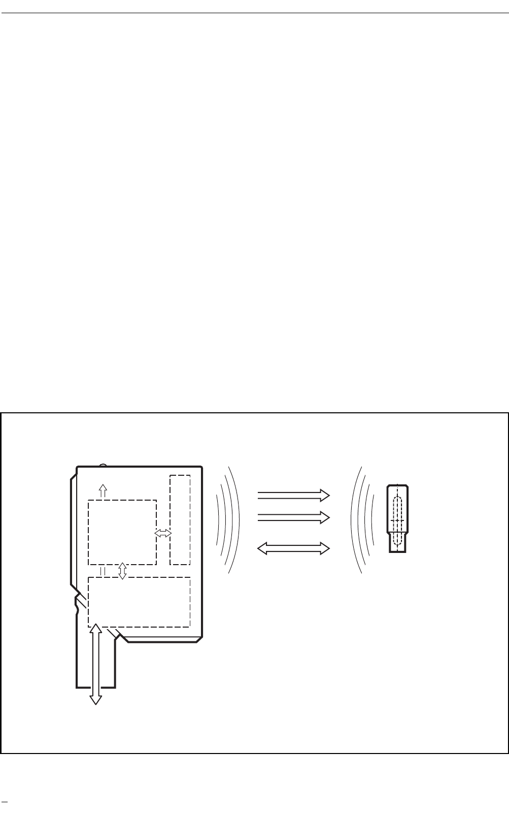
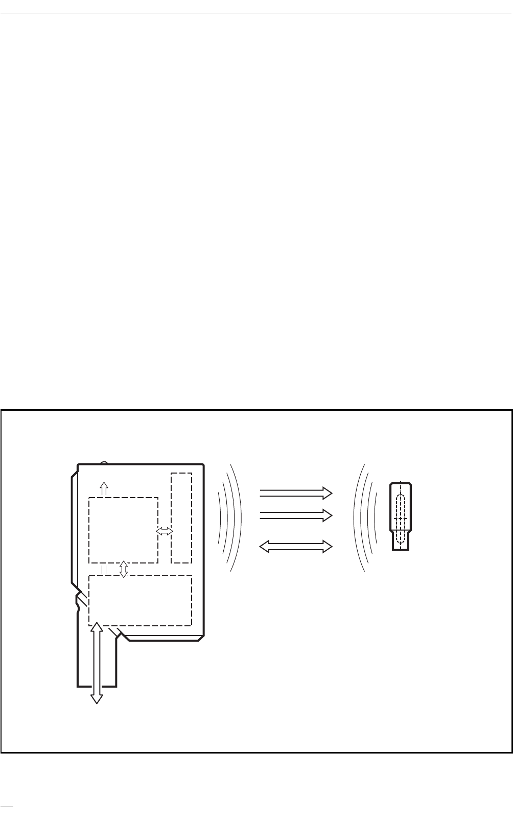
3. Funktionsweise
Die ID-TAGs werden passiv betrieben, d.h. ohne Batterie. Die zum Betrieb notwen-
dige Energie wird vom Lese-/Schreibkopf aufgebracht.
Das physikalische Prinzip der Energieübertragung beruht auf der induktiven Kopp-
lung. Die integrierte Antennenspule des Lese-/Schreibkopfes erzeugt ein magneti-
sches Feld, das zu einem Teil die Antennenspule des ID-TAGs durchdringt.
Durch Induktion wird dort eine Spannung erzeugt die den Datenträger mit Energie
versorgt.
RF-IDENTIFIKATIONSSYSTEM DTA100
4
AS-i Master,
Controller oder Host
Impuls
Lese-/Schreibkopf DTA100
Energie
HF- und
Analog-
schaltung
Antenne
Anzeige
µController
und
AS-interface
ID-TAG
Daten
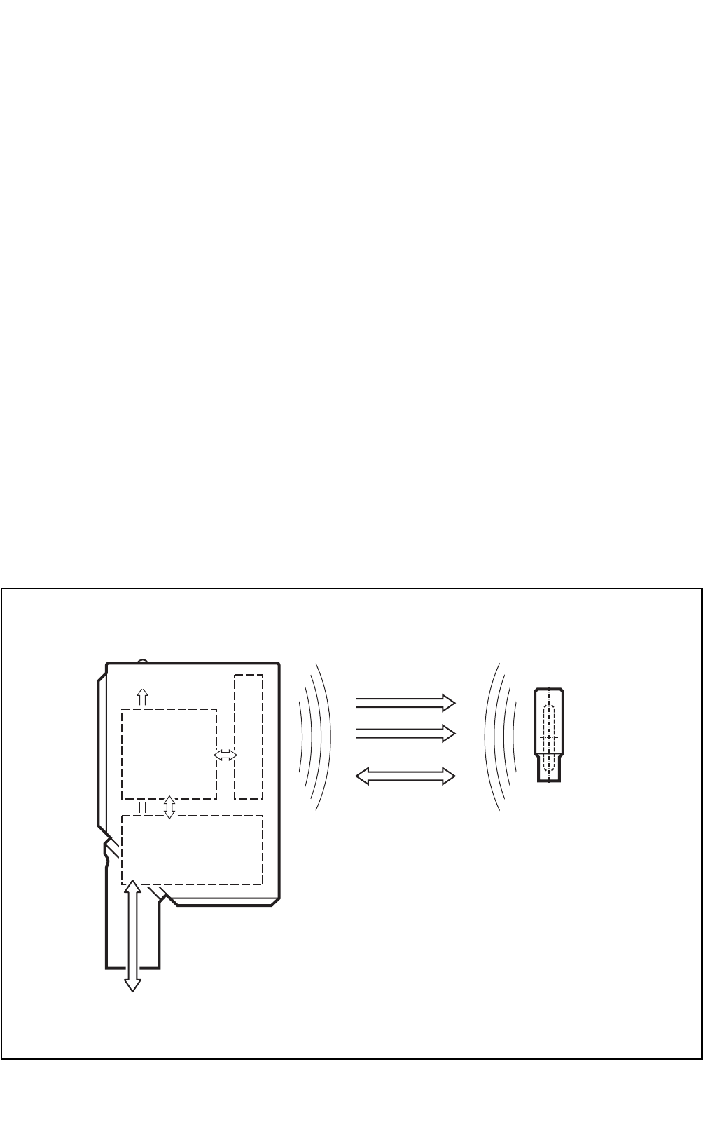
Prinzipielle Wirkungsweise
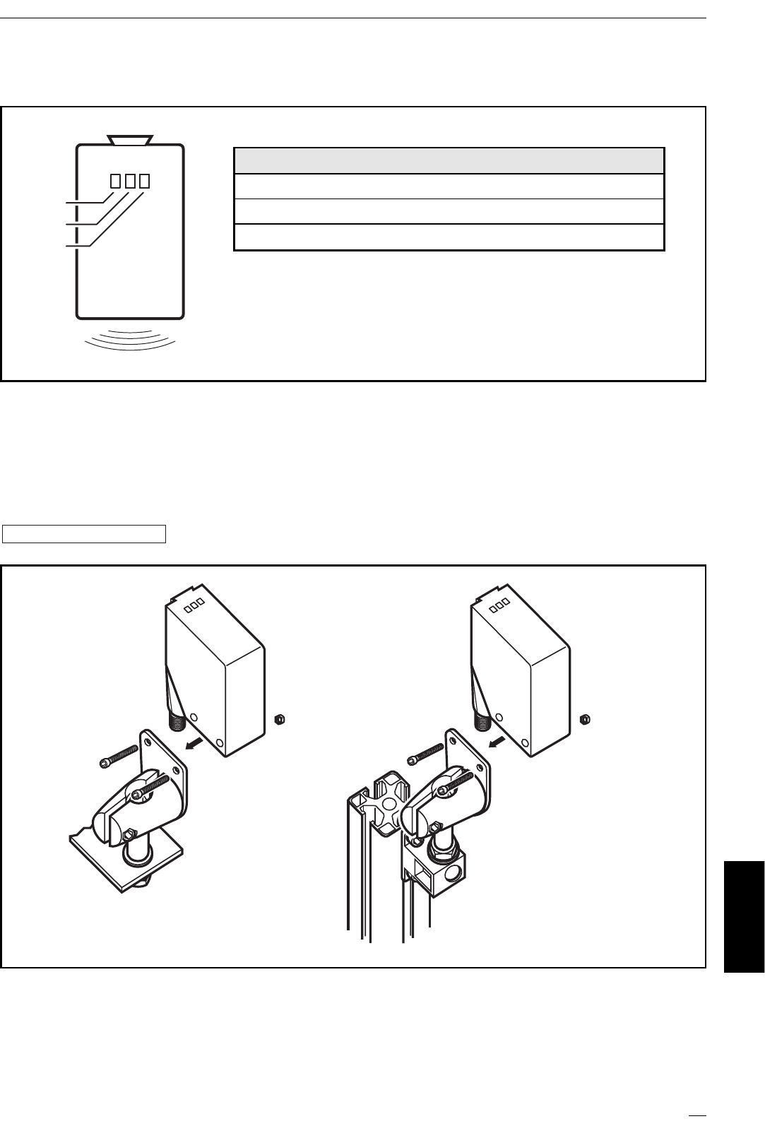
4. Anzeigeelemente
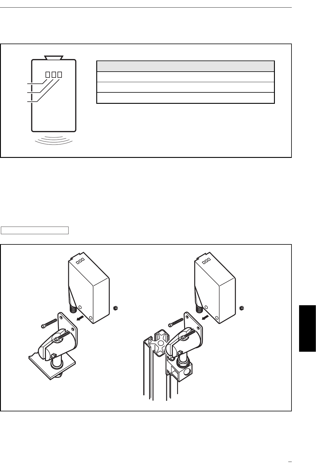
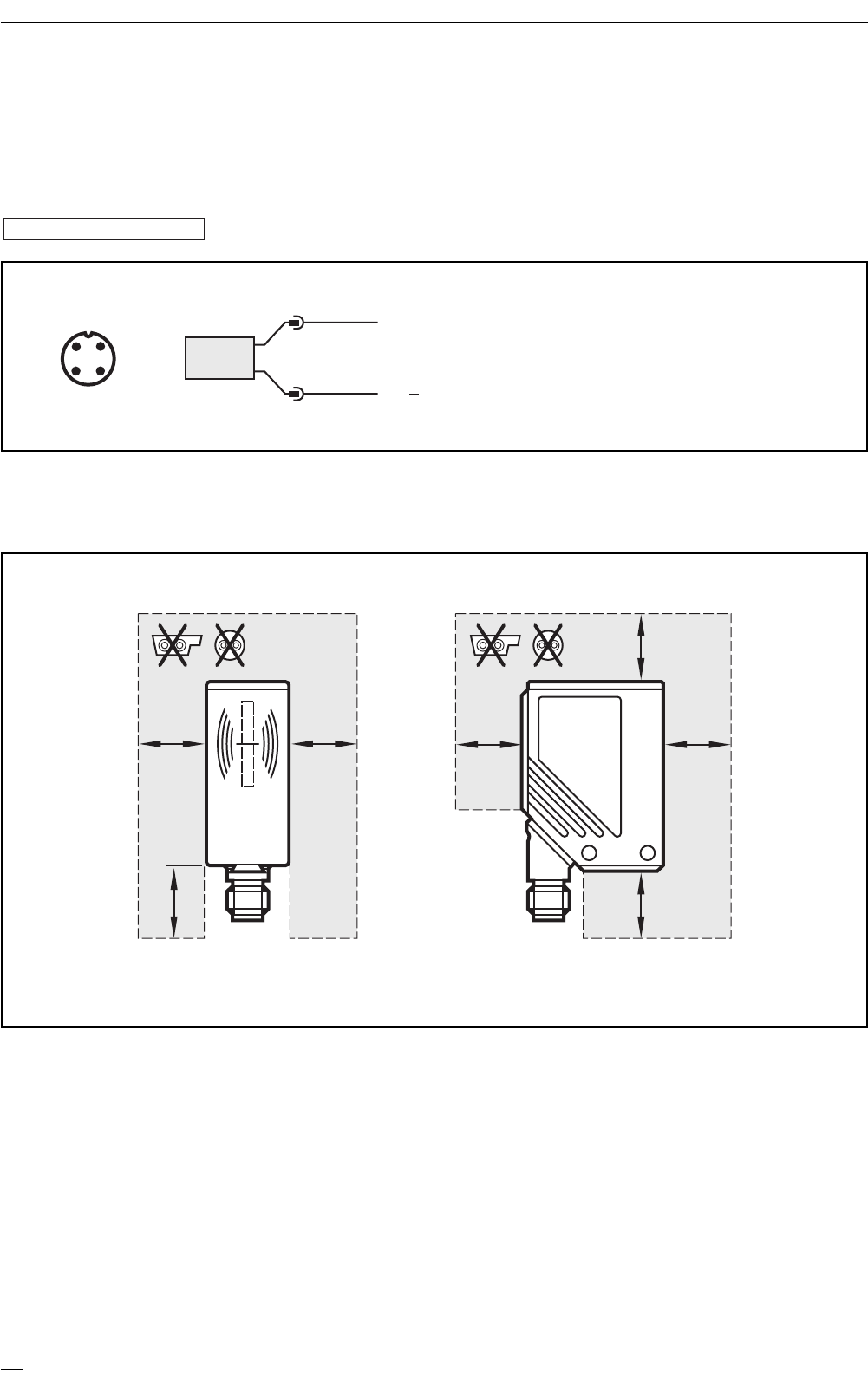
5. Montage
Die Befestigung erfolgt wahlweise mit 2 Stk. M4 Schrauben und Muttern oder
mittels Klemmhalterung. Informationen zum erhältlichen Montagezubehör finden
Sie im Internet unter:
➔Datenblatt-Suche ➔DTA100 ➔Zubehör
Bei der Montage von mehreren Lese-/Schreibköpfen die Mindestabstände zwischen
den Systemen beachten ➔siehe 12. Technische Daten.
www.ifm-electronic.com
RF-IDENTIFIKATIONSSYSTEM DTA100
5
DEUTSCH
rot
gelb
grün
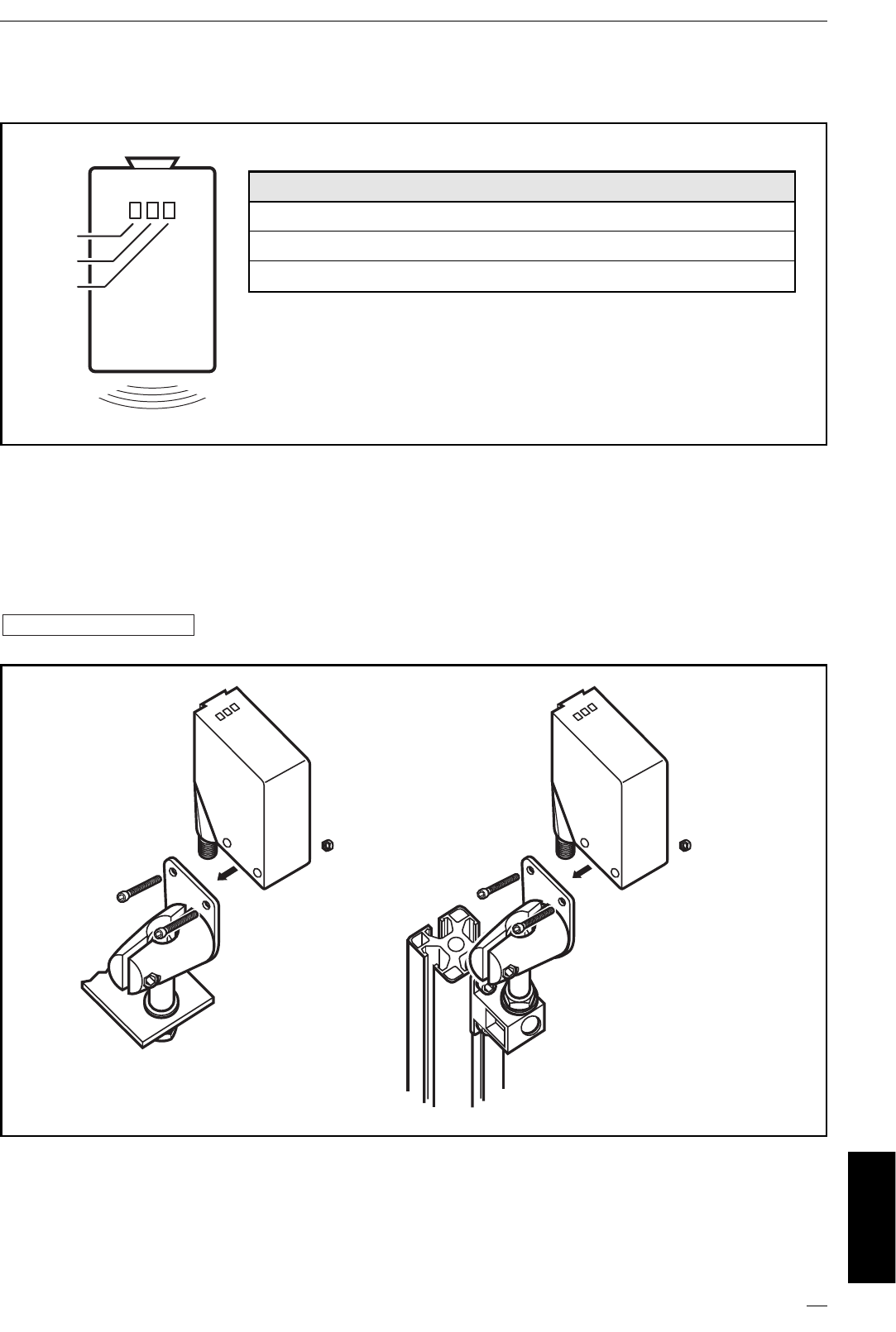
Betriebs- und Fehleranzeige am Lese-/Schreibkopf
LED Zustand Bedeutung
grün EIN Betriebsspannung ok
gelb EIN TAG gelesen
rot EIN Fehler AS-i Datenkommunikation
Montagebeispiele
Beispiel
Art.-Nr. E20901
Beispiel
Art.-Nr. E20898
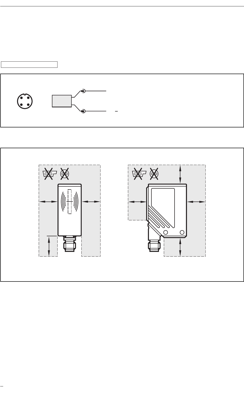
6. Elektrischer Anschluss
Den Lese-/Schreibkopf über die M12-Steckverbindung mit dem AS-i-Netz verbin-
den. Die Spannungsversorgung erfolgt aus dem AS-i-Netz.
Eine Auswahl an Kabeldosen finden Sie im Internet unter:
➔Datenblatt-Suche ➔DTA100 ➔Zubehör
Abstand AS-i Leitung zum Lese-/Schreibkopfgehäuse beachten.
www.ifm-electronic.com
RF-IDENTIFIKATIONSSYSTEM DTA100
6
ASI+
ASI
1
3
BN
BU
Adernfarben bei ifm-Kabeldosen:
1 = BN (braun)
3 = BU (blau)
Anschlussbelegung
4
21
3
AA AA
AA
A
Freiraum Lese-/Schreibkopf ↔Leitung
A = 100 mm
7. Der Lese-/Schreibkopf im ASi-Netzwerk
Grundeinstellung
Adressierung
Der Lese-/Schreibkopf wird adressiert mit einem Adressiergerät (z.B. AC1144), dem
Master oder mit der AS-i-Software des Hosts (die Komponenten müssen AS-i Versi-
on 2.1 unterstützen).
Vergeben Sie eine Adresse zwischen 1 und 31.
Analogwert-Repräsentation
Für das AS-Interface ist der Lese-/Schreibkopf ein Analogeingang-Slave mit Über-
tragungsprotokoll nach Profil 7.4. Arbeitet der Master gemäß Master-Profil M3
oder M4, erkennt er den Lese-/Schreibkopf automatisch und unterstützt das Profil
7.4.
Im Bereich der Analogwertübertragung sind die Profile 7.3 und 7.4 identisch.
Das Handbuch mit der ausführlichen Beschreibung der AS-i Dienste nach Profil 7.4
finden Sie im Internet unter:
➔Datenblatt-Suche ➔DTA100 ➔weitere Informationen
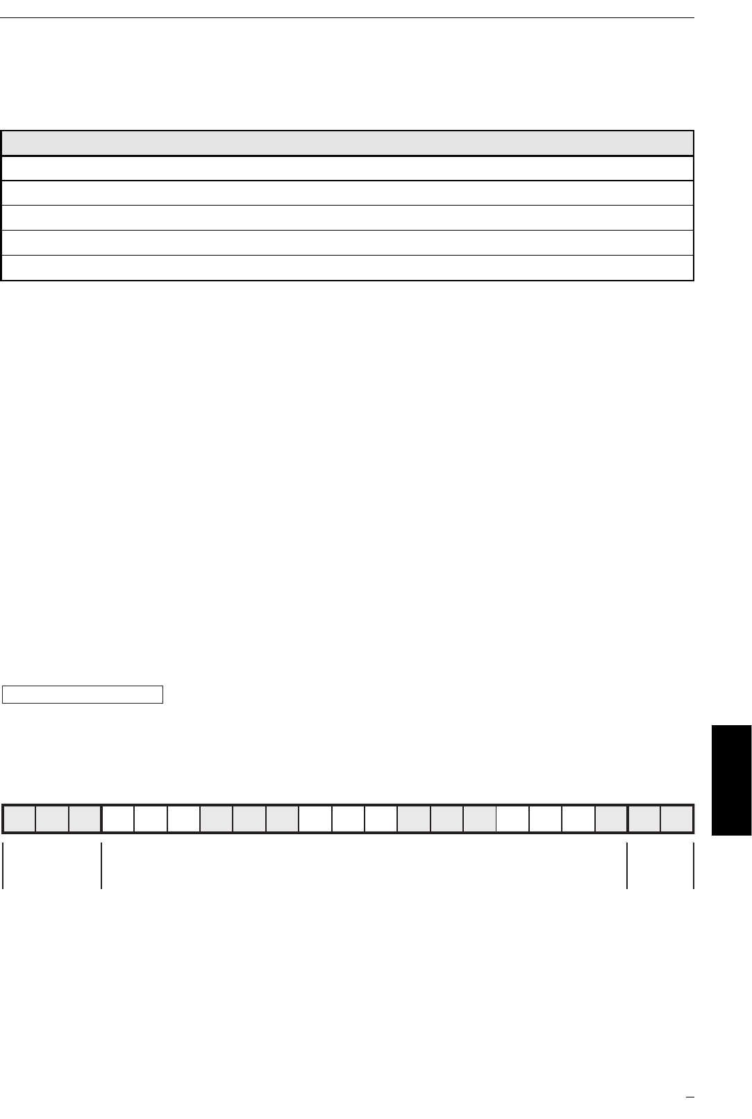
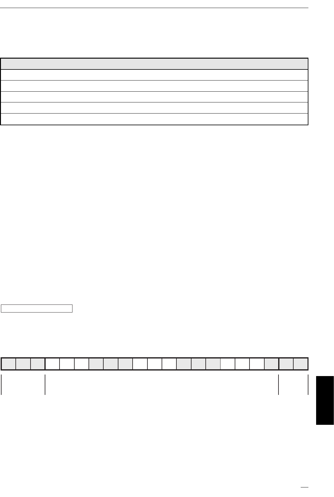
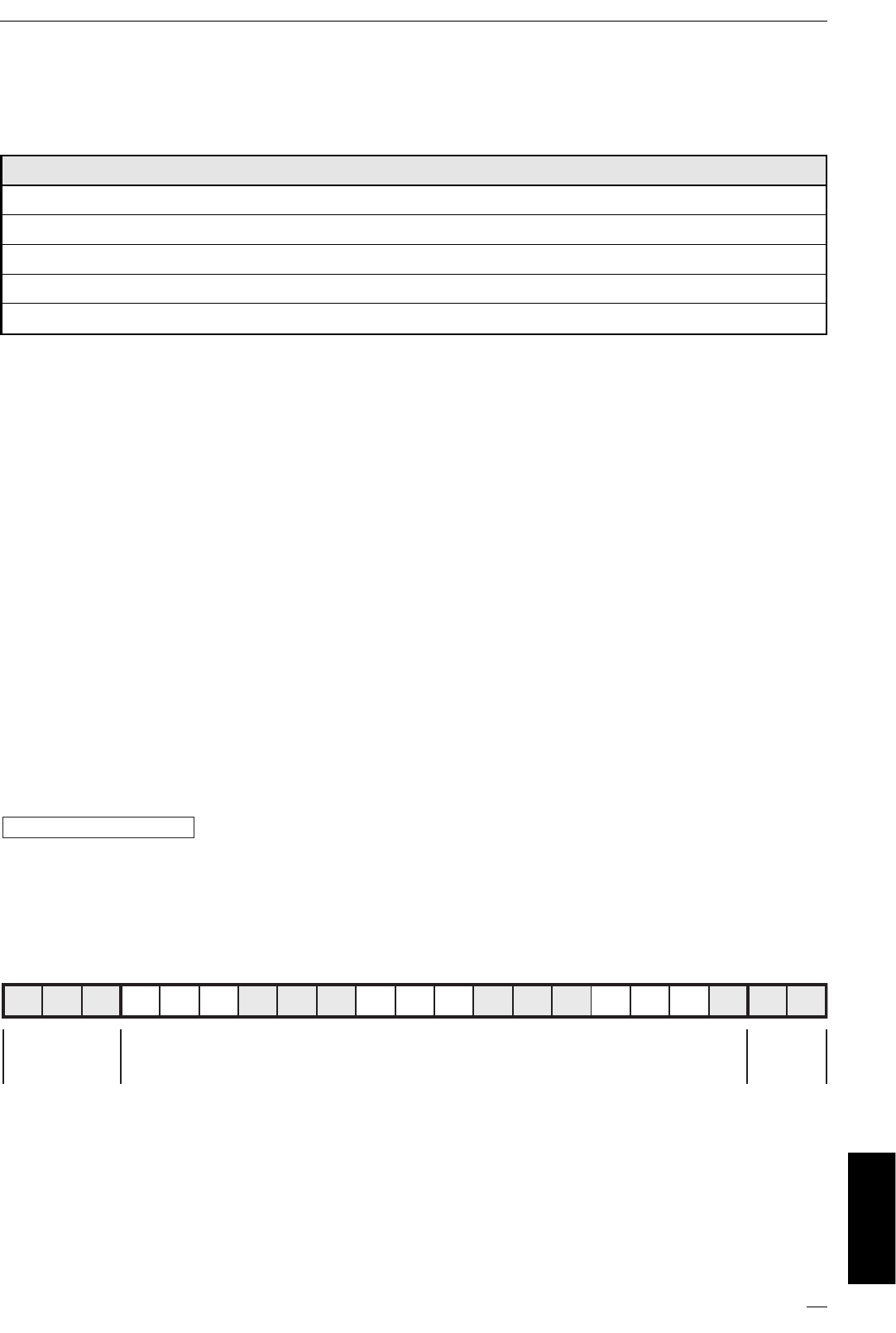
Belegung der Datenbits
In einem Übertragungszyklus werden folgende Daten in Datentripel übertragen:
Additional Information Bits:
O = Overflow-Bit (wird bei den Werten 7FFF und 8000 Hex. gesetzt, sonst 0)
V = Valid-Bit (wird bei einem gültigen Wert gesetzt)
www.ifm-electronic.com
RF-IDENTIFIKATIONSSYSTEM DTA100
7
DEUTSCH
Parameter Wert
I/O Code [hex] 7
ID Code [hex] 4
Extended ID2 Code [hex] C
ID1 Code für Codewert [hex] F
Slave-Adresse (Werkseinstellung) 0
E3 E2 E1D16D15D14D13D12D11D10D9D8D7D6D5D4D3D2D1 O V
Extention
Bits
(statisch 0) User Data Bits
Codewert-Darstellung durch Datenbits D16...D1
Die Darstellung des ID-Wertes erfolgt als vorzeichenbehaftete 16 Bit Zahl.
Wert 0 = kein ID-TAG im Lesebereich oder ID-TAG nicht erkannt.
8. Zusatzfunktionen gemäß AS-i Profil 7.4
Read ID String
Abfrage von AS-i Slave Informationen.
Read Diagnosis String
Abfrage von Statistiken über Lese-/Schreibvorgänge.
Read Parameter String
(nicht implementiert)
Write Parameter String
Schreiben von Daten auf den Transponder.
Das Handbuch mit der ausführlichen Beschreibung der AS-i Dienste nach Profil 7.4
finden Sie im Internet unter:
➔Datenblatt-Suche ➔DTA100 ➔weitere Informationen
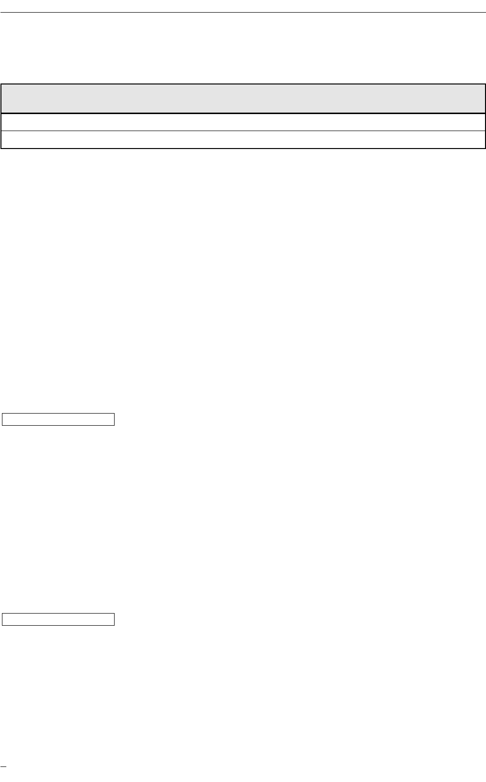
9. Funkanlagenzulassung
Kennzeichnung nach R&TTE (Radio Equipment and Telecommunications Terminal
Equipment)
CE-Identifikationsnummer: CE 0682
Intended use: Verwendung in allen EU Staaten
10. EG-Konformitätserklärung
Die EG-Konformitätserklärung ist im Internet einsehbar unter:
➔Datenblatt-Suche ➔DTA100 ➔weitere Informationen
11. Wartung, Instandsetzung, Entsorgung
Bei sachgemäßem Betrieb sind keine Maßnahmen für Wartung und Instandhaltung
notwendig. Das Gerät darf nur vom Hersteller repariert werden.
Entsorgen Sie das Gerät nach Gebrauch umweltgerecht gemäß den gültigen
nationalen Bestimmungen.
www.ifm-electronic.com
www.ifm-electronic.com
RF-IDENTIFIKATIONSSYSTEM DTA100
8
Bereich Dezimal Hex
von bis von bis
Wertebereich 0 32767 0 7FFF
Meldebereich -1 -32768 FFFF 8000
12. Technische Daten
RF-IDENTIFIKATIONSSYSTEM DTA100
9
DEUTSCH
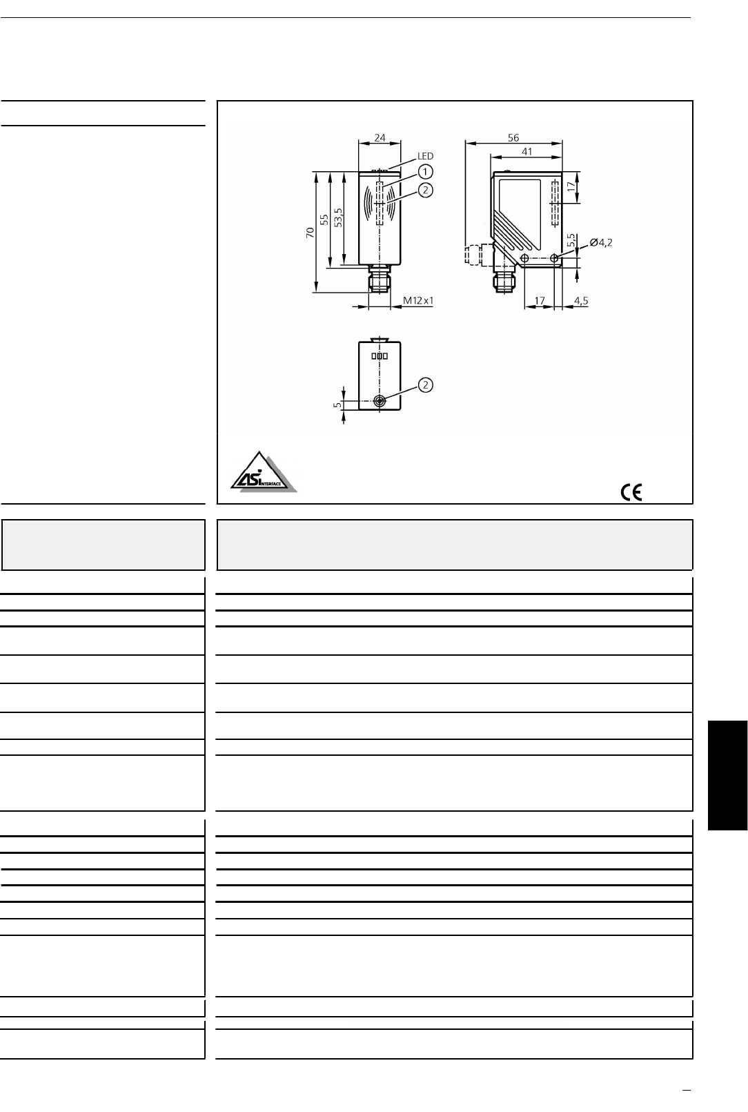
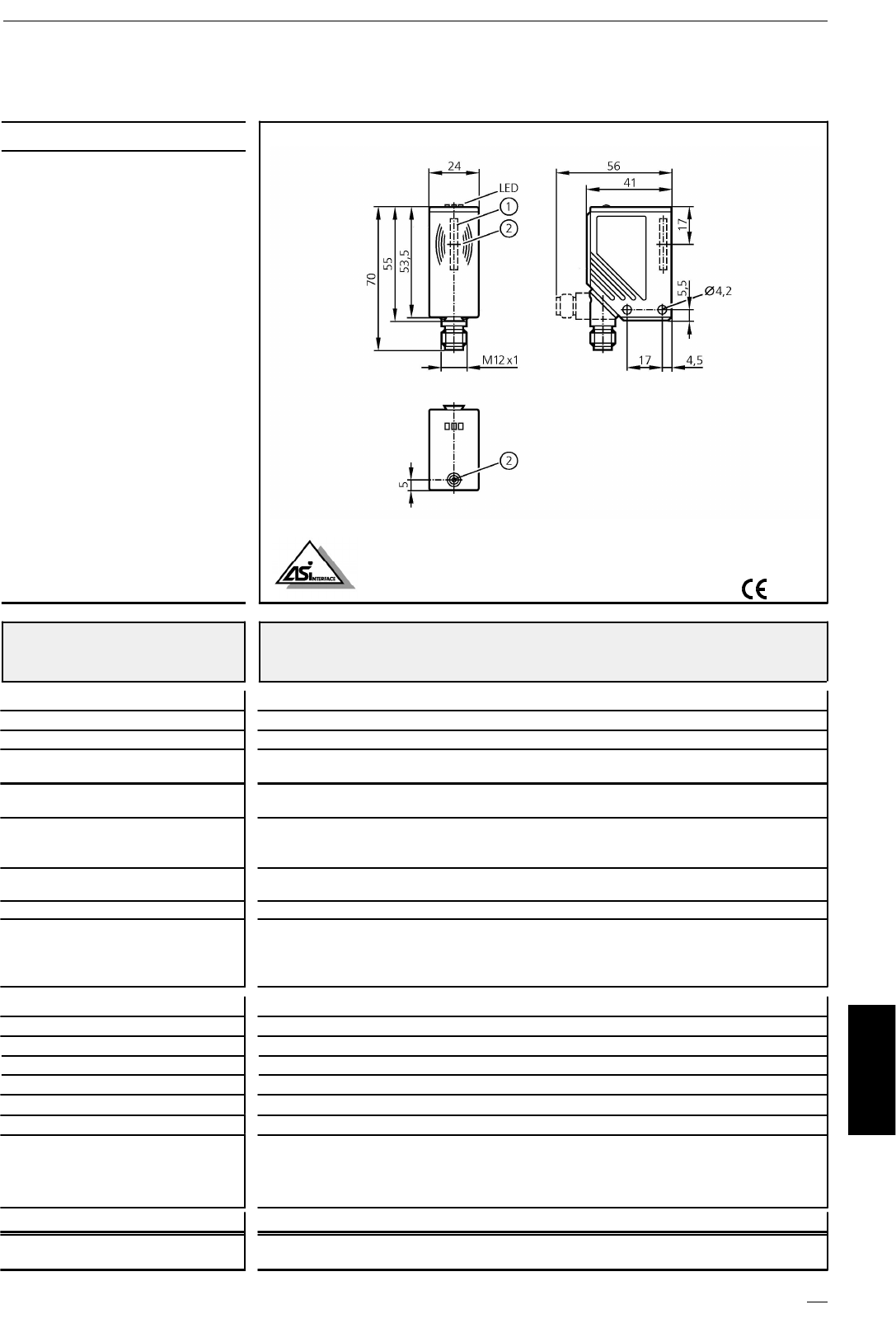
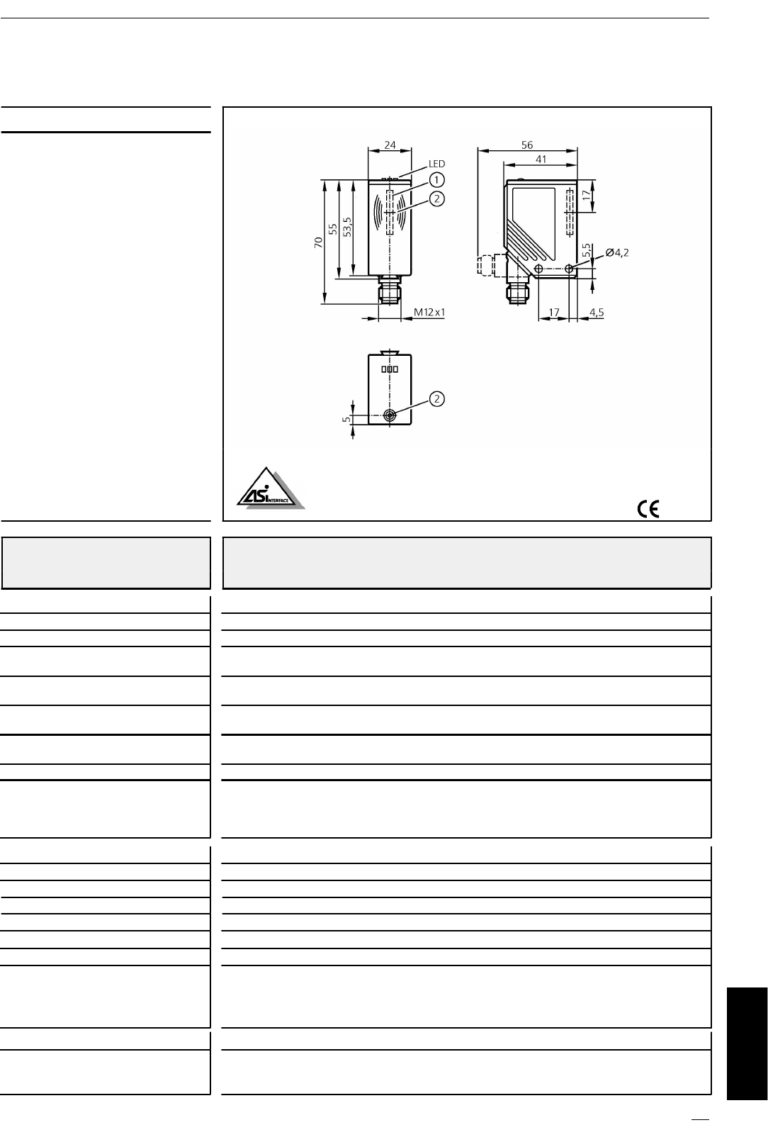
DTA100
Lese-/Schreibkopf
DTS/125/RW/AS/US
mit integriertem AS-i Slave
Profil 7.4
schwenkbare M12-Steckverbindung
1: integrierte Antenne, 2: TAG-Positioniermarke (Antennenmitte)
Einsatzbereich Erkennen von Objekten auf Transporteinrichtungen;
geeignet für Vorbeifahrgeschwindigkeiten bis 0,5 m/s
Elektrische Ausführung AS-i
Betriebsspannung [V] 26,5...31,6 DC (AS-i)
Stromaufnahme [mA] 50
Arbeitsfrequenz [kHz] 125
Vorbeifahrgeschwindigkeit * [m/s] Lesen: 0,5
Schreiben: nur statisch
Abstand zum ID-TAG * [mm] Lesen: 15 (bei 0,5 m/s); 20 (statisch)
Schreiben: 10 (statisch)
Abstand Lese-/Schreibkopf [mm] Lesen: 200
Lesen und Schreiben: 400
Datenbereitstellungszeit [ms] 70
Wertebereich 16 Bit (15 Bit ID-Wert, 1 Bit Meldungen)
Umgebungsbedingungen Umgebungstemperatur: -20...50 °C
Lagertemperatur: -25....80 °C
Vibration: 20 g; 10...2000 Hz
Schock: 50 g; 11 ms
Schutzart, Schutzklasse IP 67, III
AS-i-Profil 7.4
E/A-Konfiguration [Hex] 7
ID-Code [Hex] 4
AS-i-Zertifikat 71501
EMV EN 50295 (1999-03)
Gehäusewerkstoffe PA (Polyamid)
Anzeige 3 LED
grün: Betriebsspannung
gelb: TAG gelesen
rot: Fehler AS-i Datenkommunikation
Anschluss M12-Steckverbindung
Bemerkungen *) bezogen auf ID-TAG E80301 (Mitte Schraube)
Abstände zu anderen ID-TAGs siehe jeweiliges Datenblatt (E803xx)
ifm electronic gmbh • Teichstraße 4 • D-45127 Essen Technische bnderungen behalten wir uns ohne Ankündigung vor ! DE - DTA100 17.03.2006

The operating instructions
... apply to all DTA100 type units.
... are for authorised persons according to the EMC and low voltage directives.
... are part of the unit. They contain information about the correct handling of the
product. Read them before use to familiarise yourself with operating conditions,
installation and operation. Follow the safety instructions.
Contents
1. Safety instructions. . . . . . . . . . . . . . . . . . . . . . . . . . . . . . . . . . . . . . page 11
2. Function and features . . . . . . . . . . . . . . . . . . . . . . . . . . . . . . . . . . . page 12
3. Operating principle . . . . . . . . . . . . . . . . . . . . . . . . . . . . . . . . . . . . . page 12
4. Indicators . . . . . . . . . . . . . . . . . . . . . . . . . . . . . . . . . . . . . . . . . . . . page 13
5. Installation . . . . . . . . . . . . . . . . . . . . . . . . . . . . . . . . . . . . . . . . . . . page 13
6. Electrical connection . . . . . . . . . . . . . . . . . . . . . . . . . . . . . . . . . . . . page 14
7. The read/write head in the AS-i network
Basic setting . . . . . . . . . . . . . . . . . . . . . . . . . . . . . . . . . . . . . . . . . . page 15
Addressing . . . . . . . . . . . . . . . . . . . . . . . . . . . . . . . . . . . . . . . . . . . page 15
Analogue value representation. . . . . . . . . . . . . . . . . . . . . . . . . . . . . page 15
Assignment of the data bits. . . . . . . . . . . . . . . . . . . . . . . . . . . . . . . page 15
Coded value representation using the data bits D16...D1. . . . . . . . . . page 15
8. Additional functions to the AS-i profile 7.4 . . . . . . . . . . . . . . . . . . . . page 16
9. Approval of radio equipment . . . . . . . . . . . . . . . . . . . . . . . . . . . . . . page 16
10. EC declaration of conformity . . . . . . . . . . . . . . . . . . . . . . . . . . . . . . page 16
11. Maintenance, repair, disposal. . . . . . . . . . . . . . . . . . . . . . . . . . . . . . page 16
12. Technical data
Dimension . . . . . . . . . . . . . . . . . . . . . . . . . . . . . . . . . . . . . . . . . . . page 17
Travel speed . . . . . . . . . . . . . . . . . . . . . . . . . . . . . . . . . . . . . . . . . . page 17
Distance to the ID tag . . . . . . . . . . . . . . . . . . . . . . . . . . . . . . . . . . . page 17
Separation between read/write heads. . . . . . . . . . . . . . . . . . . . . . . . page 17
READ/WRITE HEAD FOR RF IDENTICFICATION SYSTEMS DTA100
10
1. Safety instructions
General
Follow the operating instructions. Non-observance of the instructions,
operation which is not in accordance with prescribed use, wrong installa-
tion or handling can affect the safety of people and machinery.
The installation and connection must comply with the applicable national and in-
ternational standards. Responsibility lies with the person installing the unit.
The unit must be installed, connected and put into operation by a qualified electri-
cian as the safe function of the unit and machinery is only guaranteed when in-
stallation is correctly carried out.
Disconnect the unit externally before handling it.
The unit must be supplied with an external direct voltage of 26.5…31.6 V accord-
ing to the criteria for safe extra-low voltage (SELV).
According to the technical specifications indicated in the instructions the unit can
be operated in a wide operating temperature range. Because of the additional in-
ternal heating the housing walls can have high perceptible temperatures when
touched in hot environments.
In case of malfunction of the unit or uncertainties please contact the manufacturer.
Tampering with the unit can seriously affect the safety of people and machinery.
This is not permitted and leads to an exclusion of liability and warranty.
Radio equipment
Do not transport and store any flammable gases, liquids or explosive
substances near the unit. In general, radio equipment must not be used
in the vicinity of petrol stations, fuel depots, chemical plants or blasting operations.
Electronic devices
Operation of the unit can affect the function of electronic devices that
are not correctly shielded. Disconnect the unit in the vicinity of medical
equipment. Please contact the manufacturer of the corresponding device or equip-
ment in case of problems.
FCC Notices (USA, Canada)
This device complies with Part 15 of the FCC Rules and with RSS-210 of Industry
Canada. Operation is subject to the following two conditions.
(1) this device my not cause harmful interference, and
(2) this device must accept any interference received, including interference that
may cause undesired operation.
Warning: Changes or modifications made to this equipment not expressly appro-
ved by ifm electronic gmbh may void the FCC authorization to operate this
equipment.
READ/WRITE HEAD FOR RF IDENTICFICATION SYSTEMS DTA100
11
ENGLISH
2. Function and features
•The DTA100 read/write head reads without contact data of RFID transponders
(ID tags) that conform to the system,
•converts them into digitally coded values
•and provides them to the AS-i control level
(AS-i master, controller or host).
Application examples:
•Material flow control in production lines
•Warehouse management by the automatic detection of stored products
•Tank management, order picking or product tracking
3. Operating principle
The ID tags are operated passively, i.e. without battery. The energy required for op-
eration is supplied by the read/write head.
The physical principle of the energy transfer is based on inductive coupling. The
antenna coil integrated in the read/write head generates a magnetic field which
partly penetrates the antenna coil of the ID tag.
A voltage is generated by induction that supplies the data carrier with energy.
READ/WRITE HEAD FOR RF IDENTICFICATION SYSTEMS DTA100
12
AS-i Master,
Controller oder Host
Impuls
Lese-/Schreibkopf DTA100
Energie
HF- und
Analog-
schaltung
Antenne
Anzeige
µController
und
AS-interface
ID-TAG
Daten
operating principle
AS-i master,
controller or host
read/write head DTA100 ID tag
display pulse
energy
energydata
HF and
analogue
circuit
µcontroller and
AS-interface
antenna
4. Indicators
5. Installation
Fixing is done using 2 M4 screws and nuts or an angle bracket. Information about
the available mounting accessories is given on our website at:
➔Data sheet direct ➔DTA100 ➔Accessories
When mounting several read/write heads adhere to the minimum distances be-
tween the systems ➔see 12. Technical data.
www.ifm-electronic.com
READ/WRITE HEAD FOR RF IDENTICFICATION SYSTEMS DTA100
13
ENGLISH
rot
gelb
grün
operation and error display at the read/write head
LED State Meaning
green ON operating voltage ok
yellow ON tag read
red ON error AS-i data communication
green
yellow
red
mounting examples
example
article no.
E20901
example
article no.
E20898

6. Electrical connection
Connect the read/write head to the AS-i network using the M12 connector.
Voltage is supplied via the AS-i network.
You can find a selection of sockets on our website at:
➔Data sheet direct ➔DTA100 ➔Accessories
Adhere to the distance between the AS-i cable and the housing of the read/write
head.
www.ifm-electronic.com
READ/WRITE HEAD FOR RF IDENTICFICATION SYSTEMS DTA100
14
ASI+
ASI
1
3
BN
BU
core colours of ifm sockets:
1 = BN (brown)
3 = BU (blue)
wiring
4
21
3
AA AA
AA
A
clear space read/write head ↔cable
A = 100 mm
7. The read/write head in the AS-i network
Basic setting
Addressing
The read/write head is addressed using an addressing unit (e.g. AC1144), the mas-
ter or the AS-i software of the host (the components must support the AS-i version
2.1).
Assign an address between 1 and 31.
Analogue value representation
For the AS-interface the read/write head is a slave having an analogue input with
the transmission protocol to the profile 7.4. If the master operates to the master
profile M3 or M4, it automatically detects the read/write head and supports the
profile 7.4.
For the analogue value transmission the profiles 7.3 and 7.4 are identical.
You can find the manual with details about the AS-i services to the profile 7.4 on
our website at:
➔Data sheet direct ➔DTA100 ➔Additional Data
Assignment of the data bits
In one transmission cycle the following data are transferred in data triples.
Additional information bits:
O = overflow bit (is set for the values 7FFF and 8000 hex, otherwise 0)
V = valid bit (is set for a valid value)
www.ifm-electronic.com
READ/WRITE HEAD FOR RF IDENTICFICATION SYSTEMS DTA100
15
ENGLISH
Parameters Values
I/O code [hex] 7
ID code [hex] 4
Extended ID2 code [hex] C
ID1 code for coded value [hex] F
Slave address (factory setting) 0
E3 E2 E1D16D15D14D13D12D11D10D9D8D7D6D5D4D3D2D1 O V
Extention
Bits
(statisch 0) User Data Bits
user data bits
extension
bits
(static 0)

Coded value representation using the data bits D16...D1
The ID value is represented as a signed 16-bit number.
Value 0 = no ID tag in the reading range or ID tag not detected.
8. Additional functions to the AS-i profile 7.4
Read ID string
Reading of AS-i slave information
Read diagnosis string
Reading of statistics of read/write operations
Read parameter string
(not implemented)
Write parameter string
Writing of data to the transponder
You can find the manual with details about the AS-i services to the profile 7.4 on
our website at:
➔Data sheet direct ➔DTA100 ➔Additional Data
9. Approval of radio equipment
Marking to R & TTE (Radio and Telecommunications Terminal Equipment)
CE identification number: CE 0682
Intended use: use in all EU countries
10. EC Declaration of Conformity
You can find the EC declaration of conformity on our website at:
➔Data sheet direct ➔DTA100 ➔Additional Data
11. Maintenance, repair, disposal
In case of correct use no maintenance and repair measures are necessary. Only the
manufacturer is allowed to repair the unit.
After use dispose of the unit in an environmentally friendly way in accordance
with the applicable national regulations.
www.ifm-electronic.com
www.ifm-electronic.com
READ/WRITE HEAD FOR RF IDENTICFICATION SYSTEMS DTA100
16
Range Decimal Hex
from to from to
Value range 0 32767 0 7FFF
Message range -1 -32768 FFFF 8000
12. Technical data
READ/WRITE HEAD FOR RF IDENTICFICATION SYSTEMS DTA100
17
ENGLISH
DTA100
Read/write head
DTS/125/RW/AS/US
with integrated AS-i slave
profile 7.4
rotatable M12 connector
1: integrated antenna , 2: tag positioning mark (middle of the antenna)
Application Detection of objects on conveying systems;
suitable for travel speeds up to 0.5 m/s
Electrical design AS-i
Operating voltage [V] 26.5...31.6 DC (AS-i)
Current consumption [mA] 50
Operating frequency [kHz] 125
Travel speed * [m/s] read: 0.5
write: only static
Distance to the ID tag * [mm] read: 15 (at 0.5 m/s); 20 (static)
write: 10 (static)
Separation between read/write
heads
[mm]
read: 200
read and write: 400
Data provision time [ms] 70
Value range 16 bits (15-bit ID value, 1-bit message)
Operating conditions operating temperature: -20...50 °C
storage temperature: -25....80 °C
vibration: 20 g; 10...2000 Hz
shock: 50 g; 11 ms
Protection IP 67, III
AS-i profile 7.4
I/O configuration [Hex] 7
ID code [Hex] 4
AS-i certificate 71501
EMC EN 50295 (1999-03)
Housing material PA (polyamide)
Display 3 LED
green: operating voltage
yellow: tag read
red: error AS-i data communication
Connection M12 connector
Remarks *) referred to the ID tag E80301 (middle of the screw)
For the distances to other ID tags see the respective data sheet (E803xx)
ifm electronic gmbh • Teichstraße 4 • D-45127 Essen We reserve the right to make technical alterations without prior notice . GB - DTA100 17.03.2006

La notice d'utilisation
... s'applique à tous les appareils de type DTA100.
... s'adresse à des personnes compétentes selon les directives
CEM
et basse tension.
... fait partie de l'appareil. Elle fournit des indications sur l'utilisation correcte du
produit. Lisez-la avant l'utilisation afin de vous familiariser avec les conditions envi-
ronnantes, l'installation et le fonctionnement. Respectez les consignes de sécurité.
Contenu
1. Consignes de sécurité. . . . . . . . . . . . . . . . . . . . . . . . . . . . . . . . . . . page 19
2. Caractéristiques et fonctionnement . . . . . . . . . . . . . . . . . . . . . . . . . page 20
3. Fonctionnement . . . . . . . . . . . . . . . . . . . . . . . . . . . . . . . . . . . . . . . page 20
4. Eléments de visualisation . . . . . . . . . . . . . . . . . . . . . . . . . . . . . . . . . page 21
5. Montage . . . . . . . . . . . . . . . . . . . . . . . . . . . . . . . . . . . . . . . . . . . . page 21
6. Raccordement électrique . . . . . . . . . . . . . . . . . . . . . . . . . . . . . . . . . page 22
7. La tête de lecture/écriture dans le réseau AS-i
Réglage de base . . . . . . . . . . . . . . . . . . . . . . . . . . . . . . . . . . . . . . . page 23
Adressage. . . . . . . . . . . . . . . . . . . . . . . . . . . . . . . . . . . . . . . . . . . . page 23
Représentation des valeurs analogiques . . . . . . . . . . . . . . . . . . . . . . page 23
Affectation des bits de données . . . . . . . . . . . . . . . . . . . . . . . . . . . . page 23
Représentation des valeurs codées par des bits de données D16…D1. page 23
8. Fonctions supplémentaires selon le profil AS-i 7.4 . . . . . . . . . . . . . . . page 24
9. Homologation des équipements radio . . . . . . . . . . . . . . . . . . . . . . . page 24
10. Déclaration de Conformité CE . . . . . . . . . . . . . . . . . . . . . . . . . . . . . page 24
11. Maintenance, réparation, élimination . . . . . . . . . . . . . . . . . . . . . . . . page 24
12. Données techniques
Dimension . . . . . . . . . . . . . . . . . . . . . . . . . . . . . . . . . . . . . . . . . . . page 25
Vitesse de passage . . . . . . . . . . . . . . . . . . . . . . . . . . . . . . . . . . . . . page 25
Distance du TAG . . . . . . . . . . . . . . . . . . . . . . . . . . . . . . . . . . . . . . . page 25
Distance entre têtes de lecture/écriture . . . . . . . . . . . . . . . . . . . . . . . page 25
TÊTE DE LECTURE/ÉCRITURE POUR IDENTIFICATION PAR RADIOFRÉQUENCE (RFID) DTA100
18
1. Consignes de sécurité
Généralité
Respectez les indications de la notice d'utilisation. Le non-respect des
consignes, l'emploi non conforme par rapport aux prescriptions, un
montage ou une manipulation incorrects peuvent porter atteinte à la sécurité des
personnes et des installations.
Le montage et le raccordement doivent être conformes aux normes nationales et
internationales en vigueur. La personne qui installe l'appareil en est responsable.
L'appareil doit être monté, raccordé et mis en service par un électricien qualifié car
seul un montage correct garantit le bon fonctionnement de l'appareil et de l'instal-
lation.
Mettre l'appareil hors tension avant de le manipuler.
L'appareil doit être alimenté en tension continue de 26,5 à 31,6 V selon les critères
de la basse tension de sécurité (TBTS).
L'appareil peut fonctionner dans une grande plage de températures ambiantes se-
lon la spécification technique fournie dans la notice. En ambiance chaude, en rai-
son de l'échauffement interne supplémentaire, les parois du boîtier peuvent mon-
ter à des températures importantes.
En cas de mauvais fonctionnement de l'appareil ou en cas de doute, veuillez
contacter le fabricant. Les interventions sur l'appareil peuvent avoir des consé-
quences graves pour la sécurité des personnes et des installations. Elles ne sont pas
autorisées et aboutissent à une exclusion de responsabilité et de garantie.
Equipements radio
Ne transportez et stockez pas de gaz, liquides inflammables ou de sub-
stances explosives près de l'appareil. En général, les équipements radio
ne doivent pas être utilisés à proximité de stations d'essence, de dépôts de carbu-
rants, d'usines chimiques ou de lieux où il existe des risques de détonation.
Appareils électroniques
L'emploi de l'appareil peut affecter le bon fonctionnement des appareils
électroniques qui ne sont pas correctement blindés. Mettez l'appareil
hors tension à proximité des équipements médicaux. En cas de problèmes, veuillez
contacter le fabricant de l'appareil ou de l'équipement correspondant.
Homologation FCC
Des informations correspondantes concernant cette homologation du matériel ra-
dio aux Etats-Unis / au Canada se trouvent dans la partie anglaise "1. Safety In-
struction".
TÊTE DE LECTURE/ÉCRITURE POUR IDENTIFICATION PAR RADIOFRÉQUENCE (RFID) DTA100
19
FRANÇAIS
2. Caractéristiques et fonctionnement
•La tête de lecture/écriture DTA100 lit sans contact les données des étiquettes
électroniques RFID (TAG) qui sont compatibles avec le système,
•les convertit en valeurs codées numériquement
•et les met à la disposition du bus de communication AS-i (maître AS-i ,
passerelle AS-i vers un autre bus de terrain, système de commande).
Exemples d'applications :
•Contrôle du flux de manutention dans des lignes de production ;
•Gestion de magasin grâce à une détection automatique des produits stockés ;
•Gestion de cuves, préparation de commandes ou traçabilité des produits
fabriqués.
3. Fonctionnement
Les TAG sont passifs, l'énergie nécessaire à leur fonctionnement étant fournie par
la tête de lecture/écriture.
Le principe physique du transfert de l'énergie repose sur le couplage inductif. La
bobine de l'antenne intégrée dans la tête de lecture/écriture génère un champ ma-
gnétique qui pénètre en partie la bobine de l'antenne du TAG.
Une tension est générée par induction qui alimente le support de données en
énergie.
TÊTE DE LECTURE/ÉCRITURE POUR IDENTIFICATION PAR RADIOFRÉQUENCE (RFID) DTA100
20
AS-i Master,
Controller oder Host
Impuls
Lese-/Schreibkopf DTA100
Energie
HF- und
Analog-
schaltung
Antenne
Anzeige
µController
und
AS-interface
ID-TAG
Daten
principe de fonctionnement
maître AS-i,
système de commande
tête de lecture/écriture DTA100 TAG
affichage impulsion
énergie
données
circuit HF
et
analogique
µcontrôleur
et AS-interface
antenne
4. Eléments de visualisation
5. Montage
La fixation se fait par 2 vis M4 et écrous ou par une équerre. Vous trouverez des
informations sur les accessoires de montage disponibles sur notre site web à :
➔Fiche technique ➔DTA100 ➔Accessoires
En cas de montage de plusieurs têtes de lecture/écriture respectez les distances mi-
nimales entre les systèmes ➔voir 12. Données techniques.
www.ifm-electronic.com
TÊTE DE LECTURE/ÉCRITURE POUR IDENTIFICATION PAR RADIOFRÉQUENCE (RFID) DTA100
21
FRANÇAIS
rot
gelb
grün
indication de fonctionnement
et d'erreurs sur la tête de lecture/écriture
LED Etat Signification
verte ALLUMEE tension d'alimentation ok
jaune ALLUMEE étiquette lue
rouge ALLUMEE erreur de communication des données AS-i
verte
jaune
rouge
exemples de montage
exemple
référence
E20901
exemple
référence
E20898
6. Raccordement électrique
Raccordez la tête de lecture/écriture au réseau AS-i via le connecteur M12. L'ali-
mentation en tension s'effectue via le réseau AS-i.
Vous trouvez une sélection de connecteurs femelles sur notre site web à :
➔Fiche technique ➔DTA100 ➔Accessoires
Respectez la distance entre le câble AS-i et le boîtier de la tête de lecture/d'écritu-
re.
www.ifm-electronic.com
TÊTE DE LECTURE/ÉCRITURE POUR IDENTIFICATION PAR RADIOFRÉQUENCE (RFID) DTA100
22
ASI+
ASI
1
3
BN
BU
couleurs des fils conducteurs des
connecteurs femelles ifm :
1 = BN (brun)
3 = BU (bleu)
schéma de branchement
4
21
3
AA AA
AA
A
espace dégagé tête de lecture/écriture ↔câble AS-i
A = 100 mm
7. La tête de lecture/écriture dans le réseau AS-i
Réglages de base
Adressage
La tête de lecture/écriture est adressée à l'aide d'une unité d'adressage (par ex.
AC1144), le maître AS-i ou le logiciel AS-i du système de commande (les compo-
sants doivent être compatibles avec la version AS-i V 2.1).
Affectez une adresse entre 1 et 31.
Représentation des valeurs analogiques
La tête de lecture / écriture est considérée comme un esclave AS-i à une entrée
analogique utilisant le protocole de transmission suivant le profil AS-i 7.4. Si le
maître AS-i travaille selon le profil maître M3 ou M4, il détecte automatiquement
la tête de lecture/écriture et est compatible avec le profil 7.4.
Pour la transmission de valeurs analogiques les profils 7.3 et 7.4 sont identiques.
Vous trouvez le manuel donnant un descriptif détaillé de la communication AS-i
selon le profil 7.4 sur notre site web à :
➔Fiche technique ➔DTA100 ➔Information sur le Produit
Affectation des bits de données
Dans un cycle de transmission les données suivantes sont transmises par triplets de
données :
Bits d'information supplémentaires :
O = bit de débordement (est mis à 1 pour les valeurs 7FFF et 8000 hexa, sinon 0)
V = bit valable (est mis à 1 pour une valeur valable)
www.ifm-electronic.com
TÊTE DE LECTURE/ÉCRITURE POUR IDENTIFICATION PAR RADIOFRÉQUENCE (RFID) DTA100
23
FRANÇAIS
Profil AS-i / Adresse Valeurs
Code E/S [hexa] 7
Code ID [hexa] 4
Code ID2 [hexa] C
Code ID1 [hexa] F
Adresse d'esclave (réglage usine) 0
E3 E2 E1D16D15D14D13D12D11D10D9D8D7D6D5D4D3D2D1 O V
Extention
Bits
(statisch 0) User Data Bits
bits de données utilisateurs
bits
d'extension
(0 statique)

Représentation des valeurs stockées par des bits de données D16…D1
La valeur numérique stockée dans le TAG est représentée par un nombre de 16
bits avec signe.
Valeur 0 = aucun TAG dans la plage de lecture ou TAG non détecté.
8. Fonctions supplémentaires selon le profil AS-i 7.4
Read ID string (lecture de la chaîne ID)
Lecture des informations venant de l'esclave AS-i
Read diagnosis string (lecture de la chaîne de diagnostic)
Lecture de statistiques des opérations de lecture/écriture
Read parameter string (lecture de la chaîne de paramètres)
(non implémenté)
Write parameter string (écriture de la chaîne de paramètres)
Ecriture de données sur le TAG
Vous trouvez le manuel donnant un descriptif détaillé des possibilités du profil 7.4
sur notre site web à :
➔Fiche technique ➔DTA100 ➔Information sur le Produit
9. Homologation des équipements radio
Marquage selon R & TTE (Radio and Telecommunications Terminal Equipment =
équipements radioélectriques et équipements terminaux de télécommunications)
Numéro d'identification CE : CE 0682
Utilisation prévue : utilisation dans tous les états de l'UE
10. Déclaration de Conformité CE
Vous trouvez la déclaration de conformité CE sur notre site web à :
➔Fiche technique ➔DTA100 ➔Information sur le Produit
11. Maintenance, réparation, élimination
En cas de fonctionnement correct, il n'est pas nécessaire de prendre des mesures
relatives à la maintenance et la réparation. L'appareil ne doit être réparé que par le
fabricant.
Assurez une élimination écologique de l'appareil après son usage selon les rè-
glements nationaux en vigueur.
www.ifm-electronic.com
www.ifm-electronic.com
TÊTE DE LECTURE/ÉCRITURE POUR IDENTIFICATION PAR RADIOFRÉQUENCE (RFID) DTA100
24
Plage Décimal Hexa
de àde à
Plage de valeurs 0 32767 0 7FFF
Plage de messages -1 -32768 FFFF 8000
12. Données techniques
TÊTE DE LECTURE/ÉCRITURE POUR IDENTIFICATION PAR RADIOFRÉQUENCE (RFID) DTA100
25
FRANÇAIS
DTA100
Tête de lecture/écriture RFID
DTS/125/RW/AS/US
avec esclave AS-i intégré
profil 7.4
connecteur M12 orientable
1: antenne intégrée, 2: repère TAG (milieu d'antenne)
Application Détection d'objets sur des systèmes de convoyage ;
appropriée pour des vitesses de passage jusqu'à 0,5 m/s
Technologie AS-i
Tension d'alimentation [V] 26,5...31,6 DC (AS-i)
Consommation [mA] 50
Fréquence de fonctionnement [kHz] 125
Vitesse de passage * [m/s] lecture : 0,5
écriture : seulement statique
Distance du TAG * [mm] lecture : 15 (à 0,5 m/s); 20 (statique)
écriture : 10 (statique)
Distance entre têtes de
lecture/écriture [mm]
lecture : 200
lecture et écriture : 400
Temps de fourniture des données
[ms]
70
Plage de valeurs 16 bits (valeur ID de 15 bits + 1 bit de signe)
Conditions d'utilisation température ambiante : -20...50 °C
température de stockage : -25....80 °C
vibration : 20 g; 10...2000 Hz
choc : 50 g; 11 ms
Protection IP 67, III
Profil AS-i 7.4
Configuration E/S [hexa] 7
Code ID [hexa] 4
Certificat AS-i 71501
CEM EN 50295 (1999-03)
Matières boîtier PA (polyamide)
Indication 3 LED
verte : tension d'alimentation
j
aune : TAG lu
rouge : erreur de communication des données AS -i
Raccordement embase M12
Remarques *) par rapport au TAG E80301 (milieu de la vis)
Pour les distances avec d'autres TAG voir la fiche technique correspondante
(E803xx)
ifm electronic gmbh • Teichstraße 4 • D-45127 Essen Nous nous réservons le droit de modifier les données techniques sans préavis . FR - DTA100 17.03.2006
Technische Änderungen behalten wir uns ohne vorherige Ankündigung vor. • We reserve the right to make technical alterations without prior notice. • Nous nous réservons le droit de modifier les données techniques sans préavis.