ip access KU02ZZS GSM/GPRS/EDGE/AMR picocellular base station operating at 1900MHz. User Manual NGSM INST 300 nanoBTS Install v2 1
ip.access ltd GSM/GPRS/EDGE/AMR picocellular base station operating at 1900MHz. NGSM INST 300 nanoBTS Install v2 1
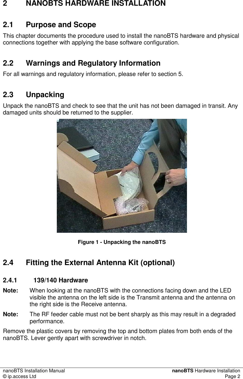
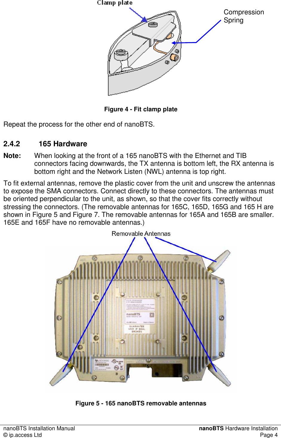
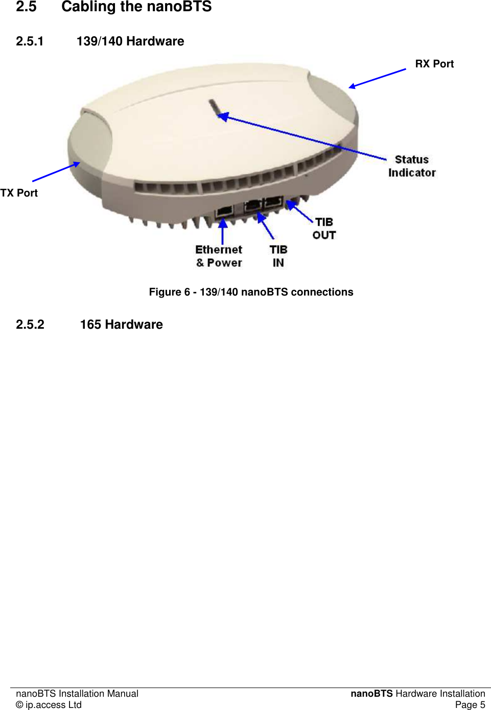
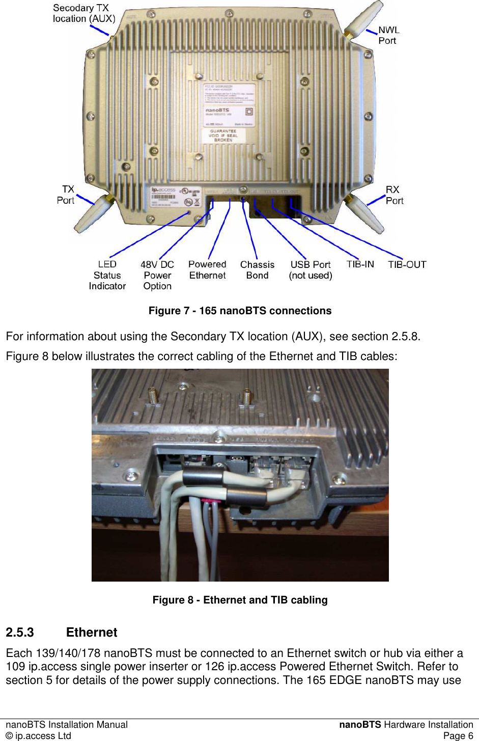
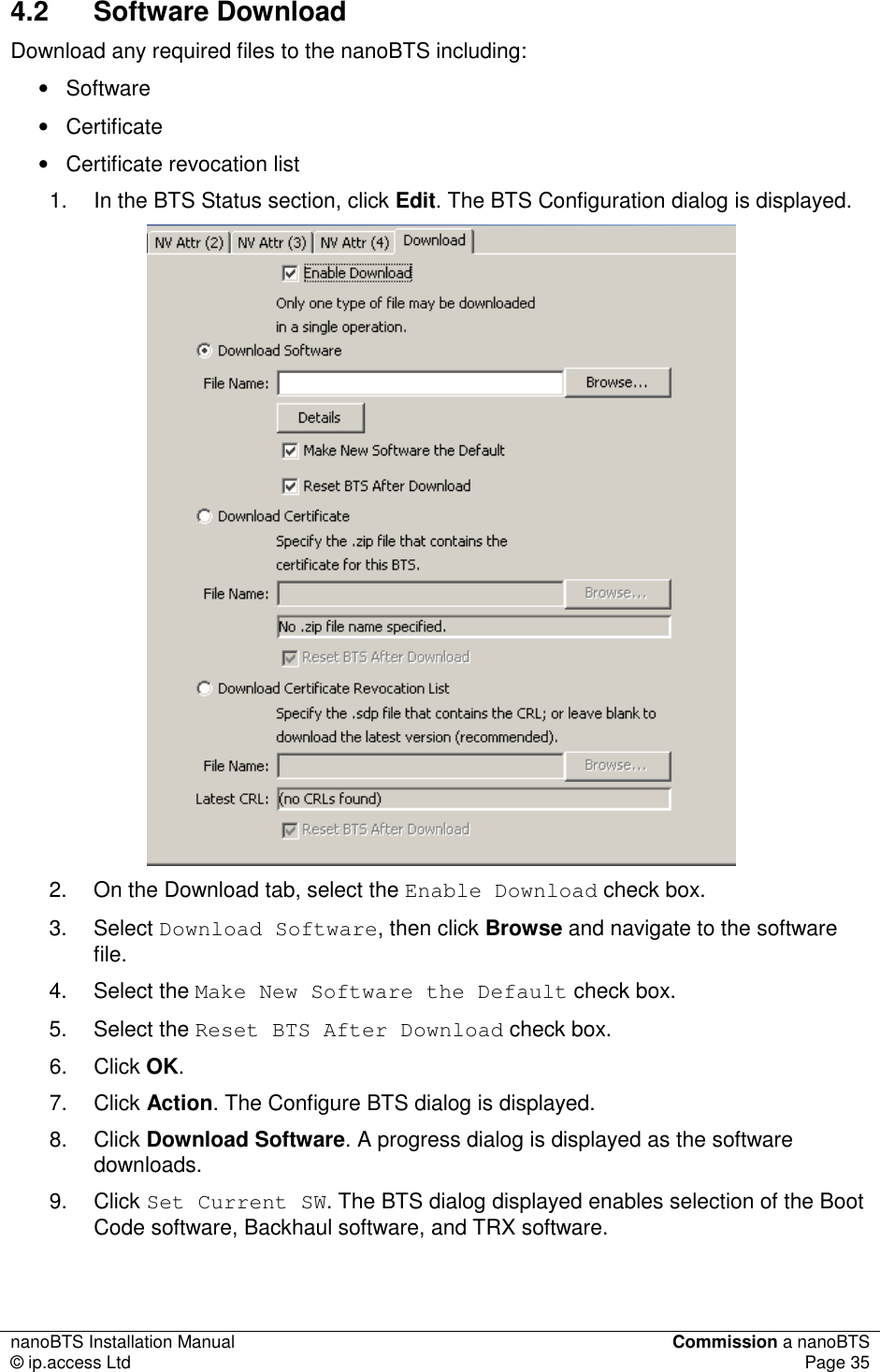
Contents
- 1. Installation Manual
- 2. Product Description
Installation Manual
![nanoBTS Installation Manual Introduction © ip.access Ltd Page 1 1 INTRODUCTION The ip.access nanoBTS is an indoor pico-class BTS offering a standard Um radio interface to GSM mobiles. The nanoBTS is available in 850MHz, 900MHz, 1800MHz, and 1900MHz band versions. 1.1 Overview This document provides the reader with all the necessary information required to install the ip.access nanoBTS. The document provides step-by-step instructions for the hardware installation, PSU Installation, and configuration steps required to bring the nanoBTS into service. 1.2 nanoBTS Installation Overview The principal activities for installing and commissioning a nanoBTS are: • Install the nanoBTS hardware • Install the power supply • Commission the nanoBTS with BTS Installer • Inform the NOC the nanoBTS is ready for network configuration 1.3 Related Information [GST_120] nanoGSM System Planning Manual (NGSM_GST_120] [GST_300] nanoBTS Product Description (NGSM_GST_300) [OPM_300] nanoBTS Operations Manual (NGSM_OPM_300) 1.4 Terminology NOC Network Operations Centre DHCP Dynamic Host Configuration Protocol](https://usermanual.wiki/ip-access/KU02ZZS.Installation-Manual/User-Guide-1105685-Page-6.png)

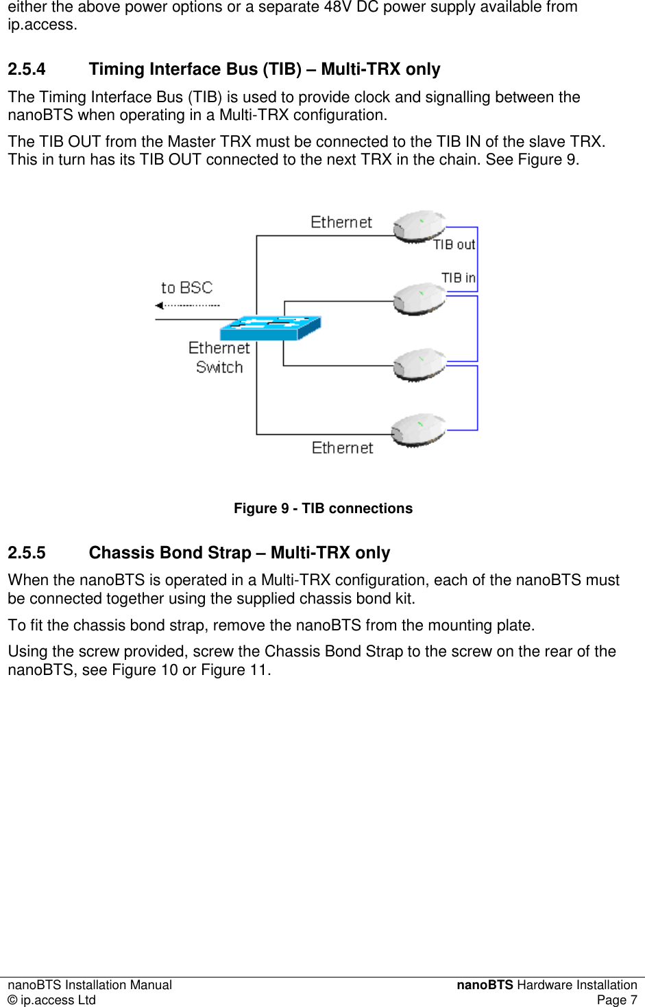
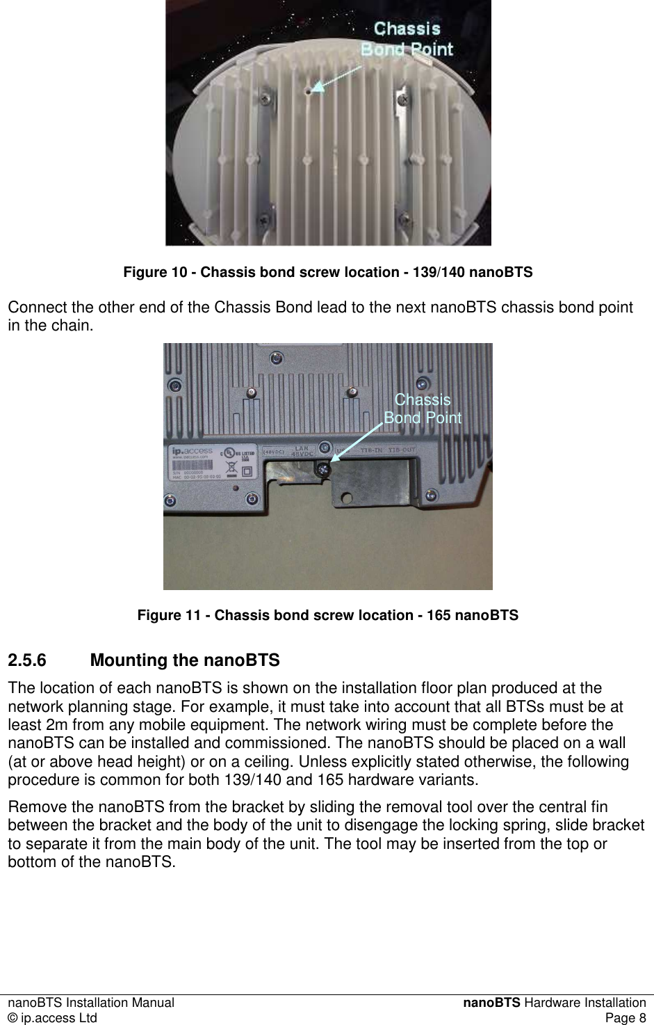
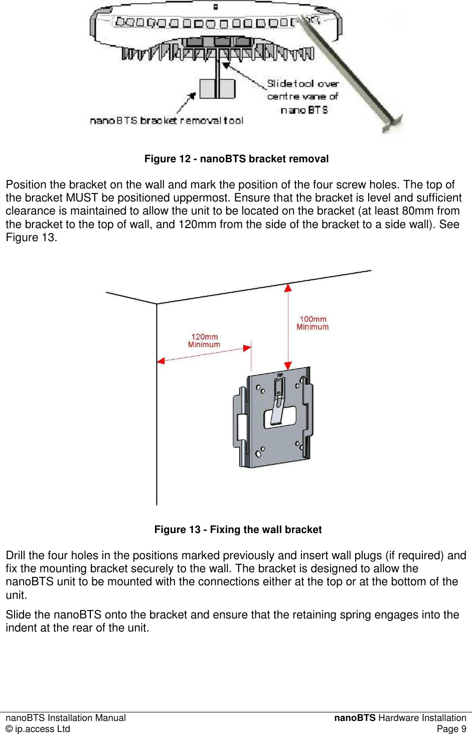
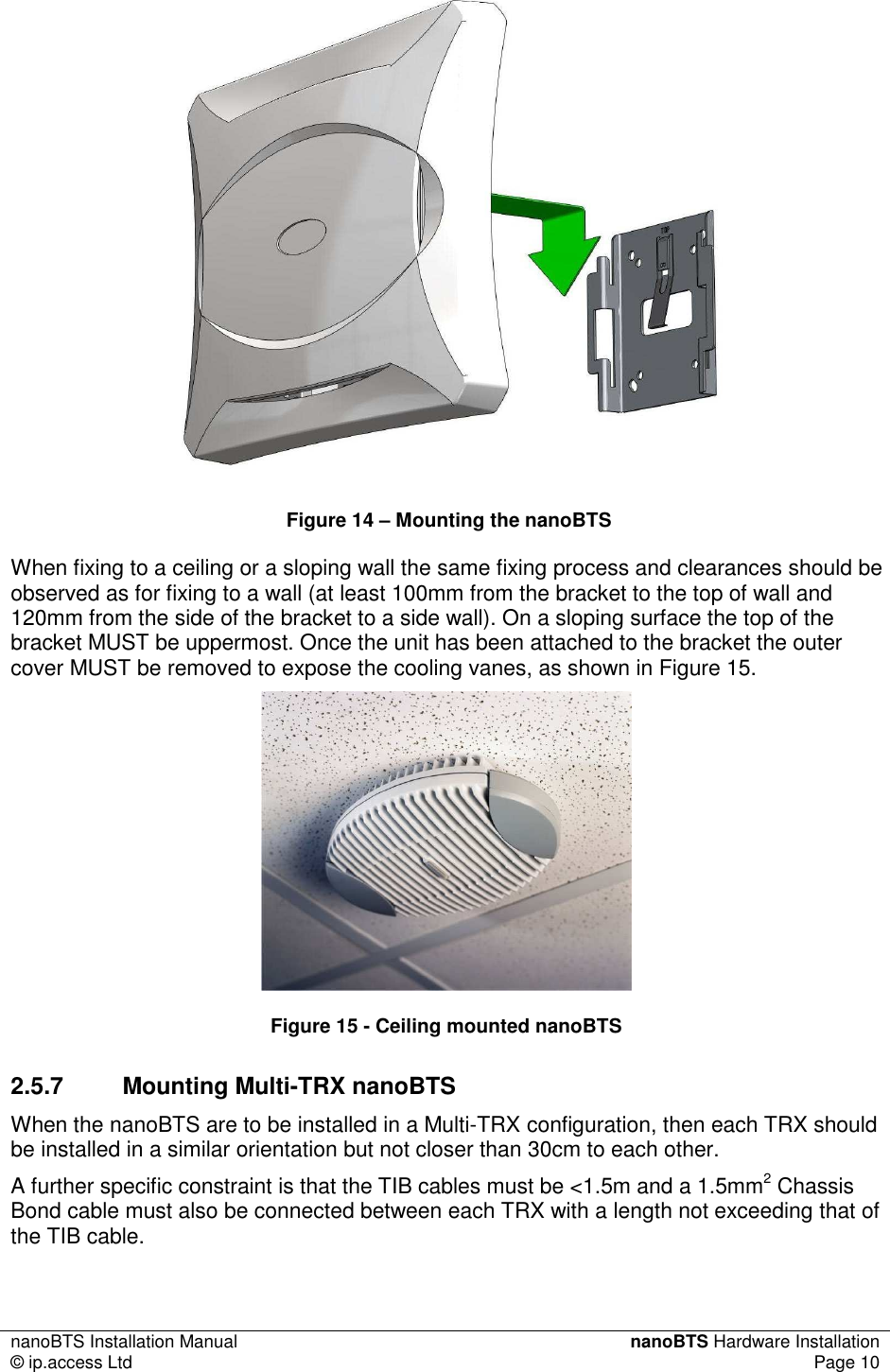
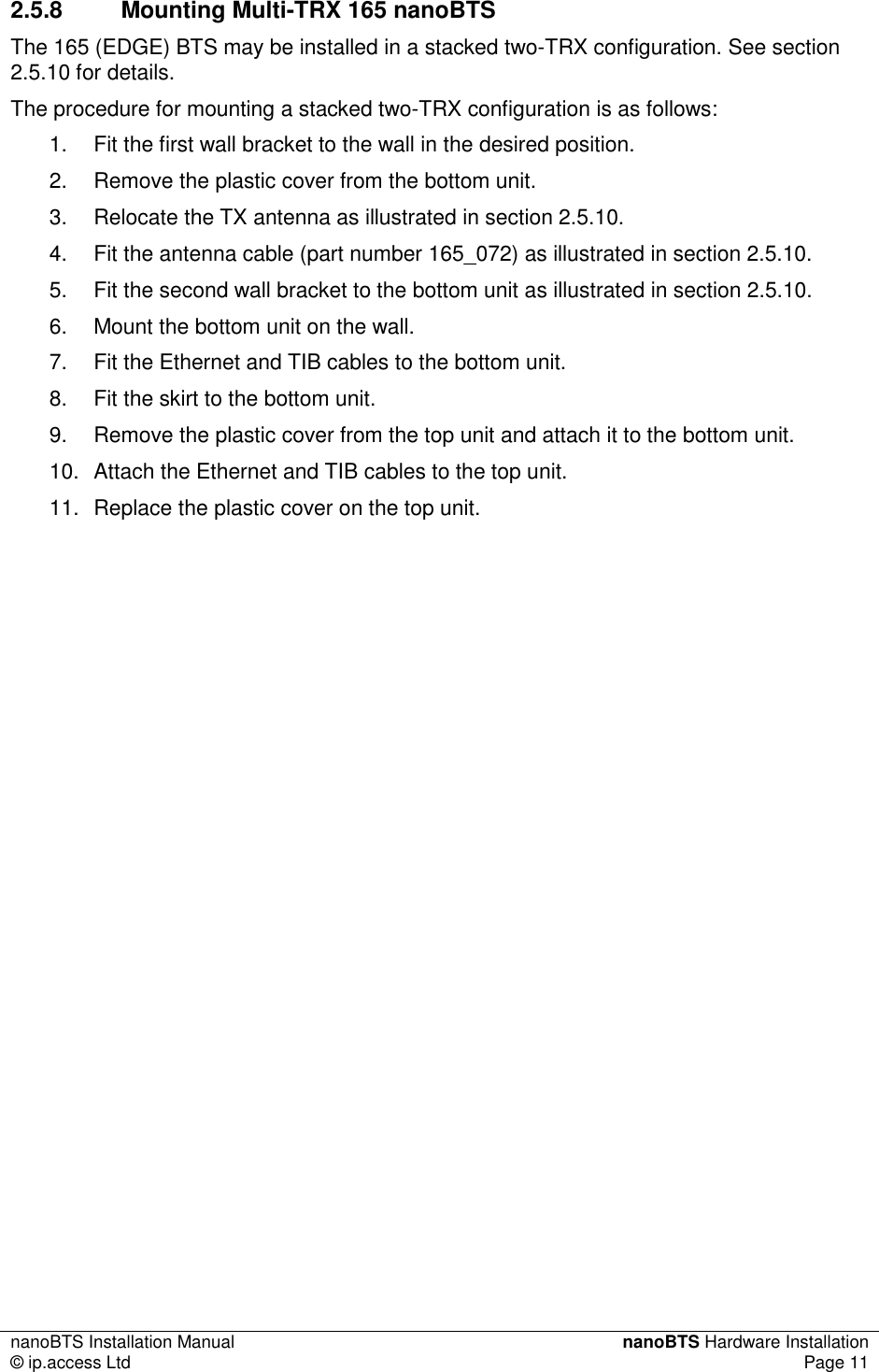
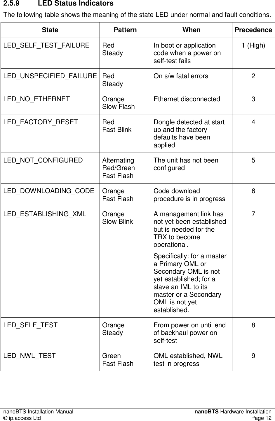
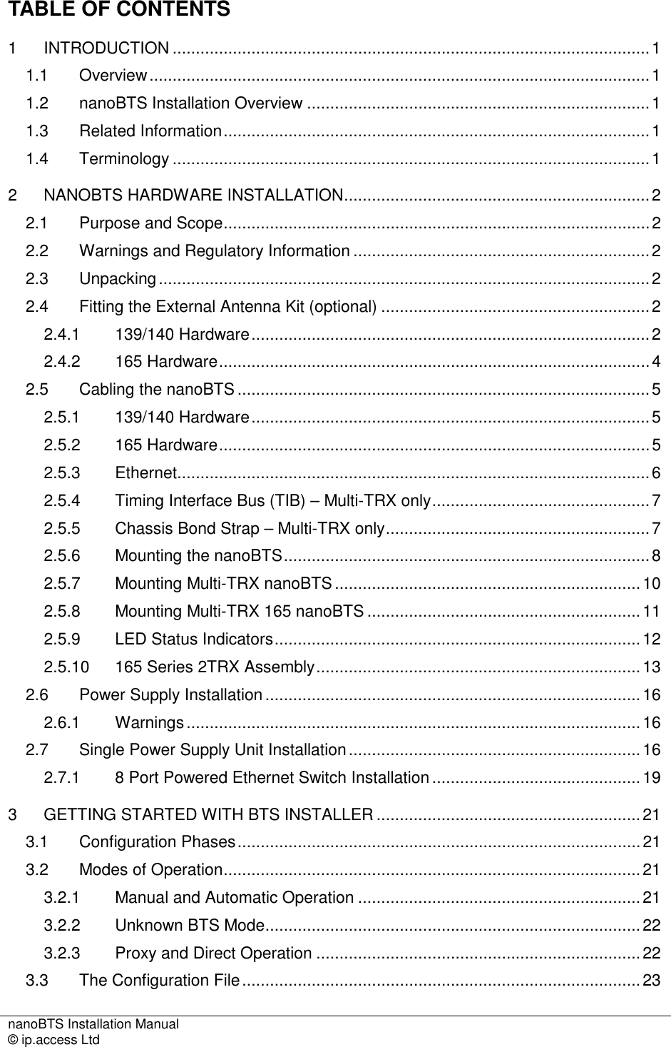
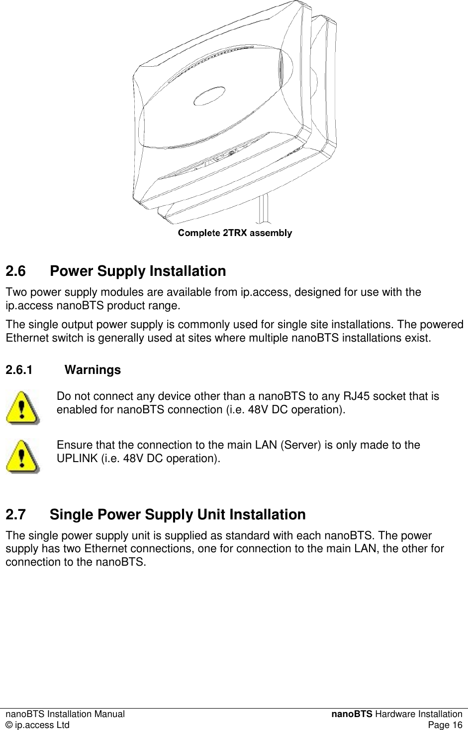
![nanoBTS Installation Manual nanoBTS Hardware Installation © ip.access Ltd Page 13 LED_OCXO_CALIBRATION Alternating Green/Orange Slow Blink The unit is in the fast calibrating state [SYNC] 10 LED_NOT_TRANSMITTING Green Slow Flash The radio carrier is not being transmitted 11 LED_OPERATIONAL Green Steady Default condition if none of the above apply 12 (Low) 2.5.10 165 Series 2TRX Assembly](https://usermanual.wiki/ip-access/KU02ZZS.Installation-Manual/User-Guide-1105685-Page-18.png)
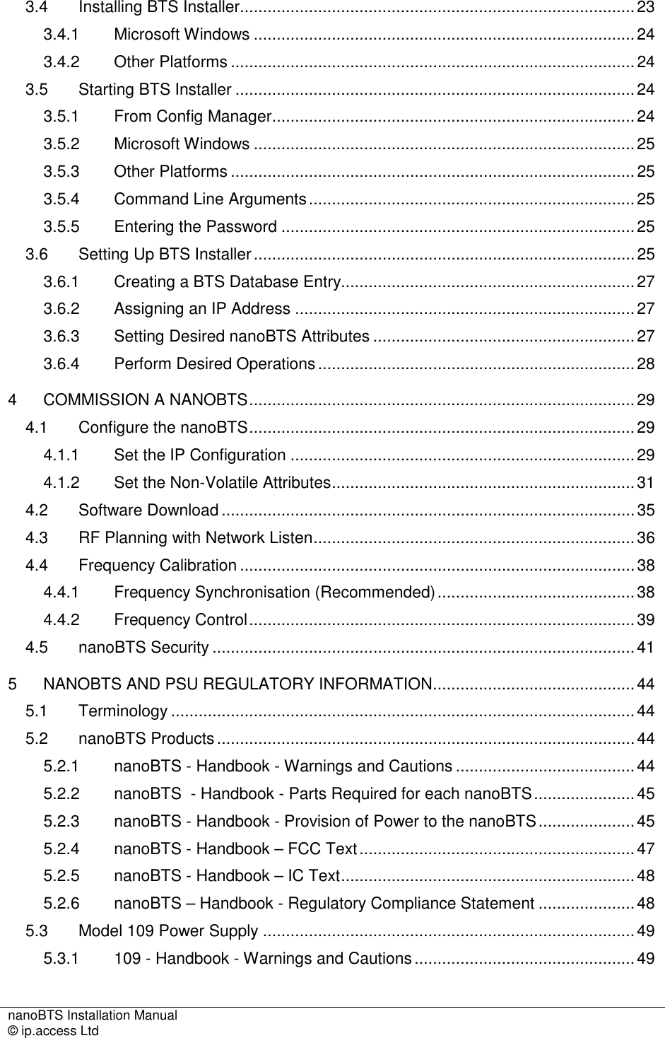
![nanoBTS Installation Manual Getting Started with BTS Installer © ip.access Ltd Page 23 and return the replies. In such configurations BTS Installer communicates with the nanoBTSs in proxy mode. There are two different types of proxy that might be present on a BSC: a Primary OML Proxy and a Secondary OML Proxy. Which can be used depends on the network configuration. Direct connection or proxy mode is indicated to the user in the status bar at the bottom of the user interface. A later section explains how to start BTS Installer in proxy mode, and lists the limitations of BTS Installer whilst in proxy mode. 3.3 The Configuration File BTS Installer can be given the information it needs in the following ways: • in a configuration file • via the graphical user interface • via some combination of a configuration file and the graphical user interface The configuration file is a text file which can be created with any text editor and which contains definitions for: • default values for BTS attributes • the nanoBTSs to be operated on • attributes to be set for the BTSs • the DHCP server’s IP address pool It is not necessary to create a configuration file for most uses of BTS Installer, as almost all necessary information can be entered via the graphical user interface. The only exception is that a BTS Database entry for the “Unknown BTS” cannot be entered via the GUI and can only be entered via the configuration file. At any point it is possible to save the current state of the BTS Database and IP address pool to a configuration file; this can be done even if no configuration file has been loaded and all data has been entered via the GUI. This allows you to do the following: • entering configuration information via the GUI • saving the configuration information to a new configuration file • loading the configuration file in a later run of BTS Installer In other words, you can use BTS Installer itself to create a configuration file for later use, instead of using a text editor. See 'Configuration File Reference' in [OPM_300] for details of the syntax of the configuration file. 3.4 Installing BTS Installer This section contains information about installing BTS Installer, preparing it for use, and performing an operation on a nanoBTS. BTS Installer is a Java application. It requires that the Sun J2SE Java Runtime Environment be installed: version 1.5 is required (there is no particular requirement as to](https://usermanual.wiki/ip-access/KU02ZZS.Installation-Manual/User-Guide-1105685-Page-28.png)
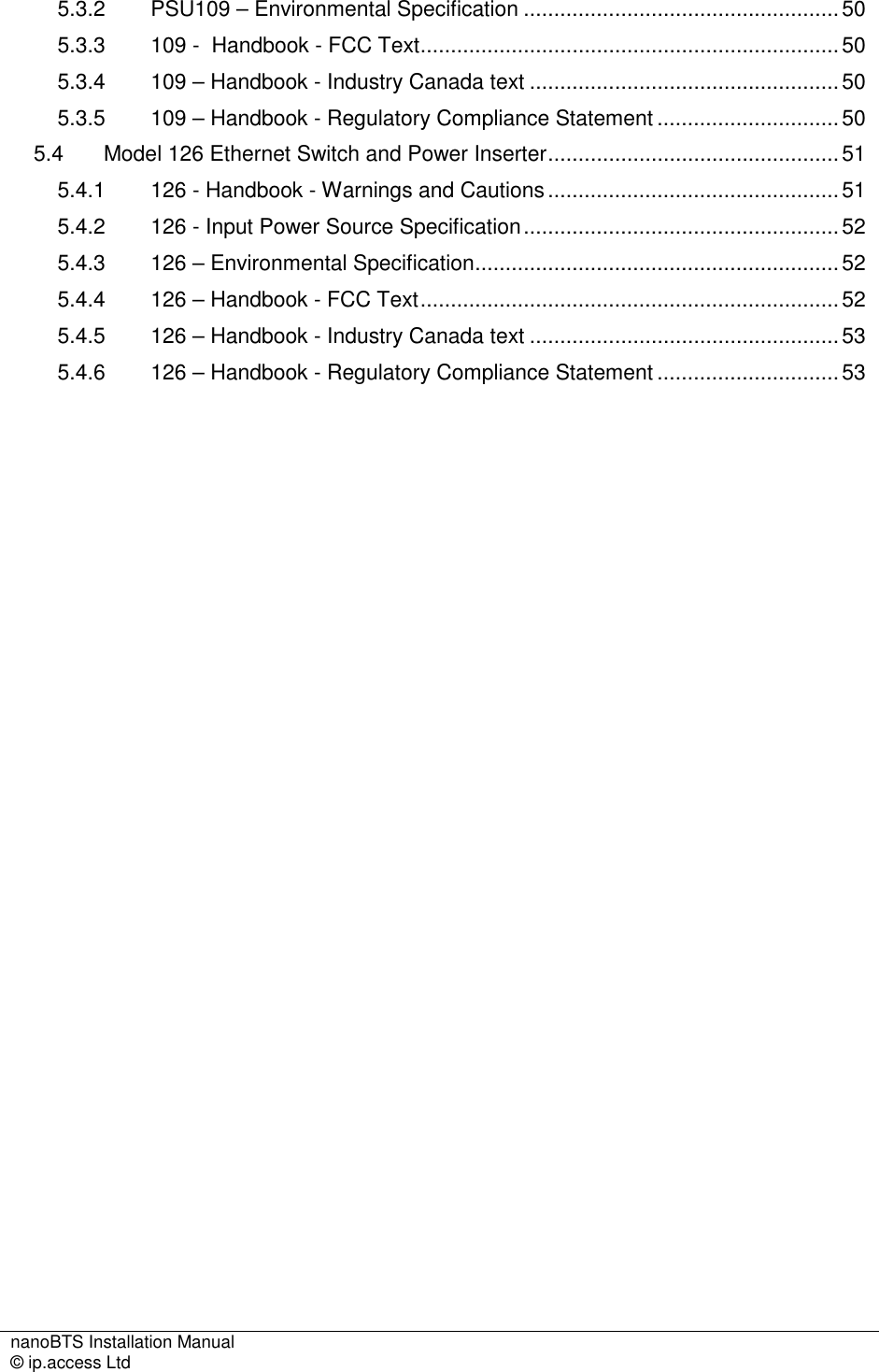
![nanoBTS Installation Manual Getting Started with BTS Installer © ip.access Ltd Page 24 which subversion of 1.5 is used). The J2SE Java Runtime Environment is available, with installation instructions, from Sun’s Java web-site (http://www.java.sun.com). 3.4.1 Microsoft Windows 3.4.1.1 Pre-Installation Requirements • Local craft terminal for the installation running Windows 2000 SP2 or Windows XP SP2 • CD-ROM drive or Internet connection • Java run time environment version 1.5.0_07 or later 3.4.1.2 Installing the BTS Installer Package The estimated installation time for the product is 5 minutes. 1. Login to the PC ensuring that you have Administrator privileges. 2. Using Windows Explorer, browse to the directory, either on the CD-ROM or network drive where the BTS Installer application is located. 3. Double click on the Icon for BTS Installer: Note: For actual revision levels of each package, please refer to the System Release Note. 4. Follow the on-screen instructions to complete the installation. If it is desired to use BTS Installer to make secure (SSL) connections to nanoBTSs then perform the following additional steps: 5. Install the Aladdin eToken run time environment. Aladin e-Token RTE requires that the computer is running Windows 2000 SP2 or Windows XP SP2. 6. Plug the eToken (a hardware device which contains a certificate and private key for BTS Installer) into a USB port. 3.4.2 Other Platforms Details of installing BTS Installer on platforms other than Microsoft Windows are beyond the scope of this document. However in most cases copying the file BtsInstaller.jar to a suitable directory will be adequate. On platforms other than Windows there is no support for making SSL connections to the nanoBTS. 3.5 Starting BTS Installer 3.5.1 From Config Manager BTS Installer can be started from Config Manager, in which case it will be pre-populated with some nanoBTSs selected in Config Manager and will operate in proxy mode. See 'Starting BTS Installer from Config Manager' in [OPM_300] for details.](https://usermanual.wiki/ip-access/KU02ZZS.Installation-Manual/User-Guide-1105685-Page-29.png)
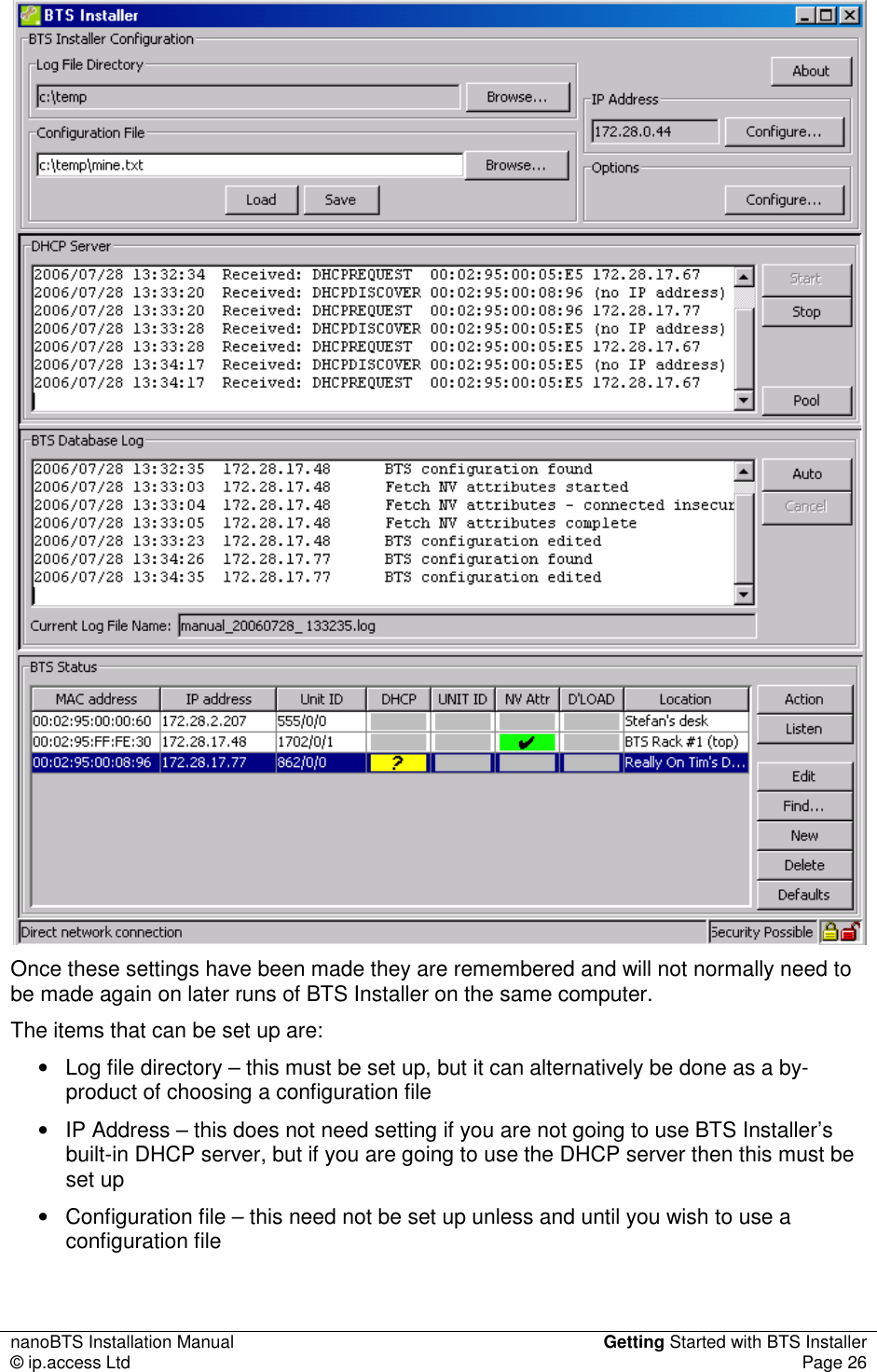
![nanoBTS Installation Manual Getting Started with BTS Installer © ip.access Ltd Page 25 3.5.2 Microsoft Windows BTS Installer can be started by double clicking the desktop item or by selecting the menu entry in the normal way. 3.5.3 Other Platforms Details of starting BTS Installer on platforms other than Microsoft Windows are beyond the scope of this document. However on platforms with a command line interface a command like the following is likely to be useful: java -jar BtsInstaller.jar 3.5.4 Command Line Arguments On all platforms, additional command line arguments can be used to specify that BTS Installer should run in proxy mode, and/or to specify the IP addresses and optionally Unit IDs of some nanoBTSs for which BTS Installer should create BTS Database entries. See 'Command Line Parameters' in [OPM_300] for details of the command line arguments. Depending on the platform, it will be possible to set up a shortcut or a script to run BTS Installer with any desired set of command line arguments. 3.5.5 Entering the Password When BTS Installer starts, if an eToken containing a certificate and private key is found it will prompt the user for the password for the eToken. The password should be entered if it is desired to make secure (SSL) connections to nanoBTSs; if only insecure connections are wanted then the password request may be cancelled. See section 4.5 for further details. 3.6 Setting Up BTS Installer The BTS Installer Configuration section of the user interface contains some settings that tell BTS Installer how it is to operate. Until some of these settings have been made most of the buttons on the user interface will be disabled and most of BTS Installer’s functionality will be unavailable.](https://usermanual.wiki/ip-access/KU02ZZS.Installation-Manual/User-Guide-1105685-Page-30.png)
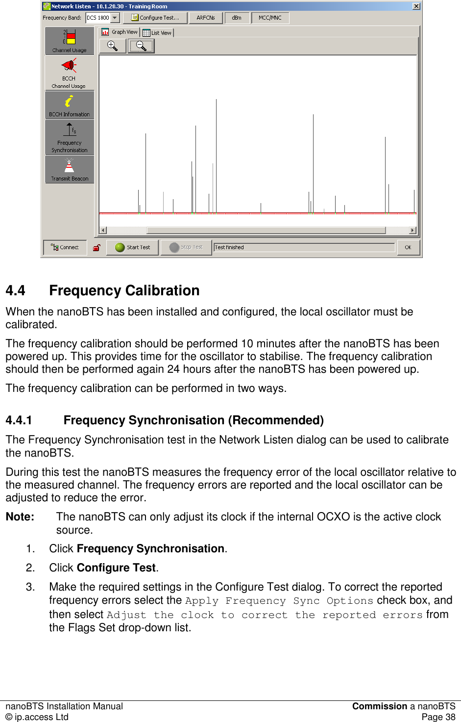
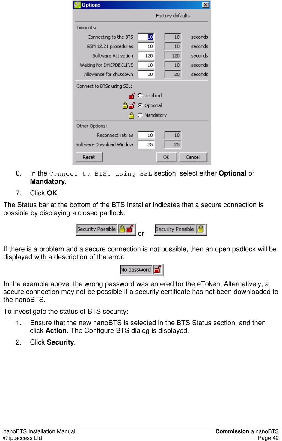
![nanoBTS Installation Manual Commission a nanoBTS © ip.access Ltd Page 37 2. In the Frequency Band drop-down list, ensure that the correct GSM band is selected. 3. Click Connect. It will take approximately 90 seconds to create the connection from BTS Installer to the nanoBTS. When the connection is complete, the message Ready to run test is displayed in the status pane at the bottom of the dialog and the Status Indicator on the nanoBTS will flash green. 4. Click Channel Usage on the left side of the dialog. The options on the left side of the dialog are the Network Listen tests. 5. Click Start Test. 6. When the Channel Usage test is complete, click BCCH Channel Usage. 7. Click Configure Test. 8. Make the required settings in the Configure Test dialog. The BCCH Channel Usage test reports on channels containing a GSM frequency correction and synchronisation burst. For more information see [OPM_300]. 9. Click Start Test. When the test is complete, the results are displayed in a graph.](https://usermanual.wiki/ip-access/KU02ZZS.Installation-Manual/User-Guide-1105685-Page-42.png)