ip access KU02ZZS GSM/GPRS/EDGE/AMR picocellular base station operating at 1900MHz. User Manual NGSM INST 300 nanoBTS Install v2 1
ip.access ltd GSM/GPRS/EDGE/AMR picocellular base station operating at 1900MHz. NGSM INST 300 nanoBTS Install v2 1
Contents
- 1. Installation Manual
- 2. Product Description
Installation Manual

The world's most deployed picocell
ip.access Ltd
Building 2020
Cambourne Business Park
Cambourne
Cambridgeshire
CB23 6DW
United Kingdom
nanoBTS Installation Manual
NGSM_INST_300 2.1 CP

REVISION HISTORY
Version Change Summary Date Author
0.1 First draft 04 Mar 2008
INITS
0.2 Added hardware installation and commissioning chapters
12 Nov 2008
MB3
0.3 Implemented review corrections 11 Nov 2008
ZN1
1.0 Released 21 Nov 2008
ZN1
1.1 Added minimum MS-BTS distance
Updated OS requirements
13 Jan 2009 ZN1
2.0 Released 19 Jan 2009 ZN1
2.1 Added 165E/F/G/H information – CP DRAFT 30 Apr 2009 ZN1
DOCUMENT APPROVAL
Approved by e-mail.
The information contained in this document is commercially confidential and must
not be disclosed to third parties without prior consent.

nanoBTS Installation Manual
© ip.access Ltd
TABLE OF CONTENTS
1
INTRODUCTION .......................................................................................................1
1.1
Overview............................................................................................................1
1.2
nanoBTS Installation Overview ..........................................................................1
1.3
Related Information............................................................................................1
1.4
Terminology .......................................................................................................1
2
NANOBTS HARDWARE INSTALLATION..................................................................2
2.1
Purpose and Scope............................................................................................2
2.2
Warnings and Regulatory Information ................................................................2
2.3
Unpacking..........................................................................................................2
2.4
Fitting the External Antenna Kit (optional) ..........................................................2
2.4.1
139/140 Hardware......................................................................................2
2.4.2
165 Hardware.............................................................................................4
2.5
Cabling the nanoBTS .........................................................................................5
2.5.1
139/140 Hardware......................................................................................5
2.5.2
165 Hardware.............................................................................................5
2.5.3
Ethernet......................................................................................................6
2.5.4
Timing Interface Bus (TIB) – Multi-TRX only...............................................7
2.5.5
Chassis Bond Strap – Multi-TRX only.........................................................7
2.5.6
Mounting the nanoBTS...............................................................................8
2.5.7
Mounting Multi-TRX nanoBTS..................................................................10
2.5.8
Mounting Multi-TRX 165 nanoBTS ...........................................................11
2.5.9
LED Status Indicators...............................................................................12
2.5.10
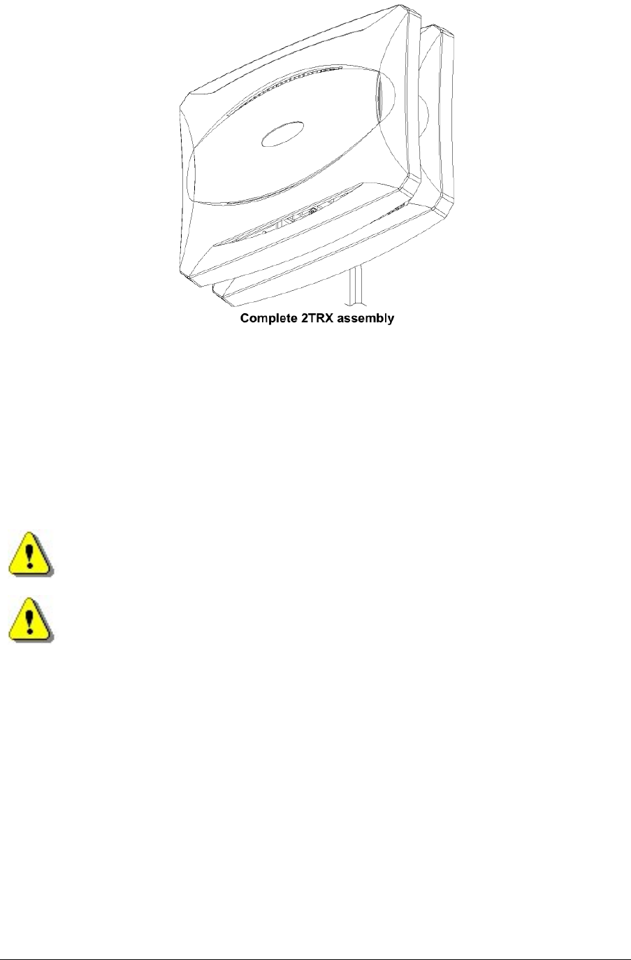
165 Series 2TRX Assembly......................................................................13
2.6
Power Supply Installation.................................................................................16
2.6.1
Warnings..................................................................................................16
2.7
Single Power Supply Unit Installation...............................................................16
2.7.1
8 Port Powered Ethernet Switch Installation .............................................19
3
GETTING STARTED WITH BTS INSTALLER .........................................................21
3.1
Configuration Phases.......................................................................................21
3.2
Modes of Operation..........................................................................................21
3.2.1
Manual and Automatic Operation .............................................................21
3.2.2
Unknown BTS Mode.................................................................................22
3.2.3
Proxy and Direct Operation ......................................................................22
3.3
The Configuration File......................................................................................23

nanoBTS Installation Manual
© ip.access Ltd
3.4
Installing BTS Installer......................................................................................23
3.4.1
Microsoft Windows ...................................................................................24
3.4.2
Other Platforms ........................................................................................24
3.5
Starting BTS Installer .......................................................................................24
3.5.1
From Config Manager...............................................................................24
3.5.2
Microsoft Windows ...................................................................................25
3.5.3
Other Platforms ........................................................................................25
3.5.4
Command Line Arguments.......................................................................25
3.5.5
Entering the Password .............................................................................25
3.6
Setting Up BTS Installer...................................................................................25
3.6.1
Creating a BTS Database Entry................................................................27
3.6.2
Assigning an IP Address ..........................................................................27
3.6.3
Setting Desired nanoBTS Attributes .........................................................27
3.6.4
Perform Desired Operations.....................................................................28
4
COMMISSION A NANOBTS....................................................................................29
4.1
Configure the nanoBTS....................................................................................29
4.1.1
Set the IP Configuration ...........................................................................29
4.1.2
Set the Non-Volatile Attributes..................................................................31
4.2
Software Download..........................................................................................35
4.3
RF Planning with Network Listen......................................................................36
4.4
Frequency Calibration......................................................................................38
4.4.1
Frequency Synchronisation (Recommended)...........................................38
4.4.2
Frequency Control....................................................................................39
4.5
nanoBTS Security ............................................................................................41
5
NANOBTS AND PSU REGULATORY INFORMATION............................................44
5.1
Terminology .....................................................................................................44
5.2
nanoBTS Products...........................................................................................44
5.2.1
nanoBTS - Handbook - Warnings and Cautions ....................................... 44
5.2.2
nanoBTS - Handbook - Parts Required for each nanoBTS......................45
5.2.3
nanoBTS - Handbook - Provision of Power to the nanoBTS.....................45
5.2.4
nanoBTS - Handbook – FCC Text............................................................47
5.2.5
nanoBTS - Handbook – IC Text................................................................48
5.2.6
nanoBTS – Handbook - Regulatory Compliance Statement .....................48
5.3
Model 109 Power Supply .................................................................................49
5.3.1
109 - Handbook - Warnings and Cautions................................................49

nanoBTS Installation Manual
© ip.access Ltd
5.3.2
PSU109 – Environmental Specification ....................................................50
5.3.3
109 - Handbook - FCC Text.....................................................................50
5.3.4
109 – Handbook - Industry Canada text ...................................................50
5.3.5
109 – Handbook - Regulatory Compliance Statement ..............................50
5.4
Model 126 Ethernet Switch and Power Inserter................................................51
5.4.1
126 - Handbook - Warnings and Cautions................................................51
5.4.2
126 - Input Power Source Specification....................................................52
5.4.3
126 – Environmental Specification............................................................52
5.4.4
126 – Handbook - FCC Text.....................................................................52
5.4.5
126 – Handbook - Industry Canada text ...................................................53
5.4.6
126 – Handbook - Regulatory Compliance Statement ..............................53

nanoBTS Installation Manual Introduction
© ip.access Ltd Page 1
1 INTRODUCTION
The ip.access nanoBTS is an indoor pico-class BTS offering a standard Um radio interface
to GSM mobiles. The nanoBTS is available in 850MHz, 900MHz, 1800MHz, and 1900MHz
band versions.
1.1 Overview
This document provides the reader with all the necessary information required to install the
ip.access nanoBTS. The document provides step-by-step instructions for the hardware
installation, PSU Installation, and configuration steps required to bring the nanoBTS into
service.
1.2 nanoBTS Installation Overview
The principal activities for installing and commissioning a nanoBTS are:
• Install the nanoBTS hardware
• Install the power supply
• Commission the nanoBTS with BTS Installer
• Inform the NOC the nanoBTS is ready for network configuration
1.3 Related Information
[GST_120] nanoGSM System Planning Manual (NGSM_GST_120]
[GST_300] nanoBTS Product Description (NGSM_GST_300)
[OPM_300] nanoBTS Operations Manual (NGSM_OPM_300)
1.4 Terminology
NOC Network Operations Centre
DHCP Dynamic Host Configuration Protocol
nanoBTS Installation Manual nanoBTS Hardware Installation
© ip.access Ltd Page 2
2 NANOBTS HARDWARE INSTALLATION
2.1 Purpose and Scope
This chapter documents the procedure used to install the nanoBTS hardware and physical
connections together with applying the base software configuration.
2.2 Warnings and Regulatory Information
For all warnings and regulatory information, please refer to section 5.
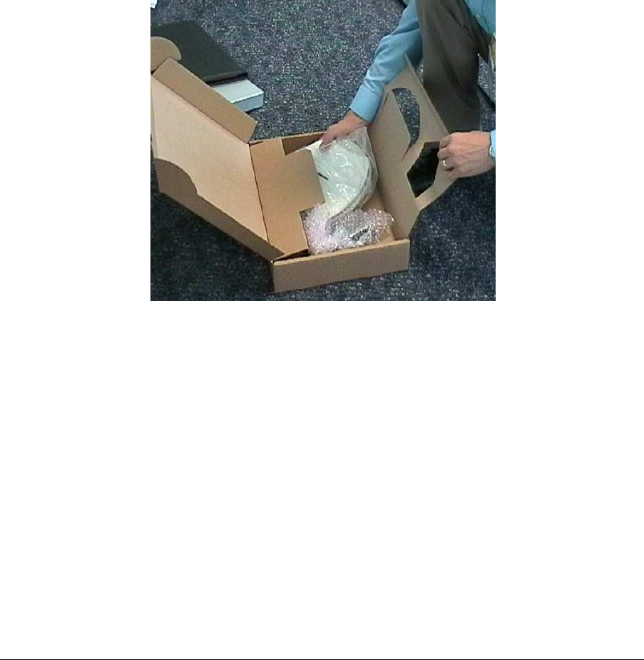
2.3 Unpacking
Unpack the nanoBTS and check to see that the unit has not been damaged in transit. Any
damaged units should be returned to the supplier.
Figure 1 - Unpacking the nanoBTS
2.4 Fitting the External Antenna Kit (optional)
2.4.1 139/140 Hardware
Note: When looking at the nanoBTS with the connections facing down and the LED
visible the antenna on the left side is the Transmit antenna and the antenna on
the right side is the Receive antenna.
Note: The RF feeder cable must not be bent sharply as this may result in a degraded
performance.
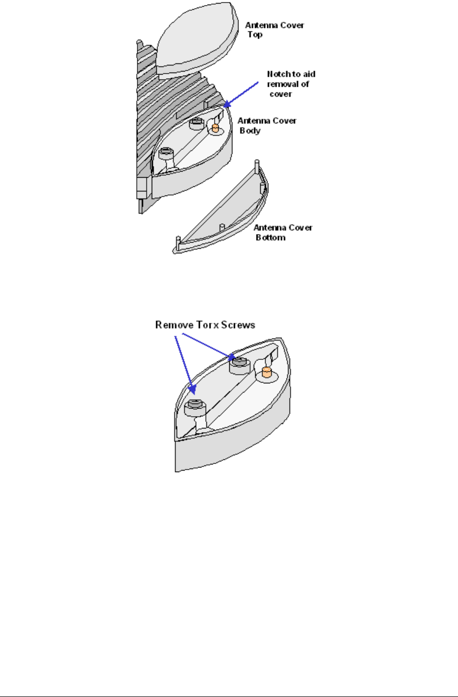
Remove the plastic covers by removing the top and bottom plates from both ends of the
nanoBTS. Lever gently apart with screwdriver in notch.
nanoBTS Installation Manual nanoBTS Hardware Installation
© ip.access Ltd Page 3
Figure 2 - Removal of antenna covers
Remove the antenna cover body, by unscrewing the two Torx T20 retaining screws.
Figure 3 - Removal of antenna cover body
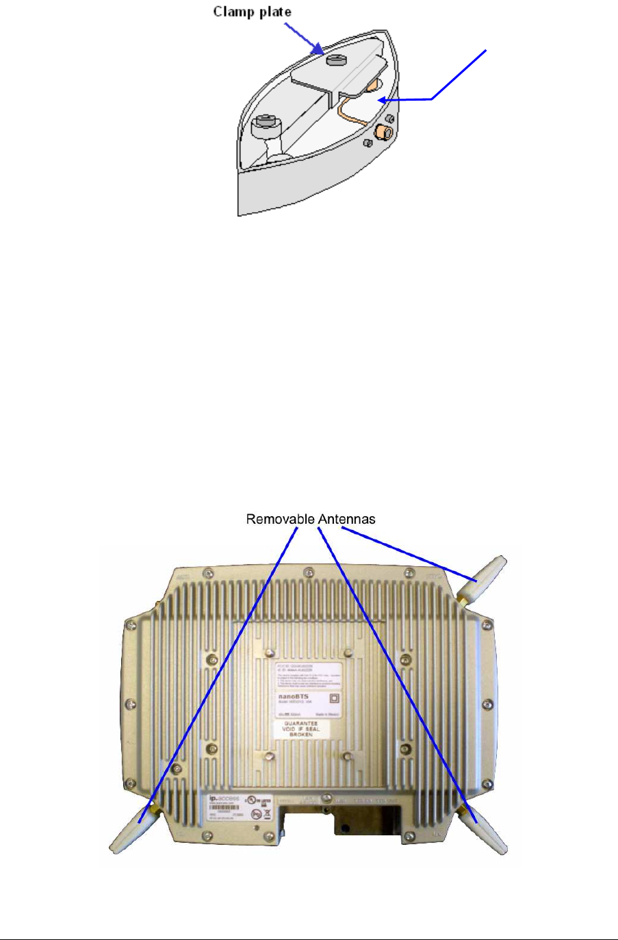
Fit the replacement antenna cover body ensuring that the feeder cable connector fits into
the antenna. Note that one cover only fits the receiver whilst the other fits the transmitter.
Fit the clamp as shown below and second Torx screw, then replace top and bottom
covers.
nanoBTS Installation Manual nanoBTS Hardware Installation
© ip.access Ltd Page 4
Figure 4 - Fit clamp plate
Repeat the process for the other end of nanoBTS.
2.4.2 165 Hardware
Note: When looking at the front of a 165 nanoBTS with the Ethernet and TIB
connectors facing downwards, the TX antenna is bottom left, the RX antenna is
bottom right and the Network Listen (NWL) antenna is top right.
To fit external antennas, remove the plastic cover from the unit and unscrew the antennas
to expose the SMA connectors. Connect directly to these connectors. The antennas must
be oriented perpendicular to the unit, as shown, so that the cover fits correctly without
stressing the connectors. (The removable antennas for 165C, 165D, 165G and 165 H are
shown in Figure 5 and Figure 7. The removable antennas for 165A and 165B are smaller.
165E and 165F have no removable antennas.)
Figure 5 - 165 nanoBTS removable antennas
Compression
Spring
nanoBTS Installation Manual nanoBTS Hardware Installation
© ip.access Ltd Page 5
2.5 Cabling the nanoBTS
2.5.1 139/140 Hardware
Figure 6 - 139/140 nanoBTS connections
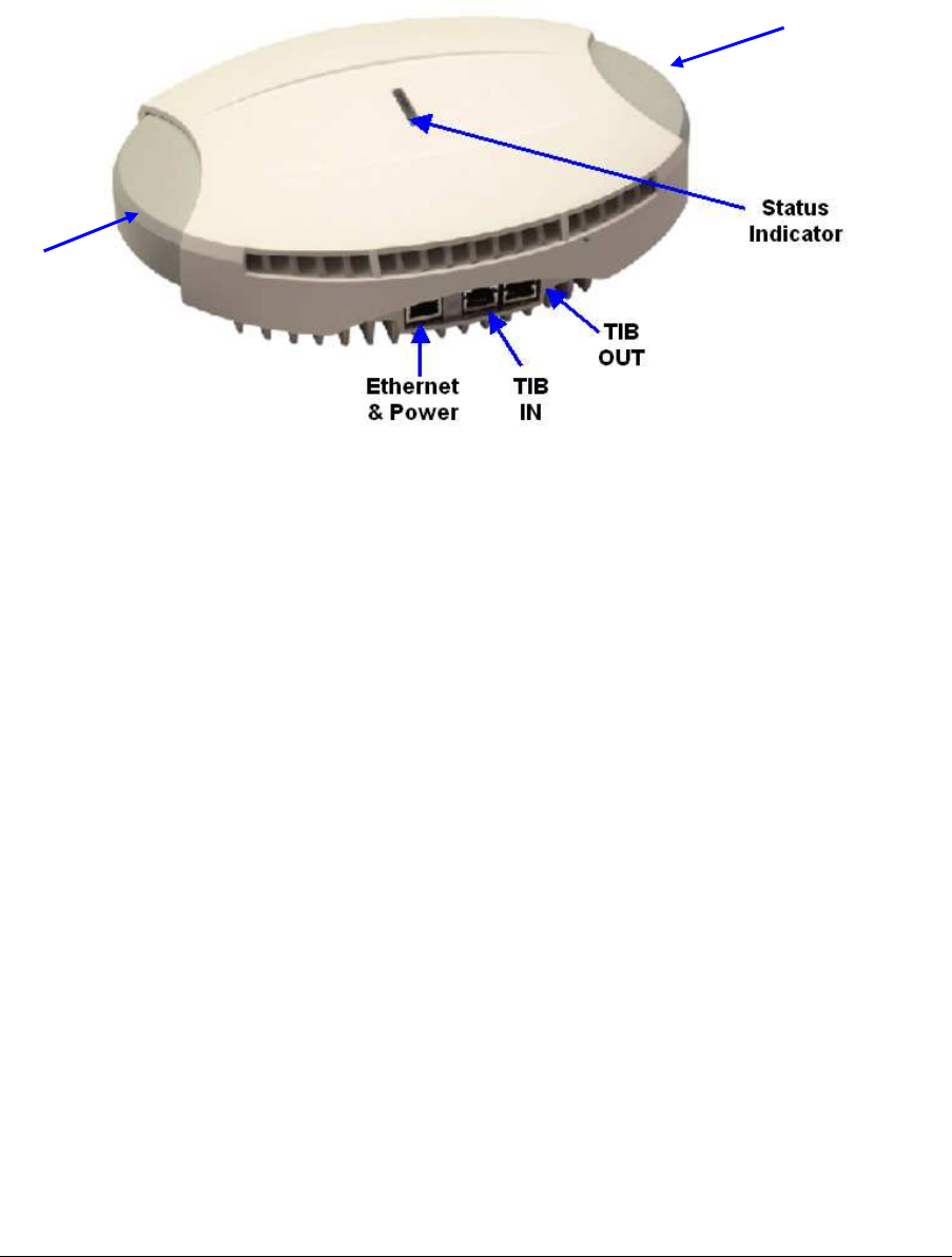
2.5.2 165 Hardware
TX Port
RX Port
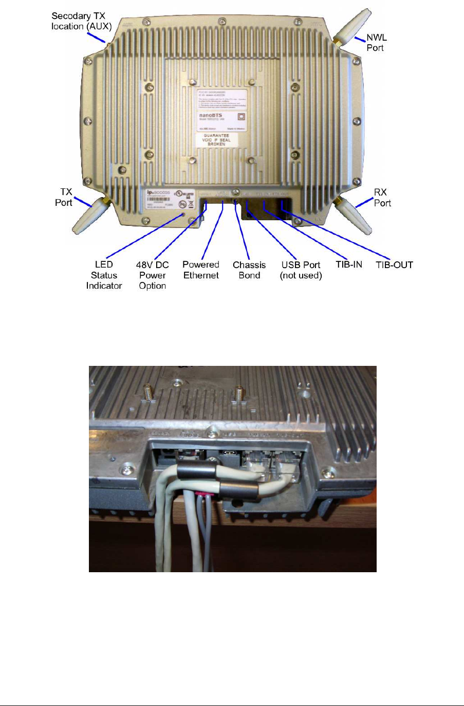
nanoBTS Installation Manual nanoBTS Hardware Installation
© ip.access Ltd Page 6
Figure 7 - 165 nanoBTS connections
For information about using the Secondary TX location (AUX), see section 2.5.8.
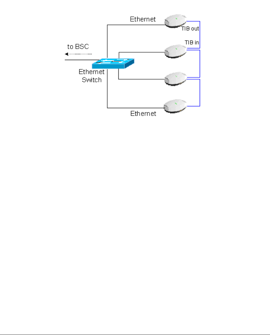
Figure 8 below illustrates the correct cabling of the Ethernet and TIB cables:
Figure 8 - Ethernet and TIB cabling
2.5.3 Ethernet
Each 139/140/178 nanoBTS must be connected to an Ethernet switch or hub via either a
109 ip.access single power inserter or 126 ip.access Powered Ethernet Switch. Refer to
section 5 for details of the power supply connections. The 165 EDGE nanoBTS may use
nanoBTS Installation Manual nanoBTS Hardware Installation
© ip.access Ltd Page 7
either the above power options or a separate 48V DC power supply available from
ip.access.
2.5.4 Timing Interface Bus (TIB) – Multi-TRX only
The Timing Interface Bus (TIB) is used to provide clock and signalling between the
nanoBTS when operating in a Multi-TRX configuration.
The TIB OUT from the Master TRX must be connected to the TIB IN of the slave TRX.
This in turn has its TIB OUT connected to the next TRX in the chain. See Figure 9.
Figure 9 - TIB connections
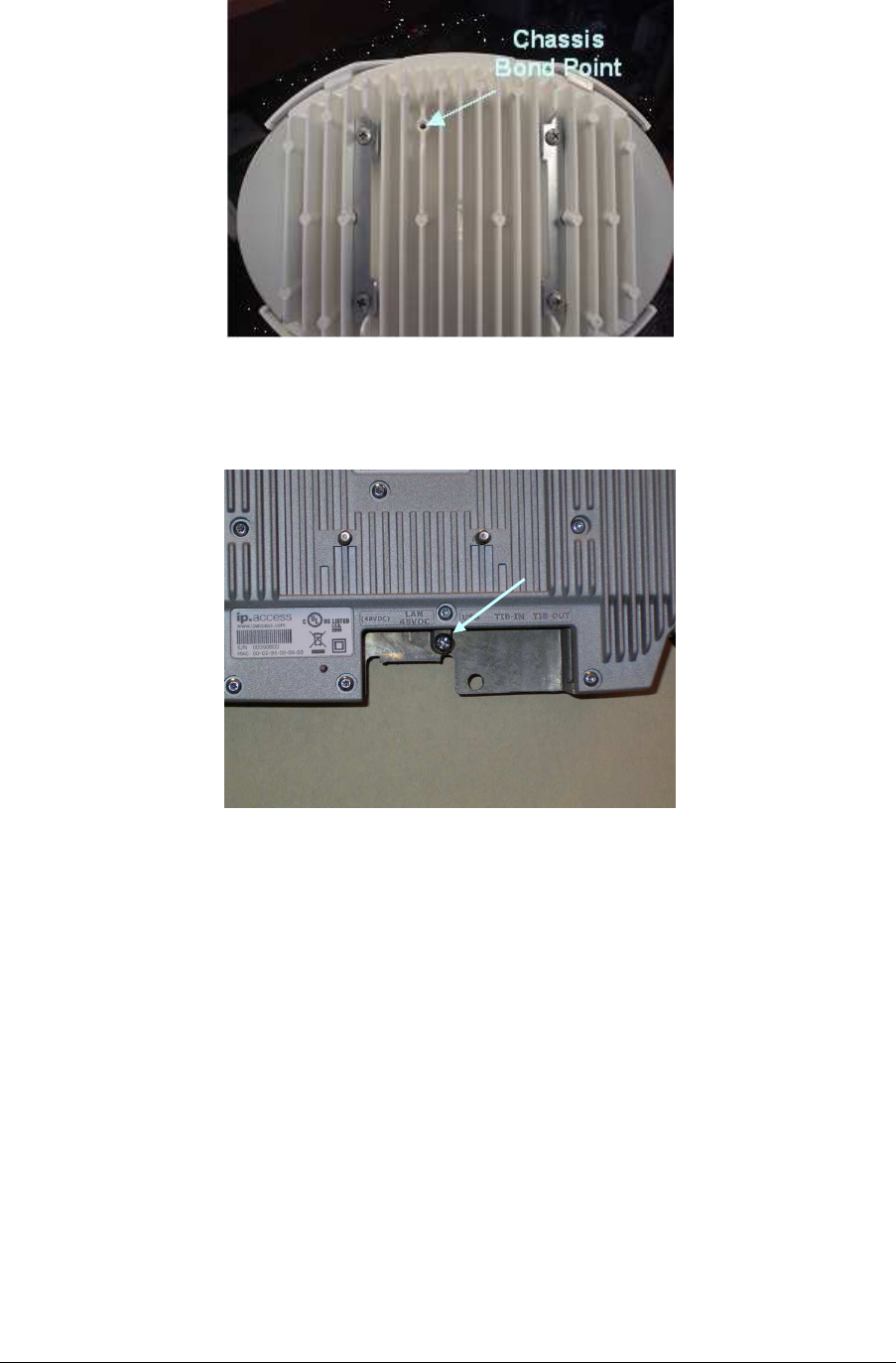
2.5.5 Chassis Bond Strap – Multi-TRX only
When the nanoBTS is operated in a Multi-TRX configuration, each of the nanoBTS must
be connected together using the supplied chassis bond kit.
To fit the chassis bond strap, remove the nanoBTS from the mounting plate.
Using the screw provided, screw the Chassis Bond Strap to the screw on the rear of the
nanoBTS, see Figure 10 or Figure 11.
nanoBTS Installation Manual nanoBTS Hardware Installation
© ip.access Ltd Page 8
Figure 10 - Chassis bond screw location - 139/140 nanoBTS
Connect the other end of the Chassis Bond lead to the next nanoBTS chassis bond point
in the chain.
Figure 11 - Chassis bond screw location - 165 nanoBTS
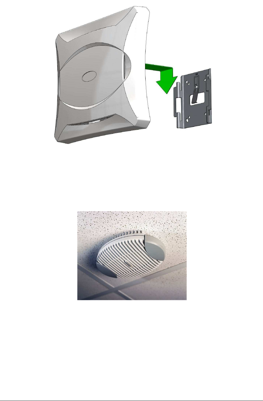
2.5.6 Mounting the nanoBTS
The location of each nanoBTS is shown on the installation floor plan produced at the
network planning stage. For example, it must take into account that all BTSs must be at
least 2m from any mobile equipment. The network wiring must be complete before the
nanoBTS can be installed and commissioned. The nanoBTS should be placed on a wall
(at or above head height) or on a ceiling. Unless explicitly stated otherwise, the following
procedure is common for both 139/140 and 165 hardware variants.
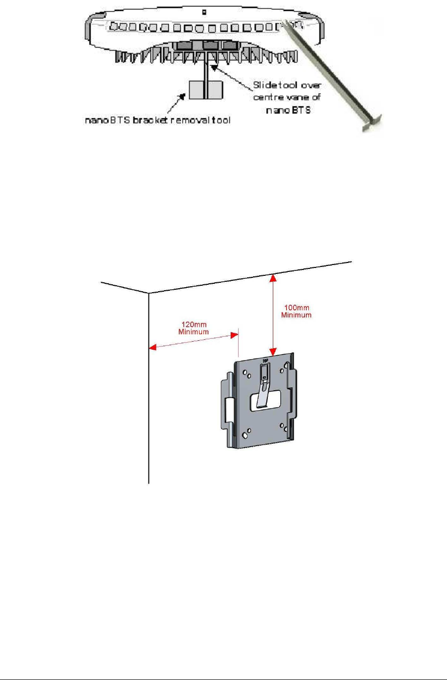
Remove the nanoBTS from the bracket by sliding the removal tool over the central fin
between the bracket and the body of the unit to disengage the locking spring, slide bracket
to separate it from the main body of the unit. The tool may be inserted from the top or
bottom of the nanoBTS.
Chassis
Bond Point
nanoBTS Installation Manual nanoBTS Hardware Installation
© ip.access Ltd Page 9
Figure 12 - nanoBTS bracket removal
Position the bracket on the wall and mark the position of the four screw holes. The top of
the bracket MUST be positioned uppermost. Ensure that the bracket is level and sufficient
clearance is maintained to allow the unit to be located on the bracket (at least 80mm from
the bracket to the top of wall, and 120mm from the side of the bracket to a side wall). See
Figure 13.
Figure 13 - Fixing the wall bracket
Drill the four holes in the positions marked previously and insert wall plugs (if required) and
fix the mounting bracket securely to the wall. The bracket is designed to allow the
nanoBTS unit to be mounted with the connections either at the top or at the bottom of the
unit.
Slide the nanoBTS onto the bracket and ensure that the retaining spring engages into the
indent at the rear of the unit.
nanoBTS Installation Manual nanoBTS Hardware Installation
© ip.access Ltd Page 10
Figure 14 – Mounting the nanoBTS
When fixing to a ceiling or a sloping wall the same fixing process and clearances should be
observed as for fixing to a wall (at least 100mm from the bracket to the top of wall and
120mm from the side of the bracket to a side wall). On a sloping surface the top of the
bracket MUST be uppermost. Once the unit has been attached to the bracket the outer
cover MUST be removed to expose the cooling vanes, as shown in Figure 15.
Figure 15 - Ceiling mounted nanoBTS
2.5.7 Mounting Multi-TRX nanoBTS
When the nanoBTS are to be installed in a Multi-TRX configuration, then each TRX should
be installed in a similar orientation but not closer than 30cm to each other.
A further specific constraint is that the TIB cables must be <1.5m and a 1.5mm
2
Chassis
Bond cable must also be connected between each TRX with a length not exceeding that of
the TIB cable.

nanoBTS Installation Manual nanoBTS Hardware Installation
© ip.access Ltd Page 11
2.5.8 Mounting Multi-TRX 165 nanoBTS
The 165 (EDGE) BTS may be installed in a stacked two-TRX configuration. See section
2.5.10 for details.
The procedure for mounting a stacked two-TRX configuration is as follows:
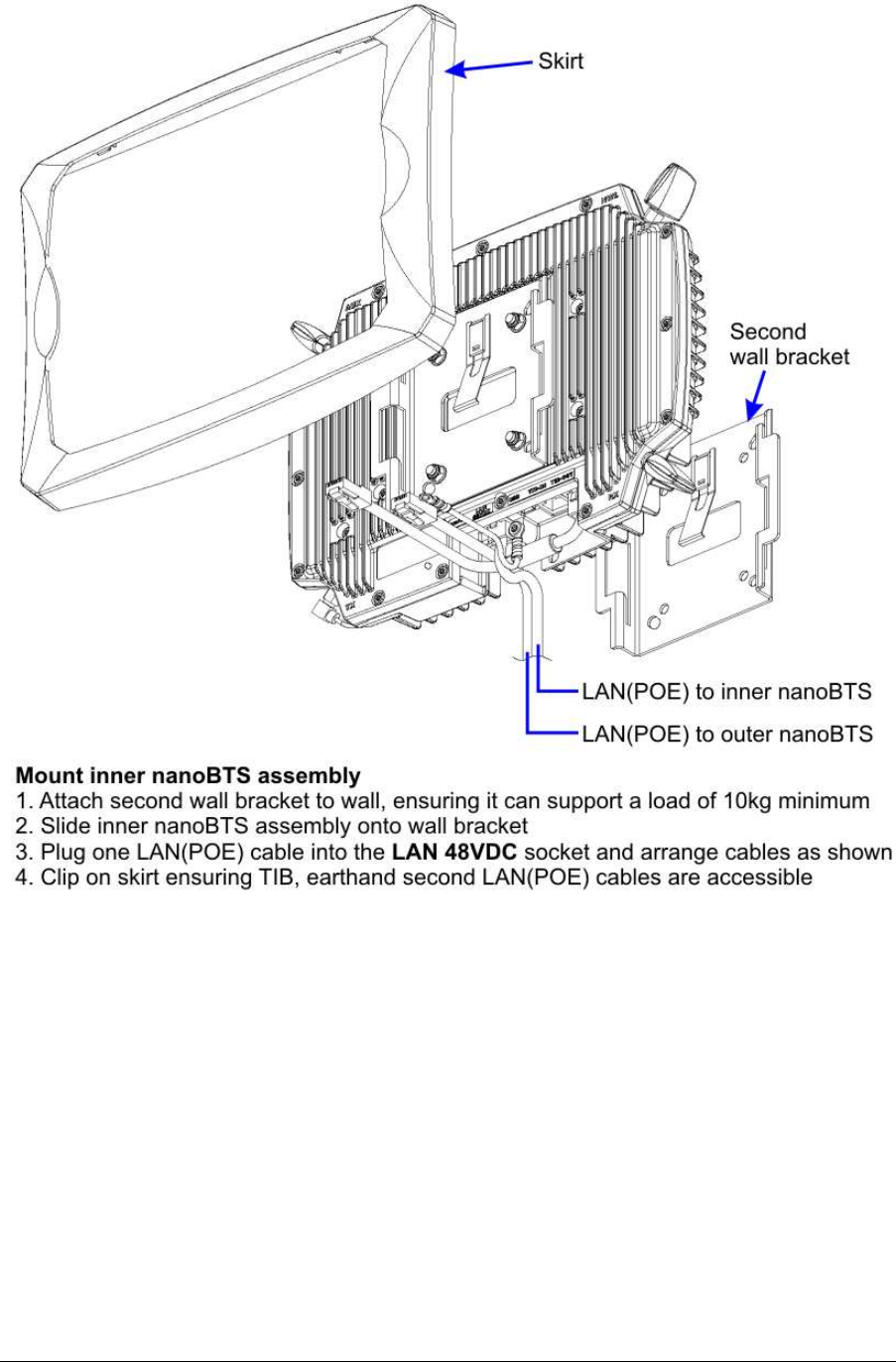
1. Fit the first wall bracket to the wall in the desired position.
2. Remove the plastic cover from the bottom unit.
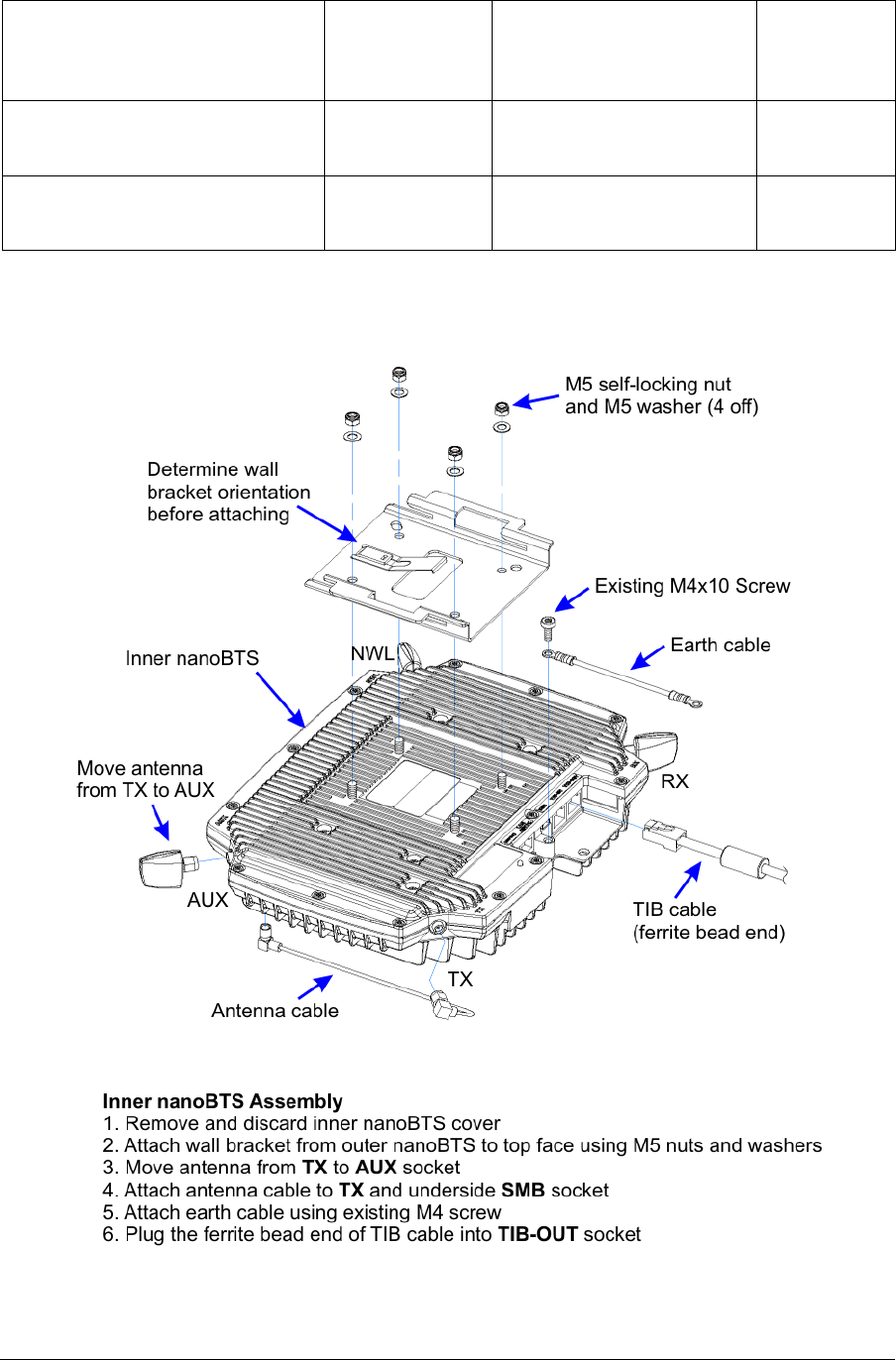
3. Relocate the TX antenna as illustrated in section 2.5.10.
4. Fit the antenna cable (part number 165_072) as illustrated in section 2.5.10.
5. Fit the second wall bracket to the bottom unit as illustrated in section 2.5.10.
6. Mount the bottom unit on the wall.
7. Fit the Ethernet and TIB cables to the bottom unit.
8. Fit the skirt to the bottom unit.
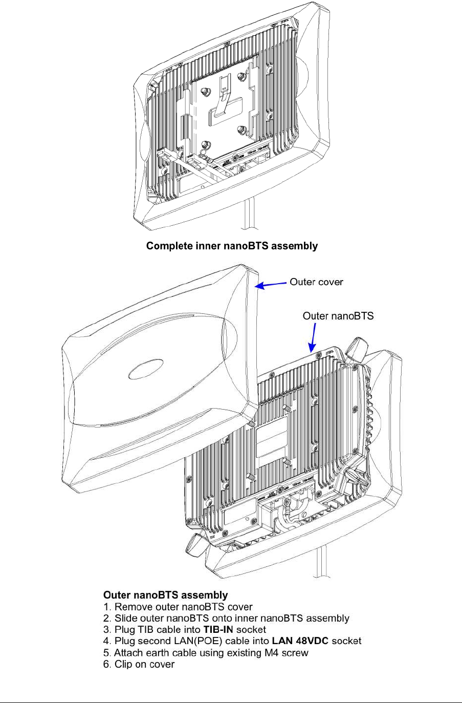
9. Remove the plastic cover from the top unit and attach it to the bottom unit.
10. Attach the Ethernet and TIB cables to the top unit.
11. Replace the plastic cover on the top unit.

nanoBTS Installation Manual nanoBTS Hardware Installation
© ip.access Ltd Page 12
2.5.9 LED Status Indicators
The following table shows the meaning of the state LED under normal and fault conditions.
State Pattern When Precedence
LED_SELF_TEST_FAILURE Red
Steady In boot or application
code when a power on
self-test fails
1 (High)
LED_UNSPECIFIED_FAILURE
Red
Steady On s/w fatal errors 2
LED_NO_ETHERNET Orange
Slow Flash Ethernet disconnected 3
LED_FACTORY_RESET Red
Fast Blink Dongle detected at start
up and the factory
defaults have been
applied
4
LED_NOT_CONFIGURED Alternating
Red/Green
Fast Flash
The unit has not been
configured 5
LED_DOWNLOADING_CODE Orange
Fast Flash Code download
procedure is in progress 6
LED_ESTABLISHING_XML Orange
Slow Blink A management link has
not yet been established
but is needed for the
TRX to become
operational.
Specifically: for a master
a Primary OML or
Secondary OML is not
yet established; for a
slave an IML to its
master or a Secondary
OML is not yet
established.
7
LED_SELF_TEST Orange
Steady From power on until end
of backhaul power on
self-test
8
LED_NWL_TEST Green
Fast Flash OML established, NWL
test in progress 9
nanoBTS Installation Manual nanoBTS Hardware Installation
© ip.access Ltd Page 13
LED_OCXO_CALIBRATION Alternating
Green/Orange
Slow Blink
The unit is in the fast
calibrating state [SYNC] 10
LED_NOT_TRANSMITTING Green
Slow Flash The radio carrier is not
being transmitted 11
LED_OPERATIONAL Green
Steady Default condition if none
of the above apply 12 (Low)
2.5.10 165 Series 2TRX Assembly
nanoBTS Installation Manual nanoBTS Hardware Installation
© ip.access Ltd Page 14
nanoBTS Installation Manual nanoBTS Hardware Installation
© ip.access Ltd Page 15
nanoBTS Installation Manual nanoBTS Hardware Installation
© ip.access Ltd Page 16
2.6 Power Supply Installation
Two power supply modules are available from ip.access, designed for use with the
ip.access nanoBTS product range.
The single output power supply is commonly used for single site installations. The powered
Ethernet switch is generally used at sites where multiple nanoBTS installations exist.
2.6.1 Warnings
Do not connect any device other than a nanoBTS to any RJ45 socket that is
enabled for nanoBTS connection (i.e. 48V DC operation).
Ensure that the connection to the main LAN (Server) is only made to the
UPLINK (i.e. 48V DC operation).
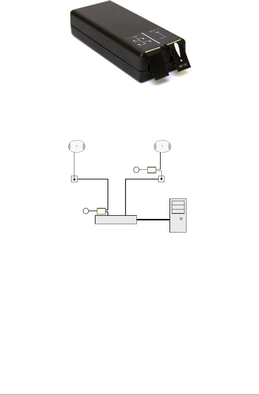
2.7 Single Power Supply Unit Installation
The single power supply unit is supplied as standard with each nanoBTS. The power
supply has two Ethernet connections, one for connection to the main LAN, the other for
connection to the nanoBTS.
nanoBTS Installation Manual nanoBTS Hardware Installation
© ip.access Ltd Page 17
Figure 16 - Single power supply unit
The mains input is provided via a figure 8 mains lead connected to the mains supply of
either connection. Figure 17 shows the network connections for two possible installation
options.
Ethernet Switch
nanoBTS nanoBTS
BSC
RJ45
(48v)
~
~
RJ45
PSU φ
φφ
φ
PSU θ
θθ
θ
θ
θθ
θPSU located at the switch
φ
φφ
φPSU located at nanoBTS
Figure 17 - Locating the PSU
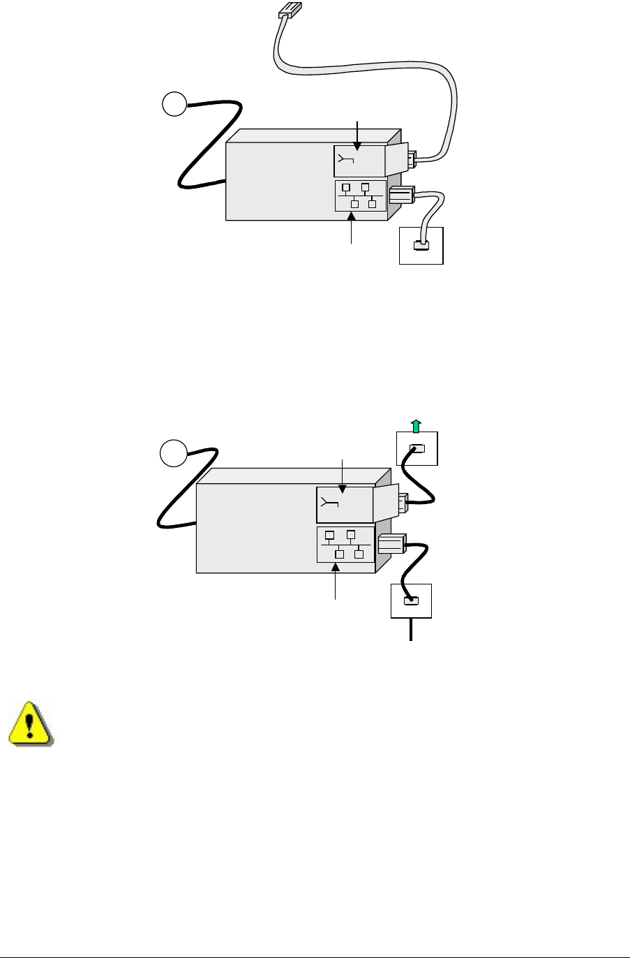
The power supply can be either located locally at the nanoBTS, as shown in Figure 18, or
remotely at the network switch, as long as no other network elements are installed
between the two points, as shown in Figure 19.
nanoBTS Installation Manual nanoBTS Hardware Installation
© ip.access Ltd Page 18
RJ45
Connection to LAN
~
PSU
48Vdc
48Vdc
!
110-230Vac
Connection to nanoBTS
Figure 18 - PSU located at the nanoBTS
~
PSU
48Vdc
48Vdc
!
110-230Vac
RJ45
Connection to LAN
Connection to nanoBTS
Cable to nanoBTS
Figure 19 - PSU installation at the switch
Do not connect any device other than a nanoBTS to any RJ45 socket that is
enabled for nanoBTS connection (i.e. 48Vdc operation).
nanoBTS Installation Manual nanoBTS Hardware Installation
© ip.access Ltd Page 19
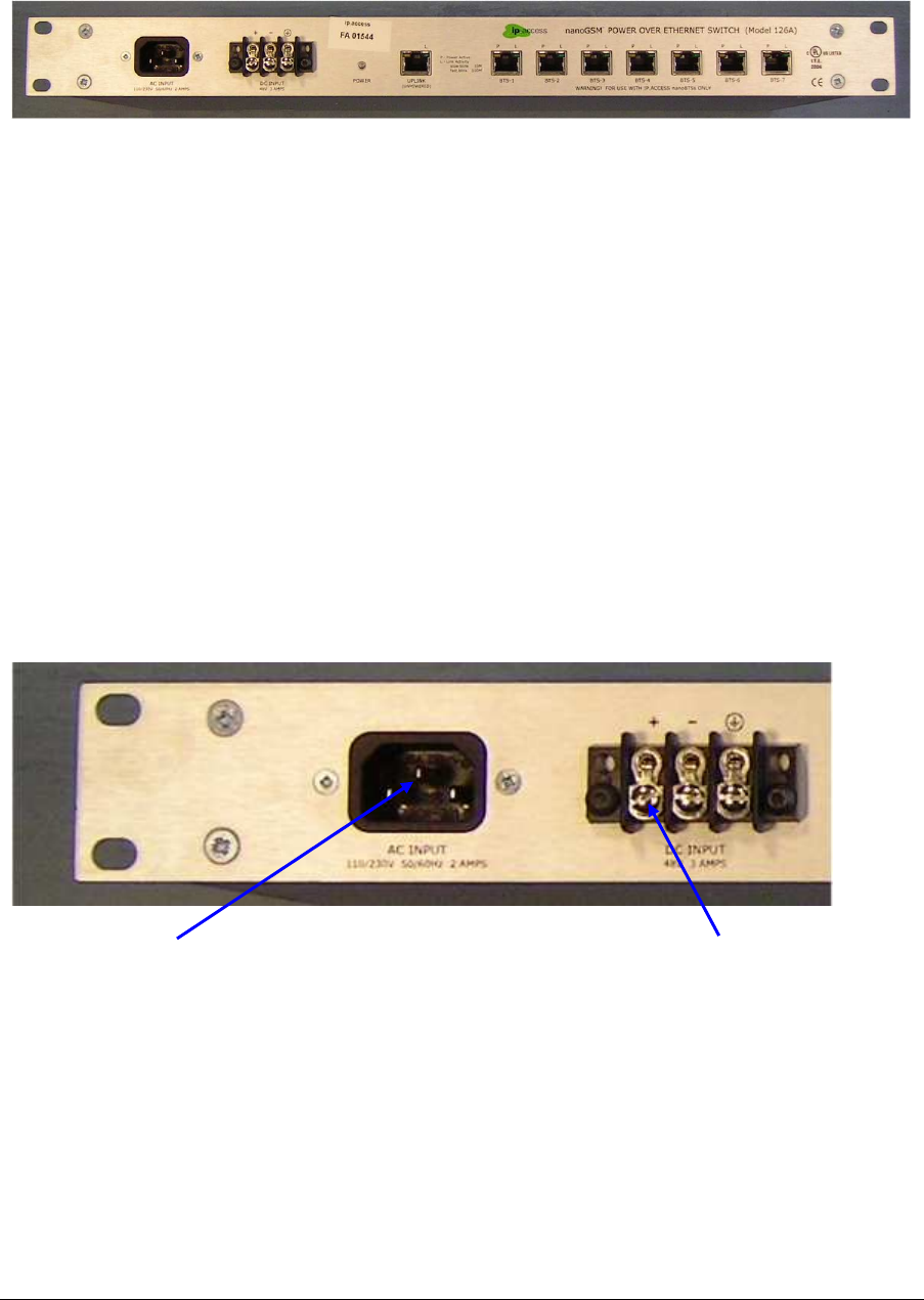
2.7.1 8 Port Powered Ethernet Switch Installation
The 8 port powered Ethernet switch, is a combined power inserter, for use with the
ip.access range of products and a fully functional 10/100 Ethernet switch.
Figure 20 - 8 port powered Ethernet switch
Power to the unit is provided via a 110 – 240 Volt ac mains plug or via a 48 Volt dc plug
and housed in a 1U 19" rack mount case.
2.7.1.1 Mounting The 8 Port Powered Ethernet Switch
The unit is designed to be mounted within a standard 19" rack, and occupies just 1U
height, with all connections accessible from the front panel.
Insert 4 cage nuts in the 19" equipment rack at the height and location that the 8 Port
Powered Ethernet Switch is to be positioned.
Taking care, slide the 8 Port Powered Ethernet Switch into location, holding the switch
steady, then with 4 mounting screws, secure the 8 Port Powered Ethernet Switch into the
rack.
2.7.1.2 Connecting The 8 Port Powered Ethernet Switch
Connect only one of the required power input connectors to the 8 Port Powered Ethernet
Switch, either mains 110/240V AC or 48V DC.
Figure 21 - Supply connections
Once the 8 Port Powered Ethernet Switch is mounted and the mains AC / DC supply is
connected, the main network can be connected, as shown in Figure 22. When powered
from the mains AC, ensure the unit is earthed via the IEC power cord. When powered from
a 48V DC supply, ensure the unit is earthed via a cable to the screw terminal.
Mains 110-240V AC 48V DC
nanoBTS Installation Manual nanoBTS Hardware Installation
© ip.access Ltd Page 20
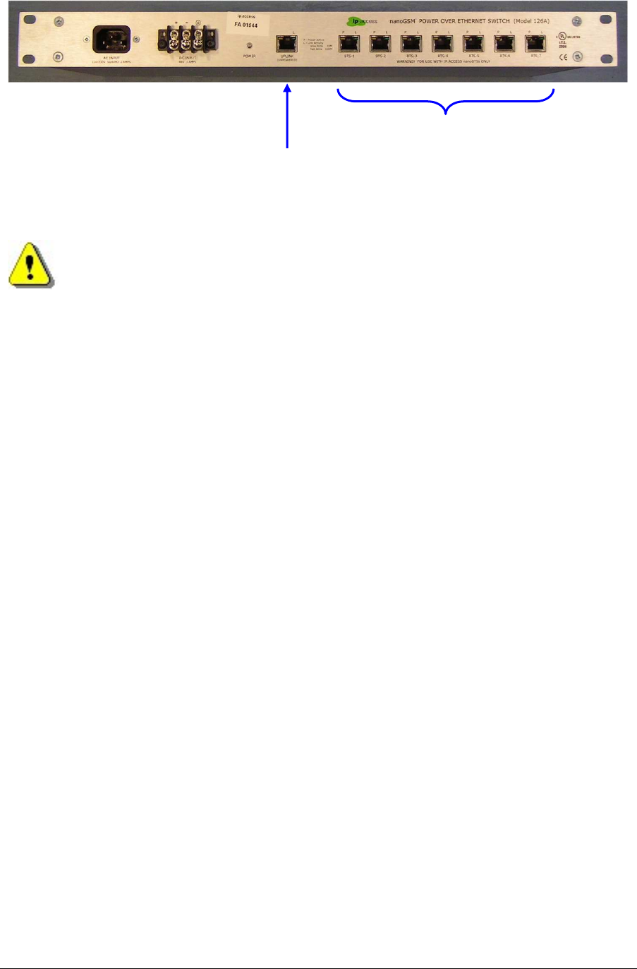
Figure 22 - Ethernet connections
Ensure that the connection to the main LAN (Server) is only made to the
UPLINK (unpowered).
Connect each nanoBTS to one of the powered Ethernet outputs, ensuring that the
connection is made only to an ip.access nanoBTS.
Uplink
connection
Downlink
connections

nanoBTS Installation Manual Getting Started with BTS Installer
© ip.access Ltd Page 21
3 GETTING STARTED WITH BTS INSTALLER
After the nanoBTS hardware has been installed on site, it must be commissioned into the
network. This is done by configuring the nanoBTS with BTS Installer. This chapter
provides an overview of BTS Installer and installation instructions. Refer to the following
chapter for instructions on commissioning a nanoBTS with BTS Installer. Readers familiar
with BTS Installer may wish to skip this chapter.
Note: While it is possible to pre-configure a nanoBTS before it is installed on site, this
manual assumes that a nanoBTS will be configured after site installation.
3.1 Configuration Phases
Configuration of a nanoBTS takes place in a number of phases. In automatic mode (see
section 3.2.1) all enabled phases are run automatically one after another in a fixed order.
In manual mode the user chooses which phase to run, one at a time, and can also perform
other actions which are not equivalent to automatic configuration phases.
The configuration phases are, in the order in which they are run in automatic mode:
1. Setting the nanoBTS’ IP configuration using the built-in DHCP server.
2. Setting the nanoBTS’ Unit ID.
3. Setting the nanoBTS’ non-volatile attributes.
4. Downloading a file to the nanoBTS.
Each phase can be enabled or disabled separately for each nanoBTS. The download file
can download any one of: software; a certificate; a certificate revocation list, but can only
download one file at a time.
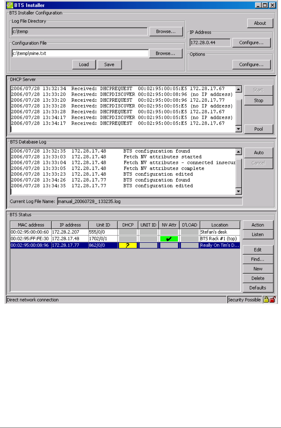
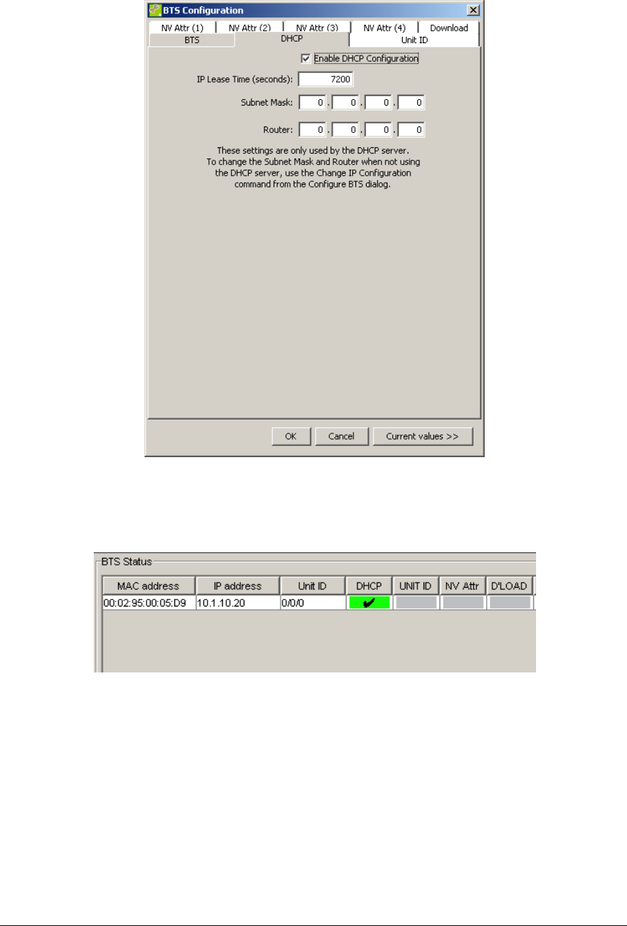
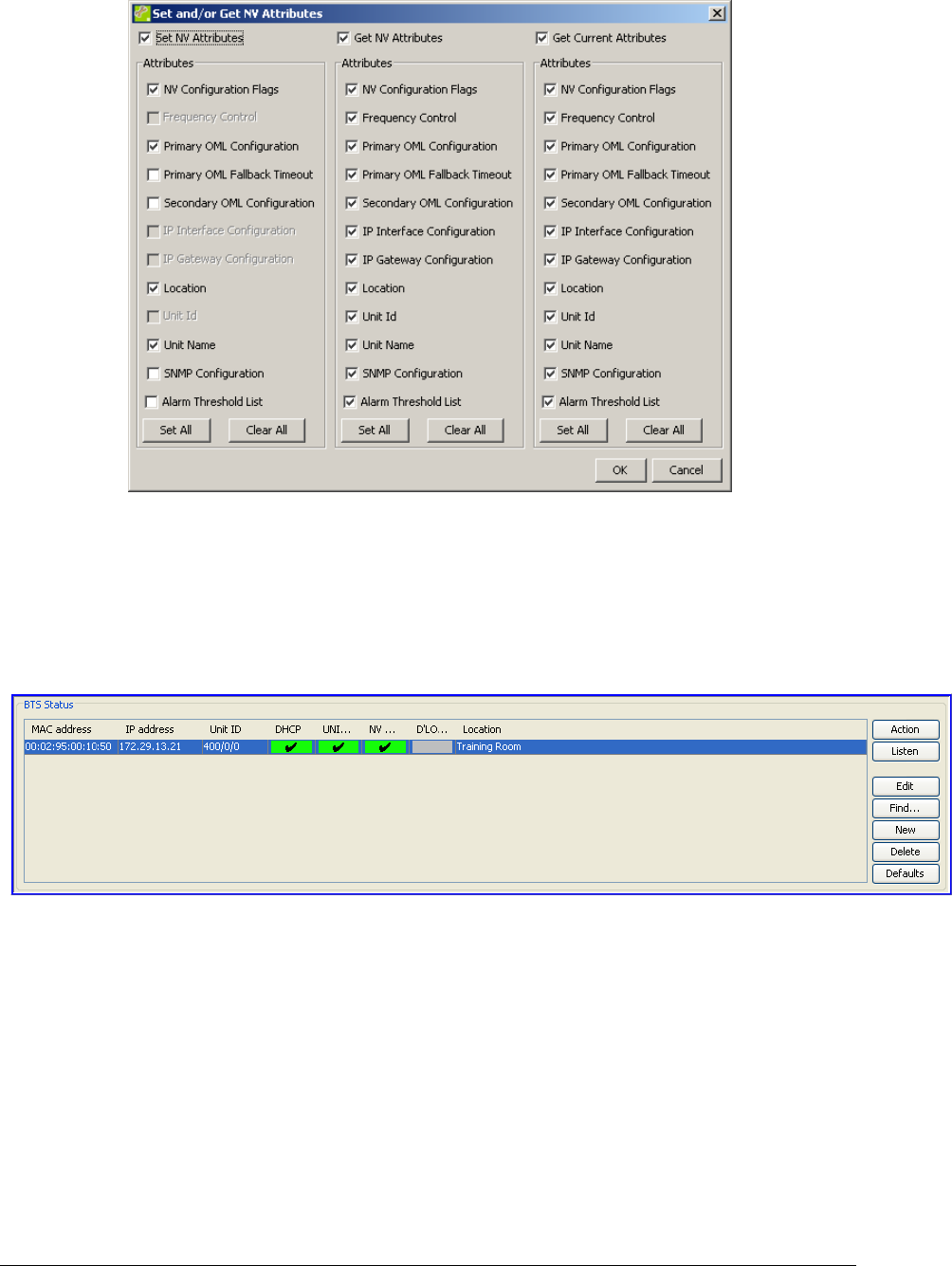
The BTS Status section of the user interface gives a quick reference to which phases are
enabled for which nanoBTSs: this is indicated by the colour code in the columns headed
respectively DHCP, UNIT Id, NV Attr, D’LOAD. Grey indicates that this phase is disabled
for this nanoBTS, any other colour indicates that this phase is enabled for this nanoBTS.
Status colours other than grey are accompanied either by explanatory text, or by a symbol
(Grey = no symbol, Red = cross, Yellow = question mark, Red = tick).
3.2 Modes of Operation
BTS Installer has a variety of different modes of operation, to suit different circumstances
and requirements.
3.2.1 Manual and Automatic Operation
BTS Installer has an automatic mode of operation, in which it will apply all enabled phases
of configuration to all known nanoBTSs in parallel, and when it has finished it will produce
a summary in the log window and log file and will display in the BTS Status window which
phases of configuration for which nanoBTSs have succeeded and which have failed.
This automatic mode of operation is initiated by pressing the Auto button in the BTS
Database Log section of the user interface.

nanoBTS Installation Manual Getting Started with BTS Installer
© ip.access Ltd Page 22
BTS Installer also has a manual mode of operation, in which the user performs just one
operation at a time on just one nanoBTS at a time, and has immediate feedback as to the
success or failure of the operation.
The various manual operations are available from pressing the Action button in the BTS
Status section of the user interface.
Some example scenarios are:
• A number of operating nanoBTSs are to have their software upgraded. Automatic
mode is used to download the new version of software to all of them at once.
• A particular nanoBTS is not operating correctly. Manual mode is used to investigate
its configuration and diagnose and fix the problem.
3.2.2 Unknown BTS Mode
Normally the BTS Database contains entries for specific nanoBTSs. In particular the
DHCP server will only normally only supply an IP configuration to a nanoBTS whose MAC
address matches that explicitly specified in the BTS Database entry.
There is a special “Unknown BTS” mode of operation in which the BTS Database contains
just one special entry. This special entry acts as if it had a wildcard MAC address, and the
DHCP server will recognise any nanoBTS that asks for an IP configuration.
IN THIS MODE THERE IS NOTHING IN BTS Installer TO STOP THE
CONFIGURATION OF ANY nanoBTS THAT IS CONNECTED TO THE
NETWORK FROM BEING CHANGED.
This special mode of operation is designed to be used when only one nanoBTS at a time is
connected to the computer running BTS Installer, usually on a tiny private network,
perhaps just a crossover cable. It bypasses the normal safeguards that BTS Installer uses
to ensure that it makes configuration changes only to BTSs that are identified as those that
the user has specified.
There is no way to create this special BTS Database entry from the graphical user
interface; it must be loaded from a configuration file. There is no particular indication to the
user that BTS Installer is in Unknown BTS Mode, except that the Find and New buttons in
the BTS Status section of the user interface are disabled.
3.2.3 Proxy and Direct Operation
There are various network configurations in which BTS Installer may be used, and the
general design of the IP network configuration is outside the scope of this document.
In some network configurations BTS Installer is on the same network as the nanoBTSs, in
that there is an IP route from BTS Installer to the nanoBTSs. In such configurations BTS
Installer can communicate directly with the nanoBTSs in direct connection mode.
There are two different types of direct connection that BTS Installer can make to a
nanoBTS: a normal TCP connection or a secure SSL connection.
In other network configurations BTS Installer and the nanoBTSs are on different networks,
and there is no IP routing between the two. Typically in this scenario the BSC will be
multihomed, and will have an interface to each network but will not route IP packets
between the two networks. An optional system component, the BTS Installer Proxy, can be
installed as part of the BSC, and will forward requests from BTS Installer to the nanoBTSs

nanoBTS Installation Manual Getting Started with BTS Installer
© ip.access Ltd Page 23
and return the replies. In such configurations BTS Installer communicates with the
nanoBTSs in proxy mode.
There are two different types of proxy that might be present on a BSC: a Primary OML
Proxy and a Secondary OML Proxy. Which can be used depends on the network
configuration.
Direct connection or proxy mode is indicated to the user in the status bar at the bottom of
the user interface. A later section explains how to start BTS Installer in proxy mode, and
lists the limitations of BTS Installer whilst in proxy mode.
3.3 The Configuration File
BTS Installer can be given the information it needs in the following ways:
• in a configuration file
• via the graphical user interface
• via some combination of a configuration file and the graphical user interface
The configuration file is a text file which can be created with any text editor and which
contains definitions for:
• default values for BTS attributes
• the nanoBTSs to be operated on
• attributes to be set for the BTSs
• the DHCP server’s IP address pool
It is not necessary to create a configuration file for most uses of BTS Installer, as almost all
necessary information can be entered via the graphical user interface. The only exception
is that a BTS Database entry for the “Unknown BTS” cannot be entered via the GUI and
can only be entered via the configuration file.
At any point it is possible to save the current state of the BTS Database and IP address
pool to a configuration file; this can be done even if no configuration file has been loaded
and all data has been entered via the GUI. This allows you to do the following:
• entering configuration information via the GUI
• saving the configuration information to a new configuration file
• loading the configuration file in a later run of BTS Installer
In other words, you can use BTS Installer itself to create a configuration file for later use,
instead of using a text editor.
See 'Configuration File Reference' in [OPM_300] for details of the syntax of the
configuration file.
3.4 Installing BTS Installer
This section contains information about installing BTS Installer, preparing it for use, and
performing an operation on a nanoBTS.
BTS Installer is a Java application. It requires that the Sun J2SE Java Runtime
Environment be installed: version 1.5 is required (there is no particular requirement as to
nanoBTS Installation Manual Getting Started with BTS Installer
© ip.access Ltd Page 24
which subversion of 1.5 is used). The J2SE Java Runtime Environment is available, with
installation instructions, from Sun’s Java web-site (http://www.java.sun.com).
3.4.1 Microsoft Windows
3.4.1.1 Pre-Installation Requirements
• Local craft terminal for the installation running Windows 2000 SP2 or Windows XP
SP2
• CD-ROM drive or Internet connection
• Java run time environment version 1.5.0_07 or later
3.4.1.2 Installing the BTS Installer Package
The estimated installation time for the product is 5 minutes.
1. Login to the PC ensuring that you have Administrator privileges.
2. Using Windows Explorer, browse to the directory, either on the CD-ROM or
network drive where the BTS Installer application is located.
3. Double click on the Icon for BTS Installer:
Note: For actual revision levels of each package, please refer to the System
Release Note.
4. Follow the on-screen instructions to complete the installation.
If it is desired to use BTS Installer to make secure (SSL) connections to nanoBTSs then
perform the following additional steps:
5. Install the Aladdin eToken run time environment.
Aladin e-Token RTE requires that the computer is running Windows 2000 SP2 or
Windows XP SP2.
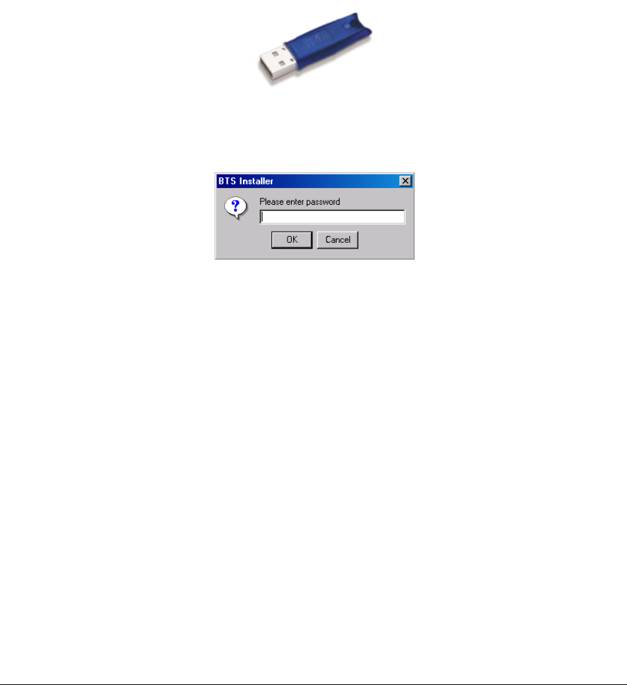
6. Plug the eToken (a hardware device which contains a certificate and private key
for BTS Installer) into a USB port.
3.4.2 Other Platforms
Details of installing BTS Installer on platforms other than Microsoft Windows are beyond
the scope of this document. However in most cases copying the file BtsInstaller.jar to a
suitable directory will be adequate. On platforms other than Windows there is no support
for making SSL connections to the nanoBTS.
3.5 Starting BTS Installer
3.5.1 From Config Manager
BTS Installer can be started from Config Manager, in which case it will be pre-populated
with some nanoBTSs selected in Config Manager and will operate in proxy mode. See
'Starting BTS Installer from Config Manager' in [OPM_300] for details.

nanoBTS Installation Manual Getting Started with BTS Installer
© ip.access Ltd Page 25
3.5.2 Microsoft Windows
BTS Installer can be started by double clicking the desktop item or by selecting the menu
entry in the normal way.
3.5.3 Other Platforms
Details of starting BTS Installer on platforms other than Microsoft Windows are beyond the
scope of this document. However on platforms with a command line interface a command
like the following is likely to be useful:
java -jar BtsInstaller.jar
3.5.4 Command Line Arguments
On all platforms, additional command line arguments can be used to specify that BTS
Installer should run in proxy mode, and/or to specify the IP addresses and optionally Unit
IDs of some nanoBTSs for which BTS Installer should create BTS Database entries. See
'Command Line Parameters' in [OPM_300] for details of the command line arguments.
Depending on the platform, it will be possible to set up a shortcut or a script to run BTS
Installer with any desired set of command line arguments.
3.5.5 Entering the Password
When BTS Installer starts, if an eToken containing a certificate and private key is found it
will prompt the user for the password for the eToken. The password should be entered if it
is desired to make secure (SSL) connections to nanoBTSs; if only insecure connections
are wanted then the password request may be cancelled. See section 4.5 for further
details.
3.6 Setting Up BTS Installer
The BTS Installer Configuration section of the user interface contains some settings that
tell BTS Installer how it is to operate. Until some of these settings have been made most of
the buttons on the user interface will be disabled and most of BTS Installer’s functionality
will be unavailable.
nanoBTS Installation Manual Getting Started with BTS Installer
© ip.access Ltd Page 26
Once these settings have been made they are remembered and will not normally need to
be made again on later runs of BTS Installer on the same computer.
The items that can be set up are:
• Log file directory – this must be set up, but it can alternatively be done as a by-
product of choosing a configuration file
• IP Address – this does not need setting if you are not going to use BTS Installer’s
built-in DHCP server, but if you are going to use the DHCP server then this must be
set up
• Configuration file – this need not be set up unless and until you wish to use a
configuration file

nanoBTS Installation Manual Getting Started with BTS Installer
© ip.access Ltd Page 27
• Options – these usually do not need to be set up as the default values are usually
adequate.
3.6.1 Creating a BTS Database Entry
BTS Installer will not operate on any nanoBTS that it doesn’t know about; in order to do
anything to a nanoBTS it must have a BTS Database entry for that nanoBTS (see section
4.1).
A BTS Database entry can be created by any of the following methods as desired:
• creating a new blank BTS Database entry
• finding a nanoBTS on the local area network
• loading a configuration file
3.6.2 Assigning an IP Address
For most operations (other than when operating via a Primary OML Proxy) the nanoBTS
must have an IP address assigned, and BTS Installer must know the IP address.
If the nanoBTS on which you wish to operate already has an IP address:
• Ensure that the BTS Database entry for that nanoBTS has the correct IP address; if
not use the Edit button to fill in the IP address on the BTS tab of the BTS
Configuration dialog box.
If the nanoBTS on which you wish to operate does not already have an IP address then
you may use BTS Installer’s built-in DHCP server to assign one:
1. Consult the network administrator for the network on which the nanoBTS is
installed and ask for an IP address that can be used for the nanoBTS.
2. Use the Edit button to fill in this IP address on the BTS tab of the BTS
Configuration dialog box.
3. Go to the DHCP tab on the same dialog box, (and if not already done) tick the
Enable DHCP Configuration check box, and enter the correct Subnet Mask (and
Router address, if needed).
4. Ensure that the DHCP server is running.
5. Wait until the DHCP server assigns the address to the nanoBTS.
For more information about editing the nanoBTS’ attributes using the BTS Configuration
dialog box see chapter 4. For more information about the DHCP server, particularly for
conditions that must be satisfied before it will work and assign an IP address to a
nanoBTS, see chapter 4.
3.6.3 Setting Desired nanoBTS Attributes
For many, but not all, operations it is necessary to specify some attributes that you wish to
be configured on the nanoBTS.
Use the Edit button to pop up the BTS Configuration dialog box on which desired attributes
may be entered. See chapter 4 for details of the BTS Configuration dialog box.

nanoBTS Installation Manual Getting Started with BTS Installer
© ip.access Ltd Page 28
3.6.4 Perform Desired Operations
At this point any desired operation may be performed on the nanoBTS:
• automatic configuration – use the Auto button
• manual configuration – use the Action button
• network listen functions – use the Listen button.
nanoBTS Installation Manual Commission a nanoBTS
© ip.access Ltd Page 29
4 COMMISSION A NANOBTS
4.1 Configure the nanoBTS
The process for manually configuring the nanoBTS is as follows:
4.1.1 Set the IP Configuration
1. Power up the nanoBTS. This will take approximately 1 minute. The Status
Indicator on the nanoBTS will flash green and red. This indicates that the Unit ID
has not been set (when the nanoBTS has been fully configured the Status
Indicator will slow blink orange).
2. Open BTS Installer.
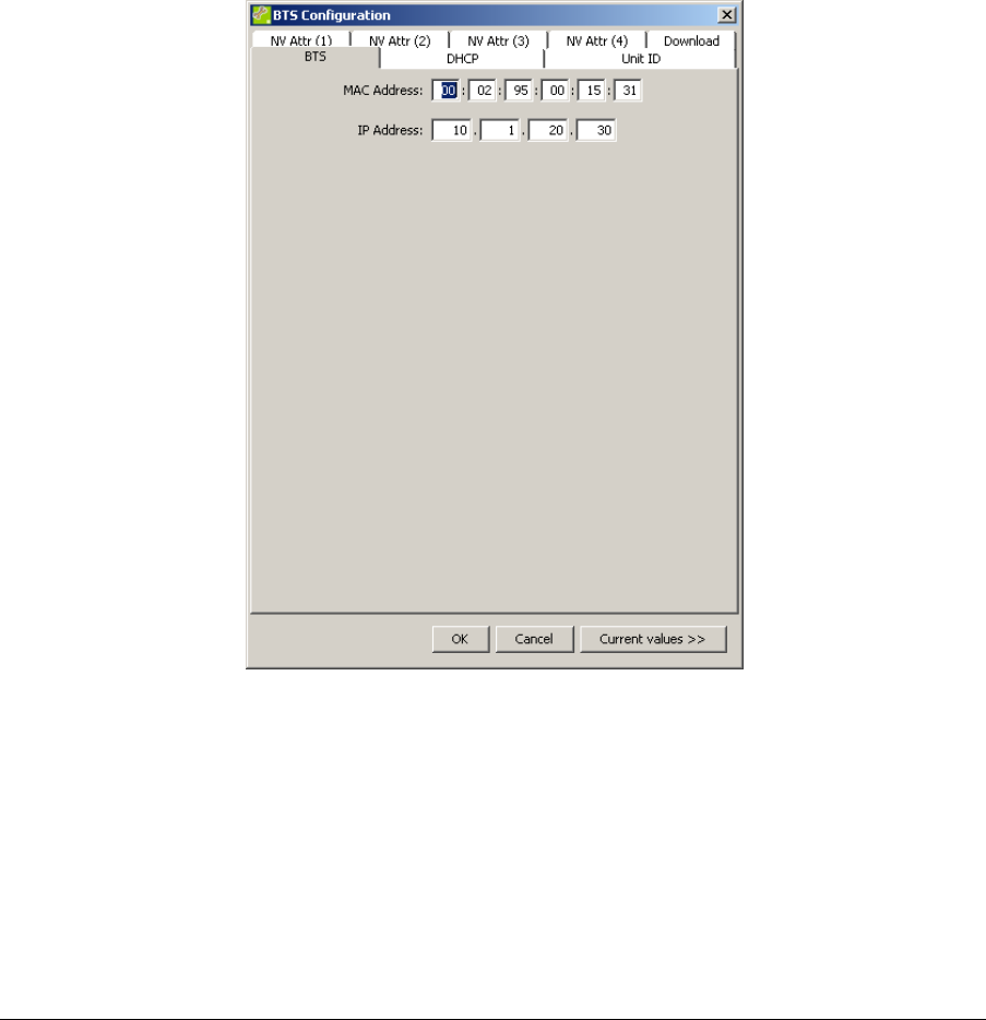
3. In the BTS Status section, click New to add the new nanoBTS to the BTS
database. The BTS Configuration dialog is displayed.
4. On the BTS tab, enter the MAC Address of the new nanoBTS.
5. On the BTS tab, enter the IP Address of the new nanoBTS.
nanoBTS Installation Manual Commission a nanoBTS
© ip.access Ltd Page 30
6. On the DHCP tab, select the Enable DHCP Configuration check box.
7. On the DHCP tab, enter the Subnet Mask and IP Address of the gateway router if
required.
8. Click OK. The DHCP field in the BTS Status section should turn green. If not,
ensure that the DHCP server is running.
nanoBTS Installation Manual Commission a nanoBTS
© ip.access Ltd Page 31
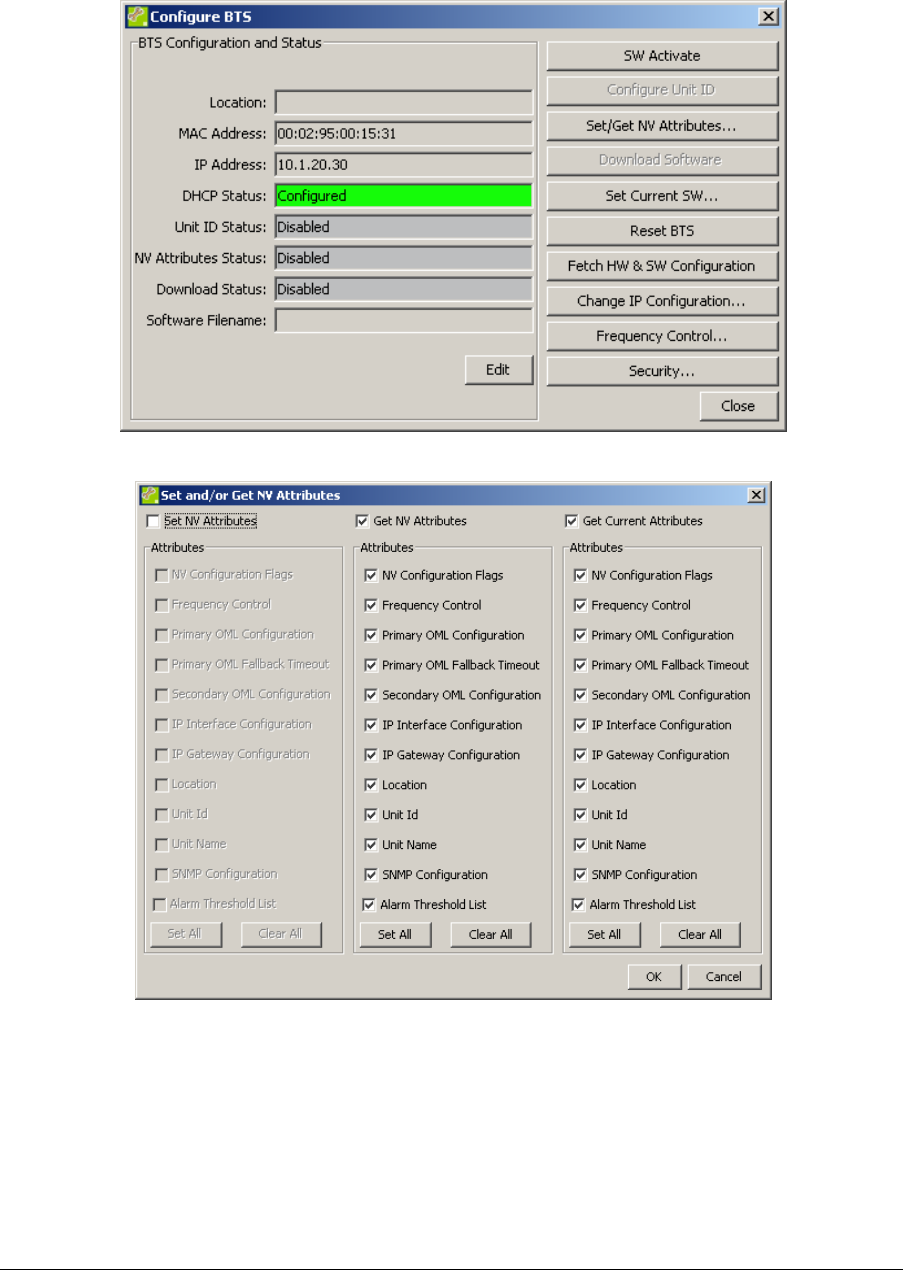
4.1.2 Set the Non-Volatile Attributes
1. Ensure that the new nanoBTS is selected in the BTS Status section, and then
click Action. The Configure BTS dialog is displayed.
2. Click Set/Get NV Attributes.
3. In the Set and/or Get NV Attributes dialog, select the required attributes. By
default all attributes are selected.
4. Click OK. A progress dialog is displayed, then the BTS Configuration dialog is
displayed.
nanoBTS Installation Manual Commission a nanoBTS
© ip.access Ltd Page 32
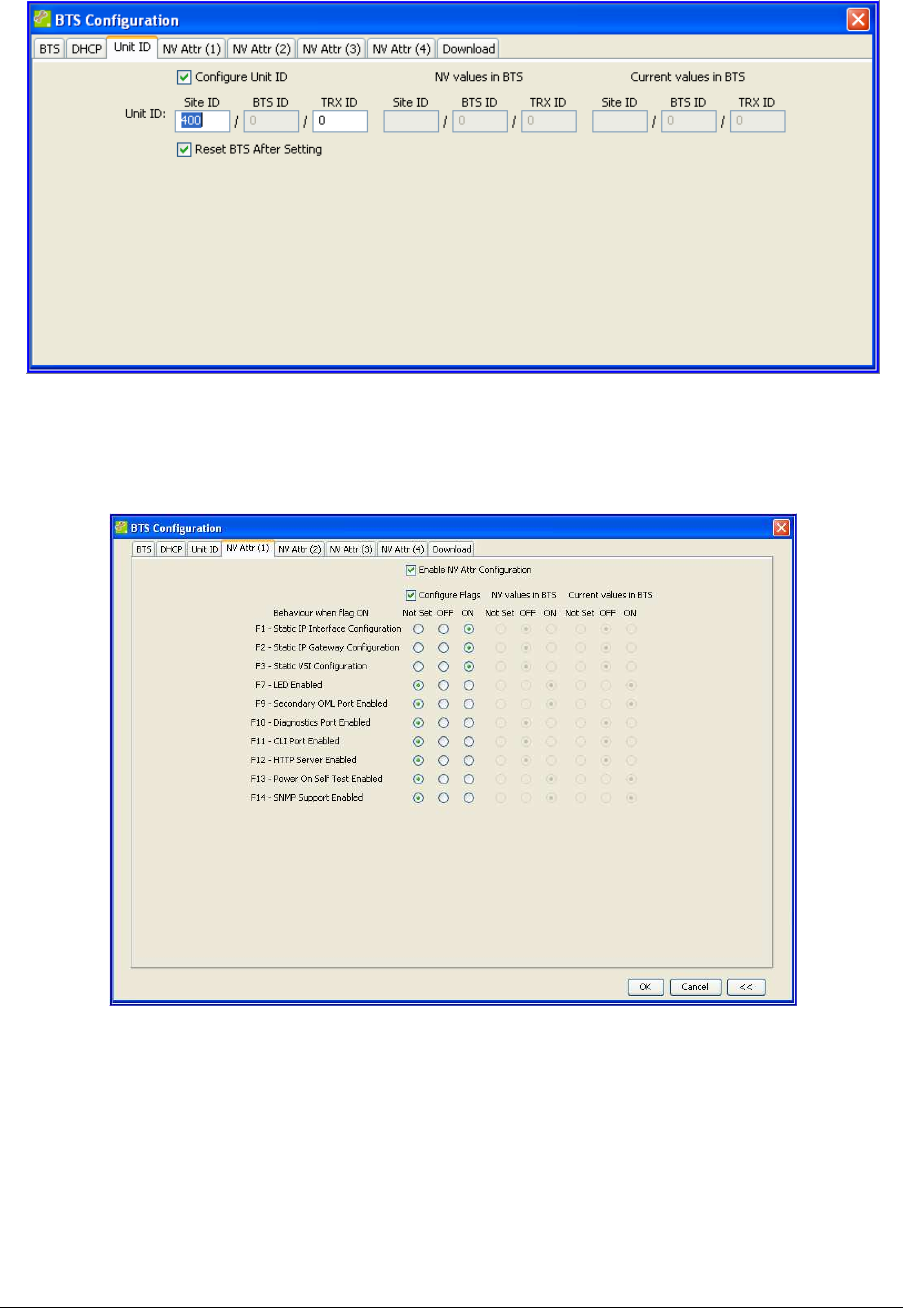
5. On the Unit ID tab, enter a unique Site ID. A slave TRX will have the same Site
ID as the master TRX.
6. On the Unit ID tab, enter a TRX ID. For a master TRX, TRX ID is 0. For a slave
TRX, TRX ID is 1, 2 or 3.
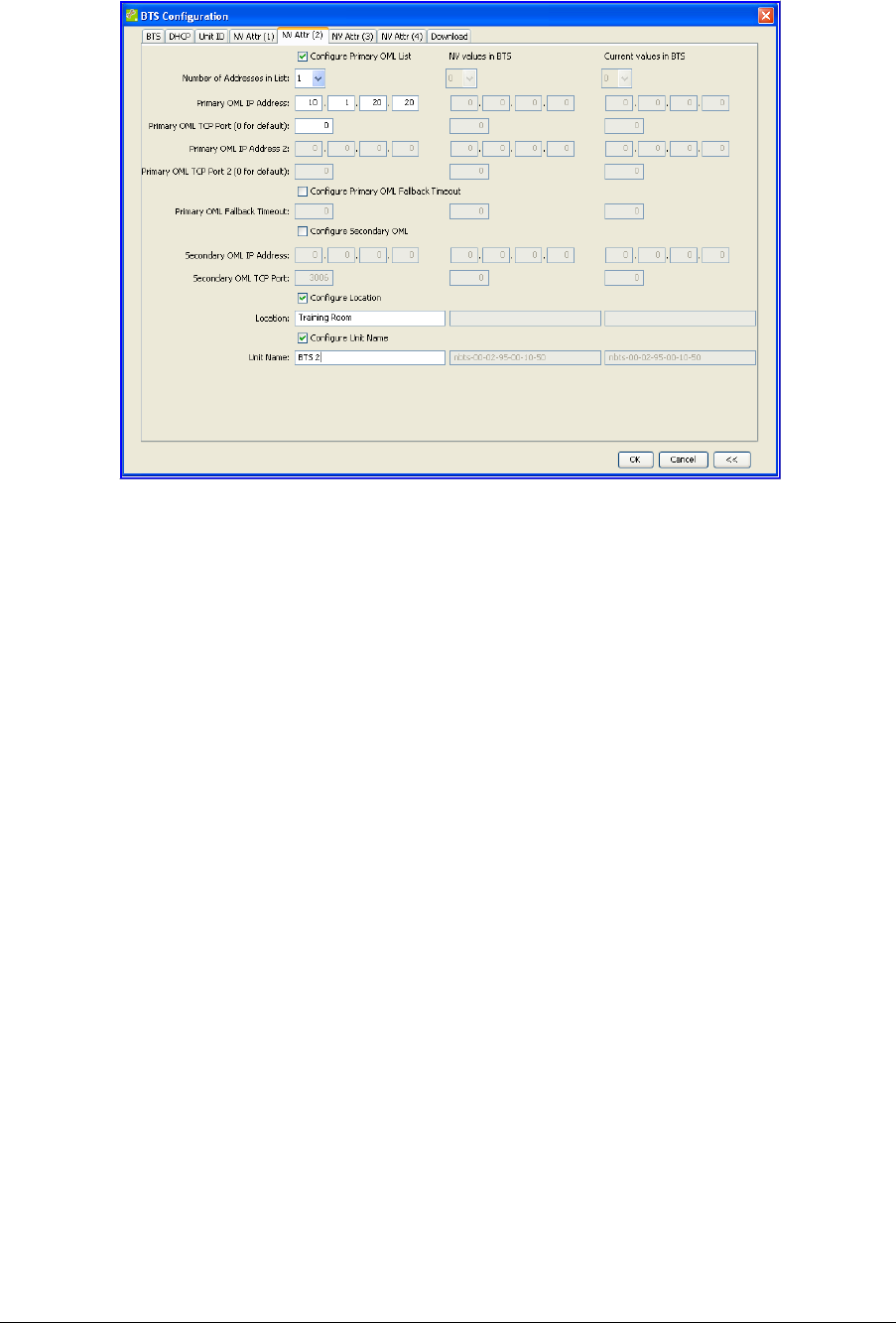
7. On the NV Attr (1) tab, select the Enable NV Attr Configuration check
box.
8. To configure a static IP address, select the Configure Flags check box and
set F1, F2 and F3 to ON. To configure a dynamic IP address, do not make these
settings.
Note: Changes made on the NV Attr (1) tab will not be applied to the BTS until it
has been reset.
nanoBTS Installation Manual Commission a nanoBTS
© ip.access Ltd Page 33
9. On the NV Attr (2) tab, select the Configure Primary OML List check box.
10. From the Number of Addresses in List drop-down list, select the number
of BSCs. Typically this will be 1. If there is a second BSC configured for
redundancy, select 2.
11. Enter the Primary OML IP Address. This is the IP address of the BSC.
12. If there is a second BSC configured for redundancy, enter the Primary OML IP
Address 2.
13. Select the Configure Location check box.
14. Enter appropriate descriptive text in the Location field.
15. Select the Configure Unit Name check box.
16. Enter appropriate descriptive text in the Unit Name field.
Note: Changes made on the NV Attr (2) tab will be applied to the BTS without a
reset.
17. Click OK. In the BTS Status section, the Unit ID field should be yellow, and the
NV Attributes field should be red.
nanoBTS Installation Manual Commission a nanoBTS
© ip.access Ltd Page 34
18. Click Set/Get NV Attributes.
19. In the Set and/or Get NV Attributes dialog, ensure that the Set NV Attributes
check box is selected.
20. Ensure that the check boxes are selected for the required configuration settings.
21. Click OK.
22. In the Configure BTS dialog, click Configure Unit ID. The DHCP, Unit ID and NV
Attributes fields in the BTS Status section should all be green.
nanoBTS Installation Manual Commission a nanoBTS
© ip.access Ltd Page 35
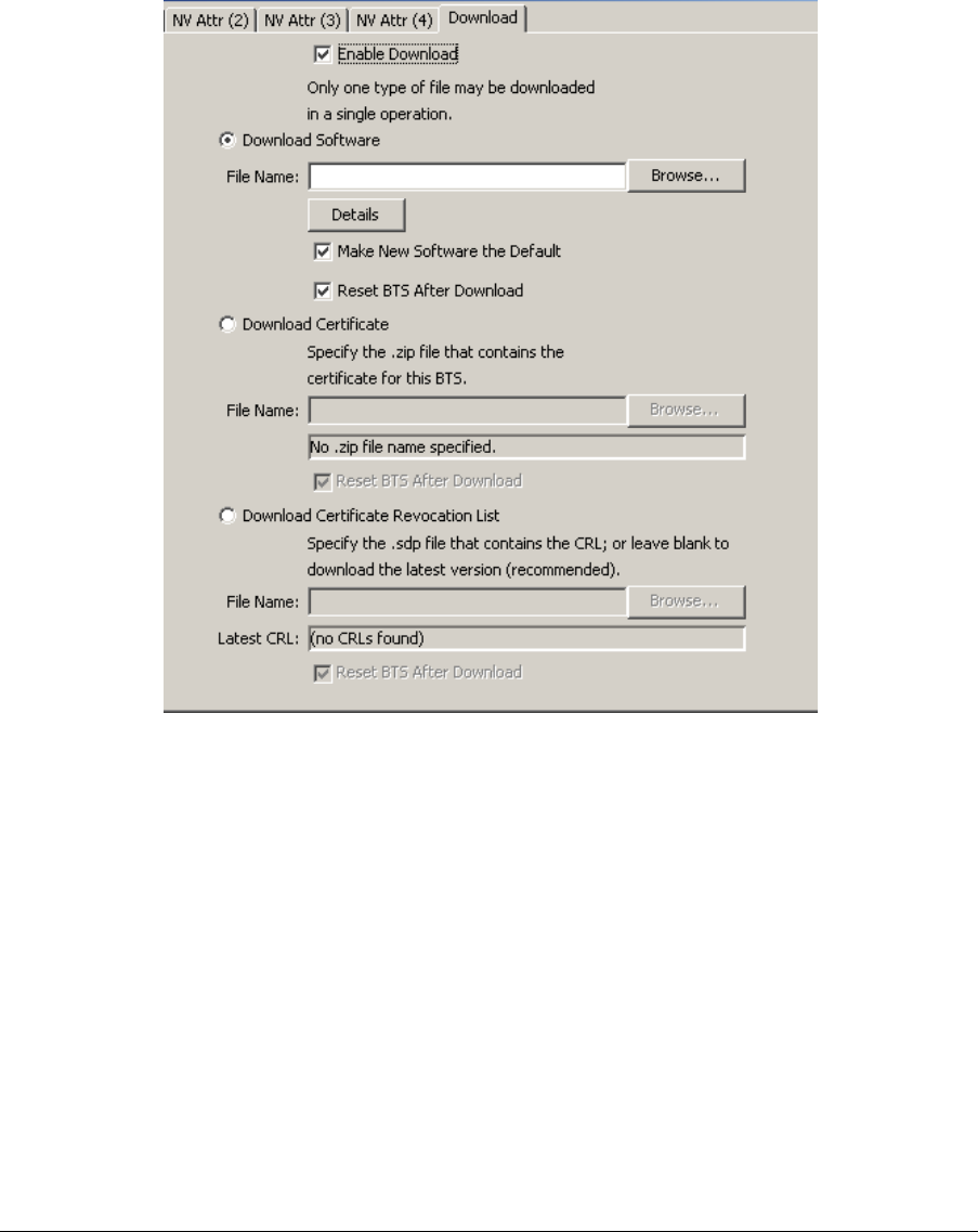
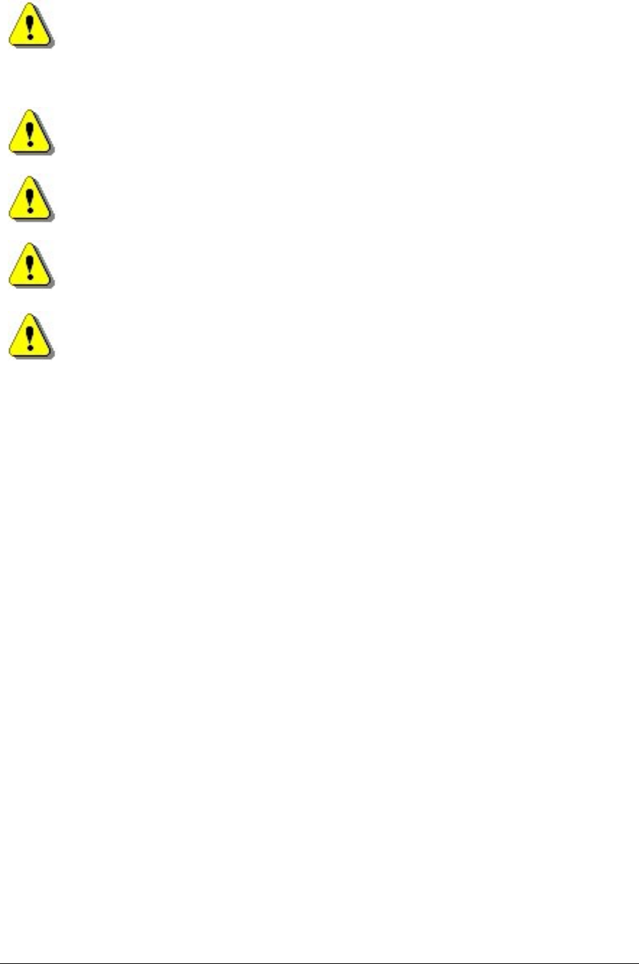
4.2 Software Download
Download any required files to the nanoBTS including:
• Software
• Certificate
• Certificate revocation list
1. In the BTS Status section, click Edit. The BTS Configuration dialog is displayed.
2. On the Download tab, select the Enable Download check box.
3. Select Download Software, then click Browse and navigate to the software
file.
4. Select the Make New Software the Default check box.
5. Select the Reset BTS After Download check box.
6. Click OK.
7. Click Action. The Configure BTS dialog is displayed.
8. Click Download Software. A progress dialog is displayed as the software
downloads.
9. Click Set Current SW. The BTS dialog displayed enables selection of the Boot
Code software, Backhaul software, and TRX software.

nanoBTS Installation Manual Commission a nanoBTS
© ip.access Ltd Page 36
10. Select the required software versions. The software version number is described
by HWTe00s-vxxxxx
Where:
HWT indicates hardware type (nanoBTS model)
• 120 = Model 139/140
• 119 = Model 108/110
• 168 = Model 165
e indicates encryption algorithms
• a = A5/1 and A5/2 encryption algorithms
• b = A5/2 encryption algorithm only
• c = no encryption
00s indicates software type
• 001 = TRX software
• 002 = backhaul software
• 004 = bootcode software
Vxxxxx indicates software version and build number.
11. Select the Reinitialize BTS After Setting Current SW check box.
12. Click OK.
4.3 RF Planning with Network Listen
The Network Listen feature is used to aid frequency planning. It is controlled by BTS
Installer. When Network Listen is activated, the nanoBTS is placed in receive mode and
can be used to identify other nanoBTS, and monitor their power levels, frequency usage
and BCCH information.
1. Ensure that the new nanoBTS is selected in the BTS Status section, and then
click Listen. The Network Listen dialog is displayed.
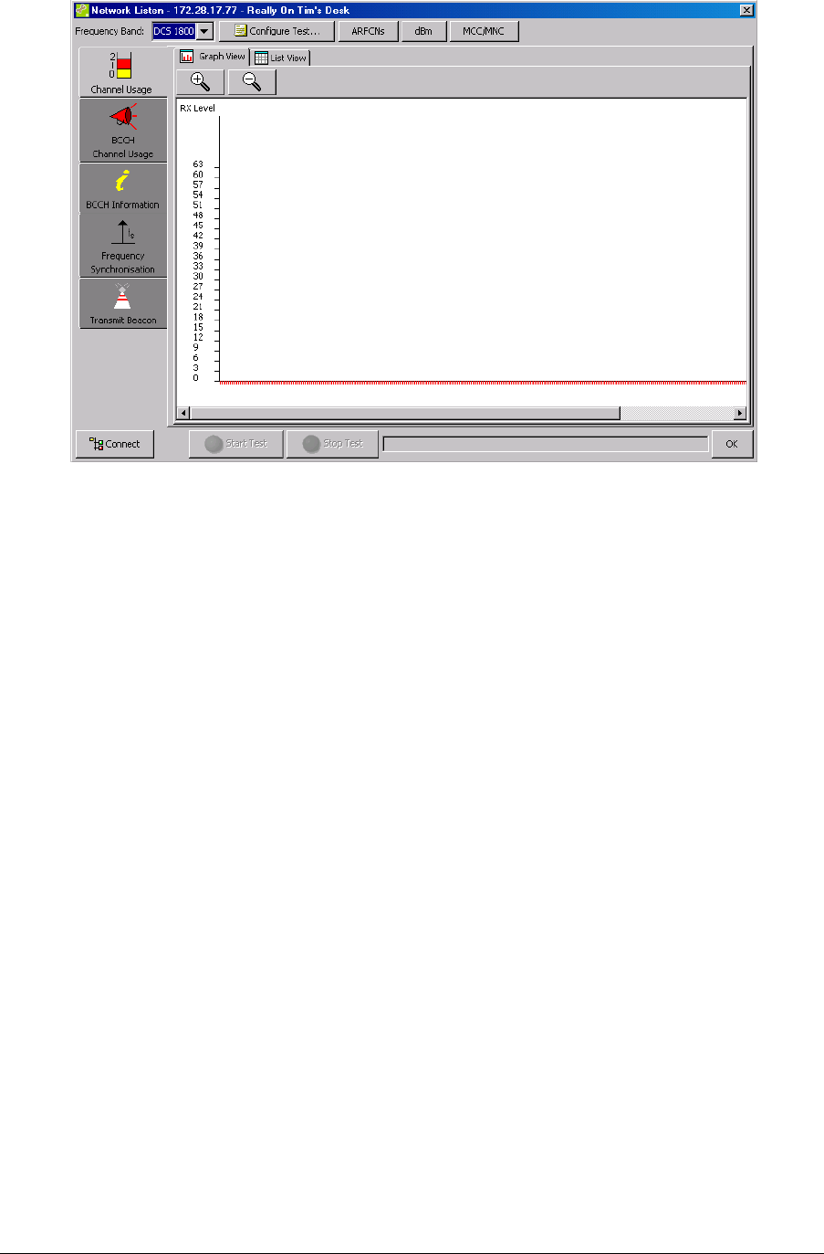
nanoBTS Installation Manual Commission a nanoBTS
© ip.access Ltd Page 37
2. In the Frequency Band drop-down list, ensure that the correct GSM band is
selected.
3. Click Connect. It will take approximately 90 seconds to create the connection
from BTS Installer to the nanoBTS. When the connection is complete, the
message Ready to run test is displayed in the status pane at the bottom of
the dialog and the Status Indicator on the nanoBTS will flash green.
4. Click Channel Usage on the left side of the dialog. The options on the left side of
the dialog are the Network Listen tests.
5. Click Start Test.
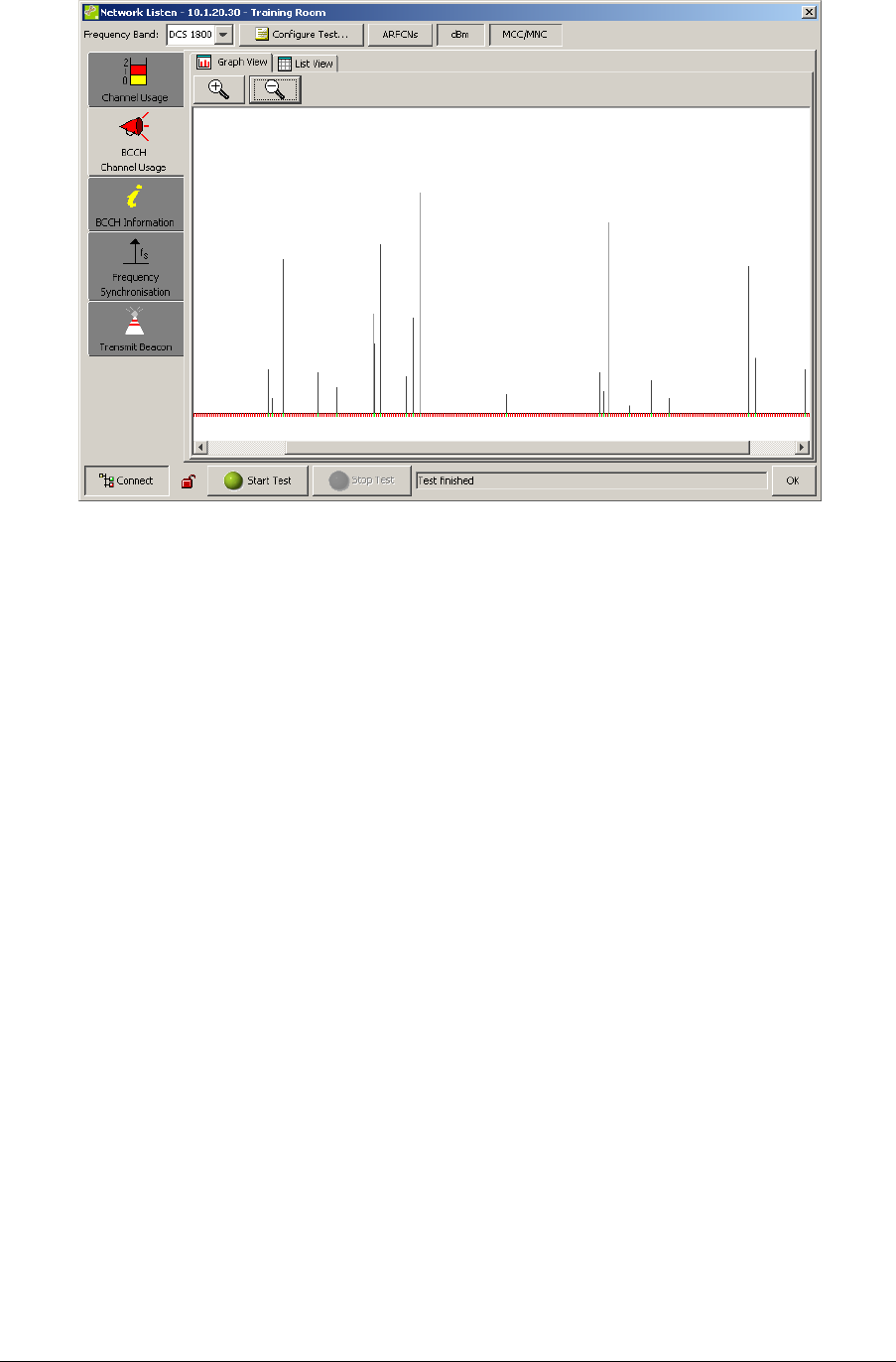
6. When the Channel Usage test is complete, click BCCH Channel Usage.
7. Click Configure Test.
8. Make the required settings in the Configure Test dialog. The BCCH Channel
Usage test reports on channels containing a GSM frequency correction and
synchronisation burst. For more information see [OPM_300].
9. Click Start Test. When the test is complete, the results are displayed in a graph.
nanoBTS Installation Manual Commission a nanoBTS
© ip.access Ltd Page 38
4.4 Frequency Calibration
When the nanoBTS has been installed and configured, the local oscillator must be
calibrated.
The frequency calibration should be performed 10 minutes after the nanoBTS has been
powered up. This provides time for the oscillator to stabilise. The frequency calibration
should then be performed again 24 hours after the nanoBTS has been powered up.
The frequency calibration can be performed in two ways.
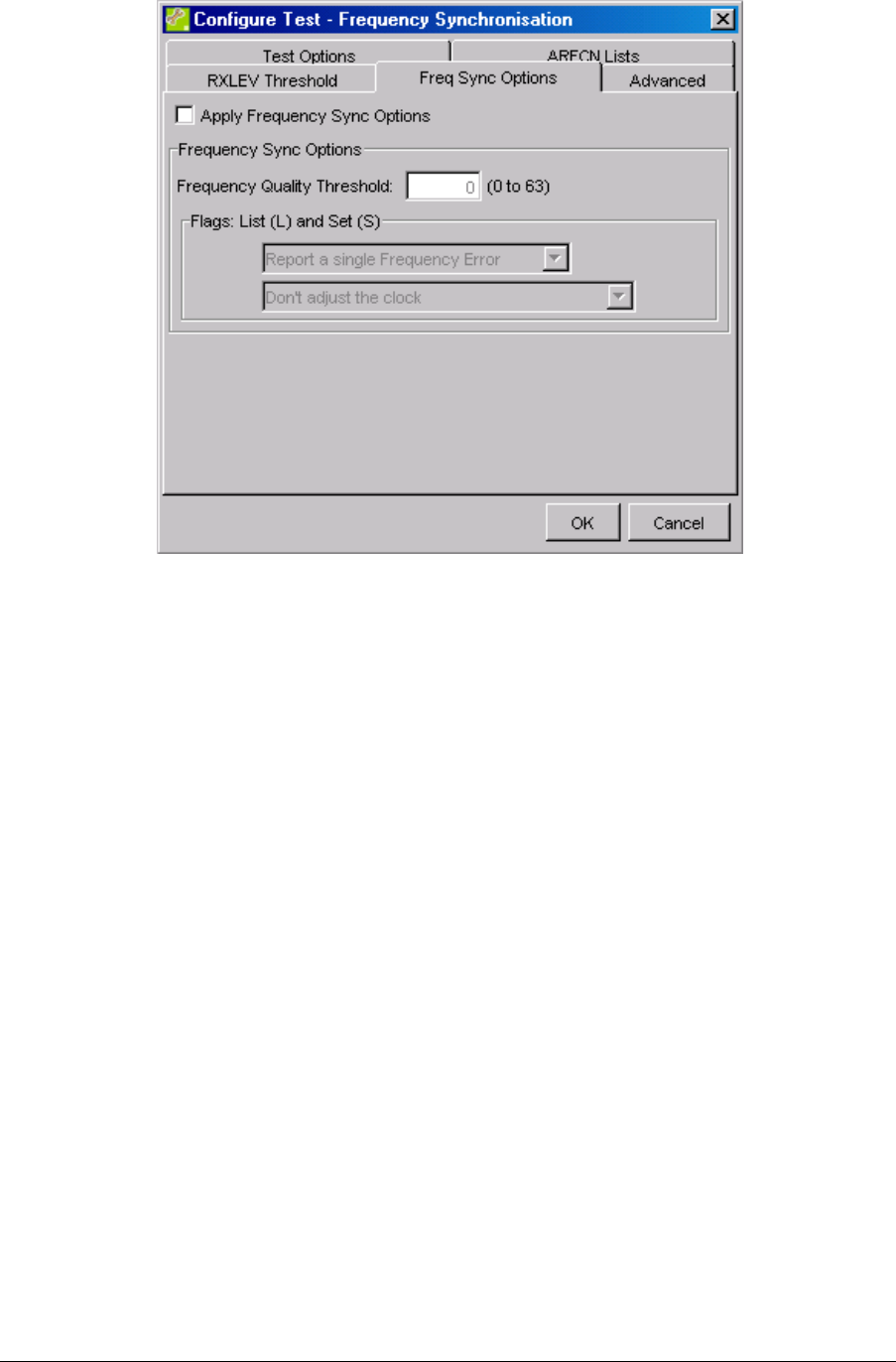
4.4.1 Frequency Synchronisation (Recommended)
The Frequency Synchronisation test in the Network Listen dialog can be used to calibrate
the nanoBTS.
During this test the nanoBTS measures the frequency error of the local oscillator relative to
the measured channel. The frequency errors are reported and the local oscillator can be
adjusted to reduce the error.
Note: The nanoBTS can only adjust its clock if the internal OCXO is the active clock
source.
1. Click Frequency Synchronisation.
2. Click Configure Test.
3. Make the required settings in the Configure Test dialog. To correct the reported
frequency errors select the Apply Frequency Sync Options check box, and
then select Adjust the clock to correct the reported errors from
the Flags Set drop-down list.
nanoBTS Installation Manual Commission a nanoBTS
© ip.access Ltd Page 39
4. Click OK.
5. Click Start Test.
Note: The nanoBTS may not be able to correct the frequency error in one go. It may
be necessary to re-run this test a few times to get the error down to a
reasonable level.
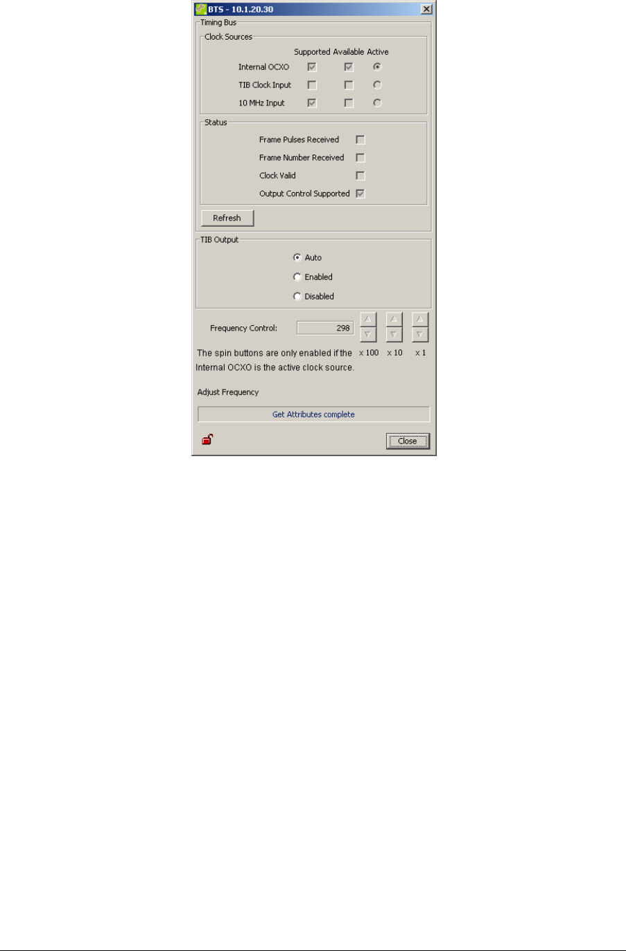
4.4.2 Frequency Control
Frequency Control enables the user to make manual adjustments to the nanoBTS clock
frequency via the Frequency Control attribute, which is represented as a number of ppb
(parts per billion) from a nominal value. It also enables the user to view the Timing Bus
status.
1. Connect external frequency measuring equipment to the nanoBTS TIB Out port.
Note: The external frequency counter should be referenced to an accurate and
stable source.
Note: If the nanoBTS is used in a Multi-TRX configuration, then the TIB Out must
be disconnected from each nanoBTS in the chain prior to calibration and
reconnected afterwards.
2. Ensure that the new nanoBTS is selected in the BTS Status section, and then
click Action. The Configure BTS dialog is displayed.
3. Click Frequency Control. If the nanoBTS has been powered up for more than 24
hours the Frequency Control dialog is displayed.
nanoBTS Installation Manual Commission a nanoBTS
© ip.access Ltd Page 40
Note: If the nanoBTS has not been powered up for 24 hours, a warning message
will be displayed. The warning messages re-iterate the importance of waiting
24 hours before performing the final calibration. To continue with the
calibration, click OK to display the Frequency Control dialog.
Note: The frequency of a nanoBTS can only be adjusted manually if Internal
OCXO is the active clock source. If the Internal OCXO is not the active clock
source and the nanoBTS being adjusted is a master, remove its 10 MHz
input.
4. If required, click Enabled in the TIB Output section.
5. Use the Frequency Control spin buttons to adjust the internal OCXO frequency
while observing the effects in real-time using the external measuring equipment.
The frequency can be adjusted in steps of x1, x10 or x100.
Note: The ideal tolerance range for Freq Qual is 50...63, for Freq Error -50...0...50.
6. When the nanoBTS is set to the required frequency (26 MHz for nanoBTS models
that are not multi-TRX capable, 1.625 MHz for nanoBTS models that are multi-
TRX capable) and within the required tolerance, stop.
7. Click Close. If any settings have been changed in the Frequency Control dialog, a
warning message is displayed that enables these settings to be returned to their
earlier values.
nanoBTS Installation Manual Commission a nanoBTS
© ip.access Ltd Page 41
4.5 nanoBTS Security
BTS Installer is capable of connecting to a nanoBTS using an authenticated encrypted
SSL (secure sockets layer) connection.
Before an SSL connection can be set up you must:
• Ensure that BTS Installer in correctly installed on Windows 2000 SP2 or Windows
XP SP2.
• Install the Aladdin eToken run-time environment
• Be able to export the cryptographic technology to the BTS
1. Plug the eToken into a USB port on the local terminal. The new hardware wizard
is displayed.
2. Permit the new hardware wizard to run, and allow the system to install the
requested certificates.
3. Start BTS Installer. BTS Installer detects the eToken and prompts for a password.
4. Enter the correct password for the eToken connected to the local terminal.
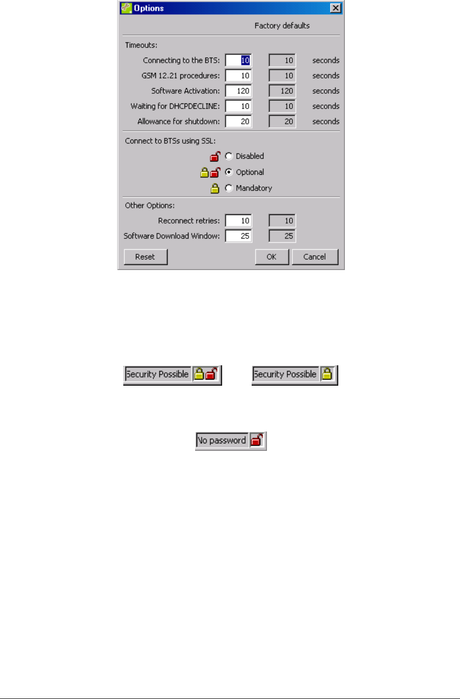
5. In the Options section of BTS Installer, click Configure. The Options dialog is
displayed.
nanoBTS Installation Manual Commission a nanoBTS
© ip.access Ltd Page 42
6. In the Connect to BTSs using SSL section, select either Optional or
Mandatory.
7. Click OK.
The Status bar at the bottom of the BTS Installer indicates that a secure connection is
possible by displaying a closed padlock.
or
If there is a problem and a secure connection is not possible, then an open padlock will be
displayed with a description of the error.
In the example above, the wrong password was entered for the eToken. Alternatively, a
secure connection may not be possible if a security certificate has not been downloaded to
the nanoBTS.
To investigate the status of BTS security:
1. Ensure that the new nanoBTS is selected in the BTS Status section, and then
click Action. The Configure BTS dialog is displayed.
2. Click Security.
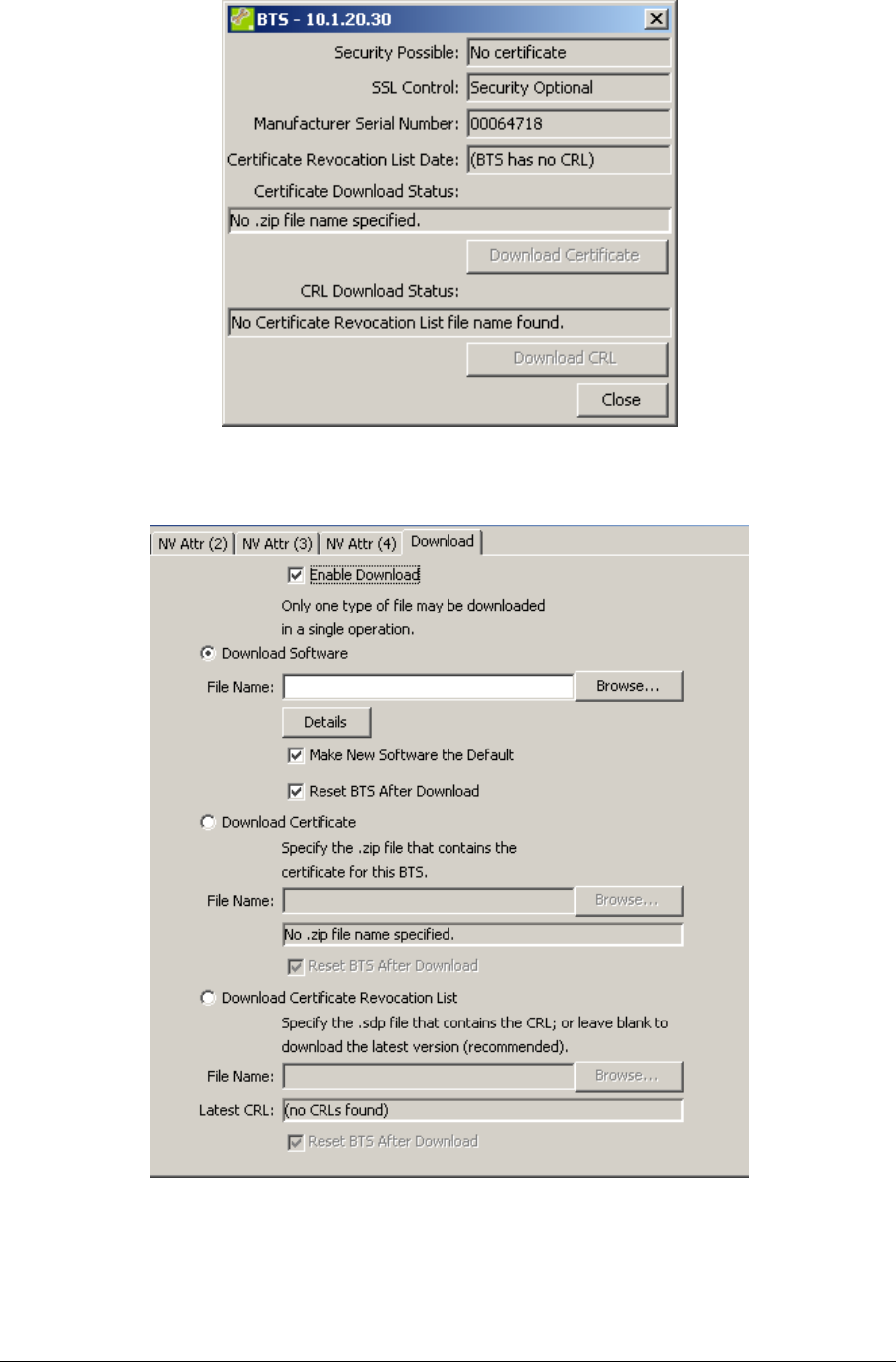
nanoBTS Installation Manual Commission a nanoBTS
© ip.access Ltd Page 43
To download the security certificate and certificate revocation list, follow the steps in
section 0 and use the Download Certificate and Download Certificate Revocation List
options on the Download tab of the BTS Configuration dialog (see below).

nanoBTS Installation Manual nanoBTS and PSU Regulatory Information
© ip.access Ltd Page 44
5 NANOBTS AND PSU REGULATORY INFORMATION
This chapter provides the customer with safety and regulatory warnings, cautions and
information for the ip.access Ltd range of products.
Products covered are the model 108, 110, 139, 140, 165 and 178 range of nanoBTSs and
model 109 and 126 power supplies.
5.1 Terminology
UL Underwriters Laboratories
FCC Federal Communications Commission
IC Industry Canada
CE European Union
5.2 nanoBTS Products
5.2.1 nanoBTS - Handbook - Warnings and Cautions
This system is designed to be operated indoors as a fixed system device and
must be located either on or near the ceiling away from the user. It must be
mounted in a manner to ensure that all users and bystanders are kept a
minimum of 20cm away from the integral antennas at all times.
Do not touch or move the antenna(s) while the unit is transmitting or receiving.
Do not hold any component containing a radio such that the antenna is very
close to or touching any exposed parts of the body, especially the face or eyes
while transmitting.
In most parts of the world, regulatory approval(s) are needed before the
nanoBTS is operated.
Do not connect any device other than the nanoBTS to any RJ45 socket that has
been enabled for nanoBTS connection (i.e. 48Vdc operation).
The nanoBTS is intended for dry indoor applications only. If evidence of
condensation is present do not apply power to the nanoBTS.
nanoBTS Installation Manual nanoBTS and PSU Regulatory Information
© ip.access Ltd Page 45
The nanoBTS must only be powered using an ip.access model 109 PSU (PPI
part number ILA1711112) or ip.access model 126 Ethernet switch and power
inserter (unless prior written approval is obtained from IP Access). Model 165
BTS’s may also be powered by a direct 48V connection using a PSU specified in
writing by IP Access Ltd.
PSU’s supplied by ip.access must not be used for powering any other equipment
(unless carried out in a manner having prior written approval from IP Access).
TIB ports on the NanoBTS may only be connected with ip.access supplied
cables with part numbers 139-040, 139-041, 139-042, 139-043 or 165-076.
Fitting external antenna or antenna cabling to the BTS invalidates the type
approval, CE marking and UL listing referred to herein (unless carried out in a
manner having prior written approval from IP Access).
Maximum cable length from the Ethernet Hub, Switch or PSU is limited to 100m.
5.2.2 nanoBTS - Handbook - Parts Required for each nanoBTS
• Wall Fixings: These are not normally provided as part of the nanoBTS but should be
suitable for the wall material and weight of the nanoBTS (2.7kg). Suggested
materials are 4 x 30mm no.10 woodscrews or M5 bolts and wall plugs (if required).
• PSU.
• NanoBTS complete with mounting bracket.
• RJ45-RJ45 connecting leads.
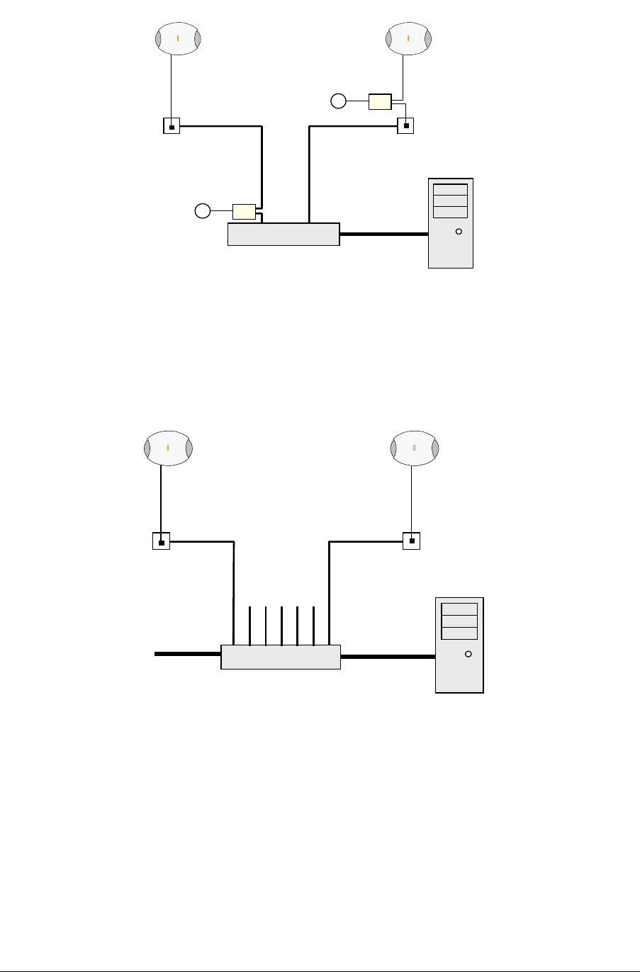
5.2.3 nanoBTS - Handbook - Provision of Power to the nanoBTS
Power for the NanoBTS may be inserted at either the RJ45 outlet or at the output of the
last Ethernet switch/hub/router etc. see figure below.
nanoBTS Installation Manual nanoBTS and PSU Regulatory Information
© ip.access Ltd Page 46
Ethernet Switch
nanoBTS nanoBTS
BSC
RJ45
(48v)
~
~
RJ45
PSU φ
φφ
φ
PSU θ
θθ
θ
θ
θθ
θPSU located at the switch
φ
φφ
φPSU located at nanoBTS
When using the ip.access model 126A Ethernet Switch and Power Inserter, external PSU’s
are not required, the NanoBTS is connected locally or via site cabling to the powered ports
of the 126.
and 48V Power Inserter
nanoBTS (max qty 7)
BSC
RJ45
(48v)
~
RJ45
(48V)
126A Ethernet Switch
Ethernet
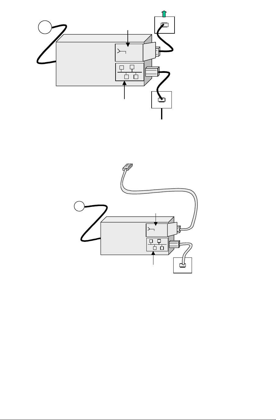
5.2.3.1 nanoBTS - Handbook - Installing the PSU at the Ethernet Switch.
If the 109 PSU is located at the patch panel /output port of the Ethernet switch, it is
important that the 109 PSU is connected exactly as illustrated below (failure to do so may
cause damage to the switch). Ensure that the 109 PSU is placed in a location that is
ventilated and that the connection leads provide no safety hazard.
nanoBTS Installation Manual nanoBTS and PSU Regulatory Information
© ip.access Ltd Page 47
~
PSU
48Vdc
48Vdc
!
110-230Vac
RJ45
Connection to LAN
Connection to nanoBTS
Cable to nanoBTS
Ethernet Switch
5.2.3.2 nanoBTS - Handbook - Installing the PSU at the nanoBTS.
Ensure that the 109 PSU is placed in a location that is ventilated and that the connection
leads provide no safety hazard.
RJ45
Connection to LAN
~
PSU
48Vdc
48Vdc
!
110-230Vac
Connection to nanoBTS
5.2.4 nanoBTS - Handbook – FCC Text
Standards
• FCC Rule 47 Parts 2, 15, 24
Note:
Changes or modifications not expressly approved by the party responsible for
compliance may void the user's authority to operate this equipment.
Model 110 NanoBTS has FCC ID QGGM180TVX
Model 140 NanoBTS has FCC ID QGGKU02ZZT
Model 165B NanoBTS has FCC ID QGGKU02ZZP
Model 165D NanoBTS has FCC ID QGGKU02ZZR
Model 165F nanoBTS has FCC ID QGGKU02ZZP
Model 165H nanoBTS has FCC ID QGGKU02ZZS

nanoBTS Installation Manual nanoBTS and PSU Regulatory Information
© ip.access Ltd Page 48
Federal Communications Commission
Note:
This equipment has been tested and found to comply with the limits for a
class A digital device, pursuant to part 15 of the FCC rules. These limits are
designed to provide reasonable protection against harmful interference when
the equipment is operated in a commercial environment. This equipment
generates, uses, and can radiate radio frequency energy and, if not installed
and used in accordance with the instruction manual, may cause harmful
interference to radio communications. Operation of this equipment in a
residential area is likely to cause harmful interference in which case the user
will be required to correct the interference at his own expense.
5.2.5 nanoBTS - Handbook – IC Text
Standards
• RSS133 issue 2
Note:
Changes or modifications not expressly approved by the party responsible for
compliance may void the user's authority to operate this equipment.
Model 110 NanoBTS has IC (Industry Canada) ID 4644B-M180TVX
Model 140 NanoBTS has IC (Industry Canada) ID 4644A-KU02ZZT
Model 165B NanoBTS has IC (Industry Canada) ID 4644A-KU02ZZP
Model 165D NanoBTS has IC (Industry Canada) ID 4644A-KU02ZZR
Model 165F NanoBTS has IC (Industry Canada) ID 4644A-KU02ZZP
5.2.6 nanoBTS – Handbook - Regulatory Compliance Statement
The nanoBTS conforms to the following regulatory standards.
5.2.6.1 Type Approvals
• GSM essential requirements under article 3.2 of the R&TTE directive ETSI EN 301
502. CE Marking (CE0168).
• FCC - see above
• IC – see above
5.2.6.2 EMC Standards
• ETSI EN 301 489-1 and –8, ETSI EN 301 502
• FCC - see above
• IC – see above
5.2.6.3 Environmental Standards
• ETS 300 019
nanoBTS Installation Manual nanoBTS and PSU Regulatory Information
© ip.access Ltd Page 49
5.2.6.4 Safety Standards
• EN60950 (CE Marking)
• IEC 60950
• UL60950 Listed (file number E230296, USA and Canada)
• CB Certificate
This product is intended for use in all
Member States of the European Union.
"Hereby, ip.access declares that this NanoBTS is in compliance with the essential
requirements and other relevant provisions of Directive 1999/5/EC."
A copy of regulatory compliance documentation may be obtained in writing from
"IP access Ltd, Building 2020, Cambourne Business Park, Cambourne, Cambridge, CB23
6DW, UK".
5.3 Model 109 Power Supply
5.3.1 109 - Handbook - Warnings and Cautions
This document is written in English, please request a copy in your local
language if required.
This product is only intended to power products approved by IP Access.
Ensure that only IP Access products are connected to an Ethernet circuit
enabled for 48V operation, this also applies to outlets remote from the unit.
For indoor use only, output cabling is SELV / LAN for indoor routing only.
Do not cover casing or otherwise impede cooling.
Do not apply power to unit if there is any evidence of condensation.
Do not open casing as mains voltages may be present within the unit.
90 to 264VAC input is via a 2 pin IEC C7 (figure 8) connector. Inlet cable
assembly must carry a suitable local approval (e.g. UL marked for US and
Canadian markets).

nanoBTS Installation Manual nanoBTS and PSU Regulatory Information
© ip.access Ltd Page 50
5.3.2 PSU109 – Environmental Specification
• -10 to +45 degrees Centigrade ambient operating temperature.
• This product has been listed by UL for use in a 25 degree C ambient.
• -20 to +80 degrees C ambient storage temperature.
• 5 to 95% RH non condensing humidity.
5.3.3 109 - Handbook - FCC Text
WARNING
This is a class B product. In a domestic environment this product may cause radio
interference in which case the user may be required to take adequate measures.
Federal Communications Commission
Note:
This equipment has been tested and found to comply with the limits for a
class B digital device, pursuant to part 15 of the FCC rules. These limits are
designed to provide reasonable protection against harmful interference when
the equipment is operated in a commercial environment. This equipment
generates, uses, and can radiate radio frequency energy and, if not installed
and used in accordance with the instruction manual, may cause harmful
interference to radio communications. Operation of this equipment in a
residential area is likely to cause harmful interference in which case the user
will be required to correct the interference at his own expense.
5.3.4 109 – Handbook - Industry Canada text
This Class B digital apparatus complies with Canadian ICES-003.
Cet appareil numériqué de la classe B est conformé à la norme NMB-003 du
Canada.
5.3.5 109 – Handbook - Regulatory Compliance Statement
5.3.5.1 EMC Standards
• EN 55022 and EN55024 (CE marked)
• FCC Part 15 class B
• ICES-003
5.3.5.2 Safety Standards
• EN60950 (CE marked)
• UL60950 Listed (File number E231617) (USA and Canada)
nanoBTS Installation Manual nanoBTS and PSU Regulatory Information
© ip.access Ltd Page 51
This product is intended for use in all
Member States of the European Union.
"Hereby, ip.access declares that this Ethernet Power Inserter is in compliance with the
essential requirements and other relevant provisions of Directives 73/23/EEC and
89/336/EEC."
The PSU109 is supplied by Poly-Products Industries, model number ILA1711112.
A copy of regulatory compliance documentation may be obtained in writing from
"IP access Ltd, Building 2020, Cambourne Business Park, Cambourne, Cambridge, CB23
6DW, UK".
5.4 Model 126 Ethernet Switch and Power Inserter
5.4.1 126 - Handbook - Warnings and Cautions
This document is written in English, please request a copy in your local
language if required.
This product is only intended to power products approved by IP Access.
Ensure that only IP Access approved products are connected to an Ethernet
circuit enabled for 48V operation, this also applies to outlets remote from the
unit.
To be located in a restricted access location only (accessible to maintenance
personnel only).
For indoor use only, output cabling is SELV / LAN for indoor routing only.
Do not block ventilation holes or otherwise impede cooling.
Refer to National Engineering Code (USA). Wiring methods must be in
accordance with NEC Article 300.
When rack mounting, secure via front panel plate with 4 bolts and ensure that no
additional load is placed upon the caseworks (e.g. heavy objects on top).
When rack mounting, ensure that the internal rack temperature does not exceed
the rating of this product.
nanoBTS Installation Manual nanoBTS and PSU Regulatory Information
© ip.access Ltd Page 52
Do not apply power to unit if there is any evidence of condensation.
Do not open casing as mains voltages may be present within the unit.
AC inlet cable must carry suitable local approval (e.g. UL marking for US and
Canadian markets).
5.4.2 126 - Input Power Source Specification
• Unit may be powered via AC or DC (not both).
• 90 to 132 and 180 to 264VAC (auto-ranging) via an IEC C13 connector. 135W, 2A
rating.
• 47 to 57V DC via screw terminals on the front panel. 115W 3A rating. The installer
must ensure that this supply connection is fused externally at 5A and provision is
made for an external disconnection device.
• Appliance must be earthed, either via the mains connector (mains operation) or
screw terminal on the front panel (DC operation).
5.4.3 126 – Environmental Specification
• -5 to +45 degrees C ambient operating
• -20 to +80 degrees C ambient storage
• 5 to 95% RH non condensing
5.4.4 126 – Handbook - FCC Text
WARNING
This is a class A product. In a domestic environment this product may cause radio
interference in which case the user may be required to take adequate measures.
Federal Communications Commission
Note: This equipment has been tested and found to comply with the limits for a
class A digital device, pursuant to part 15 of the FCC rules. These limits are
designed to provide reasonable protection against harmful interference when
the equipment is operated in a commercial environment. This equipment
generates, uses, and can radiate radio frequency energy and, if not installed
and used in accordance with the instruction manual, may cause harmful
interference to radio communications. Operation of this equipment in a
residential area is likely to cause harmful interference in which case the user
will be required to correct the interference at his own expense.

nanoBTS Installation Manual nanoBTS and PSU Regulatory Information
© ip.access Ltd Page 53
5.4.5 126 – Handbook - Industry Canada text
This Class A digital apparatus complies with Canadian ICES-003.
Cet appareil numériqué de la classe A est conformé à la norme NMB-003 du
Canada.
5.4.6 126 – Handbook - Regulatory Compliance Statement
The nanoBTS conforms to the following regulatory standards.
5.4.6.1 EMC Standards
• EN 55022 and EN55024 (CE marked)
• FCC Part 15 class A
• ICES-003
5.4.6.2 Safety Standards
• EN60950 (CE marked)
• IEC 60950
• UL60950 Listed (File number E230296) (USA and Canada)
• CB certificate (DK-7033)
This product is intended for use in all
Member States of the European Union.
"Hereby, ip.access declares that this Ethernet Switch / Power Inserter is in compliance
with the essential requirements and other relevant provisions of Directives 73/23/EEC and
89/336/EEC."
A copy of regulatory compliance documentation may be obtained in writing from
"IP access Ltd, Building 2020, Cambourne Business Park, Cambourne, Cambridge, CB23
6DW, UK".