ip access KU02ZZT GSM1900 picocellular basestation User Manual 110 010XA GDE
ip.access ltd GSM1900 picocellular basestation 110 010XA GDE
UserManual.wiki
>
ip access
>
KU02ZZT User Manual
Installation and Configuration
Navigation menu
Upload a User Manual
Namespaces
Wiki Guide
HTML
PDF
Info
Views
User Manual
Discussion / Help
Navigation
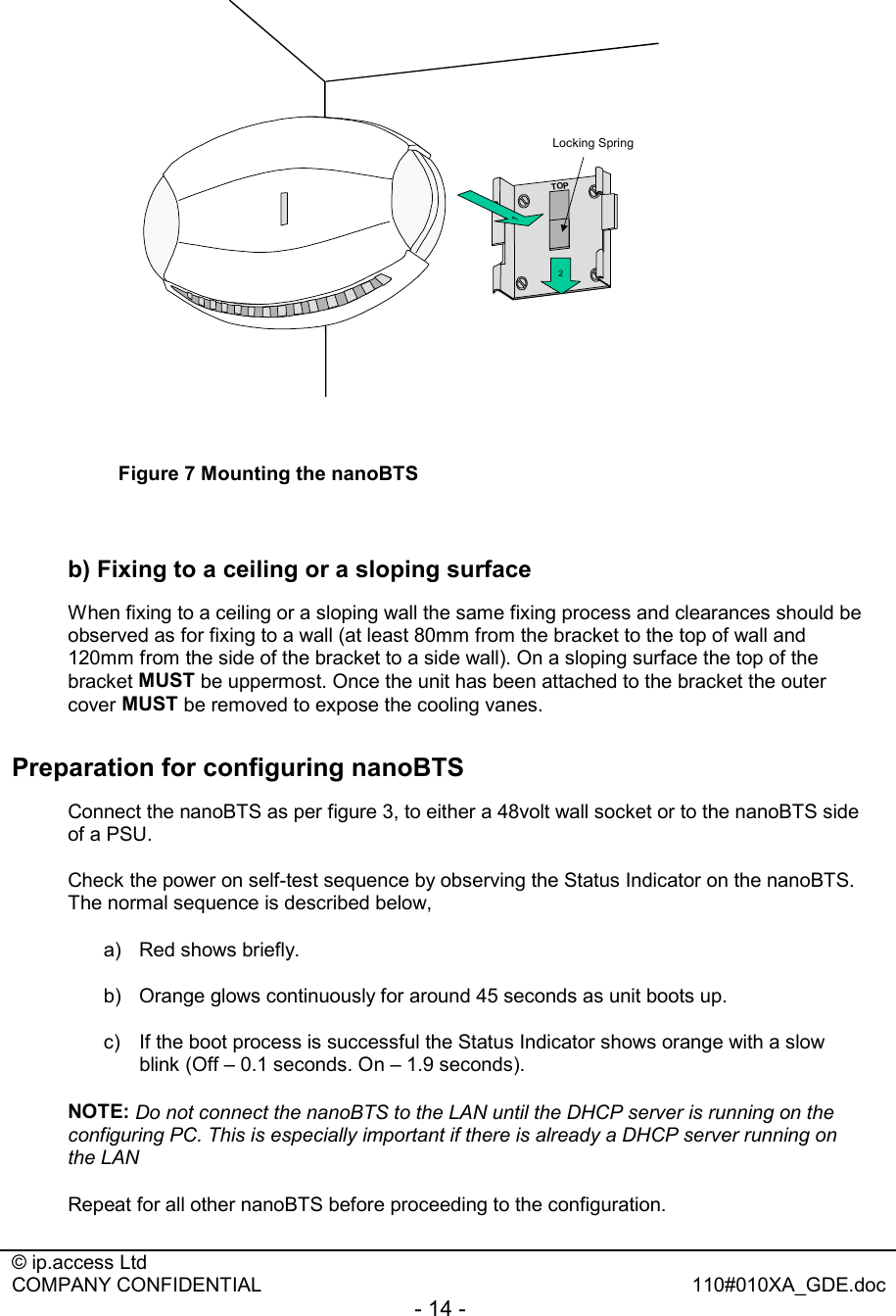
![© ip.access Ltd COMPANY CONFIDENTIAL 110#010XA_GDE.doc - 16 - # you can specify any of the following options per MAC address line: # ipaddr= # subnet= # router= # lease-time=3600 # filename= # next-server= # omlipaddr = 172.28.0.30 # omlipport = 3002 # 2ndomlipaddr = 172.28.0.30 # 2ndomlipport = 3006 # location = "On my desk" # btsid = 42 # trxid = 0 # # NOTE that MAC addresses are case sensitive and should be in lower case. 00:02:95:00:00:0a ipaddr=172.28.6.10 btsid=1 location=”room 1” 00:02:95:00:00:03 ipaddr=172.28.6.3 btsid=2a location="room 2 west wall" 00:02:95:00:00:04 ipaddr=172.28.6.4 btsid=2b location="room 2 east wall" 00:02:95:00:00:05 ipaddr=172.28.6.5 btsid=3 location=”reception” Update the file to reflect the settings specified in the site configuration plan. The DHCP server uses this file, to pass all of the configuration information, including the IP address to the nanoBTS, and then stores the IP address as a fixed address. Note: If no software is to be downloaded to the nanoBTS, the [filename] field should be left blank. Step 2. Connecting the nanoBTS Connect all the RJ45s to the switch. Start the DHCP server and the TFTP server by running C:\ipaccess\tools\windhcpd\windhcpd.exe (or use the desktop icon). The following screens are displayed when the servers are running and no further intervention is required, as the servers will automatically respond to requests from the nanoBTS. Figure 8 DHCPD server](https://usermanual.wiki/ip-access/KU02ZZT/User-Guide-353106-Page-16.png)
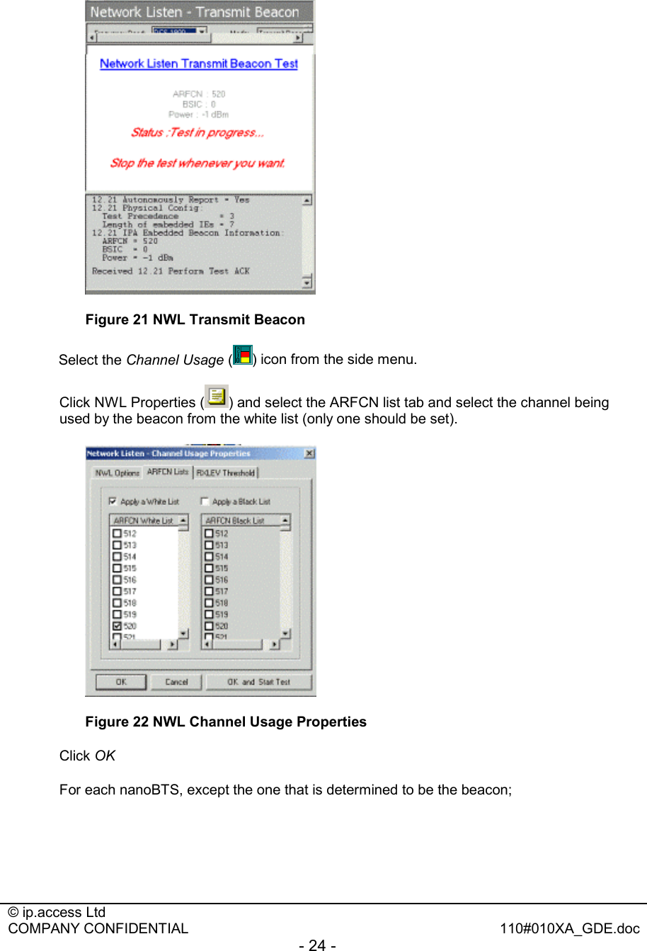
![© ip.access Ltd COMPANY CONFIDENTIAL 110#010XA_GDE.doc - 25 - Select the Channel Usage ( ) icon from the side menu and then Test Start ( ) from the main menu bar. Figure 23 NWL Channel Usage measurement From the displayed bar chart note the reading. In the example above the value shown is –65dbm Calculate the path loss by subtracting the RX level from the TX level i.e. [=23dBm TX] – [-65dBm RX] = 88dB path loss. Record the path losses in the path loss matrix spreadsheet contained within the installation report. Calculate and record the transmit power level for each nanoBTS so that the received power level, detected by at least two neighbouring BTS shall typically be -85dBm and will be specified in the "Site Configuration Plan" Select the window for the beacon nanoBTS, and click on the NWL stop ( ) icon. Repeat the test for each nanoBTS in turn; by setting each into transmit beacon test and measuring the path loss between it and each other nanoBTS to complete the matrix.](https://usermanual.wiki/ip-access/KU02ZZT/User-Guide-353106-Page-25.png)