ip access KU02ZZT GSM1900 picocellular basestation User Manual 110 010XA GDE
ip.access ltd GSM1900 picocellular basestation 110 010XA GDE
Installation and Configuration

© ip.access Ltd
COMPANY CONFIDENTIAL 110#010XA_GDE.doc
- 1 -
Product
Defining
Documentation
ip.access Ltd
Melbourn Science Park
Cambridge Road
Melbourn
Royston
Hertfordshire
SG8 6EE
United Kingdom
ip.access
Installation and Configuration
110#010
Author(s)
Carl Melbourne
29/07/2002
© ip.access Ltd
COMPANY CONFIDENTIAL 110#010XA_GDE.doc
- 2 -
The information contained in this document is commercially confidential and
must not be disclosed to third parties without prior consent.

© ip.access Ltd
COMPANY CONFIDENTIAL 110#010XA_GDE.doc
- 3 -
REVISION HISTORY
Version Change Summary Date Author
XA First Release 29/07/2002 CM2

© ip.access Ltd
COMPANY CONFIDENTIAL 110#010XA_GDE.doc
- 4 -
Table of Contents
Table of Figures............................................................................................................................5
Warnings and Cautions................................................................................................................6
Introduction...................................................................................................................................7
The nanoBTS ..............................................................................................................................7
Installing the nanoBTS.................................................................................................................9
Pre-Installation Checklist.............................................................................................................9
Installing the nanoBTS ................................................................................................................9
Unpacking nanoBTS .................................................................................................................10
Provision of Power to the nanoBTS ..........................................................................................11
Installing the PSU at the Ethernet switch. .............................................................................11
Installing the PSU at the nanoBTS. .......................................................................................12
Mounting the nanoBTS..........................................................................................................12
a) Fixing to a wall...................................................................................................................12
b) Fixing to a ceiling or a sloping surface ..............................................................................14
Preparation for configuring nanoBTS........................................................................................14
Configuring the nanoBTS ..........................................................................................................15
Step 1. Setting up PC for configuring nanoBTS ..................................................................15
Step 2. Connecting the nanoBTS........................................................................................16
Step 3. Setting IP addresses and downloading software ....................................................17
Step 4. Calibration of nanoBTS using frequency synchronisation.......................................18
Step 5. Check macro network channel usage.....................................................................19
Step 6. BCCH Channel Usage Test ....................................................................................21
Step 7. Retrieve BCCH frequency information....................................................................21
Step 8. Measuring path loss between nanoBTS .................................................................22
Step 9. Walk Test................................................................................................................26
Step 10. Installation Report ...................................................................................................26
Regulatory Compliance..............................................................................................................27
Appendix 1: Modifying nanoBTS for use with external antenna ...........................................28
Appendix 2: Alternative method to set frequency of nanoBTS oscillator ...........................30
Appendix 3: Commissioning at the nanoBTS.........................................................................34
Appendix 4: Commissioning mostly at the NOC ....................................................................35
Appendix 5 Troubleshooting .....................................................................................................36
Checking that the nanoBTS has successfully downloaded an IP address ...............................36
Resetting the nanoBTS to factory default settings. ...................................................................36
Communication Problems.........................................................................................................37
No LEDs ................................................................................................................................37
LED is on but is flashing orange (1sec on, 1sec off) .............................................................37
No communication between the nanoInstaller and the BTS .................................................37
Clock Adjustment Problems......................................................................................................38
No 26MHz clock during Frequency adjustment.....................................................................38
Unsettled 26MHz during frequency adjustment.....................................................................38
Problems During Beacon Test ..................................................................................................38
No signal seen on other nanoBTS during beacon test ..........................................................38
Glossary of Terms and Abbreviations......................................................................................39

© ip.access Ltd
COMPANY CONFIDENTIAL 110#010XA_GDE.doc
- 5 -
Table of Figures
Figure 1 System Architecture .........................................................................................................7
Figure 2 nanoBTS...........................................................................................................................8
Figure 3 nanoBTS PSU location...................................................................................................11
Figure 4 PSU location at Switch ...................................................................................................11
Figure 5 Separating nanoBTS and mounting bracket ..................................................................12
Figure 6 Positioning mounting bracket .........................................................................................13
Figure 7 Mounting the nanoBTS...................................................................................................14
Figure 8 DHCPD server................................................................................................................16
Figure 9 TFTP server....................................................................................................................17
Figure 10 TFTP server window when active.................................................................................17
Figure 11 nanoInstaller opening screen .......................................................................................18
Figure 12 BTS Session.................................................................................................................18
Figure 13 RXLEV Threshold.........................................................................................................19
Figure 14 Freq Sync Options ........................................................................................................19
Figure 15 NWL Test Results ........................................................................................................20
Figure 16 BCCH Information Properties.......................................................................................21
Figure 17 BCCH Information Test Results ...................................................................................22
Figure 18 BTS Session.................................................................................................................23
Figure 19 Transmit Beacon Properties: NWL options ..................................................................23
Figure 20 Transmit Beacon Properties: Beacon Information........................................................23
Figure 21 NWL Transmit Beacon .................................................................................................24
Figure 22 NWL Channel Usage Properties ..................................................................................24
Figure 23 NWL Channel Usage measurement ............................................................................25
Figure 24 Removal of antenna covers..........................................................................................28
Figure 25 Removal of antenna cover body...................................................................................28
Figure 26 Fit clamp plate ..............................................................................................................29
Figure 27 NanoInstaller Opening Screen .....................................................................................30
Figure 28 BTS Session.................................................................................................................30
Figure 29 nanoInstaller after connection to the nanoBTS ............................................................31
Figure 30 Get NV Attributes..........................................................................................................31
Figure 31 Set NV Attributes ..........................................................................................................32
Figure 32 Frequency Control ........................................................................................................33
Figure 33 Test Setup, Option 1.....................................................................................................34
Figure 34 Bts Finder Opening Screen ..........................................................................................36
Figure 35 Find BTS Results..........................................................................................................36
© ip.access Ltd
COMPANY CONFIDENTIAL 110#010XA_GDE.doc
- 6 -
Warnings and Cautions
This system is designed to be operated indoors as a fixed system device and must be
located either on or near the ceiling away from the user. It must be mounted in a manner
to ensure that all users and bystanders and users are kept a minimum of 60mm away
from antennas at all times.
Do not touch or move the antenna(s) while the unit is transmitting or receiving.
Do not hold any component containing a radio such that the antenna is very close to or
touching any exposed parts of the body, especially the face or eyes while transmitting.
In most parts of the world, regulatory approval(s) are needed before the nanoBTS is
operated.
Do not connect any device other than the nanoBTS to any RJ45 socket that has been
enabled for nanoBTS connection (i.e. 48Vdc operation).
The nanoBTS is intended for dry indoor applications only. If evidence of condensation is
present do not apply power to the nanoBTS.
The nanoBTS must only be powered using a PSU supplied by ip.access.
PSUs supplied by ip.access must not be used for powering any other equipment.
© ip.access Ltd
COMPANY CONFIDENTIAL 110#010XA_GDE.doc
- 7 -
Introduction
The nanoBTS
The nanoBTS is a picocellular basestation operating in one of the GSM frequency bands and
complies with all the relevant ETSI / FCC specifications. A nanoBTS basestation is mounted on a
wall or ceiling, taking its power and traffic from a single 10/100 switched Ethernet connection.
The range of the nanoBTS exceeds half a kilometre in an uncluttered environment and inside
buildings can be expected to support users within a radius of up to 50m or more, depending on
the building construction materials.
The nanoBTS is physically linked to the BSC over an IP network and uses standard GSM
protocols to connect to the existing Public Land Mobile Network (PLMN)
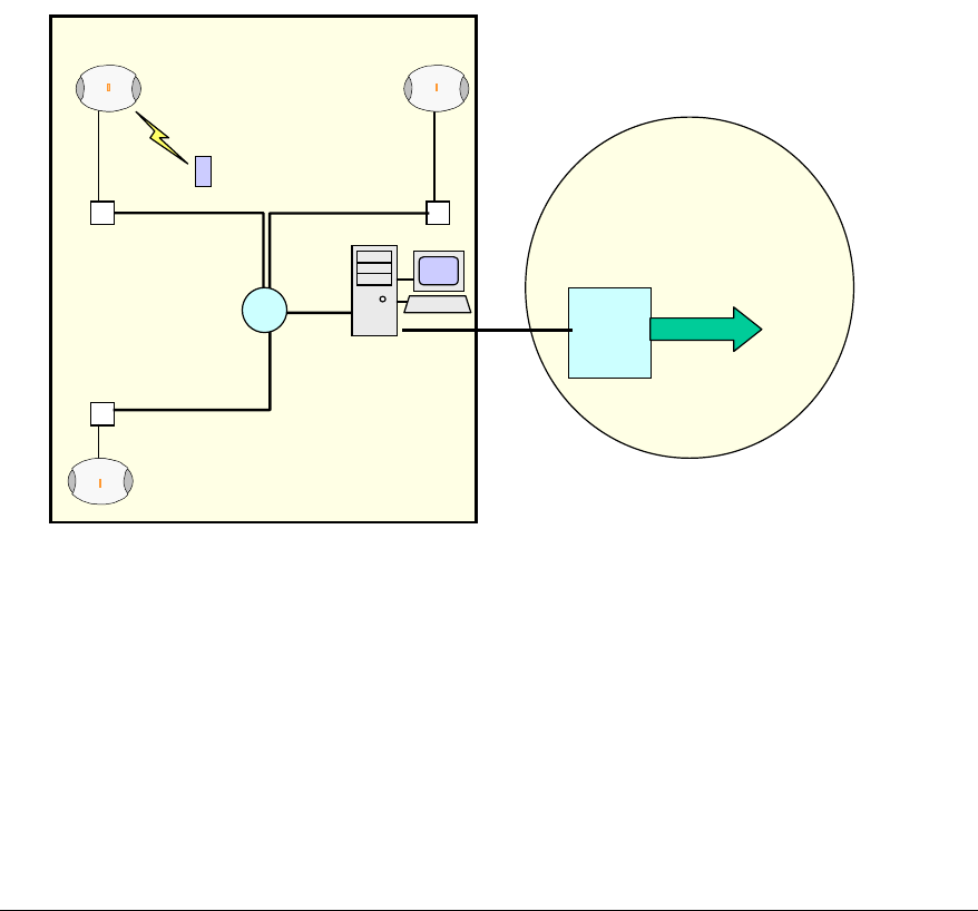
The diagram below shows the system architecture. Calls within the installation are passed over
the IP network and are handed over to the PLMN if the mobile leaves the installation coverage
area and is out of range of the ip.access basestations.
MSC
PLMN
(Public Land Mobile
Network)
Ethernet
Switch
nanoBTS nanoBTS
GSM Phone
Corporate Office
BSC
RJ45(48v)
10/100baseT
Ethernet
Figure 1 System Architecture
© ip.access Ltd
COMPANY CONFIDENTIAL 110#010XA_GDE.doc
- 8 -
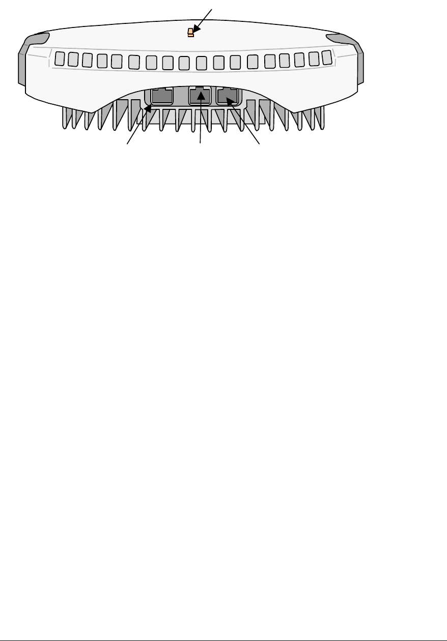
Status Indicator
RJ45(48Vdc)
Ethernet
TIB In
(for future
Expansion)
TIB Out (26MHz)
Figure 2 nanoBTS
The nanoBTS may be mounted on walls or ceilings, in convenient locations chosen at the system
planning stage, to provide adequate coverage in a building. Power to the nanoBTS is via the RJ45
socket enabled for 48Vdc. The nanoBTS has a LED indicator used to convey its status. Note.
This indicator can be disabled after commissioning if required using the nanoBTS installer
software. For wall mounted installations and installations on sloping surfaces it is preferred that
the cable access is from the bottom as this prevents the ingress of dust and condensation, but
where circumstances dictate the nanoBTS may be mounted to allow cables access from the top
of the unit. When mounted on a ceiling the plastic clip-on cover MUST be removed to necessitate
ventilation and cooling.

© ip.access Ltd
COMPANY CONFIDENTIAL 110#010XA_GDE.doc
- 9 -
Installing the nanoBTS
Pre-Installation Checklist
Prior to installation and following a technical site survey, ensure that the following items are
available.
1. Details of placement of PSUs (at central site or at nanoBTS).
2. The following system information is required for each nanoBTS:
• The ARFCN (Absolute Radio Frequency Channel Number) to be allocated to that
cell.
• A specific IP address may be allocated to each nanoBTS location or a pool of IP
addresses may be provided and the installer allocates the IP address for each
nanoBTS.
• Requirements for and details of any external antenna and mounting and locations.
• BTS Id for each nanoBTS.
• IP address subnet mask and default router IP address for the each nanoBTS.
3. For the installation site, the following information is required.
• IP address subnet mask and default router IP address for the installation PC.
• Printout of the site configuration plan produced as a result of the survey
• A floor plan showing the mounting location of each nanoBTS, together with
location name and btsid.
Installing the nanoBTS
Parts required for each nanoBTS:
• Wall fixings: These are not provided as part of the nanoBTS but should be
suitable for the wall material and weight of the nanoBTS (2.7kg). Suggested
materials are 4 x 30mm no.10 woodscrews or M5 bolts and wall plugs (if
required).
• PSU.
• NanoBTS complete with mounting bracket.
• RJ45-RJ45 connecting leads
Tools required:
Installation:
• Drill and masonry or wood bit.
• Mounting bracket removal tool for removal of the bracket from the nanoBTS.
• Spanner or screwdriver suitable for any fixings used for the mounting bracket.

© ip.access Ltd
COMPANY CONFIDENTIAL 110#010XA_GDE.doc
- 10 -
• Ruler dimensioned in mm.
• T20 Torx screwdriver required if external antenna kit is used
Configuration:
• Frequency counter with 12-digit display with a reference oscillator stability better
than 10-9.
• If the reference nanoBTS adjustment is to be performed manually, then an
isolated 10-way RJ45 to BNC lead is required.
• Laptop PC preinstalled with the ip.access “nanoInstaller” and associated
configuration files.
Walk Test:
• A test mobile or other GSM measuring device.
.
Installation Steps
1. Unpack nanoBTS
2. Install PSUs
3. Fix mounting brackets
4. Modify nanoBTS for external antennas (if required)
5. Attach nanoBTS to mounting bracket
6. Record nanoBTS MAC address and location.
Configuration Steps
1. Set up PC for configuring nanoBTS
2. Connect the nanoBTS
3. Set IP address and optionally download operational software
4. Set frequency of nanoBTS oscillator
5. Calibrate the nanoBTS using frequency synchronisation
6. Check macro network channel usage
7. Retrieve BCCH frequency information
8. Measure path loss between nanoBTS sites
9. Walk Test
10. Installation Report
Unpacking nanoBTS
Unpack nanoBTS and check to see that the unit has not been damaged in transit. Any
damaged units should be returned to your supplier.
© ip.access Ltd
COMPANY CONFIDENTIAL 110#010XA_GDE.doc
- 11 -
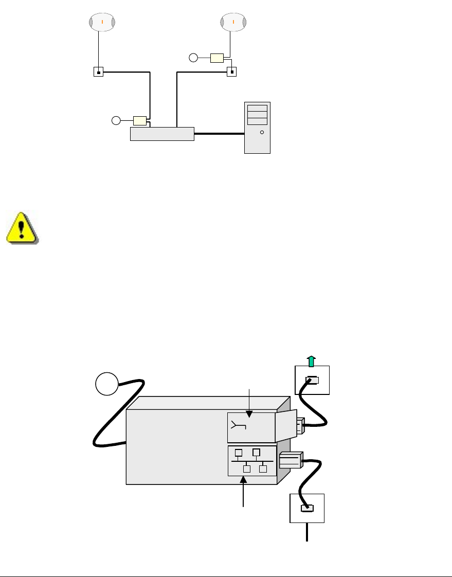
Provision of Power to the nanoBTS
Power for the nanoBTS may be at either the RJ45 outlet or at the output of the last Ethernet
switch/hub/router etc. See Figure 3 below
Ethernet Switch
nanoBTS nanoBTS
BSC
RJ45(48v)
~
~
RJ45
PSU φ
φφ
φ
PSU θ
θθ
θ
θ
θθ
θPSU located at the switch
φ
φφ
φPSU located at nanoBTS
Figure 3 nanoBTS PSU location
Installing the PSU at the Ethernet switch.
If the PSU is located at the patch panel /output port of the Ethernet switch, it is important
that the PSU is connected exactly as illustrated below (failure to do so will cause damage to
the switch). Ensure that the PSU is placed in a location that is ventilated and that the
connection leads provide no safety hazard.
~
PSU
48Vdc
48Vdc
!
110-230Vac
RJ45
Connection to LAN
Connection to nanoBTS
Cable to nanoBTS
Ethernet Switch
Figure 4 PSU location at Switch
IF THE NETWORK HAS AN EXISTING DHCP SERVER DO NOT CONNECT THE
nanoBTS TO THE SWITCH AT THIS TIME.
© ip.access Ltd
COMPANY CONFIDENTIAL 110#010XA_GDE.doc
- 12 -
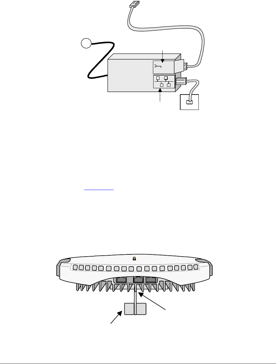
Installing the PSU at the nanoBTS.
Ensure that the PSU is placed in a location that is ventilated and that the connection leads
provide no safety hazard.
RJ45
Connection to LAN
~
PSU
48Vdc
48Vdc
!
110-230Vac
Connection to nanoBTS
Mounting the nanoBTS.
The location of each nanoBTS is shown on the installation floor plan produced at the
network planning stage. The network wiring must be complete before the nanoBTS can
be tested. The nanoBTS should be placed on a wall at or above head height or on a
ceiling.
Note: If the nanoBTS is to be used with an external antenna the nanoBTS should be
modified as shown in appendix 1 before mounting the nanoBTS
a) Fixing to a wall
1) Remove the nanoBTS from the bracket by sliding the removal tool over the central fin
between the bracket and the body of the unit to disengage the locking spring, slide
bracket to separate it from the main body of the unit. The tool may be inserted from
the top or bottom of the nanoBTS
nanoBTS bracket removal tool
Slide tool over
centre vane of
nanoBTS
Figure 5 Separating nanoBTS and mounting bracket
© ip.access Ltd
COMPANY CONFIDENTIAL 110#010XA_GDE.doc
- 13 -
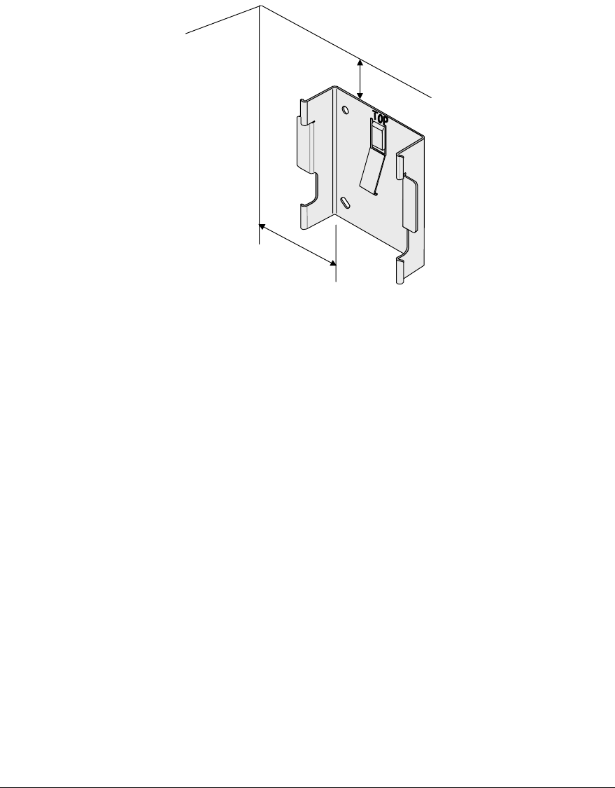
2) Position the bracket on the wall and mark the position of the four screw holes. The top
of the bracket MUST be positioned uppermost. Ensure that the bracket is level and
sufficient clearance is maintained to allow the unit to be located on the bracket (at
least 80mm from the bracket to the top of wall and 120mm from the side of the
bracket to a side wall). See the diagram below.
80mm min
120mm min
Figure 6 Positioning mounting bracket
3) Drill the four holes in the positions marked in step 2 and insert the wall plugs (if
required). Fix the mounting bracket securely to the wall. The bracket is designed to
allow the nanoBTS unit to be mounted with the connections either to the top or bottom
of the unit.
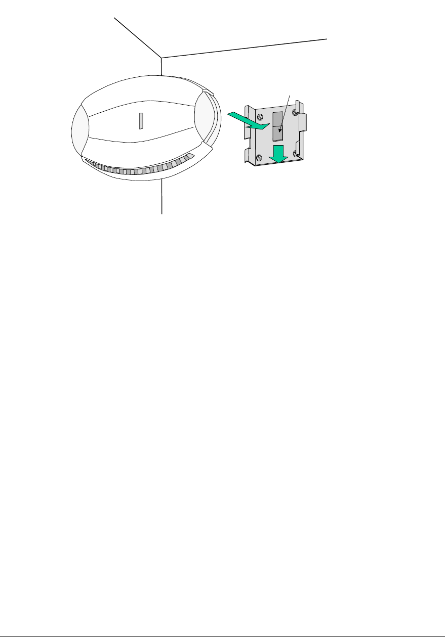
4) Slide the nanoBTS onto the bracket and ensure that the retaining spring engages into
the indent at the rear of the unit.
5) Record the MAC address from the label against the correct location of the nanoBTS
in the site configuration plan.
© ip.access Ltd
COMPANY CONFIDENTIAL 110#010XA_GDE.doc
- 14 -
2
Locking Spring
1
TOP
Figure 7 Mounting the nanoBTS
b) Fixing to a ceiling or a sloping surface
When fixing to a ceiling or a sloping wall the same fixing process and clearances should be
observed as for fixing to a wall (at least 80mm from the bracket to the top of wall and
120mm from the side of the bracket to a side wall). On a sloping surface the top of the
bracket MUST be uppermost. Once the unit has been attached to the bracket the outer
cover MUST be removed to expose the cooling vanes.
Preparation for configuring nanoBTS
Connect the nanoBTS as per figure 3, to either a 48volt wall socket or to the nanoBTS side
of a PSU.
Check the power on self-test sequence by observing the Status Indicator on the nanoBTS.
The normal sequence is described below,
a) Red shows briefly.
b) Orange glows continuously for around 45 seconds as unit boots up.
c) If the boot process is successful the Status Indicator shows orange with a slow
blink (Off – 0.1 seconds. On – 1.9 seconds).
NOTE: Do not connect the nanoBTS to the LAN until the DHCP server is running on the
configuring PC. This is especially important if there is already a DHCP server running on
the LAN
Repeat for all other nanoBTS before proceeding to the configuration.

© ip.access Ltd
COMPANY CONFIDENTIAL 110#010XA_GDE.doc
- 15 -
Configuring the nanoBTS
Step 1. Setting up PC for configuring nanoBTS
Three options exist for commissioning the nanoBTS.
Option 1: Configuring mostly at the site IP switch room
Option 2: Configuring mostly at the BTS. See appendix 3
Option 3: Configuring mostly at the NOC (Network Operations Centre) See
appendix 4
This section covers the steps required to configure the nanoBTS using option 1. The
other options are covered in the appendixes
Check that the following files are loaded onto the laptop PC
C:\ipaccess\Software Releases\”software file name.sdp”
C:\ipaccess\Tools\Windhcpd\windhcpd.exe
C:\ipaccess\Tools\Windhcpd\com.ipaccess.nanoBTS.v1
Using a text editor, open the file C:\ipaccess\windchpd\com.ipaccess.nanoBTS.v1
that has been prepared as part of the system planning process. The file is in the
following format.
# FILENAME: com.ipaccess.nanobts.v1
# Configuration file for windhcpd to server to ip.access nanoBTSs
# NOTE: values in this file override those in dhcpd.conf for nanoBTSs
#
################################################################
########### Basic IP configuration in standard DHCP ###########
################################################################
subnet = 255.255.0.0
router = 172.28.0.254
# The lease time is mandatory for a successful lease
# The value is in seconds. NOTE nanoBTSs assume lease-time=-1 makes the served
# IP and VSI configuration static, and disables future DHCP !!!
lease-time -1
# filename and next-server options tell the nanoBTS to do a TFTP download
# from the next-server (or from this server if omitted) using the given filename
filename = bts-software.sdp
next-server = 172.28.0.1
################################################################
############## VENDOR SPECIFIC INFORMATION (VSI) ##############
################################################################
#
# VSI options for all MAC addresses can be specified here
#omlipaddr = 172.28.0.30
# default omlipport is 3002 for IPA SW BTS builds, may as well has this default.
omlipport = 3002
################################################################
############## MAC SPECIFIC (VSI) ##############
################################################################
# MAC-specific options can be included too - these override the above defaults
# e.g.
# 00:02:95:ff:ff:01 ipaddr=172.28.3.1 lease-time=-1 omlipaddr=172.28.2.42
#
© ip.access Ltd
COMPANY CONFIDENTIAL 110#010XA_GDE.doc
- 16 -
# you can specify any of the following options per MAC address line:
# ipaddr=
# subnet=
# router=
# lease-time=3600
# filename=
# next-server=
# omlipaddr = 172.28.0.30
# omlipport = 3002
# 2ndomlipaddr = 172.28.0.30
# 2ndomlipport = 3006
# location = "On my desk"
# btsid = 42
# trxid = 0
#
# NOTE that MAC addresses are case sensitive and should be in lower case.
00:02:95:00:00:0a ipaddr=172.28.6.10 btsid=1 location=”room 1”
00:02:95:00:00:03 ipaddr=172.28.6.3 btsid=2a location="room 2 west wall"
00:02:95:00:00:04 ipaddr=172.28.6.4 btsid=2b location="room 2 east wall"
00:02:95:00:00:05 ipaddr=172.28.6.5 btsid=3 location=”reception”
Update the file to reflect the settings specified in the site configuration plan. The
DHCP server uses this file, to pass all of the configuration information, including the
IP address to the nanoBTS, and then stores the IP address as a fixed address.
Note: If no software is to be downloaded to the nanoBTS, the [filename] field should
be left blank.
Step 2. Connecting the nanoBTS
Connect all the RJ45s to the switch.
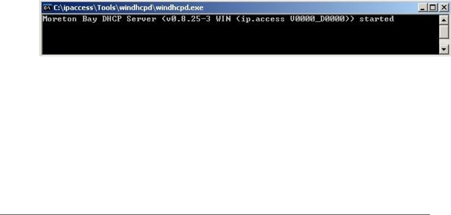
Start the DHCP server and the TFTP server by running
C:\ipaccess\tools\windhcpd\windhcpd.exe (or use the desktop icon). The following
screens are displayed when the servers are running and no further intervention is
required, as the servers will automatically respond to requests from the nanoBTS.
Figure 8 DHCPD server
© ip.access Ltd
COMPANY CONFIDENTIAL 110#010XA_GDE.doc
- 17 -
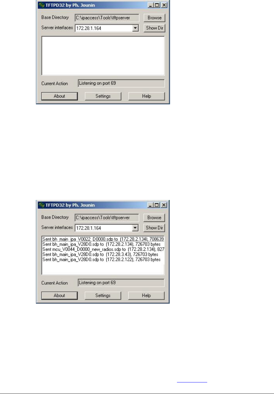
Figure 9 TFTP server
Step 3. Setting IP addresses and downloading software
The DHCP server automatically responds to the nanoBTS broadcast with the relevant
IP configuration.
If a .sdp filename has been specified in the “com.ipaccess.nanoBTS.v1”
configuration file, then the software will download from the TFTP server to the
nanoBTS. Check against the IP address in the TFTP server window that the .sdp file
has been downloaded and that no error / fail message is displayed.
Figure 10 TFTP server window when active
Setting the frequency of nanoBTS oscillator
The frequency of the nanoBTS is referenced to a crystal oscillator that has to be
accurately calibrated to 26MHz ± 20ppb. The frequency can be adjusted using either of
two methods:
a) Calibration by synchronisation to other GSM base stations transmitting locally. This is
the preferred method, as described below.
b) Using a frequency counter and manually adjusting the frequency. This is an alternative
method that can be used at the BTS site as described in Appendix 2)
© ip.access Ltd
COMPANY CONFIDENTIAL 110#010XA_GDE.doc
- 18 -
Note: The following steps 4, 5, 6 and 7 should be done on one nanoBTS and then repeated on
each remaining nanoBTS in turn.
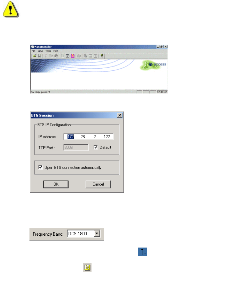
Step 4. Calibration of nanoBTS using frequency synchronisation
Start the nanoInstaller and open a session to the nanoBTS by entering the IP address of
the nanoBTS for which the calibration is to be performed.
Figure 11 nanoInstaller opening screen
Figure 12 BTS Session
Wait until the mode and BTS status boxes indicate idle.
Once the connection is established, select the frequency band from the tool
bar.
Select, on the, Frequency Synchronisation Test icon .
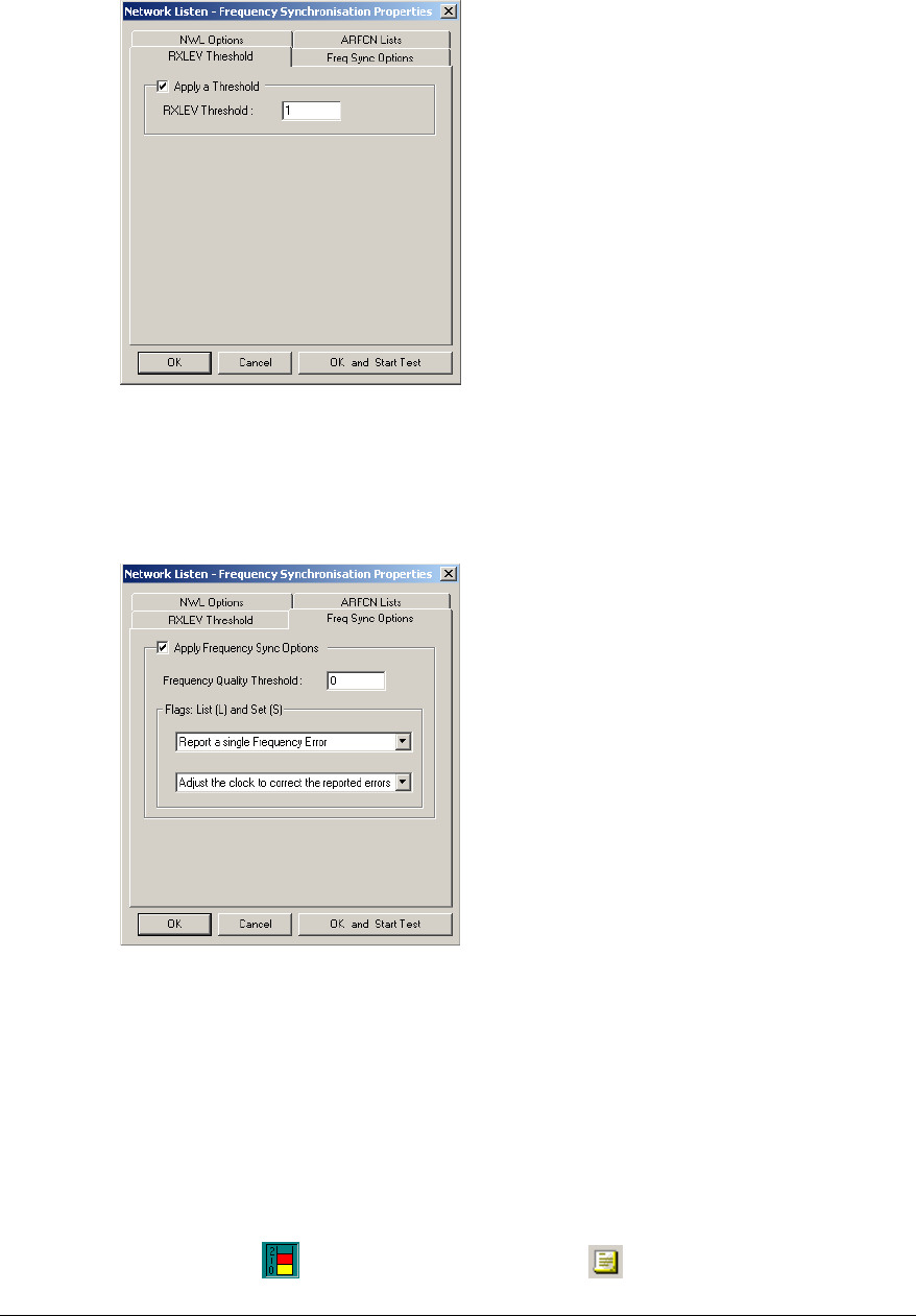
Select the NWL Properties ( ) icon and then select the ARFCN Lists tab and check
that no lists are selected.
Select the RXLEV Threshold tab and set (tick) “Apply a Threshold”.
Set the threshold to 1 to ensure a sufficiently strong signal is used for calibration.
Note: Prior to calibration, the unit must be powered up for a minimum of 60
minutes, to ensure frequency stability.
© ip.access Ltd
COMPANY CONFIDENTIAL 110#010XA_GDE.doc
- 19 -
Figure 13 RXLEV Threshold
Select the Freq Sync Options tab and apply Frequency Sync Options.
Set drop menus to: “Report a single frequency error” and “Adjust the clock to correct the
reported errors”
Figure 14 Freq Sync Options
Click “OK and Start Test” button. Perform Test ACK is reported in the message pane.
On completion of the test, the average frequency error following adjustment will be
displayed.
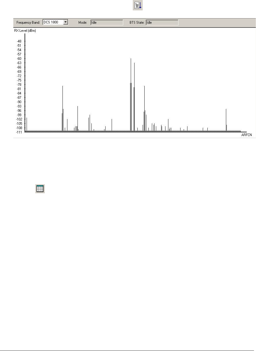
Step 5. Check macro network channel usage
This test is designed to check for possible interferers with the nanoBTS
Click Channel Usage icon followed by the properties ( ) icon and then select the
ARFCN Lists tab and check that no lists are selected.
© ip.access Ltd
COMPANY CONFIDENTIAL 110#010XA_GDE.doc
- 20 -
The RXLEV threshold should not be applied.
Click OK and start test or select NWL Start ( ) from the menu bar.
Figure 15 NWL Test Results
At the end of the test the bar chart shows the received level of signals, as shown in
Figure 15.
The received levels can also be seen in a list view by clicking on the “List View” Icon
().
The maximum acceptable level for any interference is -95dBm and any signal above
this and on a channel close to that planned for the nanoBTS should be investigated.
Export results to file by selecting ‘File’ ‘Export To File’ and save the file as the default
file name, which will be a combination of the units IP address and the test name to a
pre-determined directory.
© ip.access Ltd
COMPANY CONFIDENTIAL 110#010XA_GDE.doc
- 21 -
Step 6. BCCH Channel Usage Test
This test is designed to identify GSM BCCH signals, which can be interrogated later during
the BCCH Information Test.
Select BCCH Channel Usage icon .
Select the Properties ( ) icon and then select the ARFCN Lists tab and check that
the Apply a White List and Apply a Black List boxes are unchecked.
Click OK and start test or select BCCH Channel Usage Test Start ( ) from the
menu bar. Wait for the test to complete.
Step 7. Retrieve BCCH frequency information
This test measures the receive levels from neighbouring cells in order that the network
operator can effectively plan for handovers. Within the building the handovers will be
designed to pass to other nanoBTS but from the entrance of the building handovers may
be passed to the macro network as the caller moves away from the building.
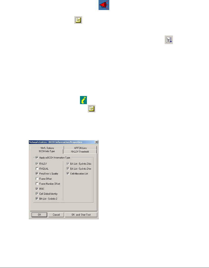
Select BCCH Information icon and open the Network Listen BCCH information
screen, using the Properties ( ) icon. Select the RXLEV Threshold tab and set
threshold to 1.
Select the BCCH Info Type tab and check the boxes as shown below.
Click OK and Start test.
Figure 16 BCCH Information Properties
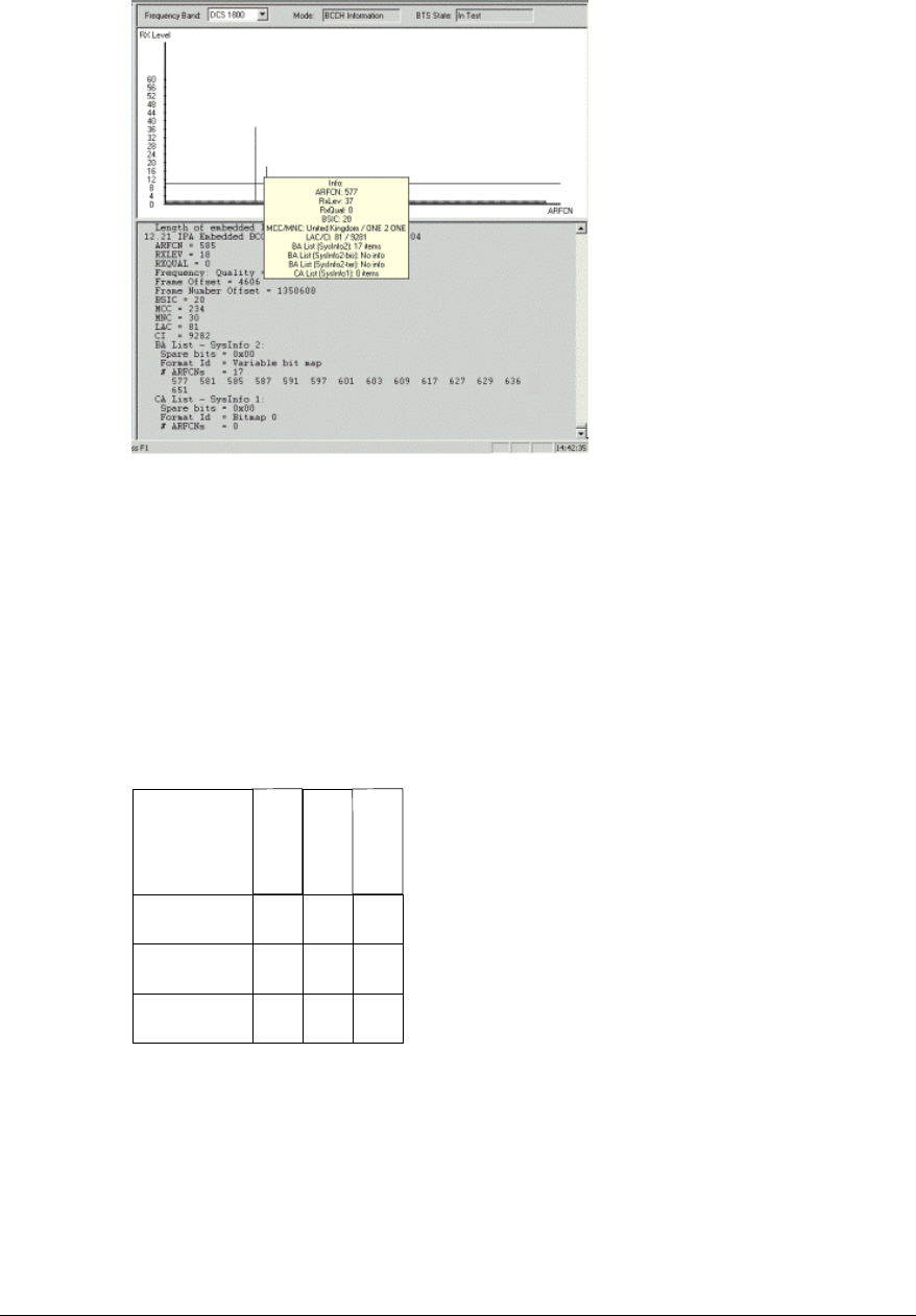
Frequencies selected as a result of the channel usage test are plotted. Placing the
cursor over the frequency plot displays 'Info' summary.
When the test has completed, export the results to a file by selecting ‘File’ ‘Export To
File’ and save the file as the default file name, which will be a combination of the units
IP address and the test name, in a pre-determined directory.
© ip.access Ltd
COMPANY CONFIDENTIAL 110#010XA_GDE.doc
- 22 -
Figure 17 BCCH Information Test Results
Repeat tests 4, 5, 6 and 7 for each nanoBTS.
Step 8. Measuring path loss between nanoBTS
This test is designed to measure path loss between pairs of BTS sites so that the TX
power can be adjusted to achieve required coverage (typically 95%).
In this step each nanoBTS is selected in turn to transmit and the signal is measured on all
other nanoBTS in the building. The information from each test will be entered into a matrix
on the installation report, as shown below.
nTRX a
nTRX b
nTRX c
X
X
X
nTRX a
nTRX b
nTRX c
Extend matrix to
cover all nanoTRX
Record path loss
for each
basestation pair
Table 1 Path Loss Matrix
If a connection is not already established to each nanoBTS, in the installation, open a
BTS session by selecting File, OpenBTS session (or Ctrl +O).
Enter the IP address of a nanoBTS and click OK
© ip.access Ltd
COMPANY CONFIDENTIAL 110#010XA_GDE.doc
- 23 -
Figure 18 BTS Session
Select the window for the nanoBTS to be used as the beacon
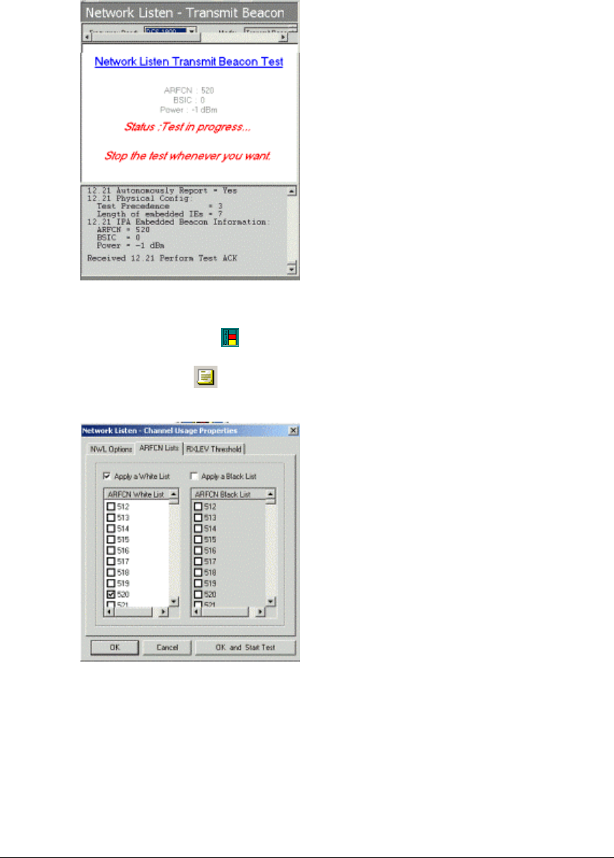
Select Transmit Beacon from the side menu (when set as a beacon the cell is active
but barred).
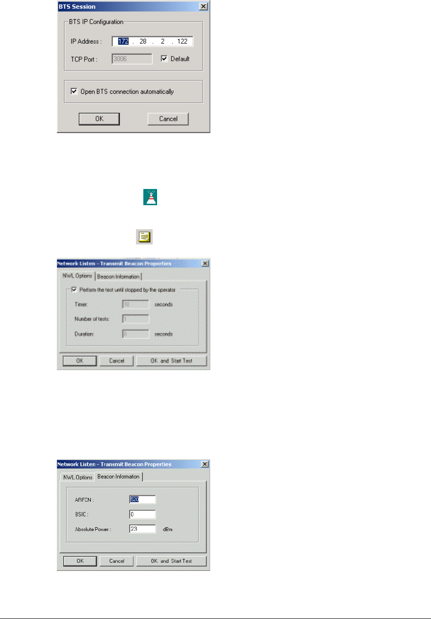
Click NWL Properties ( ) and check the Perform the tests until stopped box
Figure 19 Transmit Beacon Properties: NWL options
On the Beacon Information tab and enter one ARFCN from the site configuration plan.
Set the BSIC (Base Station Identity Code) from the site configuration plan and
Set the Absolute Power to the maximum power allowed, specified in the site configuration
plan.
Figure 20 Transmit Beacon Properties: Beacon Information
Click the OK and Start Test button
© ip.access Ltd
COMPANY CONFIDENTIAL 110#010XA_GDE.doc
- 24 -
Figure 21 NWL Transmit Beacon
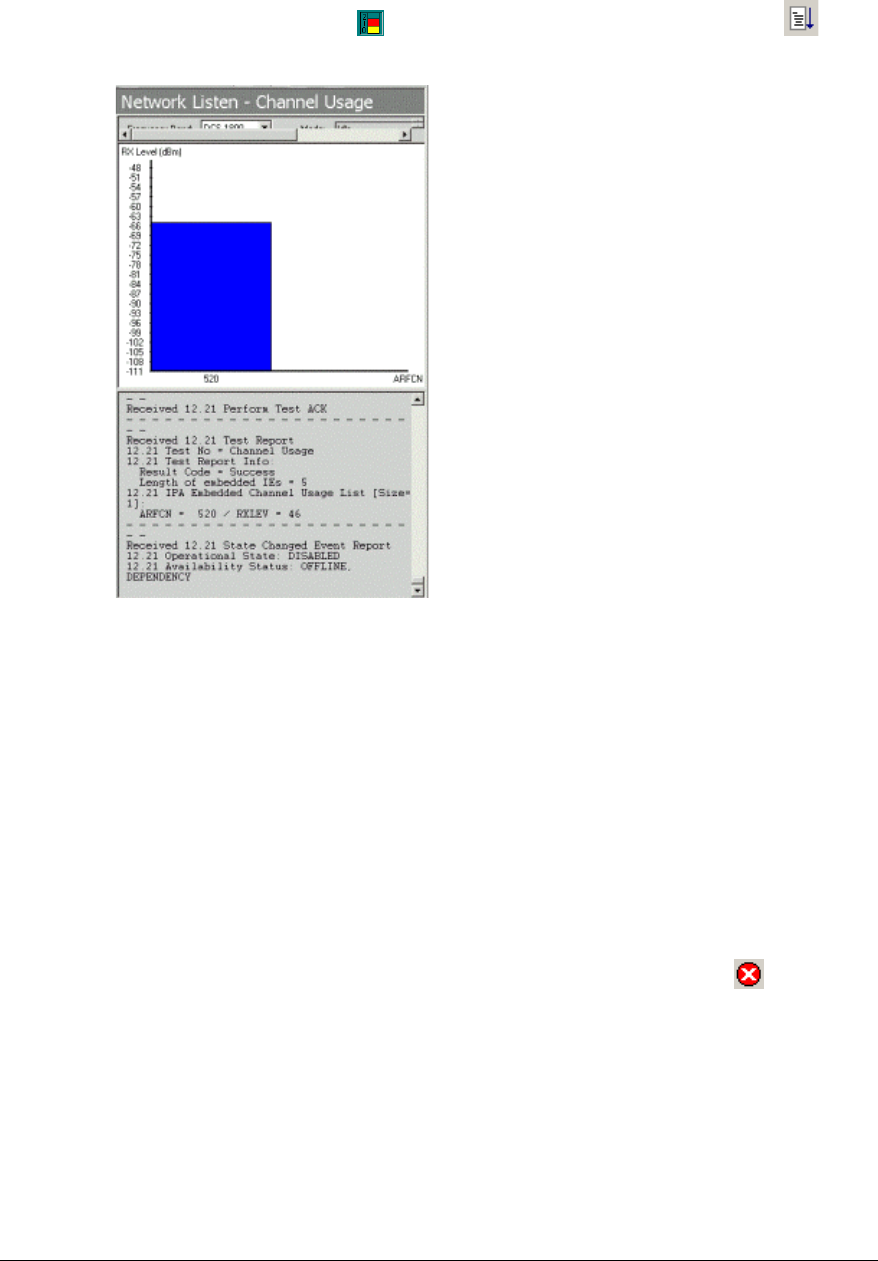
Select the Channel Usage ( ) icon from the side menu.
Click NWL Properties ( ) and select the ARFCN list tab and select the channel being
used by the beacon from the white list (only one should be set).
Figure 22 NWL Channel Usage Properties
Click OK
For each nanoBTS, except the one that is determined to be the beacon;
© ip.access Ltd
COMPANY CONFIDENTIAL 110#010XA_GDE.doc
- 25 -
Select the Channel Usage ( ) icon from the side menu and then Test Start ( )
from the main menu bar.
Figure 23 NWL Channel Usage measurement
From the displayed bar chart note the reading. In the example above the value shown
is –65dbm
Calculate the path loss by subtracting the RX level from the TX level
i.e. [=23dBm TX] – [-65dBm RX] = 88dB path loss.
Record the path losses in the path loss matrix spreadsheet contained within the
installation report.
Calculate and record the transmit power level for each nanoBTS so that the received
power level, detected by at least two neighbouring BTS shall typically be -85dBm and
will be specified in the "Site Configuration Plan"
Select the window for the beacon nanoBTS, and click on the NWL stop ( ) icon.
Repeat the test for each nanoBTS in turn; by setting each into transmit beacon test
and measuring the path loss between it and each other nanoBTS to complete the
matrix.

© ip.access Ltd
COMPANY CONFIDENTIAL 110#010XA_GDE.doc
- 26 -
Step 9. Walk Test
This test is performed to fine adjust the nanoBTS(s) as agreed to give a suitable service
meeting the coverage levels specified in the site configuration plan.
Set each nanoBTS into beacon test mode on its allocated ARFCN and power level as
calculated in the previous step. (See Step 8)
Using a test mobile or other GSM measuring device, walk through the installation site
looking for areas where service is below the threshold specified in the site
configuration plan, recording black spots.
Individual BTS power levels may be adjusted to minimise areas of poor network
performance.
Record all locations that are subject to poor reception.
Step 10. Installation Report
Compile an installation report for the network operator to enable them to set their BTS
neighbours, cell list, power levels and handover thresholds to optimise the network.
The report should contain: -
• BCCH information
• Channel usage
• Path loss matrix
• Walk test results
• Completed site configuration plan
This completes the installation and configuration of the nanoBTS site.

© ip.access Ltd
COMPANY CONFIDENTIAL 110#010XA_GDE.doc
- 27 -
Regulatory Compliance
The nanoBTS conforms to the following regulatory standards.
Type Approvals
• FCC Rule 47 Parts 2, 15, 24
Safety Certifications
• UL 60950 3rd Edition
NOTE: Changes or modifications not expressly approved by the party responsible for compliance
may void the user's authority to operate this equipment.
© ip.access Ltd
COMPANY CONFIDENTIAL 110#010XA_GDE.doc
- 28 -
Appendix 1: Modifying nanoBTS for use with external antenna
Remove Plastic cover.
Remove the top and bottom plates from both ends of the nanoBTS. Lever gently apart with
screwdriver in notch.
Antenna Cover
Top
Antenna Cover
Bottom
Notch to aid
removal of
cover
Antenna Cover
Body
Figure 24 Removal of antenna covers
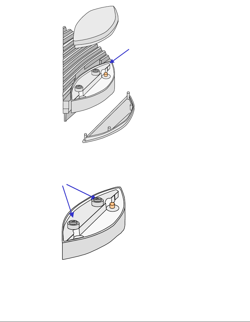
Remove the antenna cover body, by unscrewing the two Torx T20 screws retaining
Remove Torx Screws
Figure 25 Removal of antenna cover body
Fit the replacement antenna cover body ensuring that the feeder cable connector fits into
the antenna. Note that one cover only fits the receiver whilst the other fits the transmitter.
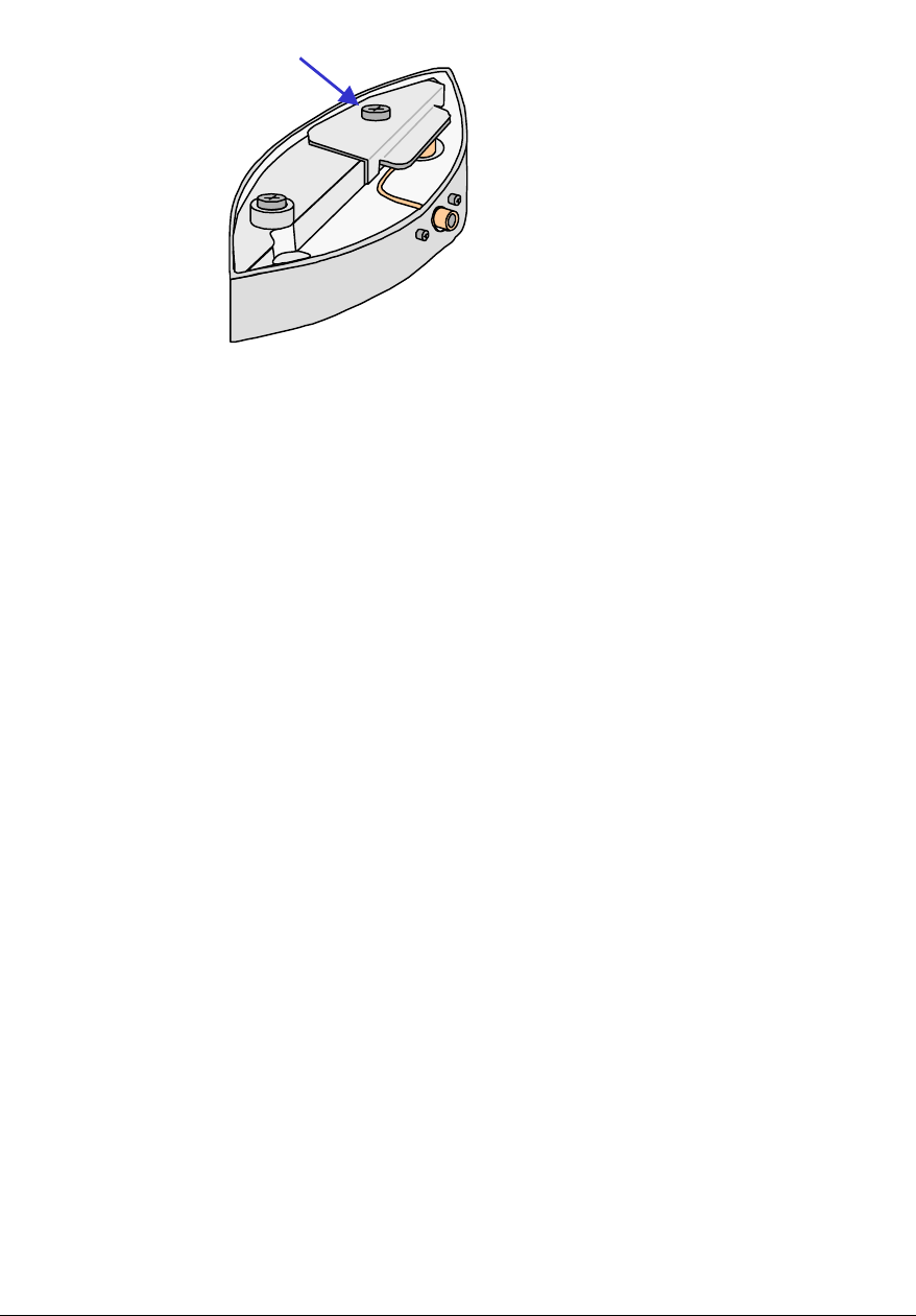
Fit the clamp as shown below and second Torx screw, then replace top and bottom covers.
© ip.access Ltd
COMPANY CONFIDENTIAL 110#010XA_GDE.doc
- 29 -
Clamp plate
Figure 26 Fit clamp plate
Repeat the process for the other end of nanoBTS
© ip.access Ltd
COMPANY CONFIDENTIAL 110#010XA_GDE.doc
- 30 -
Appendix 2: Alternative method to set frequency of nanoBTS
oscillator
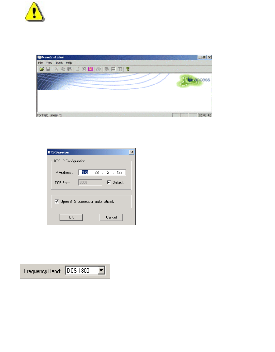
Start the nanoInstaller. Select from menu File, Open BTS Session
Figure 27 NanoInstaller Opening Screen
Enter the IP address of the nanoBTS that is to be calibrated.
Figure 28 BTS Session
Click OK and wait until the Mode and BTS State boxes indicate idle.
Once the connection is established, select the frequency band from the tool bar.
Note: The nanoBTS should be powered on for at least 60 minutes before
performing the frequency calibration procedure, in order to allow the oscillator to
reach its normal operating temperature
© ip.access Ltd
COMPANY CONFIDENTIAL 110#010XA_GDE.doc
- 31 -
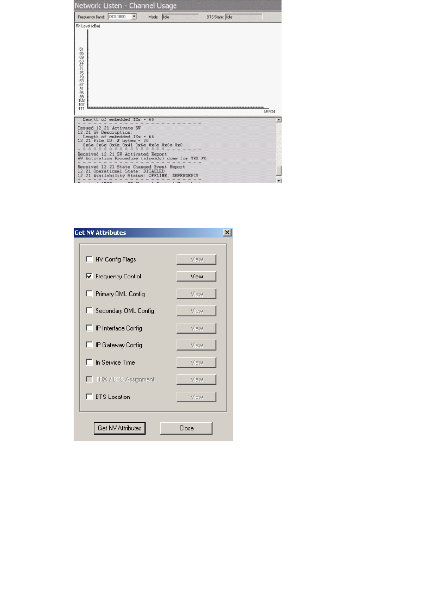
Figure 29 nanoInstaller after connection to the nanoBTS
From the menu select Tools/ Get NV attributes and check the Frequency Control box.
Figure 30 Get NV Attributes
Click the Get NV Attributes button. When View button alongside is enabled, click on it and
the value will be displayed.
© ip.access Ltd
COMPANY CONFIDENTIAL 110#010XA_GDE.doc
- 32 -
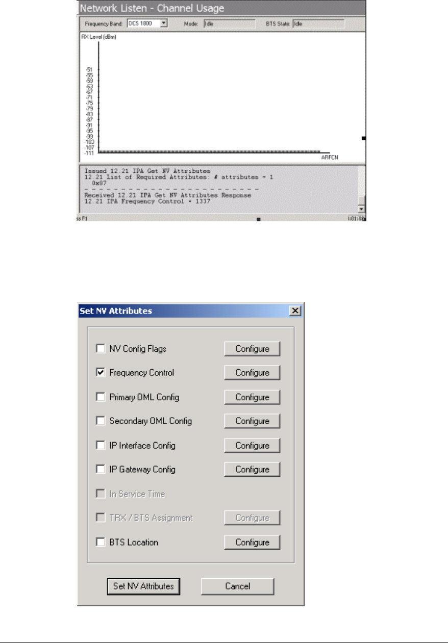
From the menu select Tools/ Set NV attributes and check the Frequency Control box.
Connect a frequency counter to the TIB out port on the nanoBTS
Figure 31 Set NV Attributes
© ip.access Ltd
COMPANY CONFIDENTIAL 110#010XA_GDE.doc
- 33 -
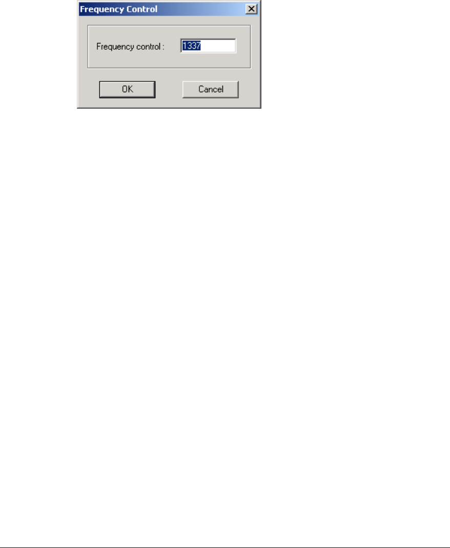
Click the Set NV Attributes button.
Click the configure button alongside frequency control and adjust the frequency control
value until the measured frequency is 26MHz± 20ppb.
Adjustment of the 26MHz is typically in the order of 1.5Hz per 100 DAC steps.
Figure 32 Frequency Control
© ip.access Ltd
COMPANY CONFIDENTIAL 110#010XA_GDE.doc
- 34 -
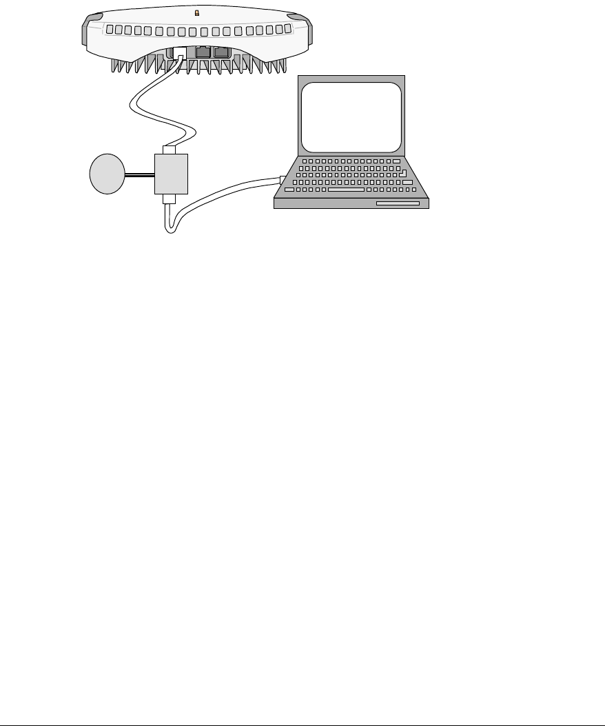
Appendix 3: Commissioning at the nanoBTS
If commissioning is to be done mostly at the nanoBTS instead of connecting the PC to
LAN in switch room (step 2) the laptop PC should be set up at the nanoBTS as shown the
diagram below using the power over Ethernet adapter to connect the PC onto the LAN
(the adapter applies the 48V DC to the nanoBTS). Connect a crossed RJ45 lead from the
adapter to the Ethernet connector on the nanoBTS.
Power Over
Ethernet
Adapter
nanoTRX
nano Installer
Laptop PC equipped with
nano Installer, Windhcpd
and TFTP software
~
Figure 33 Test Setup, Option 1
Page
Step 1. Setting up PC for configuring nanoBTS ..................................................................15
Steps 2 to 7 performed at the nanoBTS
Step 2. Connecting the nanoBTS........................................................................................16
Step 3. Setting IP address and downloading operational software .....................................17
Step 4. Calibration of nanoBTS using frequency synchronisation.......................................18
Step 5. Check macro network channel usage.....................................................................19
Step 6. BCCH Channel Usage Test ....................................................................................21
Step 7. Retrieve BCCH frequency information....................................................................21
Disconnect installation PC and connect to RJ45 Ethernet
Step 8 performed at the BSC / Switch room
Step 8. Measuring path loss between nanoBTS .................................................................22
Steps 9 and 10 performed in building
Step 9. Walk Test................................................................................................................26
Step 10. Installation Report ...................................................................................................26
nanoBTS

© ip.access Ltd
COMPANY CONFIDENTIAL 110#010XA_GDE.doc
- 35 -
Appendix 4: Commissioning mostly at the NOC
Steps 1 to 3 performed at the nanoBTS Page
Step 1. Setting up PC for configuring nanoBTS ..................................................................15
Step 2. Connecting the nanoBTS........................................................................................16
Step 3. Setting IP address and downloading operational software .....................................17
Steps 4 to 8 performed at the NOC
Step 4. Calibration of nanoBTS using frequency synchronisation.......................................18
Step 5. Check macro network channel usage.....................................................................19
Step 6. BCCH Channel Usage Test ....................................................................................21
Step 7. Retrieve BCCH frequency information.................................................................. 21
Step 8. Measuring path loss between nanoBTS .................................................................22
Steps 9 and 10 performed in building
Step 9. Walk Test................................................................................................................26
Step 10. Installation Report ...................................................................................................26
© ip.access Ltd
COMPANY CONFIDENTIAL 110#010XA_GDE.doc
- 36 -
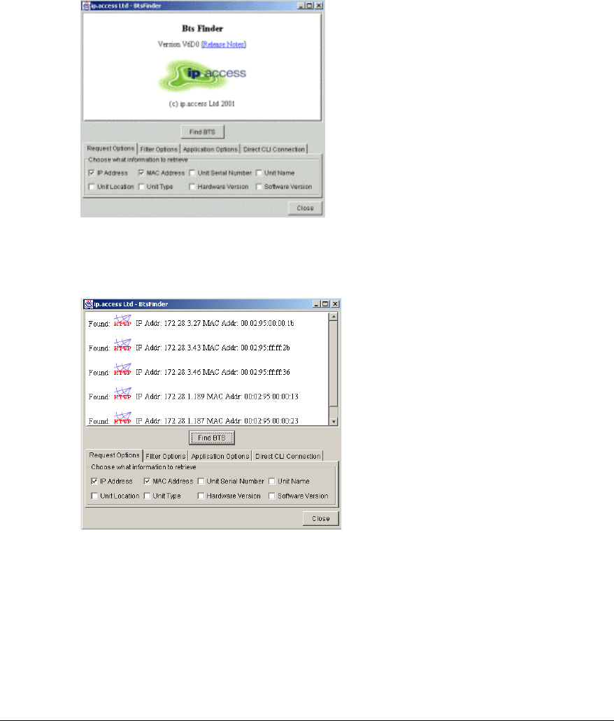
Appendix 5 Troubleshooting
Checking that the nanoBTS has successfully downloaded an IP
address
Start the program 'Bts Finder' select the IP address and MAC address boxes and
click the Find BTS button.
Figure 34 Bts Finder Opening Screen
Check that the IP address and MAC address are as required.
Figure 35 Find BTS Results
Resetting the nanoBTS to factory default settings.
1. Remove the connecting cable providing power to the nanoBTS.
2. Insert the dongle into the "TIB IN" port.
3. Power ON the unit by reconnecting the Ethernet cable to the nanoBTS.
4. Wait until the LED shows fast blinking red (0.3 seconds on and 0.1 seconds off)
5. Remove the dongle.
6. Reboot the unit by removing the Ethernet power cable, waiting 10 seconds and then
reconnect the Ethernet cable.

© ip.access Ltd
COMPANY CONFIDENTIAL 110#010XA_GDE.doc
- 37 -
Communication Problems
No LEDs
Check that the BTS is connected to the Ethernet cable
and ensure it is plugged in fully into the Ethernet
socket.
Check that the Ethernet cable is plugged into a power
supply.
Check that the Ethernet is plugged into the correct
socket on the power supply (BTS).
LED’s have been disabled using nanoInstaller
Does the BTS have Power?
Check that the power supply is connected to the
mains and powered up.
LED is on but is flashing orange (1sec on, 1sec off)
Check the Ethernet cable between power supply unit
and installation PC.
Check that the cable between PC and Power supply
unit is crossed, if connecting directly to the nanoBTS
Check that the Ethernet is connected to a correct
(Live) socket on the hub.
The unit is powered up but
does it have proper
connection to the installation
PC.
Check that the DHCP server is running on installation
PC
No communication between the nanoInstaller and the BTS
Check that nanoInstaller is not set to look at the wrong
IP address or port number
Check that the Ethernet cable is connected between
the installation PC and the BTS via the power supply
box.

© ip.access Ltd
COMPANY CONFIDENTIAL 110#010XA_GDE.doc
- 38 -
Clock Adjustment Problems
No 26MHz clock during Frequency adjustment
Clock adjustment cable not plugged into TIB-OUT
socket on BTS.
Unsettled 26MHz during frequency adjustment
Has the BTS been powered up long enough to warm
up? Warm up time is normally less than 60 minutes
but can sometimes take over one hour if the unit has
been stored in a cold environment before power up.
Problems During Beacon Test
No signal seen on other nanoBTS during beacon test
The nanoBTS is not enabled to transmit a beacon
The power level of the beacon BTs is set too low.
Select a higher power level.
A white list has been applied which does not include
the beacon channel
If using the external antenna, ensure that the cable
connections are in place.

© ip.access Ltd
COMPANY CONFIDENTIAL 110#010XA_GDE.doc
- 39 -
Glossary of Terms and Abbreviations
10 Base-T Basic Ethernet at 10 Mbit/sec
100 Base-T Ethernet running at 100 Mbit/sec
ACH Access Channel
ACK Acknowledgement signal
ARFCN Absolute Radio Frequency Channel Number
BCCH Broadcast Control Channel
BCH Broadcast Channel. A channel transmitted by one (e.g. BS) and received by
many (e.g. MS)
BER Bit Error Rate
BSC Base Station Controller. The 'brains' of a base station subsystem, controlling the
radio equipment in the BTS
BSS Base Station Subsystem (includes BTS and BSC)
BTS Base Transceiver System (radio portion of BS)
dB Decibel. 10 times the logarithm of the value in base 10
dBm Decibels referenced to one milliwatt
DHCP Dynamic Host Control Protocol. Allows automatic assignment of IP addresses on
a network
DL Downlink. Radio link from network 'down' to the terminal. Compare with UL
Ethernet Ȁ
ȀȀ
ȀA LAN protocol using collision detection to resolve access contentionȀ
ETSI European Telecommunications Specification Institute
FTP Ȁ
ȀȀ
ȀFile Transfer ProtocolȀ
Gateway MSC Ȁ
ȀȀ
ȀA MSC designed to receive wireless calls from the PSTNȀ
GSM Ȁ
ȀȀ
ȀGlobal System for Mobile CommunicationsȀ
Handoff Ȁ
ȀȀ
ȀThe process of a MS changing from one frequency in one cell or sector to a
different frequency in a neighbouring cell or sectorȀ
IP Internet Protocol
kbps Kilobits per second
LAN Local Area Network
LED Light Emitting Diode
MAC Medium Access Control (layer in a protocol stack)
MS Mobile Station (wireless phone)
MSC Mobile Switching Centre
NAK Negative Acknowledgement signal
nanoBSC ip.access term for a base station controller
nanoBTS ip.access term for a picocellular basestation
NL Neighbour List
NOC Network Operations Centre
NWL Network Listen Ip.access term for functionality of monitoring surrounding
basestations from the nanoBTS
OCXO Oven Controlled Crystal Oscillator
OMC Operations and Maintenance Centre
PC Personal Computer
PLMN Public Land Mobile Network. A cellular or PCS network
Protocol A specification of the messages used to communicate over one or more
interfaces
PS Packet Switched
PSTN Public Switched Telephone Network
QoS Quality of Service. A list of measurable attributes such as bandwidth, delay and
jitter that should be met for a customer
RF Radio Frequency

© ip.access Ltd
COMPANY CONFIDENTIAL 110#010XA_GDE.doc
- 40 -
RJ45 Minature 8-position keyed data jack, providing electrical network connection for
data
RX Receiver
.sdp Software download packages
SysInfo System Information
TCP Transmission Control Protocol. A protocol that provides for reliable delivery of
messages over the Internet. See IP
TCP/IP TCP used over IP
TFTP Trivial File Transfer Protocol
TRX Transceiver
TX Transmit
UL Uplink. Radio link in the direction ‘up’ to network. Compare with DL
VoIP Voice over IP