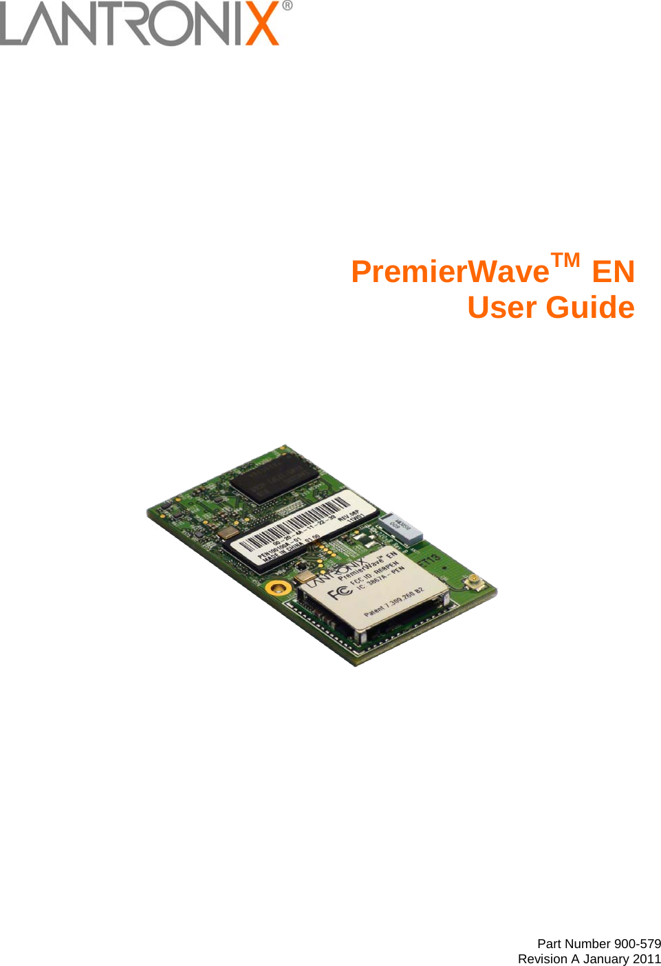
lantronix PEN PremierWave EN Wireless Device Server User Manual PremierWave EN User Guide
lantronix PremierWave EN Wireless Device Server PremierWave EN User Guide
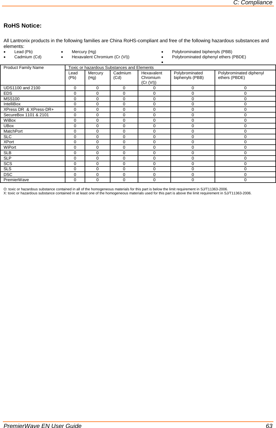
UserManual.wiki
>
lantronix
>
PEN User Manual
Manual
Navigation menu
Upload a User Manual
Namespaces
Wiki Guide
HTML
PDF
Info
Views
User Manual
Discussion / Help
Navigation
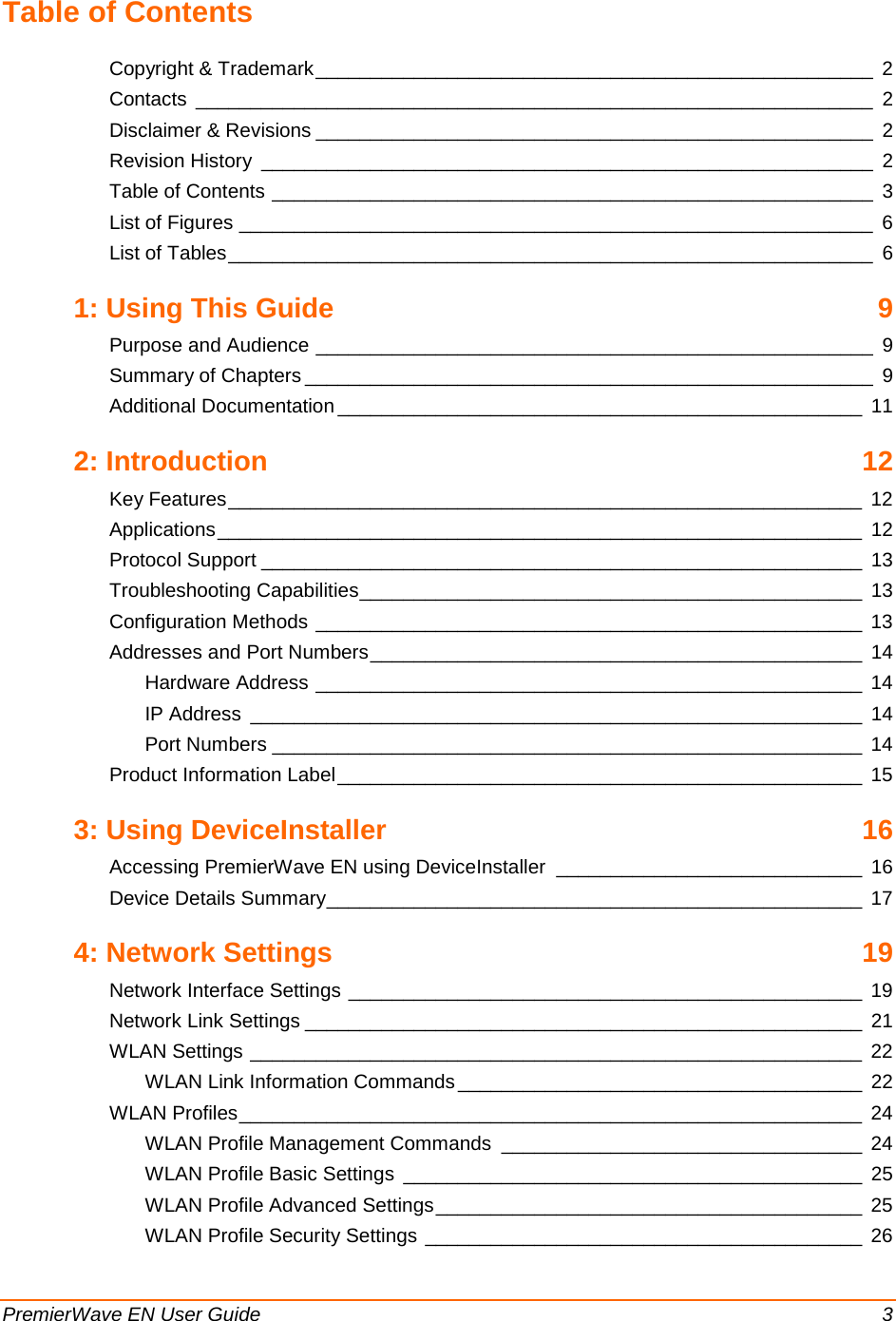
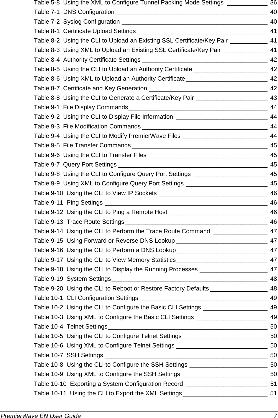

![PremierWave EN User Guide 12 2: Introduction The PremierWave EN embedded Ethernet Device Server is a complete network-enabling solution in a 30 (1.181) X 55 (2.165) X 6.45 (0.248) package. This miniature device server empowers original equipment manufacturers (OEMs) to go to market quickly and easily with Ethernet and/or wireless networking and web page serving capabilities built into their products. [DIMS = mm (in.)] Key Features Power Supply: Regulated 3.3V input required. There is a step-down converter to 1.5 volts for the processor core and 1.8 volts for the memory subsystem. All voltages have LC filtering to minimize noises and emissions. Controller: 32-bit ARM9 microprocessor running at 400 MHz with 32kB Data Cache and 32 kB Instruction Cache Memory: Up to 64 MB SDRAM and 256 MB NAND Flash (Default 64 MB each). Up to 16 MB serial SPI Flash (Default 8 MB). Ethernet: 10/100 Mbps Ethernet transceiver. Wireless: Dual Band 802.11 a/b/g/n with an on-board antenna and option for external antennas and diversity. Serial Ports: Two high speed RS232/RS422/RS485 serial ports with all hardware handshaking signals. Baud rate is software selectable (300 bps to 921600 bps). One emulated serial port on the USB Device Port (up to Full Speed 12 Mbps), using standard CDC-ACM protocol. Two USB 2.0 Full Speed (12 Mbps) Host ports USB 2.0 Full Speed (12 Mbps) Device port Master/Slave high speed SPI interface I2C interface Configurable I/O Pins (CPs): Up to nine pins are configurable as general purpose I/Os if no DTR or DCD is used on serial ports. Not 5V tolerant. Interface Signals: 3.3V-level interface signals. Temperature Range: Operates over an extended temperature range of -40°C to +85°C. Applications The PremierWave EN device server connects serial devices such as those listed below to Ethernet networks using the IP protocol family. ATM machines CNC controllers Data collection devices Universal Power Supply (UPS) management unit Telecommunications equipment](https://usermanual.wiki/lantronix/PEN/User-Guide-1524692-Page-12.png)
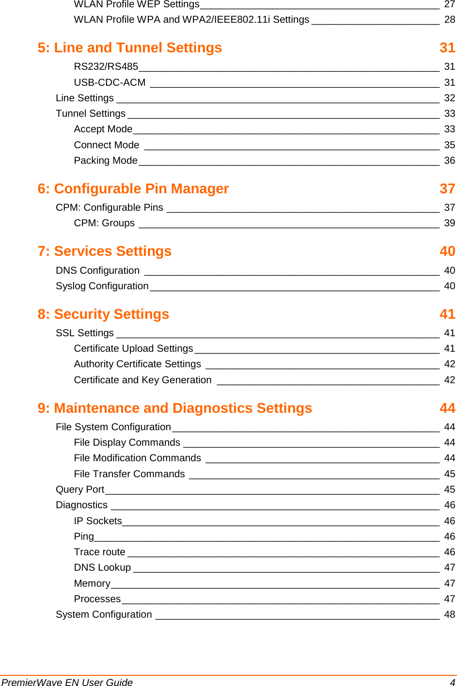
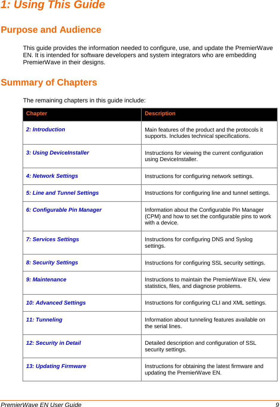
![6: Configurable Pin Manager PremierWave EN User Guide 39 CPM: Groups The CP Groups page allows for the management of CP groups. Groups can be created or deleted. CPs can be added to or removed from groups. A group, based on its state, can trigger outside events (such as sending email messages). Only an enabled group can be a trigger. Group name State CP info test1 Enabled 1 CPs assigned test2 Enabled 1 CPs assigned CPM – Groups Current Configuration Description Group Name Shows the CP group’s name. State Indicates whether the group is enabled or disabled. CP Info Provides CP group information. CPM – Groups Group Status Description Name Shows the CP Group name. State Current enable state of the CP group. Value Shows the CP group’s current value. Bit Visual display of the 7 bit placeholders for a CP. Level A “+” symbol indicates the CP’s bit position is asserted (the voltage is high). A “-“ indicates the CP voltage is low. I/O Indicates the current status of the pin: I = input O = output <blank> = unassigned Logic An “I” indicates the CP output is inverted. Binary Shows the assertion value of the corresponding bit. X = group is disabled or bit is unassigned in group CP# Shows the configurable pin number and its bit position in the CP group. Action Command To create a CP group create <group> To delete a CP group delete <group> To enable or disable a CP group enable / disable <group> To set a CP group’s value set <group> <value> To add a CP to a CP group add <cp> to <group> To delete a CP from a CP group delete <cp> from <group> To change CP to input or output set <cp> as [output | input] To change CP to an output value set <cp> as output assert low](https://usermanual.wiki/lantronix/PEN/User-Guide-1524692-Page-39.png)


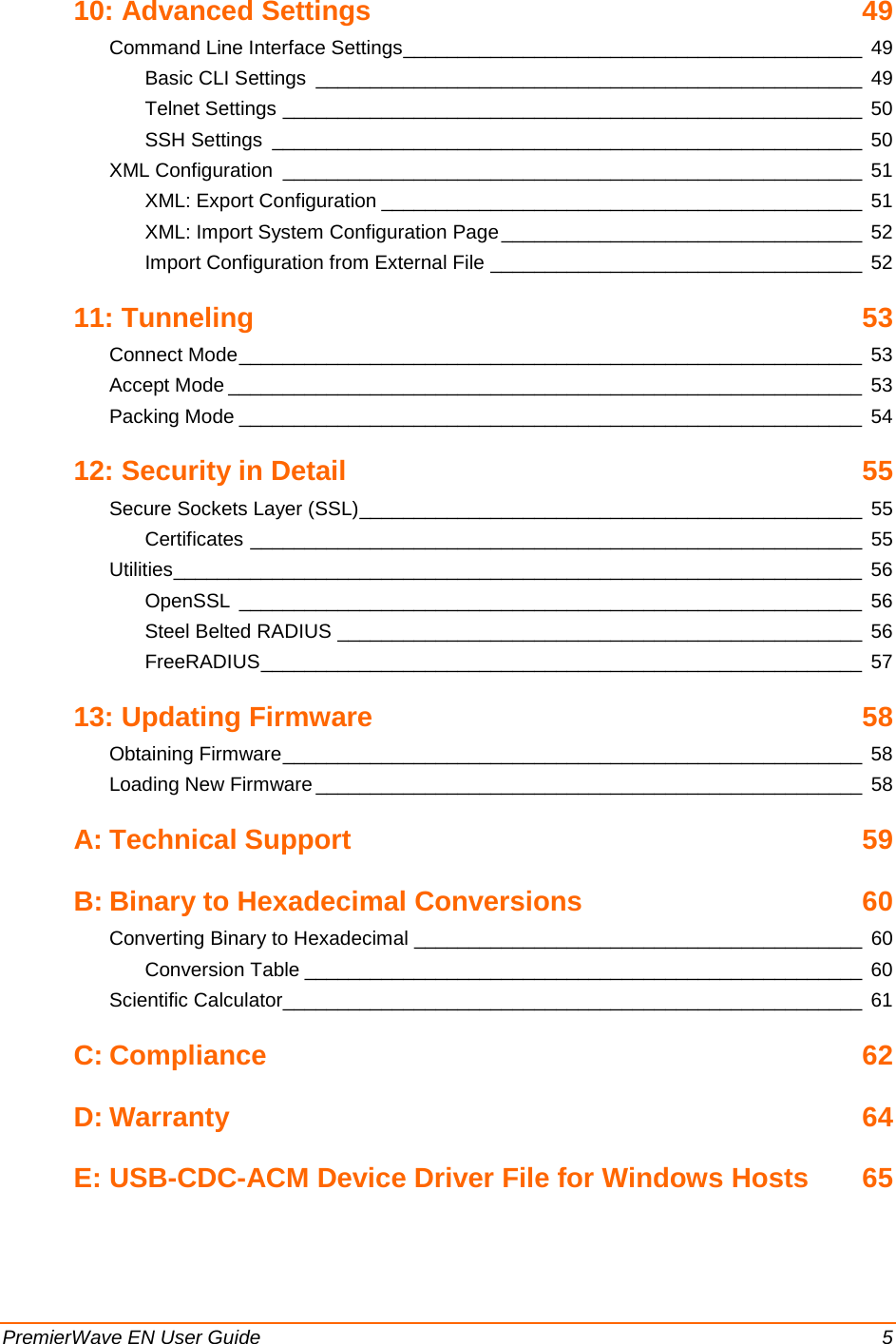
![PremierWave EN User Guide 65 EE:: UUSSBB--CCDDCC--AACCMM DDeevviiccee DDrriivveerr FFiillee ffoorr WWiinnddoowwss HHoossttss The following file may be used to enable Windows to recognize the USB-CDC-ACM connection to the PremierWave EN's USB Device port. This file is copied verbatim from the Linux distribution (2.6.36+) at Documentation/usb/linux-cdc-acm.inf. Place this file on the Windows host somewhere. When Windows prompts for a device driver for the USB connection, point it to this file. ; Windows USB CDC ACM Setup File ; Based on INF template which was: ; Copyright (c) 2000 Microsoft Corporation ; Copyright (c) 2007 Microchip Technology Inc. ; likely to be covered by the MLPL as found at: ; <http://msdn.microsoft.com/en-us/cc300389.aspx#MLPL>. ; For use only on Windows operating systems. [Version] Signature="$Windows NT$" Class=Ports ClassGuid={4D36E978-E325-11CE-BFC1-08002BE10318} Provider=%Linux% DriverVer=11/15/2007,5.1.2600.0 [Manufacturer] %Linux%=DeviceList, NTamd64 [DestinationDirs] DefaultDestDir=12 ;------------------------------------------------------------------------------ ; Windows 2000/XP/Vista-32bit Sections ;------------------------------------------------------------------------------ [DriverInstall.nt] include=mdmcpq.inf CopyFiles=DriverCopyFiles.nt AddReg=DriverInstall.nt.AddReg [DriverCopyFiles.nt] usbser.sys,,,0x20 [DriverInstall.nt.AddReg] HKR,,DevLoader,,*ntkern HKR,,NTMPDriver,,USBSER.sys HKR,,EnumPropPages32,,"MsPorts.dll,SerialPortPropPageProvider" [DriverInstall.nt.Services] AddService=usbser, 0x00000002, DriverService.nt [DriverService.nt] DisplayName=%SERVICE% ServiceType=1 StartType=3 ErrorControl=1 ServiceBinary=%12%\USBSER.sys ;------------------------------------------------------------------------------ ; Vista-64bit Sections ;------------------------------------------------------------------------------ [DriverInstall.NTamd64] include=mdmcpq.inf CopyFiles=DriverCopyFiles.NTamd64 AddReg=DriverInstall.NTamd64.AddReg [DriverCopyFiles.NTamd64] USBSER.sys,,,0x20 [DriverInstall.NTamd64.AddReg] HKR,,DevLoader,,*ntkern HKR,,NTMPDriver,,USBSER.sys HKR,,EnumPropPages32,,"MsPorts.dll,SerialPortPropPageProvider" [DriverInstall.NTamd64.Services] AddService=usbser, 0x00000002, DriverService.NTamd64](https://usermanual.wiki/lantronix/PEN/User-Guide-1524692-Page-65.png)
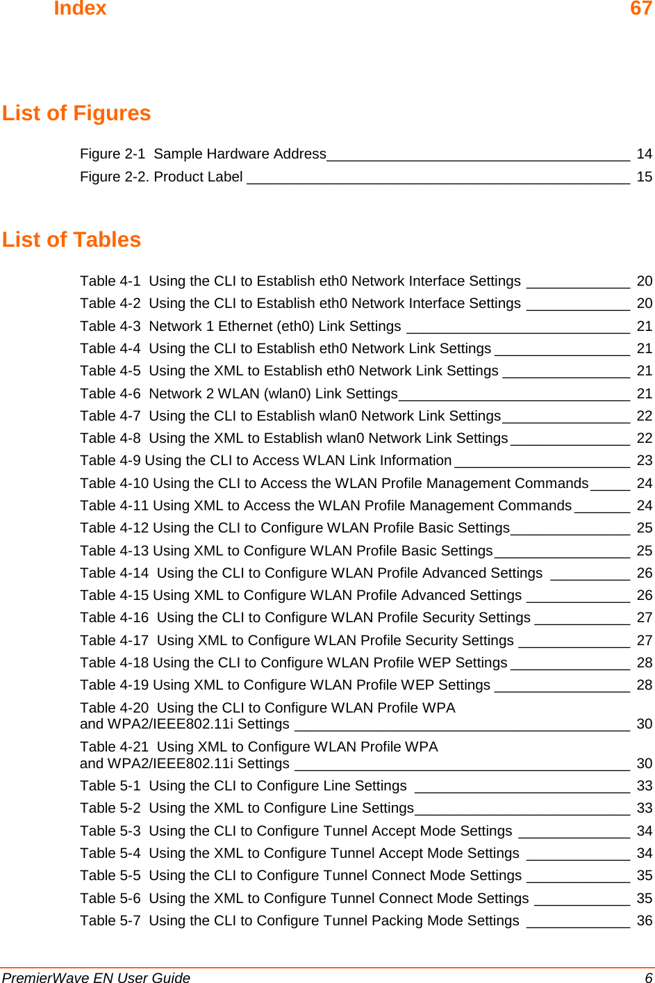
![E: USB-CDC-ACM Device Driver File for Windows Hosts PremierWave EN User Guide 66 [DriverService.NTamd64] DisplayName=%SERVICE% ServiceType=1 StartType=3 ErrorControl=1 ServiceBinary=%12%\USBSER.sys ;------------------------------------------------------------------------------ ; Vendor and Product ID Definitions ;------------------------------------------------------------------------------ ; When developing your USB device, the VID and PID used in the PC side ; application program and the firmware on the microcontroller must match. ; Modify the below line to use your VID and PID. Use the format as shown ; below. ; Note: One INF file can be used for multiple devices with different ; VID and PIDs. For each supported device, append ; ",USB\VID_xxxx&PID_yyyy" to the end of the line. ;------------------------------------------------------------------------------ [SourceDisksFiles] [SourceDisksNames] [DeviceList] %DESCRIPTION%=DriverInstall, USB\VID_0525&PID_A4A7, USB\VID_0525&PID_A4AB&MI_02 [DeviceList.NTamd64] %DESCRIPTION%=DriverInstall, USB\VID_0525&PID_A4A7, USB\VID_0525&PID_A4AB&MI_02 ;------------------------------------------------------------------------------ ; String Definitions ;------------------------------------------------------------------------------ ;Modify these strings to customize your device ;------------------------------------------------------------------------------ [Strings] Linux = "Linux Developer Community" DESCRIPTION = "Gadget Serial" SERVICE = "USB RS-232 Emulation Driver"](https://usermanual.wiki/lantronix/PEN/User-Guide-1524692-Page-66.png)