lantronix PEN PremierWave EN Wireless Device Server User Manual PremierWave EN User Guide
lantronix PremierWave EN Wireless Device Server PremierWave EN User Guide
Manual

Part Number 900-579
Revision A January 2011
PremierWaveTM EN
User Guide

PremierWave EN User Guide 2
Copyright & Trademark
© 2011 Lantronix. All rights reserved. No part of the contents of this book may be transmitted
or reproduced in any form or by any means without the written permission of Lantronix.
Printed in the United States of America.
Ethernet is a trademark of XEROX Corporation. Windows is a trademark of Microsoft
Corporation. Linux is a registered trademark of Linus Torvalds.
Contacts
Lantronix Corporate Headquarters
167 Technology Drive
Irvine, CA 92618, USA
Phone: 949-453-3990
Fax: 949-450-7249
Technical Support
Online: www.lantronix.com/support
Sales Offices
For a current list of our domestic and international sales offices, go to the Lantronix web site
at www.lantronix.com/about/contact.
Disclaimer & Revisions
The information in this guide may change without notice. The manufacturer assumes no
responsibility for any errors that may appear in this guide.
Revision History
Date
Rev.
Comments
January 2011
A
Initial Document.

PremierWave EN User Guide 3
Table of Contents
Copyright & Trademark ___________________________________________________ 2
Contacts ______________________________________________________________ 2
Disclaimer & Revisions ___________________________________________________ 2
Revision History ________________________________________________________ 2
Table of Contents _______________________________________________________ 3
List of Figures __________________________________________________________ 6
List of Tables ___________________________________________________________ 6
1: Using This Guide 9
Purpose and Audience ___________________________________________________ 9
Summary of Chapters ____________________________________________________ 9
Additional Documentation ________________________________________________ 11
2: Introduction 12
Key Features __________________________________________________________ 12
Applications ___________________________________________________________ 12
Protocol Support _______________________________________________________ 13
Troubleshooting Capabilities ______________________________________________ 13
Configuration Methods __________________________________________________ 13
Addresses and Port Numbers _____________________________________________ 14
Hardware Address __________________________________________________ 14
IP Address ________________________________________________________ 14
Port Numbers ______________________________________________________ 14
Product Information Label ________________________________________________ 15
3: Using DeviceInstaller 16
Accessing PremierWave EN using DeviceInstaller ____________________________ 16
Device Details Summary _________________________________________________ 17
4: Network Settings 19
Network Interface Settings _______________________________________________ 19
Network Link Settings ___________________________________________________ 21
WLAN Settings ________________________________________________________ 22
WLAN Link Information Commands _____________________________________ 22
WLAN Profiles _________________________________________________________ 24
WLAN Profile Management Commands _________________________________ 24
WLAN Profile Basic Settings __________________________________________ 25
WLAN Profile Advanced Settings _______________________________________ 25
WLAN Profile Security Settings ________________________________________ 26

PremierWave EN User Guide 4
WLAN Profile WEP Settings ___________________________________________ 27
WLAN Profile WPA and WPA2/IEEE802.11i Settings _______________________ 28
5: Line and Tunnel Settings 31
RS232/RS485 ______________________________________________________ 31
USB-CDC-ACM ____________________________________________________ 31
Line Settings __________________________________________________________ 32
Tunnel Settings ________________________________________________________ 33
Accept Mode _______________________________________________________ 33
Connect Mode _____________________________________________________ 35
Packing Mode ______________________________________________________ 36
6: Configurable Pin Manager 37
CPM: Configurable Pins _________________________________________________ 37
CPM: Groups ______________________________________________________ 39
7: Services Settings 40
DNS Configuration _____________________________________________________ 40
Syslog Configuration ____________________________________________________ 40
8: Security Settings 41
SSL Settings __________________________________________________________ 41
Certificate Upload Settings ____________________________________________ 41
Authority Certificate Settings __________________________________________ 42
Certificate and Key Generation ________________________________________ 42
9: Maintenance and Diagnostics Settings 44
File System Configuration ________________________________________________ 44
File Display Commands ______________________________________________ 44
File Modification Commands __________________________________________ 44
File Transfer Commands _____________________________________________ 45
Query Port ____________________________________________________________ 45
Diagnostics ___________________________________________________________ 46
IP Sockets_________________________________________________________ 46
Ping ______________________________________________________________ 46
Trace route ________________________________________________________ 46
DNS Lookup _______________________________________________________ 47
Memory ___________________________________________________________ 47
Processes _________________________________________________________ 47
System Configuration ___________________________________________________ 48

PremierWave EN User Guide 5
10: Advanced Settings 49
Command Line Interface Settings __________________________________________ 49
Basic CLI Settings __________________________________________________ 49
Telnet Settings _____________________________________________________ 50
SSH Settings ______________________________________________________ 50
XML Configuration _____________________________________________________ 51
XML: Export Configuration ____________________________________________ 51
XML: Import System Configuration Page _________________________________ 52
Import Configuration from External File __________________________________ 52
11: Tunneling 53
Connect Mode _________________________________________________________ 53
Accept Mode __________________________________________________________ 53
Packing Mode _________________________________________________________ 54
12: Security in Detail 55
Secure Sockets Layer (SSL) ______________________________________________ 55
Certificates ________________________________________________________ 55
Utilities _______________________________________________________________ 56
OpenSSL _________________________________________________________ 56
Steel Belted RADIUS ________________________________________________ 56
FreeRADIUS _______________________________________________________ 57
13: Updating Firmware 58
Obtaining Firmware _____________________________________________________ 58
Loading New Firmware __________________________________________________ 58
A: Technical Support 59
B: Binary to Hexadecimal Conversions 60
Converting Binary to Hexadecimal _________________________________________ 60
Conversion Table ___________________________________________________ 60
Scientific Calculator_____________________________________________________ 61
C: Compliance 62
D: Warranty 64
E: USB-CDC-ACM Device Driver File for Windows Hosts 65

PremierWave EN User Guide 6
Index 67
List of Figures
Figure 2-1 Sample Hardware Address______________________________________ 14
Figure 2-2. Product Label ________________________________________________ 15
List of Tables
Table 4-1 Using the CLI to Establish eth0 Network Interface Settings _____________ 20
Table 4-2 Using the CLI to Establish eth0 Network Interface Settings _____________ 20
Table 4-3 Network 1 Ethernet (eth0) Link Settings ____________________________ 21
Table 4-4 Using the CLI to Establish eth0 Network Link Settings _________________ 21
Table 4-5 Using the XML to Establish eth0 Network Link Settings ________________ 21
Table 4-6 Network 2 WLAN (wlan0) Link Settings _____________________________ 21
Table 4-7 Using the CLI to Establish wlan0 Network Link Settings ________________ 22
Table 4-8 Using the XML to Establish wlan0 Network Link Settings _______________ 22
Table 4-9 Using the CLI to Access WLAN Link Information ______________________ 23
Table 4-10 Using the CLI to Access the WLAN Profile Management Commands _____ 24
Table 4-11 Using XML to Access the WLAN Profile Management Commands _______ 24
Table 4-12 Using the CLI to Configure WLAN Profile Basic Settings _______________ 25
Table 4-13 Using XML to Configure WLAN Profile Basic Settings _________________ 25
Table 4-14 Using the CLI to Configure WLAN Profile Advanced Settings __________ 26
Table 4-15 Using XML to Configure WLAN Profile Advanced Settings _____________ 26
Table 4-16 Using the CLI to Configure WLAN Profile Security Settings ____________ 27
Table 4-17 Using XML to Configure WLAN Profile Security Settings ______________ 27
Table 4-18 Using the CLI to Configure WLAN Profile WEP Settings _______________ 28
Table 4-19 Using XML to Configure WLAN Profile WEP Settings _________________ 28
Table 4-20 Using the CLI to Configure WLAN Profile WPA
and WPA2/IEEE802.11i Settings __________________________________________ 30
Table 4-21 Using XML to Configure WLAN Profile WPA
and WPA2/IEEE802.11i Settings __________________________________________ 30
Table 5-1 Using the CLI to Configure Line Settings ___________________________ 33
Table 5-2 Using the XML to Configure Line Settings ___________________________ 33
Table 5-3 Using the CLI to Configure Tunnel Accept Mode Settings ______________ 34
Table 5-4 Using the XML to Configure Tunnel Accept Mode Settings _____________ 34
Table 5-5 Using the CLI to Configure Tunnel Connect Mode Settings _____________ 35
Table 5-6 Using the XML to Configure Tunnel Connect Mode Settings ____________ 35
Table 5-7 Using the CLI to Configure Tunnel Packing Mode Settings _____________ 36

PremierWave EN User Guide 7
Table 5-8 Using the XML to Configure Tunnel Packing Mode Settings ____________ 36
Table 7-1 DNS Configuration _____________________________________________ 40
Table 7-2 Syslog Configuration ___________________________________________ 40
Table 8-1 Certificate Upload Settings ______________________________________ 41
Table 8-2 Using the CLI to Upload an Existing SSL Certificate/Key Pair ___________ 41
Table 8-3 Using XML to Upload an Existing SSL Certificate/Key Pair _____________ 41
Table 8-4 Authority Certificate Settings _____________________________________ 42
Table 8-5 Using the CLI to Upload an Authority Certificate ______________________ 42
Table 8-6 Using XML to Upload an Authority Certificate ________________________ 42
Table 8-7 Certificate and Key Generation ___________________________________ 42
Table 8-8 Using the CLI to Generate a Certificate/Key Pair _____________________ 43
Table 9-1 File Display Commands _________________________________________ 44
Table 9-2 Using the CLI to Display File Information ___________________________ 44
Table 9-3 File Modification Commands _____________________________________ 44
Table 9-4 Using the CLI to Modify PremierWave Files _________________________ 44
Table 9-5 File Transfer Commands ________________________________________ 45
Table 9-6 Using the CLI to Transfer Files ___________________________________ 45
Table 9-7 Query Port Settings ____________________________________________ 45
Table 9-8 Using the CLI to Configure Query Port Settings ______________________ 45
Table 9-9 Using XML to Configure Query Port Settings ________________________ 45
Table 9-10 Using the CLI to View IP Sockets ________________________________ 46
Table 9-11 Ping Settings ________________________________________________ 46
Table 9-12 Using the CLI to Ping a Remote Host _____________________________ 46
Table 9-13 Trace Route Settings __________________________________________ 46
Table 9-14 Using the CLI to Perform the Trace Route Command ________________ 47
Table 9-15 Using Forward or Reverse DNS Lookup ___________________________ 47
Table 9-16 Using the CLI to Perform a DNS Lookup ___________________________ 47
Table 9-17 Using the CLI to View Memory Statistics ___________________________ 47
Table 9-18 Using the CLI to Display the Running Processes ____________________ 47
Table 9-19 System Settings ______________________________________________ 48
Table 9-20 Using the CLI to Reboot or Restore Factory Defaults _________________ 48
Table 10-1 CLI Configuration Settings ______________________________________ 49
Table 10-2 Using the CLI to Configure the Basic CLI Settings ___________________ 49
Table 10-3 Using XML to Configure the Basic CLI Settings _____________________ 49
Table 10-4 Telnet Settings _______________________________________________ 50
Table 10-5 Using the CLI to Configure Telnet Settings _________________________ 50
Table 10-6 Using XML to Configure Telnet Settings ___________________________ 50
Table 10-7 SSH Settings ________________________________________________ 50
Table 10-8 Using the CLI to Configure the SSH Settings _______________________ 50
Table 10-9 Using XML to Configure the SSH Settings _________________________ 50
Table 10-10 Exporting a System Configuration Record ________________________ 51
Table 10-11 Using the CLI to Export the XML Settings _________________________ 51


PremierWave EN User Guide 9
1: Using This Guide
Purpose and Audience
This guide provides the information needed to configure, use, and update the PremierWave
EN. It is intended for software developers and system integrators who are embedding
PremierWave in their designs.
Summary of Chapters
The remaining chapters in this guide include:
Chapter
Description
2: Introduction Main features of the product and the protocols it
supports. Includes technical specifications.
3: Using DeviceInstaller Instructions for viewing the current configuration
using DeviceInstaller.
4: Network Settings Instructions for configuring network settings.
5: Line and Tunnel Settings Instructions for configuring line and tunnel settings.
6: Configurable Pin Manager Information about the Configurable Pin Manager
(CPM) and how to set the configurable pins to work
with a device.
7: Services Settings Instructions for configuring DNS and Syslog
settings.
8: Security Settings Instructions for configuring SSL security settings.
9: Maintenance Instructions to maintain the PremierWave EN, view
statistics, files, and diagnose problems.
10: Advanced Settings Instructions for configuring CLI and XML settings.
11: Tunneling Information about tunneling features available on
the serial lines.
12: Security in Detail Detailed description and configuration of SSL
security settings.
13: Updating Firmware Instructions for obtaining the latest firmware and
updating the PremierWave EN.

1: Using This Guide
PremierWave EN User Guide 10
Chapter
Description
A: Technical Support Instructions for contacting Lantronix Technical
Support.
B: Binary to Hexadecimal Conversions Instructions for converting binary values to
hexadecimals.
C: Compliance Lantronix compliance information.
D: Warranty Lantronix warranty statement.
E: USB-CDC-ACM Device Driver File for
Windows Hosts Information about the device driver file for windows
host.

1: Using This Guide
PremierWave EN User Guide 11
Additional Documentation
Visit the Lantronix Web site at www.lantronix.com/support/documentatio for the latest
documentation and the following additional documentation. n
Document
Description
PremierWave EN Integration Guide
Information about the PremierWave EN hardware,
testing the PremierWave EN using the demonstration
board, and integrating the PremierWave EN into your
product.
PremierWave EN Command Reference
Instructions for accessing Command Mode (the
command line interface) using a Telnet connection,
SSH connection or through the serial port. Detailed
information about the commands. Also provides details
for XML configuration and status.
PremierWave Eval Board Quick Start
Instructions for getting the PremierWave EN
demonstration board up and running.
PremierWave Eval Board User Guide
Information needed to use the PremierWave
on the demo board.
DeviceInstaller Online Help
Instructions for using the Lantronix Windows-based
utility to locate the PremierWave EN and to view its
current settings.
Com Port Redirector Quick Start and
Online Help
Instructions for using the Lantronix Windows-based
utility to create virtual com ports.
Secure Com Port Redirector User Guide
Instructions for using the Lantronix Windows-based
utility to create secure virtual com ports.

PremierWave EN User Guide 12
2: Introduction
The PremierWave EN embedded Ethernet Device Server is a complete network-enabling
solution in a 30 (1.181) X 55 (2.165) X 6.45 (0.248) package. This miniature device server
empowers original equipment manufacturers (OEMs) to go to market quickly and easily with
Ethernet and/or wireless networking and web page serving capabilities built into their
products. [DIMS = mm (in.)]
Key Features
Power Supply: Regulated 3.3V input required. There is a step-down converter to 1.5 volts
for the processor core and 1.8 volts for the memory subsystem. All voltages have LC
filtering to minimize noises and emissions.
Controller: 32-bit ARM9 microprocessor running at 400 MHz with 32kB Data Cache and
32 kB Instruction Cache Memory: Up to 64 MB SDRAM and 256 MB NAND Flash
(Default 64 MB each). Up to 16 MB serial SPI Flash (Default 8 MB).
Ethernet: 10/100 Mbps Ethernet transceiver.
Wireless: Dual Band 802.11 a/b/g/n with an on-board antenna and option for external
antennas and diversity.
Serial Ports: Two high speed RS232/RS422/RS485 serial ports with all hardware
handshaking signals. Baud rate is software selectable (300 bps to 921600 bps). One
emulated serial port on the USB Device Port (up to Full Speed 12 Mbps), using standard
CDC-ACM protocol.
Two USB 2.0 Full Speed (12 Mbps) Host ports
USB 2.0 Full Speed (12 Mbps) Device port
Master/Slave high speed SPI interface
I2C interface
Configurable I/O Pins (CPs): Up to nine pins are configurable as general purpose I/Os if
no DTR or DCD is used on serial ports. Not 5V tolerant.
Interface Signals: 3.3V-level interface signals.
Temperature Range: Operates over an extended temperature range of -40°C to +85°C.
Applications
The PremierWave EN device server connects serial devices such as those listed below to
Ethernet networks using the IP protocol family.
ATM machines
CNC controllers
Data collection devices
Universal Power Supply (UPS) management unit
Telecommunications equipment

2: Introduction
PremierWave EN User Guide 13
Data display devices
Security alarms and access control devices
Handheld instruments
Modems
Time/attendance clocks and terminals’
Patient Monitoring Devices
Glucose Analyzers
Infusion Pumps
Protocol Support
The PremierWave EN device server contains a full-featured IP stack. Supported protocols
include:
ARP, IP, UDP, TCP, ICMP, BOOTP, DHCP, Auto IP, Telnet, DNS, FTP, TFTP, SSH,
SSL/TLS, and Syslog for network communications and management.
TCP, UDP, tunneling to the serial port.
TFTP for uploading/downloading files.
FTP for firmware upgrades and uploading/downloading files.
Troubleshooting Capabilities
The PremierWave EN offers a comprehensive diagnostic toolset that lets you troubleshoot
problems quickly and easily. Available from the CLI, the diagnostic tools let you:
View memory and IP socket information.
Perform ping and traceroute operations.
Conduct forward or backup DNS lookup operations.
View all processes currently running on the PremierWave EN, including CPU utilization.
View system log messages.
Configuration Methods
After installation, the PremierWave EN requires configuration. For the unit to operate
correctly on a network, it must have a unique IP address on the network. There are three
basic methods for logging into the PremierWave EN and assigning IP addresses and other
configurable settings:
DeviceInstaller: Configure the IP address and related settings and view current settings on
the PremierWave EN using a Graphical User Interface (GUI) on a PC attached to a network.
(See page 16.)
Command Mode: There are two methods for accessing Command Mode (CLI): making a
Telnet or SSH connection, or connecting a terminal (or a PC running a terminal emulation
program) to the unit’s serial port. (See the PremierWave EN Command Reference Guide for
instructions and available commands.)

2: Introduction
PremierWave EN User Guide 14
XML: The PremierWave EN supports XML-based configuration and setup records that make
device configuration transparent to users and administrators. XML is easily editable with a
standard text or XML editor. (See the PremierWave EN Command Reference Guide for
instructions and commands.)
Addresses and Port Numbers
Hardware Address
The hardware address is also referred to as the Ethernet address or MAC address.
Figure 2-1 Sample Hardware Address
00-20-4A-14-01-18 or 00:20:4A:14:01:18
IP Address
Every device connected to an IP network must have a unique IP address. This address
references the specific unit.
Port Numbers
Every TCP connection and every UDP datagram is defined by a destination and source IP
address, and a destination and source port number. For example, a Telnet server commonly
uses TCP port number 23.
The following is a list of the default server port numbers running on the PremierWave EN:
TCP Port 22: SSH Server (Command Mode configuration)
TCP Port 23: Telnet Server (Command Mode configuration)
TCP Port 21: FTP
UDP Port 30718: LDP (Lantronix Discovery Protocol) port
TCP/UDP Port 10001: Tunnel 1
TCP/UDP Port 10002: Tunnel 2
TCP/UDP Port 10003: Tunnel 3

2: Introduction
PremierWave EN User Guide 15
Product Information Label
The product information label on the unit contains the following information about the specific
unit:
Bar code
Product Revision
Part number
Hardware Address (MAC Address)
Manufacturing Date Code
Figure 2-2. Product Label

PremierWave EN User Guide 16
3: Using DeviceInstaller
This chapter covers the steps for locating a PremierWave EN unit and viewing its properties
and device details.
Notes:
For instructions on using DeviceInstaller to configure the IP address and related
settings or for more advanced features, see the Device Installer online Help.
Auto IP generates a random IP address in the range of 169.254.0.1 to
169.254.255.254, with a netmask of 255.255.0.0, if no BOOTP or DHCP server is
found.
Accessing PremierWave EN using DeviceInstaller
Note: Make note of the MAC address. It is needed to locate the PremierWave EN using
DeviceInstaller.
To use the DeviceInstaller utility, first install the latest version from the downloads page on
the Lantronix web site www.lantronix.com/downloads.
1. Run the executable to start the installation process and respond to the installation wizard
prompts. (If prompted to select an installation type, select Typical.)
2. Click StartAll ProgramsLantronixDeviceInstaller DeviceInstaller.
3. When DeviceInstaller starts, it will perform a network device search. To perform another
search, click the “Search” button.
4. Expand the PremierWave folder by clicking the + symbol next to the PremierWave folder
icon. The list of available Lantronix PremierWave EN devices appears.
5. Select the PremierWave EN unit by expanding its entry and clicking on its IP address to
view its configuration.
6. On the right page, click the Device Details tab. The current PremierWave EN
configuration appears. This is only a subset of the full configuration; the full configuration
may be accessed via CLI or XML.

3: Using DeviceInstaller
PremierWave EN User Guide 17
Device Details Summary
Note: The settings are Display Only in this table unless otherwise noted.
Current Settings
Description
Name
Name identifying the PremierWave EN.
DHCP Device Name The name associated with the PremierWave EN module’s current
IP address, if the IP address was obtained dynamically.
Group
Configurable field. Enter a group to categorize the PremierWave
EN. Double-click the field, type in the value, and press Enter to
complete. This group name is local to this PC and is not visible on
other PCs or laptops using DeviceInstaller.
Comments Configurable field. Enter comments for the PremierWave EN.
Double-click the field, type in the value, and press Enter to
complete. This description or comment is local to this PC and is
not visible on other PCs or laptops using DeviceInstaller.
Device Family
Shows the PremierWave EN device family type as “PremierWave”.
Type
Shows the device type as “PremierWave EN”.
ID
Shows the PremierWave EN ID embedded within the unit.
Hardware Address
Shows the PremierWave EN hardware (MAC) address.
Firmware Version
Shows the firmware currently installed on the PremierWave EN.
Extended Firmware Version
Provides additional information on the firmware version.
Online Status Shows the PremierWave EN status as Online, Offline,
Unreachable (the PremierWave EN is on a different subnet), or
Busy (the PremierWave EN is currently performing a task).
IP Address
Shows the PremierWave EN current IP address. To change the IP
address, click the Assign IP button on the DeviceInstaller menu
bar.
IP Address was Obtained
Appears “Dynamically” if the PremierWave EN automatically
received an IP address (e.g., from DHCP). Appears “Statically” if
the IP address was configured manually.
If the IP address was assigned dynamically, the following fields
appear:
Obtain via DHCP with values of True or False.
Obtain via BOOTP with values of True or False.
Subnet Mask
Shows the subnet mask specifying the network segment on which
the PremierWave EN resides.
Gateway
Shows the IP address of the router of this network.
There is no default.
Number of Ports
Shows the number of serial ports on this PremierWave EN.
Supports Configurable Pins
Shows True, indicating configurable pins are available on the
PremierWave EN.
Supports Email Triggers Shows True, indicating email triggers are available on the
PremierWave EN.
Telnet Enabled
Indicates whether Telnet is enabled on this PremierWave EN.

3: Using DeviceInstaller
PremierWave EN User Guide 18
Current Settings
Description
Telnet Port
Shows the PremierWave EN port for Telnet sessions.
Web Enabled
Indicates whether Web Manager access is enabled on this
PremierWave EN.
Web Port
Shows the PremierWave EN port for Web Manager configuration
(if Web Enabled field is True).
Firmware Upgradeable
Shows True, indicating the PremierWave EN firmware is
upgradeable as newer versions become available.

PremierWave EN User Guide 19
4: Network Settings
The Network Settings show the status of the Ethernet or WLAN interface/link and let you
configure the settings on the device. Interface settings are related to the configuration of the
IP and related protocols. Link settings are related to the physical link connection, which
carries the IP traffic.
The PremierWave EN contains two network interfaces, only one of which may be active at a
time. The Ethernet interface is also called interface 1 or eth0, and the WLAN interface is
called interface 2 or wlan0.
Note: Some settings require a reboot to take effect. These settings are noted below.
Network Interface Settings
This table shows the settings for the network interface configuration. These settings apply to
both the Ethernet and WLAN interfaces, but are configured independently for each interface.
Network Interface
Configuration Settings
Description
State
Enables or disables the interface.
BOOTP
Select Enable or Disable. At boot up, after the physical link is up, the
PremierWave EN will attempt to obtain IP settings from a BOOTP server.
Notes: Overrides the configured IP address/mask, gateway, hostname,
and domain.
When DHCP is Enable, the system automatically uses DHCP, regardless
of whether BOOTP is Enable.
Changing this value requires you to reboot the device.
DHCP
Select Enable or Disable. At boot up, after the physical link is up, the
PremierWave EN will attempt to obtain IP settings from a DHCP server
and will periodically renew these settings with the server.
Notes: Overrides BOOTP, the configured IP address/mask, gateway,
hostname, and domain.
Changing this value requires you to reboot the device.
IP Address
Enter the static IP address to use for the interface. You may enter it alone
or in CIDR format.
Notes: This setting will be used if Static IP is active (both DHCP and
BOOTP are Disable).
Changing this value requires you to reboot the device.
When DHCP or BOOTP is enabled, the PremierWave EN tries to obtain
an IP address from a DHCP or BOOTP server. If it cannot, the
PremierWave EN generates and uses an Auto IP address in the range of
169.254.xxx.xxx, with a network mask of 255.255.0.0.
Default Gateway
Enter the IP address of the router for this network.
Note: This setting will be used if Static IP is active (both DHCP and
BOOTP are
Disable
).

4: Network Settings
PremierWave EN User Guide 20
Network Interface
Configuration Settings
Description
Hostname
Enter the hostname for the interface. It must begin with a letter or number,
continue with a sequence of letters, numbers, or hyphens, and end with a
letter or number.
Note: This setting will take effect immediately, but will not register the
hostname with a DNS server until the next reboot.
Domain
Enter the domain name suffix for the interface.
Note: This setting will be used when either Static IP or Auto IP is active,
or if DHCP/BOOTP is active and no Domain Suffix was acquired from the
server
.
DHCP Client ID
Enter the ID if the DHCP server requires a DHCP Client ID option. The
DHCP server’s lease table shows IP addresses and MAC addresses for
devices. The lease table shows the Client ID, in hexadecimal notation,
instead of the PremierWave EN MAC address.
Primary DNS
Enter the IP address of the primary Domain Name Server.
Note: This setting will be used when either Static IP or Auto IP is active,
or if DHCP/BOOTP is active and no DNS server was acquired from the
server.
Secondary DNS
Enter the IP address of the secondary Domain Name Server.
Note: This setting will be used when either Static IP or Auto IP is active,
or if DHCP/BOOTP is active and no DNS server was acquired from the
server.
Table 4-1 Using the CLI to Access Network Interface Settings
Command Level - eth0
enable->config->if 1
Command Level - wlan0
enable->config->if 2
Table 4-2 Using XML to Access Network Interface Settings
Configuration group - eth0
configgroup name = "interface" instance = "eth0"
Configuration group - wlan0
configgroup name = "interface" instance = "wlan0"

4: Network Settings
PremierWave EN User Guide 21
Network Link Settings
The Network Link settings allow you to configure the physical link parameters for a Network
Interface. The Ethernet and WLAN link settings are described below.
Table 4-3 Network 1 Ethernet (eth0) Link Settings
Network 1 Ethernet (eth0)
Link Settings
Description
Speed
Select the Ethernet link speed. (Default is Auto)
Auto = Auto-negotiation of Link Speed
10 = Force 10 Mbps
100
= Force 100 Mbps
Duplex Select the Ethernet link duplex mode. (Default is Auto)
Auto = Auto-negotiation of Link Duplex
Half = Force Half Duplex
Full
= Force Full Duplex
Table 4-4 Using the CLI to Access Network Link Settings
Command level - eth0
enable->config->if 1->link
Table 4-5 Using XML to Access Network Link Settings
Configuration group - eth0
configgroup name = "ethernet" instance = "eth0"
Notes:
When speed is Auto, duplex must be Auto or Half.
When speed is not Auto, duplex must be Half or Full.
Fixed speed Full duplex will produce errors connected to Auto, due to duplex mismatch.
Table 4-6 Network 2 WLAN (wlan0) Link Settings
Network 2 WLAN (wlan0)
Link Settings
Description
Choice 1 Profile
Choice 2 Profile
Choice 3 Profile
Choice 4 Profile
Up to four (4) WLAN Profiles may be selected for automatic connection to
wireless networks. More information on wireless settings is available in
WLAN Settings on page 22.
Enter the name of the WLAN Profile desired for each choice.

4: Network Settings
PremierWave EN User Guide 22
Network 2 WLAN (wlan0)
Link Settings
Description
Debugging Level
The Debugging Level sets the verbosity level for printing WLAN Link
messages to the TLOG. (Default is Info)
Available levels, from most to least verbose:
Dump
Debug
Info
Warning
Error
Table 4-7 Using the CLI to Access Network Link Settings
Command level - wlan0
enable->config->if 2->link
Command level - wlan0
enable->config->if 2->link->choice 1|2|3|4
Table 4-8 Using XML to Access Network Link Settings
Configuration group - wlan0
configgroup name = "wlan" instance = "wlan0"
WLAN Settings
WLAN Link Information Commands
These commands display information about the current state wireless network.
WLAN Link Information
Commands
Description
Scan “<network SSID>”
Performs a scan for devices within range of the PremierWave EN.
Including the optional network SSID limits the scan to devices
configured with the specified network SSID. Omitting the network SSID
performs a scan for all devices in range.
Note: When omitting the network SSID it is still necessary to include the
opening and closing quotation marks (scan “”).
Status
Displays status information about the WLAN link.
The results of the scan command are presented in the following format:
WLAN Link Scan Results Field
Description
BSSID
Basic Service Set Identifier.
Frequency
The frequency on which the device is operating.
Signal Level
The Received Signal Strength Indication (RSSI) of the device
measured in dBm.

4: Network Settings
PremierWave EN User Guide 23
WLAN Link Scan Results Field
Description
Flags Indicates the security suite in use by the device as well as
whether it is operating in Adhoc (IBSS) mode.
SSID
The Service Set Identifier (network name) of the device.
The results of the status command are presented in the following format:
WLAN Link Status Results Field
Description
Type
Indicates this is a WLAN link
BSSID A unique identifier for the Basic Service Set corresponding to
the MAC address of the Access Point in infrastructure mode,
or a generated value in Adhoc mode.
SSID
The Service Set Identifier of the connected network.
Topology
The type of wireless network in use for the current association
(Adhoc or Infrastructure).
Active WLAN Profile
Indicates which WLAN profile created the current connection
to the wireless network.
Pairwise Cipher
The standard used to encrypt a particular type of data in the
current wireless association.
Group Cipher
The standard used to encrypt a particular type of data in the
current wireless association.
Security Suite
Indicates the security suite used for the current association.
Channel
The channel used for the current association.
IP Address
The IP address assigned to the PremierWave EN
RSSI
A measure of the power level of the received radio signal in
dBm.
Table 4-9 Using the CLI to Access WLAN Link Information
Command level
enable>configure>if 2>link

4: Network Settings
PremierWave EN User Guide 24
WLAN Profiles
A WLAN profile defines all of the settings necessary to establish a wireless connection with
either an access point (in infrastructure mode) or another wireless client (in Adhoc mode.) A
maximum of six profiles can exist on the PremierWave EN at a time. Of these, up to four can
be configured as active (see Profile Choices under WLAN Settings on page 22).
WLAN Profile Management Commands
These commands create, edit and remove WLAN profiles on the PremierWave EN.
WLAN Profile Management
Commands
Description
Show
Display the currently configured WLAN profiles.
Create
Creates a new WLAN profile with default settings.
Edit
Selects a WLAN profile for editing. Editing begins at the ‘Basic’ level
settings for the specified profile.
Delete
Permanently deletes a WLAN profile from the PremierWave EN.
Apply wlan
Immediately applies all changes made to the WLAN configuration
without saving them in persistent storage.
Note: This command is available at all levels within the WLAN
profile.
Write
Immediately applies all changes made to the WLAN configuration
and saves them to persistent storage.
Note: This command is available at all levels within the WLAN
profile.
Table 4-10 Using the CLI to Access the WLAN Profile Management Commands
Command level
enable>configure>wlan profiles
Table 4-11 Using XML to Access the WLAN Profile Management Commands
Configuration group name
wlan profile:(profile name)

4: Network Settings
PremierWave EN User Guide 25
WLAN Profile Basic Settings
WLAN Profile Basic Settings
Description
Network Name The name of the wireless network (SSID.)
Note: The PremierWave EN performs only passive scans on
the DFS channels (52–140.) In order for the PremierWave
EN to connect with an access point on one of these channels,
the access point must be configured to broadcast the SSID in
its beacons.
Topology
Specifies Infrastructure (ESS) or Adhoc (IBSS) mode.
Infrastructure: mode that communicates with access
points.
Adhoc: mode that communicates with other clients.
Channel
Specifies the channel for an Adhoc network.
Note: This setting only applies to the creation of an Adhoc
network.
Table 4-12 Using the CLI to Configure WLAN Profile Basic Settings
Command level
enable>configure>wlan profiles>edit (profile name)
or
enable>configure>wlan profiles>edit (profile #)
Table 4-13 Using XML to Configure WLAN Profile Basic Settings
Configuration group name
wlan profile:(profile name)
WLAN Profile Advanced Settings
WLAN Profile Advanced Settings
Description
TX Data Rate Maximum
Specifies the rate for data transmission.
Note: This setting only applies if ‘TX Data Rate’ is set to
‘Fixed’.
TX Data Rate PremireWave lets you control the transmission data rate or
controls it automatically.
Fixed = keeps the transmission rate at the configured
value.
Auto-reduction = allows the PremierWave EN to reduce
the data rate automatically, depending on link quality.
TX Power Maximum
Maximum transmission output power in dBm.

4: Network Settings
PremierWave EN User Guide 26
WLAN Profile Advanced Settings
Description
Antenna Diversity Selects the antenna the radio will use or allows the
PremierWave EN to automatically make the selection.
Enabled = allow the PremierWave EN to select the
antenna.
Antenna 1 = use the internal antenna.
Antenna 2 = use the external antenna.
Power Management
Power management reduces the overall power consumption
of the PremierWave EN unit, but can increase latency.
Enabled = allows the PremierWave EN to turn off the
receiver when it is idling.
Disabled = keeps the receiver on at all times.
Power Management Interval
Number of beacons (100 ms interval) between 1 and 10. The
above-mentioned latency can be up to this number X 100ms.
Table 4-14 Using the CLI to Configure WLAN Profile Advanced Settings
Command level
enable>configure>wlan profiles>edit (profile
name)>advanced
Table 4-15 Using XML to Configure WLAN Profile Advanced Settings
Configuration group name
wlan profile:(profile name)
WLAN Profile Security Settings
The PremierWave EN supports WEP, WPA, and WPA2/IEEE 802.11i to secure all wireless
communication. WPA and WPA2/IEEE 802.11i are not available for Adhoc topology.
The WPA2/IEEE 802.11i mode is compliant with the Robust Secure Network specified in the
IEEE standard 802.11i.
WLAN Profile Security Settings
Description
Suite
Specifies the security suite to be used for this profile.
None = no authentication or encryption method will be used.
WEP = Wired Equivalent Privacy
WPA = WiFi Protected Access
WPA2
= Robust Secure Network.
Key Type
Selects the format of the security key.

4: Network Settings
PremierWave EN User Guide 27
WLAN Profile Security Settings
Description
Passphrase The passphrase consists of up to 63 characters.
Note: Lantronix recommends using a passphrase of 20
characters or more for maximum security. Spaces and
punctuation characters are permitted.
Note: The passphrase input is not the same as ASCII input (as
used on some products.) ASCII is translated directly into
hexadecimal bytes according to the ASCII table, while a possibly
larger passphrase is hashed into a key and provides better
security through a larger range of key values.
Table 4-16 Using the CLI to Configure WLAN Profile Security Settings
Command level
enable>configure>wlan profiles>edit (profile
name)>security
Table 4-17 Using XML to Configure WLAN Profile Security Settings
Configuration group name
wlan profile:(profile name)
WLAN Profile WEP Settings
WEP security is available in both Infrastructure and AdHoc modes. WEP is a simple and
efficient security mode encrypting the data via the RC4 algorithm. However, WEP has
become more vulnerable due to advances in hacking technology. State of the art equipment
can find WEP keys in five minutes. For stronger security, please use WPA, or better, WPA2
with AES (CCMP).
WLAN Profile WEP Settings
Description
Authentication
Selects the authentication method to be used.
Shared = encryption keys of both parties are compared as
a form of authentication. If mismatched, no connection is
established.
Open = a connection is established without first checking
for matching encryption keys. However, mismatched keys
will result in garbled data and thus a lack of connectivity at
the IP level.
Key Size
Key size in bits. Select 40 for WEP40 and WEP64, select
104 for WEP104 and WEP128.
TX Key Index
Selects one of four indexes listing keys for transmitting data.
Reception is allowed with all four keys.
Note: For operability with some products that generate four
identical keys from a passphrase, this index must be one.
Keys 1-4
Enter one or more encryption keys in hexadecimal format.
Enter 10 hexadecimal digits (0-9, a-f) for WEP40 and 26 for
WEP104. The configured keys are not shown for security
reasons.

4: Network Settings
PremierWave EN User Guide 28
Table 4-18 Using the CLI to Configure WLAN Profile WEP Settings
Command level
enable>configure>wlan profiles>edit (profile
name)>security>wep
Table 4-19 Using XML to Configure WLAN Profile WEP Settings
Configuration group name
wlan profile:(profile name)
WLAN Profile WPA and WPA2/IEEE802.11i Settings
WPA and WPA2/IEEE802.11i security suites are available for Infrastructure mode only.
WPA is a security standard specified by the WiFi Alliance and is a close derivative of an early
draft of the IEEE802.11i specification. WEP was becoming vulnerable and finalizing the
IEEE802.11i standard was still far away. WPA2 is WiFi’s subset of the broad IEEE802.11i
standard to enforce better interoperability. The PremierWave EN is compliant with both
WPA2 and IEEE802.11i.
WLAN Profile WPA & WPA2
Settings
Description
Authentication
Selects the authentication method to be used.
PSK = Pre-Shared Key. The same key needs to be configured
on both sides of the connection. (On the PremierWave EN and
on the Access Point.)
IEEE 802.1X = This authentication method communicates with a
RADIUS authentication server that is part of the network. The
RADIUS server will match the credentials sent by the
PremierWave EN with an internal database.
Key
64 hexadecimal digits (32 bytes.)

4: Network Settings
PremierWave EN User Guide 29
WLAN Profile WPA & WPA2
Settings
Description
IEEE 802.1X
Selects the protocol to use to authenticate the WLAN client.
LEAP = Lightweight Extensible Authentication Protocol. A
derivative of the original Cisco LEAP, which was a predecessor
of 802.1X. Real Cisco LEAP uses a special MAC layer
authentication (called Network EAP) and cannot work with
WPA/WPA2. The PremierWave EN uses a more generic version
to be compatible with other major brand WiFi equipment. The
authentication backend is the same.
EAP-TLS = Extensible Authentication Protocol - Transport Layer
Security. Uses the latest incarnation of the Secure Sockets
Layer (SSL) standard and is the most secure because it
requires authentication certificates on both the network side and
the PremierWave EN side.
EAP-TTLS = Extensible Authentication Protocol - Tunneled
Transport Layer Security.
PEAP = Protected Extensible Authentication Protocol.
EAP-TTLS and PEAP have been developed to avoid the
requirement of certificates on the client side (PremierWave EN),
which makes deployment more cumbersome. Both make use of
EAP-TLS to authenticate the server (network) side and establish
an encrypted tunnel. This is called the outer-authentication.
Then a conventional authentication method (MD5, MSCHAP,
etc.) is used through the tunnel to authenticate the PremierWave
EN. This is called inner authentication.
EAP-TTLS and PEAP have been developed by different
consortia and vary in details, of which the most visible is the
supported list of inner authentications.
Note: When using EAP-TLS, EAP-TTLS or PEAP authority, at
least one authority certificate will have to be installed in the SSL
configuration that is able to verify the RADIUS server’s certificate.
In case of EAP-TLS, also a certificate and matching private key
need to be configured to authenticate the PremierWave EN to the
RADIUS server. For more information about SSL certificates see
Secure Sockets Layer (SSL) on page ??. XXX FIXME: need link
here
EAP-TTLS Option
Selects the inner authentication method to be used with EAP-TTLS
(if configured.)
EAP-MSCHAPv2
MSCHAPv2
MSCHAP
CHAP
PAP
EAP-MD5
PEAP Option
Selects the inner authentication method to be used with EAP-PEAP
(if configured.)
EAP-MSCHAPv2
EAP-MD5
Username
Userid for identifying the PremierWave EN to the RADIUS server in
the network
Password
Password for identifying the PremierWave EN to the RADIUS
server in the network.

4: Network Settings
PremierWave EN User Guide 30
WLAN Profile WPA & WPA2
Settings
Description
Encryption
Select one or more encryption types, listed from strongest to least
strong. At least one selection will have to match the Access Points
intended to connect with.
CCMP = Uses AES as basis and is the strongest encryption
option.
TKIP = Uses WEP as the basis, but adds extra checks and
variations for added protection.
WEP = Based on RC4.
Note: In case the encryption settings on the Access Point(s) can
still be chosen, the capabilities of the Access Point(s) and the other
clients that need to use the network need to be taken into account.
RSA Certificate Name
Name of client certificate (required for EAP-TLS.) For more
information about SSL certificates see SSL Settings on page 41.
Table 4-20 Using the CLI to Configure WLAN Profile WPA
and WPA2/IEEE802.11i Settings
Command level
enable>configure>wlan profiles>edit (profile
name)>security>wpax
Table 4-21 Using XML to Configure WLAN Profile WPA
and WPA2/IEEE802.11i Settings
Configuration group name
wlan profile:(profile name)

PremierWave EN User Guide 31
5: Line and Tunnel Settings
The PremierWave EN contains three Lines. Lines 1 and 2 are standard RS232/RS485 serial
ports, while Line 3 is an emulated serial port over the USB Device (USB-CDC-ACM).
RS232/RS485
Lines 1 and 2 can be configured to operate in the following modes:
RS232
RS485 Full Duplex
RS485 Half Duplex, with and without termination impedance
All serial settings such as Baud Rate, Parity, Data Bits, etc, apply to these Lines.
USB-CDC-ACM
Line 3 can only operate as an emulated serial port over the USB Device port. It uses the
standard CDC-ACM protocol, which is supported natively by most host operating systems
(Windows, Linux, etc.). Since it is an emulated serial port, most standard serial port settings
are irrelevant. Flow control is inherent to the USB protocol, and the line speed (Baud Rate)
will be “as fast as conditions permit”.
When the PremierWave EN USB Device port is cabled to a host, it will identify itself with the
industry standard USB Vendor ID of 0x0525 and Product ID of 0xa4a7.
When attached to a Windows host, a device driver .inf file (see Appendix E - USB-CDC-ACM
Device Driver File for Windows Hosts) must be installed the first time the port is cabled.
Once installed, Windows will configure an available COM port, each time the USB cable is
attached.
CAUTION:
When attached to a Linux host, the USB-CDC-ACM connection will automatically be
configured, assuming the Linux host is configured for USB host operation and the “cdc_acm”
driver is available. Once recognized, the cdc_acm driver will configure a standard serial port
in the /dev/ttyACMx series, where x is a number 0, 1, 2, 3, etc.
Under Windows, if the PremierWave EN device is rebooted when an active
COM port is configured and in use, the COM port will come back up in an unstable
state. When this happens, any terminal program accessing the COM port must be
disconnected, and the USB cable physically replugged (or the COM port under Device
Manager disabled/enabled).
CAUTION:
Under Linux, if the /dev/ttyACMx device is in use when the PremierWave EN
is rebooted, some terminal programs under Linux will automatically disconnect while
others will not. If a terminal program does not disconnect automatically, when the
PremierWave EN comes back up, the CDC-ACM connection will be enumerated to a
different /dev/ttyACMx device.

5: Line and Tunnel Settings
PremierWave EN User Guide 32
Line Settings
The Line Settings allow configuration of the serial Lines (ports).
Some settings may be specific to only certain Lines. Such settings are noted below.
Line Settings
Description
Name
Enter a name or short description for the line, if desired. By default,
there is no name specified. A name that contains whitespace must
be quoted.
Interface
Sets the interface type for the Line. The default is RS232 for Lines 1
and 2, and USB-CDC-ACM for Line 3.
Choices are:
RS232 (Lines 1 and 2 only)
RS485 Full-Duplex (Lines 1 and 2 only)
RS485 Half-Duplex (Lines 1 and 2 only)
USB-CDC-ACM (Line 3 only) = CDC-ACM over USB
Termination
Sets the Line Termination to Enable or Disable. The default is
Disable.
Note: This setting is only relevant for Lines 1 and 2 with Interface
type RS485 Half-Duplex.
State
Sets the operational state of the Line to either Enable or Disable.
The default is Enable.
Protocol
Sets the operational protocol for the Line. The default is Tunnel.
Choices are:
None
Tunnel = Serial-Network tunneling protocol.
Baud Rate Sets the Baud Rate (speed) of the Line. The default is 9600.
Any speed between 300 and 921600 may be selected, but the
following standard rates are recommended:
300, 600, 1200, 2400, 4800, 9600, 19200, 38400, 57600, 115200,
230400, 460800, 921600.
Note: For Interface type USB-CDC-ACM (Line 3 only), this setting is
irrelevant.
Parity
Sets the Parity of the Line. The default is None.
Note: For Interface type USB-CDC-ACM (Line 3 only), this setting is
irrelevant.
Data Bits
Sets the number of data bits for the Line. The default is 8.
Note: For Interface type USB-CDC-ACM (Line 3 only), this setting is
irrelevant.
Stop Bits
Sets the number of stop bits for the Line. The default is 1.
Note: For Interface type USB-CDC-ACM (Line 3 only), this setting is
irrelevant.
Flow Control
Sets the flow control for the Line. The default is None.
Note: For Interface type USB-CDC-ACM (Line 3 only), this setting is
irrelevant.
Command Mode
Sets the Command Mode state of the Line. When in Command

5: Line and Tunnel Settings
PremierWave EN User Guide 33
Line Settings
Description
Mode, a CLI session operates exclusively on the Line. Choices are:
Disable
Always
Note: In order to enable command mode on the Line, Tunneling on
the Line must be Disabled (both connect and accept modes).
Table 5-1 Using the CLI to Configure Line Settings
To enter Line 1 level
enable->line 1
Table 5-2 Using XML to Configure Line Settings
For Line 1
configgroup name = "line" instance = "1"
For Line 1 Command Mode
configgroup name = "serial command mode" instance = "1"
Tunnel Settings
The Tunnel Settings allow you to configure how the Serial-Network tunneling operates.
Tunneling is available on all serial Lines.
Accept Mode
In Accept Mode, the PremierWave EN listens (waits) for incoming connections from the
network. Serial data can still be received while waiting for a network connection, keeping in
mind serial data buffer limitations.
Tunnel Accept Mode
Settings
Description
Accept Mode
Sets the method used to start a tunnel in Accept mode. Choices are:
Disable = do not accept an incoming connection.
Always = accept an incoming connection. (default)
Local Port
Sets the port number for use as the network local port. The defaults
are as follows:
Tunnel 1 : 10001
Tunnel 2 : 10002
Tunnel 3 : 10003
Protocol
Sets the protocol type for use with Accept Mode. Choices are:
TCP
= Use TCP protocol for network connection. (default)
Flush Serial
Sets whether the serial Line data buffer is flushed upon a new network
connection. Choices are:
Enable = serial data buffer is flushed on network connection
Disable = serial data buffer is not flushed on network connection
(default)

5: Line and Tunnel Settings
PremierWave EN User Guide 34
Tunnel Accept Mode
Settings
Description
CP – Group
Configures the name of the CP Group to set upon making or breaking
an Accept mode connection. By default, there is no CP Group set.
Note: See Chapter 6: Configurable Pin Manager for information on
how to configure the CP groups and pins.
CP – Connection Value
Sets the value to output to the CP Group upon Accept mode
connection. Default is 0.
CP – Disconnection Value
Sets the value to output to the CP Group upon Accept mode
disconnection. Default is 0.
Table 5-3 Using the CLI to Configure Tunnel Accept Mode Settings
To enter Tunnel 1 Accept Mode
level
enable->tunnel 1->accept
Table 5-4 Using XML to Configure Tunnel Accept Mode Settings
For Tunnel 1 Accept Mode
configgroup name = "tunnel accept" instance = "1"

5: Line and Tunnel Settings
PremierWave EN User Guide 35
Connect Mode
In Connect Mode, the PremierWave EN continues to attempt an outgoing connection on the
network, until established. If the connection attempt fails or the connection drops, then it
retries after a timeout.
Tunnel Connect Mode Settings
Description
Connect Mode
Sets the method to be used to attempt a connection to a remote
host or device. Choices are:
Always = a connection is attempted until one is made. If the
connection gets disconnected, the PremierWave EN retries
until it makes a connection.
Disable = an outgoing connection is never attempted. (default)
Reconnect Time
Sets the value of the reconnect timeout (in milliseconds) for
outgoing connections established by the device. Valid range is 1
to 65535 milliseconds. Default is 15000.
Flush Serial
Sets whether the serial Line data buffer is flushed upon a new
network connection. Choices are:
Enable = serial data buffer is flushed on network connection
Disable = serial data buffer is not flushed on network
connection (default)
CP – Group Configures the name of the CP Group to set upon making or
breaking a Connect mode connection. By default, there is no CP
Group set.
Note: See Chapter 6: Configurable Pin Manager for information
on how to configure the CP groups and pins.
CP – Connection Value
Sets the value to output to the CP Group upon Connect mode
connection. Default is 0.
CP – Disconnection Value
Sets the value to output to the CP Group upon Connect mode
disconnection. Default is 0.
Host – Address
Sets the remote host with which to establish a tunneling
connection. Format is either an IP address or resolvable host
name. By default, there is no address configured.
Host – Port
Sets the remote port to use to establish a tunneling connection.
Host – Protocol
Sets the protocol to use for connect mode tunneling. Choices are:
TCP (default)
UDP
Table 5-5 Using the CLI to Configure Tunnel Connect Mode Settings
To enter Tunnel 1 Connect
Mode level
enable->tunnel 1->connect
Table 5-6 Using XML to Configure Tunnel Connect Mode Settings
For Tunnel 1 Connect Mode
configgroup name = "tunnel connect" instance = "1"

5: Line and Tunnel Settings
PremierWave EN User Guide 36
Packing Mode
With Packing, data from the serial Line is not sent over the network immediately. Instead,
data is queued and sent in segments, when either the timeout or byte threshold is reached.
Packing applies to both Accept and Connect Modes.
Tunnel Packing Settings
Description
Threshold
Sets the threshold (byte count). If the received serial data reaches this
threshold, then the data will be sent on the network. Valid range is 100
to 2048 bytes. Default is 2048.
Timeout
Sets the timeout value, in milliseconds, after the first character is
received on the serial Line, before data is sent on the network. Valid
range is 1 to 30000 milliseconds. Default is 1000.
Table 5-7 Using the CLI to Configure Tunnel Packing Mode Settings
To enter Tunnel 1 Packing level
enable->tunnel 1->packing
Table 5-8 Using XML to Configure Tunnel Packing Mode Settings
For Tunnel 1 Packing Mode
configgroup name = "tunnel packing" instance = "1"

PremierWave EN User Guide 37
6: Configurable Pin Manager
The Configurable Pin Manager is responsible for assignment and control of the configurable
pins (CPs) available on the PremierWave EN. There are nine configurable pins on the
PremierWave EN.
You can configure the CPs by making them part of a group. A CP Group may consist of one
or more CPs This increases flexibility when incorporating the PremierWave EN into another
system.
CPM: Configurable Pins
Each CP is associated with an external hardware pin. CPs can trigger an outside event, like
sending an email message or starting Command Mode on a serial Line.
The Current Configuration table shows the current settings for each CP.
CP
Pin #
Configured as
Value
Groups
Active in group
CP1
Pin 14
Input
0
1
test1
CP2
Pin 16
Input
1
1
test2
CP3
Pin 18
Input
0
0
<available>
CP4
Pin 20
Input
1
0
<available>
CP5
Pin 32
Input
0
0
<available>
CP6
Pin 27
Input
0
0
<available>
CP7
Pin 44
Input
0
0
<available>
CP8
Pin 38
Input
0
0
<available>
CP9
Pin 42
Input
0
0
<available>
CPM – CPs Configuration
Description
CP
Indicates the configurable pin number.
Pin #
Indicates the hardware pin number associated with the CP.
Configured As
Shows the CP configuration. A CP configured as Input is set to read
input. A CP configured as Output drives data out of the PremierWave
EN.
Value
Indicates the current status of the CP:
1 = asserted.
0 = de-asserted.
I = the CP is inverted (active low).
Groups
Indicates the number of groups in which the CP is a member.
Active In Group
A CP can be a member of several groups. However, it may only be
active in one group. This field shows the group in which the CP is
active.
To display the CP status of a specific pin. Type show cp<number>.
The CP Status table shows the information about the cp.
Name : CP1
State : Enabled
Value : 0 (0x00000000)
-----------------

6: Configurable Pin Manager
PremierWave EN User Guide 38
CPM – CPs Configuration
Description
Bit : 8 7 6 5 4 3 2 1 0
: ------------------
Level : -
: ------------------
I/O : I
:-------------------
Logic :
: ------------------
Binary: x x x x x x x x 0
: ------------------
CP# : 0 0 0 0 0 0 0 0 1
:-------------------
CPM – CPs Status
Description
Name
Shows the CP number.
State
Shows the current enable state of the CP.
Value
Shows the last bit in the CP current value.
Bit
Visual display of the bitwise 32 bit placeholders for a CP.
Level
A “+” symbol indicates the CP is asserted (the voltage is high). A “-
“indicates the CP voltage is low.
I/O
Indicates the current status of the pin:
I = input
O = output
<blank> = unassigned
Logic
An “I” indicates the CP is inverted (active low).
Binary
Shows the assertion value of the corresponding bit.
CP#
Shows the CP number.
Groups
Lists the groups in which the CP is a member.
Notes:
To modify a CP, all groups in which it is a member must be disabled.
The changes to a CP configuration are not saved in FLASH. Instead, these CP
settings are used when the CP is added to a CP Group. When the CP Group is
saved, its CP settings are saved with it. Thus, a particular CP may be defined as
“Input” in one group but as “Output” in another. Only one group containing any
particular CP may be enabled at once.

6: Configurable Pin Manager
PremierWave EN User Guide 39
CPM: Groups
The CP Groups page allows for the management of CP groups. Groups can be created or
deleted. CPs can be added to or removed from groups. A group, based on its state, can
trigger outside events (such as sending email messages). Only an enabled group can be a
trigger.
Group name
State
CP info
test1
Enabled
1 CPs assigned
test2 Enabled 1 CPs assigned
CPM – Groups Current
Configuration
Description
Group Name
Shows the CP group’s name.
State
Indicates whether the group is enabled or disabled.
CP Info
Provides CP group information.
CPM – Groups
Group Status
Description
Name
Shows the CP Group name.
State
Current enable state of the CP group.
Value
Shows the CP group’s current value.
Bit
Visual display of the 7 bit placeholders for a CP.
Level
A “+” symbol indicates the CP’s bit position is asserted (the voltage is high). A
“-“ indicates the CP voltage is low.
I/O
Indicates the current status of the pin:
I = input
O = output
<blank> = unassigned
Logic
An “I” indicates the CP output is inverted.
Binary
Shows the assertion value of the corresponding bit.
X = group is disabled or bit is unassigned in group
CP#
Shows the configurable pin number and its bit position in the CP group.
Action Command
To create a CP group
create <group>
To delete a CP group
delete <group>
To enable or disable a CP group enable / disable <group>
To set a CP group’s value
set <group> <value>
To add a CP to a CP group add <cp> to <group>
To delete a CP from a CP group
delete <cp> from <group>
To change CP to input or output set <cp> as [output | input]
To change CP to an output value
set <cp> as output assert low

PremierWave EN User Guide 40
7: Services Settings
DNS Configuration
This page shows the active run-time settings for the domain name system (DNS) protocol.
The primary and secondary DNS addresses come from the active interface. The static
addresses from the Network Interface Configuration page may be overridden by DHCP or
BOOTP.
The DNS page also shows any contents in the DNS cache. When a DNS name is resolved
using a forward lookup, the results are stored in the DNS cache temporarily. The
PremierWave EN consults this cache when performing forward lookups. Each item in the
cache eventually times out and is removed automatically after a certain period, or you can
delete it manually.
Table 7-1 DNS Configuration
Action Command
To view the PremierWave EN
DNS configuration
config-if:eth0# show
To set the PremierWave EN DNS
configuration
config-if:eth0# primary dns <ip address>
config-if:eth0# secondary dns <ip address>
Syslog Configuration
The Syslog page shows the current configuration, status, and statistics of the syslog. Here
you can configure the syslog destination and the severity of the events to log.
Note: The system log is always saved to local storage, but it is not retained through reboots.
Saving the system log to a server that supports remote logging services (see RFC 3164)
allows the administrator to save the complete system log history. The default port is 514.
Config-syslog# show
Syslog Configuration:
State : Enabled
Host : 172.19.217.1
Remote Port : 514
Severity Log Level: Debug
Table 7-2 Syslog Configuration
Syslog
Settings
Description
State
Select to enable or disable the syslog.
Host
Enter the IP address of the remote server to which system logs are sent for storage.
Remote Port
Enter the number of the port on the remote server that supports logging services. The
default is 514.
Severity Log
Level
From the drop-down box, select the minimum level of system message the
PremierWave EN should log. This setting applies to all syslog facilities. The drop-down
list is in descending order of severity (e.g., Emergency is more severe than Alert.)

PremierWave EN User Guide 41
8: Security Settings
SSL Settings
Secure Sockets Layer (SSL) is a protocol for managing the security of data transmission over
the Internet. It provides encryption, authentication, and message integrity services. SSL is
widely used for secure communication to a web server, and also for wireless authentication.
Certificate/Private key combinations can be obtained from an external Certificate Authority
(CA) and uploaded into the unit. Self-signed certificates with associated private key can be
generated by the device server itself.
For more information regarding certificates and how to obtain them, see Chapter 12: Security
in Detail.
Certificate Upload Settings
SSL certificates identify the PremierWave EN to peers, and can be used with some methods
of wireless authentication. Additional uses will be possible in future releases Certificate and
key pairs can be uploaded to the PremierWave through either the CLI or XML import
mechanisms. Certificates can be identified on the PremierWave by a name provided at
upload time.
Table 8-1 Certificate Upload Settings
Certificate
Upload Settings
Description
Certificate
SSL certificate to be uploaded..
RSA or DSA certificates are allowed.
The format of the certificate must be PEM. It must start with “-----BEGIN
CERTIFICATE-----“ and end with “-----END CERTIFICATE-----“. Some
Certificate Authorities add comments before and/or after these lines. Those
need to be deleted before upload.
Private Key
The key needs to belong to the certificate entered above.
The format of the file must be PEM. It must start with “-----BEGIN RSA
PRIVATE KEY-----” and end with “-----END RSA PRIVATE KEY-----”. Read
DSA instead of RSA in case of a DSA key. Some Certificate Authorities add
comments before and/or after these lines. Those need to be deleted before
upload.
Table 8-2 Using the CLI to Upload an Existing SSL Certificate/Key Pair
Command level
enable>ssl
Commands
rsa <cert_name>
dsa <cert_name>
Table 8-3 Using XML to Upload an Existing SSL Certificate/Key Pair
Configuration group name
ssl
Configuration item name
RSA certificate or DSA certificate

8: Security Settings
PremierWave EN User Guide 42
Authority Certificate Settings
One or more authority certificates are needed to verify a peer's identity. Authority certificates
are used with some wireless authentication methods. These certificates do not require a
private key.
Table 8-4 Authority Certificate Settings
Authority Certificate
Settings
Description
Authority
SSL authority certificate.
RSA or DSA certificates are allowed.
The format of the authority certificate can be PEM or PKCS7. PEM files
must start with “-----BEGIN CERTIFICATE-----” and end with “--
---END CERTIFICATE-----”. Some Certificate Authorities add
comments before and/or after these lines. Those need to be deleted
before upload.
Table 8-5 Using the CLI to Upload an Authority Certificate
Command level
enable>ssl
Commands
authority
Table 8-6 Using XML to Upload an Authority Certificate
Configuration group name
ssl
Configuration item name
trusted ca
Certificate and Key Generation
The PremierWave can generate self signed certificates and their corresponding keys. This
can be done for both the rsa and dsa certificate formats. Certificates can be identified on the
PremierWave by a name provided at generation time.
Table 8-7 Certificate and Key Generation
Certificate Generation
Settings
Description
Country (2 Letter Code)
Enter the 2-letter country code to be assigned to the new self-signed
certificate.
Examples: US for United States and CA for Canada
State/Province
Enter the state or province to be assigned to the new self-signed
certificate.
Locality (City)
Enter the city or locality to be assigned to the new self-signed
certificate.
Organization
Enter the organization to be associated with the new self-signed
certificate.
Organization Unit
Enter the organizational unit to be associated with the new self-
signed certificate.
Common Name
Enter the common name to be associated with the new self signed
certificate. Note that this is a required field.
Expires
Enter the expiration date, in mm/dd/yyyy format, for the new self-
signed certificate.
Example: An expiration date of May 9, 2012 is entered as
05/09/2012.

8: Security Settings
PremierWave EN User Guide 43
Certificate Generation
Settings
Description
Key length
Select the bit size of the new self-signed certificate. Choices are:
512 bits
768 bits
1024 bits
2048 bits
The larger the bit size, the longer it takes to generate the key.
Approximate times are:
2 seconds for a 512-bit RSA key
2 seconds for a 768-bit RSA key
5 seconds for a 1024-bit RSA key
30 seconds for a 2048 bit RSA key
3 seconds for a 512-bit DSA key
8 seconds for a 768-bit DSA key
30 seconds for a 1024-bit DSA key
3 minutes for a 2048 bit DSA key
Type
Select the type of key:
RSA = Public-Key Cryptography algorithm based on large prime
numbers, invented by Rivest Shamir and Adleman. Used for
encryption and signing.
DSA = Digital Signature Algorithm also based on large prime
numbers, but can only be used for signing. Developed by the US
government to avoid the patents on RSA.
Table 8-8 Using the CLI to Generate a Certificate/Key Pair
Command level
enable>ssl
Commands
generate rsa <cert_name>
generate dsa <cert_name>

PremierWave EN User Guide 44
9: Maintenance and Diagnostics Settings
File System Configuration
The PremierWave EN uses a flash file system to store files. Use the filesystem commands to
list, view,.add, remove, and transfer files.
File Display Commands
It is possible to view the list of existing files, and to view their contents in the ASCII or
hexadecimal formats.
Table 9-1 File Display Commands
File Display Commands
Description
ls Displays a list of files on the PremierWave, and their respective sizes.
cat
Displays the specified file in ASCII format.
dump
Displays the specified file in a combination of hexadecimal and ASCII
formats.
Table 9-2 Using the CLI to Display File Information
Command level
enable>filesystem
Commands
ls
cat <file>
dump <file>
File Modification Commands
The PremierWave allows for the creation and removal of files on its filesystem.
Table 9-3 File Modification Commands
File Modification Commands
Description
rm
Removes the specified file from the file system.
touch Creates the specified file as an empty file.
Table 9-4 Using the CLI to Modify PremierWave Files
Command level
enable>filesystem
Commands
rm <file>
touch <file>

9: Maintenance and Diagnostics Settings
PremierWave EN User Guide 45
File Transfer Commands
Files can be transferred to and from the PremierWave via the TFTP protocol. This can be
useful for saving and restoring XML configuration files.
Table 9-5 File Transfer Commands
File Transfer Settings
Description
TFTP
Action
Select the action that is to be performed via TFTP:
Get = a “get” command will be executed to store a file locally.
Put = a “put” command will be executed to send a file to a remote
location.
Local File
Enter the name of the local file on which the specified “get” or “put”
action is to be performed.
Remote File
Enter the name of the file at the remote location that is to be stored
locally (“get’) or externally (“put”).
Host
Enter the IP address or name of the host involved in this operation.
Port
Enter the number of the port involved in TFTP operations.
Table 9-6 Using the CLI to Transfer Files
Command level
enable>filesystem
Commands
ftp get <source file> <destination file> <host> (port)
tftp put <source file> <destination file> <host> (port)
Query Port
The query port (UDP port 0x77FE) is used for the automatic discovery of the device by the
DeviceInstaller utility. Only 0x77FE discover messages from DeviceInstaller are supported.
For more information on DeviceInstaller, see Using DeviceInstaller
on page 16.
Table 9-7 Query Port Settings
Query Port Settings
Description
state Enables or disables listening and responding to query port
messages.
Table 9-8 Using the CLI to Configure Query Port Settings
Command level
enable>configure>query port
Commands
state enable
state disable
show
Table 9-9 Using XML to Configure Query Port Settings
Configuration group name
query port
Configuration item name
State

9: Maintenance and Diagnostics Settings
PremierWave EN User Guide 46
Diagnostics
The PremierWave EN has several tools for diagnostics and statistics. The options at the top
of the page allow for the configuration or viewing of IP socket information, ping, traceroute,
DNS lookup, memory, and processes.
IP Sockets
You can view the list of listening and connected IP sockets.
Table 9-10 Using the CLI to View IP Sockets
Command level
enable
Command
show ip sockets
Ping
The ping command can be used to test connectivity to a remote host.
Table 9-11 Ping Settings
Diagnostics: Ping Settings
Description
Host
Enter the IP address or host name for the PremierWave EN to
ping.
Count
Enter the number of ping packets PremierWave EN should attempt
to send to the
Host
. The default is
5
.
Timeout
Enter the time, in seconds, for the PremierWave EN to wait for a
response from the host before timing out. The default is 5 seconds.
Table 9-12 Using the CLI to Ping a Remote Host
Command level
enable
Command
ping <host> (count) (timeout)
Trace route
Here you can trace a packet from the PremierWave EN to an Internet host, showing how
many hops the packet requires to reach the host and how long each hop takes. If you visit a
web site whose pages appear slowly, you can use traceroute to determine where the longest
delays are occurring.
Table 9-13 Trace Route Settings
Diagnostics:
Traceroute Settings
Description
Host Enter the IP address or DNS hostname. This address is used to show the
path between it and the PremierWave EN when issuing the traceroute
command.

9: Maintenance and Diagnostics Settings
PremierWave EN User Guide 47
Table 9-14 Using the CLI to Perform the Trace Route Command
Command level
enable
Command
trace route <host>
DNS Lookup
Here you can specify a DNS Hostname for a forward lookup or an IP address for a reverse
lookup.
Note: A DNS server must be configured for DNS Lookup to work.
Table 9-15 Using Forward or Reverse DNS Lookup
Diagnostics: DNS
Lookup Page Settings
Description
Host
Perform one of the following:
For reverse lookup to locate the hostname for that IP address, enter
an IP address.
For forward lookup to locate the corresponding IP address, enter a
hostname.
Table 9-16 Using the CLI to Perform a DNS Lookup
Command level:
enable>dns
Command
lookup <host_or_ip>
Memory
This read-only page shows the total, used, and available memory (in kilobytes).
Table 9-17 Using the CLI to View Memory Statistics
Command level
enable>device
Command
show memory
Processes
The PremierWave EN Processes command shows all the processes currently running on the
system. It shows the Process ID (PID), Parent Process ID (PPID), user, CPU percentage,
percentage of total CPU cycles, and process command line information.
Table 9-18 Using the CLI to Display the Running Processes
Command level:
enable>
Command
show processes

9: Maintenance and Diagnostics Settings
PremierWave EN User Guide 48
System Configuration
The PremierWave EN allows for rebooting the device, restoring factory defaults, and
uploading new firmware.
Table 9-19 System Settings
System Settings
Description
Reboot Device
Run the reload command.
Restore Factory Defaults
Run the reload factory defaults command. All configuration settings
will be lost. The PremierWave EN automatically reboots upon setting
back to the defaults.
Upload New Firmware FTP to the PremierWave. Write the new firmware file to firmware.rom
on the PremierWave. The device automatically reboots upon the
installation of new firmware. See Chapter 13: Updating Firmware
Table 9-20 Using the CLI to Reboot or Restore Factory Defaults
Command level
enable>
Commands
reload
reload factory defaults

PremierWave EN User Guide 49
10: Advanced Settings
Command Line Interface Settings
The Command Line Interface settings allow you to control how users connect to and interact
with the PremierWave’s command line. It is possible to configure access via the Telnet and
SSH protocols, in addition to general CLI options.
Basic CLI Settings
The basic CLI settings control general CLI access and usability options.
Table 10-1 CLI Configuration Settings
Command Line Interface Configuration
Settings
Description
Login Password
Enter the password for logins by the admin account.
The default password is “PASS”.
Enable Level Password
Enter the password for access to the Command Mode
Enable level. There is no password by default.
Line Authentication
Enable or disable authentication for CLI access on the
serial lines.
Table 10-2 Using the CLI to Configure the Basic CLI Settings
Command level
enable>configure>cli
Commands
login password <text>
enable level password <text>
line authentication <enable|disable>
show
Table 10-3 Using XML to Configure the Basic CLI Settings
Configuration group name
cli
Configuration item names
login password
enable level password
line authentication

10: Advanced Settings
PremierWave EN User Guide 50
Telnet Settings
The telnet settings control CLI access to the PremierWave EN over the Telnet protocol.
Table 10-4 Telnet Settings
Telnet Settings
Description
state
Enable or disable CLI access via telnet
authentication
Enable or disable authentication for telnet logins.
Table 10-5 Using the CLI to Configure Telnet Settings
Command level
enable>configure>cli>telnet
Commands
state <enable|disable>
authentication <enable|disable>
show
Table 10-6 Using XML to Configure Telnet Settings
Configuration group name
telnet
Configuration item names
state
authentication
SSH Settings
The ssh settings control CLI access to the PremierWave EN over the SSH protocol.
Table 10-7 SSH Settings
SSH Settings Description
state
Enable or disable CLI access via telnet
Table 10-8 Using the CLI to Configure the SSH Settings
Command level
enable>configure>cli>telnet
state <enable|disable>
show
Commands
state <enable|disable>
show
Table 10-9 Using XML to Configure the SSH Settings
Configuration group name
ssh
Configuration item names
state

10: Advanced Settings
PremierWave EN User Guide 51
XML Configuration
The PremierWave EN allows for the configuration of units using an XML configuration file.
Export a current configuration for use on other PremierWave ENs or import a saved
configuration file.
XML: Export Configuration
You can export the current system configuration in XML format. The generated XML file can
be imported later to restore a configuration. It can also be modified and imported to update
the configuration on this PremierWave EN unit or another. The XML data can be dumped to
the screen or exported to a file on the file system.
By default, all groups are exported. You may also select a subset of groups to export.
Table 10-10 Exporting a System Configuration Record
XML Export Configuration
Page Settings
Description
Export to screen Select this option to export the XCR data in the selected fields
to the user screen. Use the “xcr dump” command to export the
data to the screen.
Export to local file Select this option to export the XCR data to a file on the
device. If you select this option, enter a file name for the XML
configuration record. Use the “xcr export” command to export
the data to a local file.
Export secrets Only use this with extreme caution. If selected, secret
password and key information will be exported. Use only with
a secure link, and save only in secure locations.
Groups to Export Check the configuration groups that are to be exported to the
XML configuration record. The group list should be comma
delimited and encased in double quotes. The list of available
groups can be viewed with the “xcr list” command.
Table 10-11 Using the CLI to Export the XML Settings
Command level
enable>xml
Commands
secret xcr dump (group list)
secret xcr export <file> (group list)
xcr dump (group list)
xcr export <file> (group list)
xcr list

10: Advanced Settings
PremierWave EN User Guide 52
XML: Import System Configuration Page
Here you can import a system configuration from an XML file.
The XML data can be imported from a file on the file system or pasted into a CLI session.
The groups to import can be specified at the command line, the default is all groups.
Import Configuration from External File
This import option requires entering the path and file name of the external XCR file you want
to import. The list of files can be viewed from the filesystem level of the CLI.
Table 10-12 Import Configuration from Filesystem Settings
Import Configuration from
Filesystem Settings
Description
Filename
Enter the name of the file on the PremierWave EN (local to its
filesystem) that contains XCR data.
Groups to Import
Select the configuration groups to import from the XML configuration
record. This option imports all instances of each selected group.
Table 10-13 Using the CLI to Import and XML Settings
Command level
enable>xml
Commands
xcr import <file> (group list)

PremierWave EN User Guide 53
11: Tunneling
Tunneling allows serial devices to communicate over a network, without “being aware” of the
devices which establish the network connection between them. Tunneling parameters are
configured using the CLI Tunnel menu and submenus (see the PremierWave EN Command
Reference for the full list of commands.)
The PremierWave EN supports Connect Mode and Accept Mode connections, but only one
mode may be enabled at a time on each serial Line. The connections on one serial Line are
separate from those on another serial port.
Connect Mode: the PremierWave EN actively makes an outgoing network connection.
The remote node on the network must listen for the Connect Mode’s connection. Connect
Mode is disabled by default.
Accept Mode: the PremierWave EN listens for a network connection. A remote node on
the network initiates the connection. Accept Mode is enabled by default.
Connect Mode
For Connect Mode to function, it must be enabled, have a remote station (node) configured,
and a remote port configured (TCP or UDP). When enabled, Connect Mode is always on.
Enter the remote station as an IP address or DNS name. The PremierWave EN will not make
a connection unless it can resolve the address.
Connect Mode supports the following protocols:
TCP
UDP (available only in Connect Mode, since UDP is a connectionless protocol).
For Connect Mode using UDP, the PremierWave EN accepts packets from any device on the
network. It will send packets to the last device that sent it packets.
Note: The Port in Connect Mode is not the same port configured in Accept Mode.
The TCP keepalive time is the time in which probes are periodically sent to the other end of
the connection. This ensures the other side is still connected.
Connect Mode has two states:
Disabled (no connection)
Always (always makes a connection)
Accept Mode
In Accept Mode, the PremierWave EN waits for a connection from the network. The
configurable local port is the port the remote device connects to for this connection. There is
no remote port or address. The default local port is 10001 for serial line 1, 10002 for serial
line 2, and 10003 for serial line 3.
Accept Mode supports the following protocols:

11: Tunneling
PremierWave EN User Guide 54
TCP
Accept Mode has the following states:
Disabled (never a connection)
Always (always listening for a connection)
Packing Mode
Packing Mode takes data from the serial port, groups it together, and sends it out on the
network. When either a queued Threshold (number of bytes) or a Timeout is reached, the
data is sent. Packing Mode cannot be disabled.
The following settings are configurable for Packing Mode:
Timeout: Specifies the time duration, in milliseconds, to collect data received from the
serial line, before sending it on the network. Timeout begins when at least one byte is
received on the serial line.
Threshold: Specifies the amount of data, in bytes, to collect from the serial line, before
sending it on the network.

PremierWave EN User Guide 55
12: Security in Detail
Secure Sockets Layer (SSL)
SSL uses digital certificates for authentication and cryptography against eavesdropping and
tampering. Sometimes only the server is authenticated, sometimes both server and client.
The PremierWave EN can be server and/or client, depending on the application. Public key
encryption systems exchange information and keys and set up the encrypted tunnel.
Efficient symmetric encryption methods encrypt the data going through the tunnel after it is
established. Hashing provides tamper detection.
SSH and some wireless authentication methods on the PremierWave EN make use of SSL.
The PremierWave EN supports SSLv2, SSlv3, and TLS1.0.
Certificates
The goal of a certificate is to authenticate its sender. It is analogous to a paper document that
contains personal identification information and is signed by an authority, for example a
notary or government agency.
Security Certificate Principles
To sign other certificates, the authority uses a private key. The published authority certificate
contains the matching public key that allows another to verify the signature but not recreate it.
The authority’s certificate can be signed by itself, resulting in a self-signed or trusted-root
certificate, or by another (higher) authority, resulting in an intermediate authority certificate.
You can build up a chain of intermediate authority certificates, and the last certification will
always be a trusted-root certificate.
An authority that signs other’s certificates is also called a Certificate Authority (CA). The last
in line is then the root-CA. VeriSign is a famous example of such a root-CA. Its certificate is
often built into web browsers to allow verifying the identity of website servers, which need to
have certificates signed by VeriSign or another public CA.
Since obtaining a certificate signed by a CA that is managed by another company can be
expensive, it is possible to become one’s own CA. Tools exist to generate self-signed CA
certificates or to sign other certificates.
A certificate before it is signed is known as a certificate request, which only contains the
identifying information. Signing it makes it a certificate. One’s certificate is also used to sign
any message transmitted to the peer to identify the originator and prevent tampering while
transported.
In short:
When using EAP-TLS, the PremierWave EN needs a personal certificate with matching
private key to identify itself and sign its messages.
When using EAP-TLS, EAP-TTLS or PEAP, the PremierWave EN needs the authority
certificate(s) that can authenticate those it wishes to communicate with.

12: Security in Detail
PremierWave EN User Guide 56
Obtaining a Certificate and Private Key
You can obtain a certificate by completing a certificate request and sending it to a certificate
authority that will create a certificate/key combo, usually for a fee. Or generate your own. A
few utilities exist to generate self-signed certificates or sign certificate requests. The
PremierWave EN also has the ability to generate its own self-signed certificate/key combo.
You can use XML to export the certificate in PEM format, but you cannot export the key.
Hence the internal certificate generator can only be used for certificates that are to identify
that particular PremierWave EN.
Certificates and private keys can be stored in several file formats. Best known are PKCS12,
DER and PEM. Certificate and key can be in the same file or in separate files. The key can
be encrypted with a password or not. The PremierWave EN currently only accepts separate
PEM files. The key needs to be unencrypted.
Utilities
Several utilities exist to convert between the formats.
OpenSSL
OpenSSL is a widely used open source set of SSL related command line utilities. It can act
as server or client. It can generate or sign certificate requests. It can convert from and to all
kinds of formats.
Executables are available for Linux and Windows.
To generate a self-signed RSA certificate/key combo:
openssl req –x509 –nodes –days 365 –newkey rsa:1024 –keyout
mp_key.pem –out mp_cert.pem
See www.openssl.org or www.madboa.com/geek/openssl for more information.
Note: Signing other certificate requests is also possible with OpenSSL but is too complicated
to explain here.
Steel Belted RADIUS
Steel Belted RADIUS is a commercial RADIUS server by Juniper Networks that provides a
GUI administration interface. It also provides a certificate request and self-signed certificate
generator. The self-signed certificate has extension .sbrpvk and is in the PKCS12 format.
OpenSSL can convert this into a PEM format certificate and key:
openssl pkcs12 –in sbr_certkey.sbrpvk –nodes –out sbr_certkey.pem
The sbr_certkey.pem file contains both certificate and key. If loading the SBR certificate
into PremierWave EN as an authority, you will need to edit it.
1. Open the file in any plain text editor.
2. Delete all info before “----- BEGIN CERTIFICATE-----“and after “----- END
CERTIFICATE-----“, and then save as sbr_cert.pem.

12: Security in Detail
PremierWave EN User Guide 57
SBR accepts trusted-root certificates in the DER format. Again, OpenSSL can convert any
format into DER:
openssl x509 –inform pem –in mp_cert.pem –outform der –out
mp_cert.der
Note: With SBR, when the identity information includes special characters such as dashes
and periods, SBR changes the format it uses to store these strings and becomes
incompatible with the current PremierWave EN release. We will add support for this and other
formats in future releases.
Free RADIUS
Free RADIUS is another versatile Linux open-source RADIUS server.

PremierWave EN User Guide 58
13: Updating Firmware
Obtaining Firmware
Obtain the most up-to-date firmware and release notes for the unit from the Lantronix Web
site (www.lantronix.com/support/documentation) or by using anonymous FTP
(ftp://ftp.lantronix.com/).
Loading New Firmware
Firmware may be updated by sending the file to the PremierWave EN over a FTP connection.
The destination file name on the PremierWave EN must be “firmware.rom”. The device will
reboot upon successful completion of the firmware upgrade.
Example FTP session:
$ ftp 192.168.10.127
Connected to 192.168.10.127.
220 (vsFTPd 2.0.7)
Name (192.168.10.127:user): admin
331 Please specify the password.
Password:
230 Login successful.
Remote system type is UNIX.
Using binary mode to transfer files.
ftp> put premierwave_en_7_0_0_0R8.rom firmware.rom
200 PORT command successful. Consider using PASV.
150 Ok to send data.
226 File receive OK.
9308164 bytes sent in 3.05 seconds (3047859 bytes/s)
ftp> quit
221 Goodbye.

PremierWave EN User Guide 59
A
A:
:
T
Te
ec
ch
hn
ni
ic
ca
al
l
S
Su
up
pp
po
or
rt
t
If you are unable to resolve an issue using the information in this documentation, please
contact Technical Support:
Technical Support US
Check our online knowledge base or send a question to Technical Support at
http://www.lantronix.com/support.
Technical Support Europe, Middle East, Africa
Phone: +33 13 930 4172
Email: eu_techsupp@lantronix.com or eu_support@lantronix.com
Firmware downloads, FAQs, and the most up-to-date documentation are available at
http://www.lantronix.com/support
When you report a problem, please provide the following information:
Your name, and your company name, address, and phone number
Lantronix model number
Lantronix serial number/MAC address
Firmware version (on the first screen shown when you Telnet to the device and type
show)
Description of the problem
Status of the unit when the problem occurred (please try to include information on user
and network activity at the time of the problem)
Additionally, it may be useful to export and submit the exported XML Configuration file.

PremierWave EN User Guide 60
B
B:
:
B
Bi
in
na
ar
ry
y
t
to
o
H
He
ex
xa
ad
de
ec
ci
im
ma
al
l
C
Co
on
nv
ve
er
rs
si
io
on
ns
s
Many of the unit’s configuration procedures require you to assemble a series of options
(represented as bits) into a complete command (represented as a byte).
The resulting binary value must be converted to a hexadecimal representation.
Use this chapter to learn to convert binary values to hexadecimals or to look up hexadecimal
values in the tables of configuration options. The tables include:
Command Mode (serial string sign-on message)
AES Keys
Converting Binary to Hexadecimal
Following are two simple ways to convert binary numbers to hexadecimal notation.
Conversion Table
Hexadecimal digits have values ranging from 0 to F, which are represented as 0-9, A (for 10),
B (for 11), etc. To convert a binary value (for example, 0100 1100) to a hexadecimal
representation, treat the upper and lower four bits separately to produce a two-digit
hexadecimal number (in this case, 4C). Use the following table to convert values from binary
to hexadecimal.
Table 13-1 Binary to Hexadecimal Conversion
Decimal
Binary
Hex
0 0000 0
1 0001 1
2 0010 2
3 0011 3
4 0100 4
5 0101 5
6 0110 6
7 0111 7
8 1000 8
9 1001 9
10 1010 A
11 1011 B
12 1100 C
13 1101 D
14 1110 E
15 1111 F
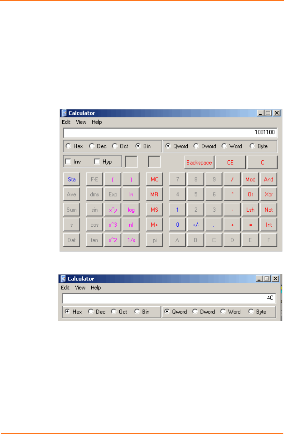
B: Binary to Hexadecimal Conversions
PremierWave EN User Guide 61
Scientific Calculator
Another simple way to convert binary to hexadecimal is to use a scientific calculator, such as
the one available on the Windows operating systems. For example:
1. On the Windows Start menu, click ProgramsAccessoriesCalculator.
2. On the View menu, select Scientific. The scientific calculator appears.
3. Click Bin (Binary), and type the number you want to convert.
4. Click Hex. The hexadecimal value appears.

PremierWave EN User Guide 62
C
C:
:
C
Co
om
mp
pl
li
ia
an
nc
ce
e
(According to ISO/IEC Guide 17050-1, 17050-2 and EN 45014)
Manufacturer’s Name & Address:
Lantronix
167 Technology Drive, Irvine, CA 92618 USA
Product Name Model: PremierWave EN Embedded Device Server
Conforms to the following standards or other normative documents:
FCC Part 15.247/15.407 Class B
RSS-210
RSS-Gen Issue 2
ICES-003 Issue 4
ETSI EN 301 489-1 V1.8.1
ETSI EN 301 489-17 V1.3.2
ETSI EN 300 328 V1.7.1
ETSI EN 301 893 V1.5.1
Manufacturer’s Contact:
Lantronix
167 Technology Drive, Irvine, CA 92618 USA
Tel: 949-453-3990
Fax: 949-450-7249

C: Compliance
PremierWave EN User Guide 63
RoHS Notice:
All Lantronix products in the following families are China RoHS-compliant and free of the following hazardous substances and
elements:
•
Lead (Pb)
•
Mercury (Hg)
•
Polybrominated biphenyls (PBB)
• Cadmium (Cd) • Hexavalent Chromium (Cr (VI)) • Polybrominated diphenyl ethers (PBDE)
•
Product Family Name
Toxic or hazardous Substances and Elements
Lead
(Pb) Mercury
(Hg) Cadmium
(Cd) Hexavalent
Chromium
(Cr (VI))
Polybrominated
biphenyls (PBB) Polybrominated diphenyl
ethers (PBDE)
UDS1100 and 2100
0
0
0
0
0
0
EDS
0
0
0
0
0
0
MSS100
0
0
0
0
0
0
IntelliBox
0
0
0
0
0
0
XPress DR & XPress-DR+
0
0
0
0
0
0
SecureBox 1101 & 2101
0
0
0
0
0
0
WiBox
0
0
0
0
0
0
UBox
0
0
0
0
0
0
MatchPort
0
0
0
0
0
0
SLC
0
0
0
0
0
0
XPort
0
0
0
0
0
0
WiPort
0
0
0
0
0
0
SLB
0
0
0
0
0
0
SLP
0
0
0
0
0
0
SCS
0
0
0
0
0
0
SLS
0
0
0
0
0
0
DSC
0
0
0
0
0
0
PremierWave
0
0
0
0
0
0
O: toxic or hazardous substance contained in all of the homogeneous materials for this part is below the limit requirement in SJ/T11363-2006.
X: toxic or hazardous substance contained in at least one of the homogeneous materials used for this part is above the limit requirement in SJ/T11363-2006.


PremierWave EN User Guide 65
E
E:
:
U
US
SB
B-
-C
CD
DC
C-
-A
AC
CM
M
D
De
ev
vi
ic
ce
e
D
Dr
ri
iv
ve
er
r
F
Fi
il
le
e
f
fo
or
r
W
Wi
in
nd
do
ow
ws
s
H
Ho
os
st
ts
s
The following file may be used to enable Windows to recognize the USB-CDC-ACM
connection to the PremierWave EN's USB Device port. This file is copied verbatim from the
Linux distribution (2.6.36+) at Documentation/usb/linux-cdc-acm.inf.
Place this file on the Windows host somewhere. When Windows prompts for a device driver
for the USB connection, point it to this file.
; Windows USB CDC ACM Setup File
; Based on INF template which was:
; Copyright (c) 2000 Microsoft Corporation
; Copyright (c) 2007 Microchip Technology Inc.
; likely to be covered by the MLPL as found at:
; <http://msdn.microsoft.com/en-us/cc300389.aspx#MLPL>.
; For use only on Windows operating systems.
[Version]
Signature="$Windows NT$"
Class=Ports
ClassGuid={4D36E978-E325-11CE-BFC1-08002BE10318}
Provider=%Linux%
DriverVer=11/15/2007,5.1.2600.0
[Manufacturer]
%Linux%=DeviceList, NTamd64
[DestinationDirs]
DefaultDestDir=12
;------------------------------------------------------------------------------
; Windows 2000/XP/Vista-32bit Sections
;------------------------------------------------------------------------------
[DriverInstall.nt]
include=mdmcpq.inf
CopyFiles=DriverCopyFiles.nt
AddReg=DriverInstall.nt.AddReg
[DriverCopyFiles.nt]
usbser.sys,,,0x20
[DriverInstall.nt.AddReg]
HKR,,DevLoader,,*ntkern
HKR,,NTMPDriver,,USBSER.sys
HKR,,EnumPropPages32,,"MsPorts.dll,SerialPortPropPageProvider"
[DriverInstall.nt.Services]
AddService=usbser, 0x00000002, DriverService.nt
[DriverService.nt]
DisplayName=%SERVICE%
ServiceType=1
StartType=3
ErrorControl=1
ServiceBinary=%12%\USBSER.sys
;------------------------------------------------------------------------------
; Vista-64bit Sections
;------------------------------------------------------------------------------
[DriverInstall.NTamd64]
include=mdmcpq.inf
CopyFiles=DriverCopyFiles.NTamd64
AddReg=DriverInstall.NTamd64.AddReg
[DriverCopyFiles.NTamd64]
USBSER.sys,,,0x20
[DriverInstall.NTamd64.AddReg]
HKR,,DevLoader,,*ntkern
HKR,,NTMPDriver,,USBSER.sys
HKR,,EnumPropPages32,,"MsPorts.dll,SerialPortPropPageProvider"
[DriverInstall.NTamd64.Services]
AddService=usbser, 0x00000002, DriverService.NTamd64

E: USB-CDC-ACM Device Driver File for Windows Hosts
PremierWave EN User Guide 66
[DriverService.NTamd64]
DisplayName=%SERVICE%
ServiceType=1
StartType=3
ErrorControl=1
ServiceBinary=%12%\USBSER.sys
;------------------------------------------------------------------------------
; Vendor and Product ID Definitions
;------------------------------------------------------------------------------
; When developing your USB device, the VID and PID used in the PC side
; application program and the firmware on the microcontroller must match.
; Modify the below line to use your VID and PID. Use the format as shown
; below.
; Note: One INF file can be used for multiple devices with different
; VID and PIDs. For each supported device, append
; ",USB\VID_xxxx&PID_yyyy" to the end of the line.
;------------------------------------------------------------------------------
[SourceDisksFiles]
[SourceDisksNames]
[DeviceList]
%DESCRIPTION%=DriverInstall, USB\VID_0525&PID_A4A7, USB\VID_0525&PID_A4AB&MI_02
[DeviceList.NTamd64]
%DESCRIPTION%=DriverInstall, USB\VID_0525&PID_A4A7, USB\VID_0525&PID_A4AB&MI_02
;------------------------------------------------------------------------------
; String Definitions
;------------------------------------------------------------------------------
;Modify these strings to customize your device
;------------------------------------------------------------------------------
[Strings]
Linux = "Linux Developer Community"
DESCRIPTION = "Gadget Serial"
SERVICE = "USB RS-232 Emulation Driver"

PremierWave EN User Guide 67
I
In
nd
de
ex
x
A
Accessing PremierWave EN, 16
Additional Documentation, 11
Address
Ethernet, 14
Hardware, 14, 15
IP, 14
MAC, 14, 15
Applications, 12
B
Bar code, 15
Binary to hexadecimal conversions, 60
C
Command Line Interface Settings, 49
Configuration methods, 13
CPM, 37
D
default server port numbers, 14
Device Details Summary, 17
diagnostic toolset, 13
Diagnostics, 46
DNS Lookup, 47
IP Sockets, 46
Memory, 47
Ping, 46
Processes, 47
Traceroute, 46
Diagnostics Settings, 44
DNS Configuration, 40
E
Ethernet address, 14
F
File Display Commands, 44
File System
Configuration, 44
File Transfer Commands, 45
Firmware, 58
FreeRadius, 57
H
Hardware Address, 14, 15
I
IP Address, 14
K
Key Features, 12
L
Label, 15
Lantronix Discovery Protocol, 14
Line Settings, 31, 32
locating a PremierWave EN unit, 16
M
MAC Address, 14, 15
Maintenance Settings, 9, 44
O
OpenSSL, 56
P
Part number, 15
Port Numbers, 14
Port Numbers, 14
Ports
Serial and Telnet, 13
Product Information Label, 15
Protocol Support, 13
Q
Query Port, 45
S
Secure Sockets Layer, 55
Security
in Detail, 9, 55
Settings, 9, 41
SSL
Certificates, 55
Settings, 41
Utilities, 56
Steel Belted Radius, 56
Summary of Chapters, 9
Syslog Configuration, 40
T
Technical Support, 59
Telnet port, 13

Index
PremierWave EN User Guide 68
Troubleshooting Capabilities, 13
Tunnel Settings
Accept Mode, 33
Connect Mode, 35
Packing Mode, 36
Tunneling
Accept Mode, 53
Connect Mode, 53
Packing Mode, 54
U
Updating Firmware, 58
W
WLAN
Settings
Network 1 Ethernet Link, 21, 22, 24, 25,
26, 27, 28
X
XML
Export Configuration, 51
Import System Configuration, 52
XML, 14
XML Configuration, 51