lantronix PWXCHSPA PremierWave XC HSPA+ User Manual PWXC HSPA BP UG2
lantronix PremierWave XC HSPA+ PWXC HSPA BP UG2
UserManual.wiki
>
lantronix
>
PWXCHSPA User Manual
User Manual
Navigation menu
Upload a User Manual
Namespaces
Wiki Guide
HTML
PDF
Info
Views
User Manual
Discussion / Help
Navigation

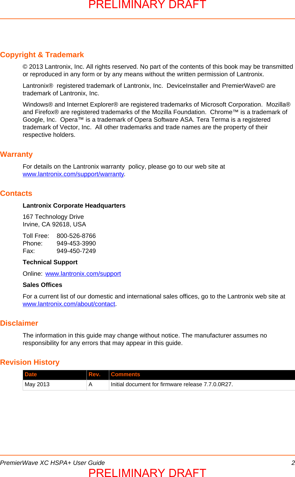
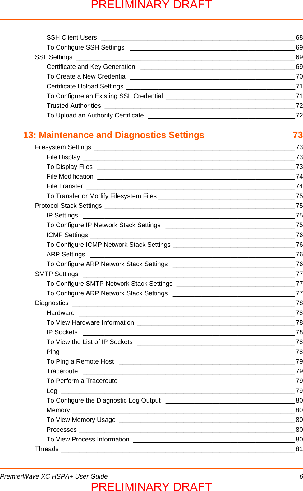
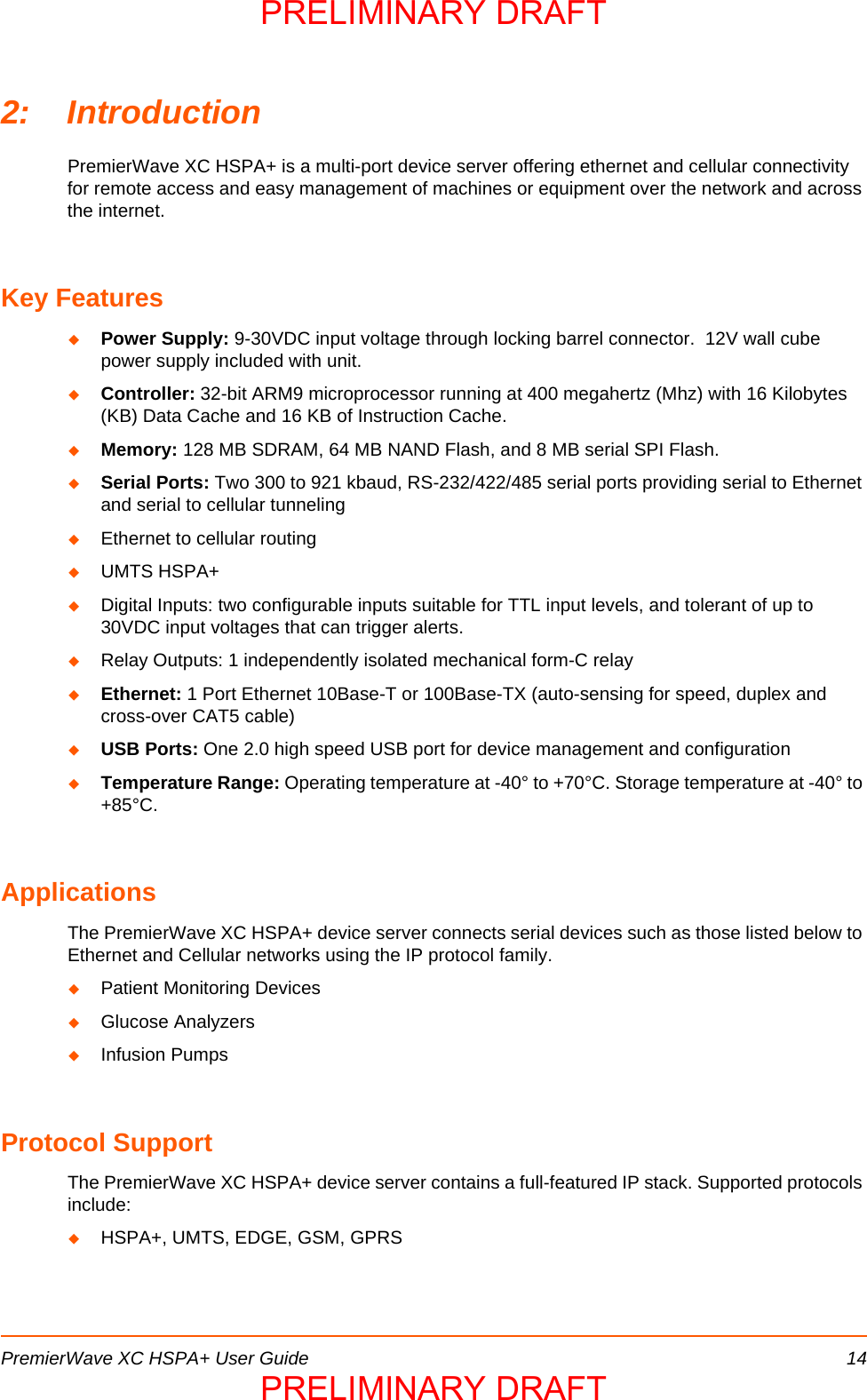
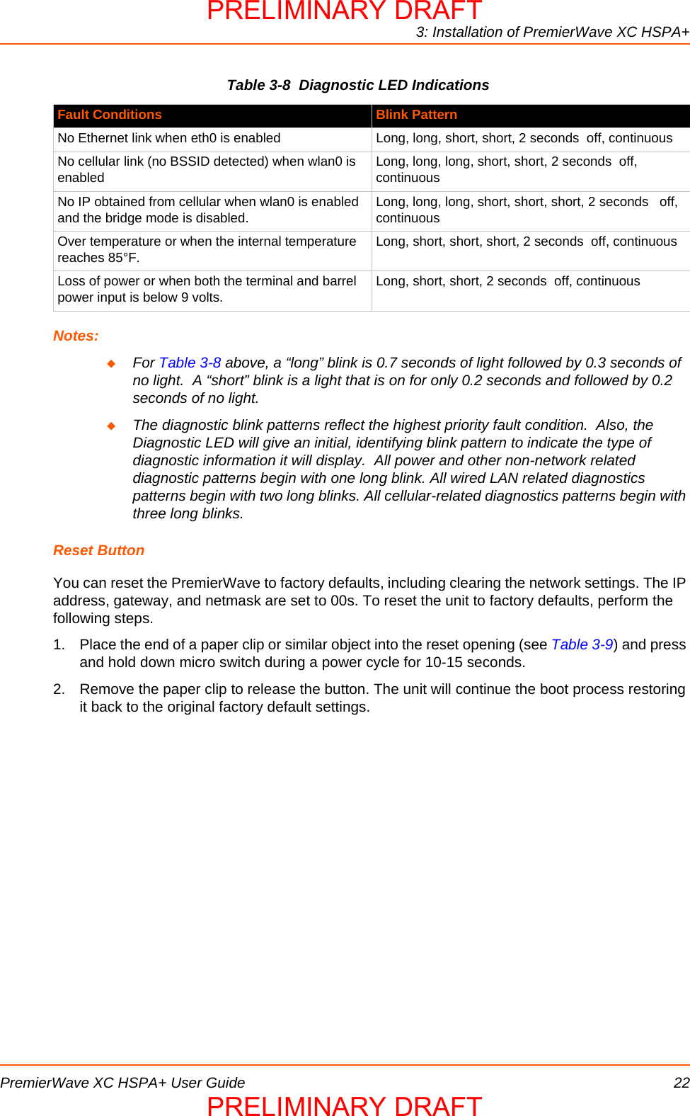

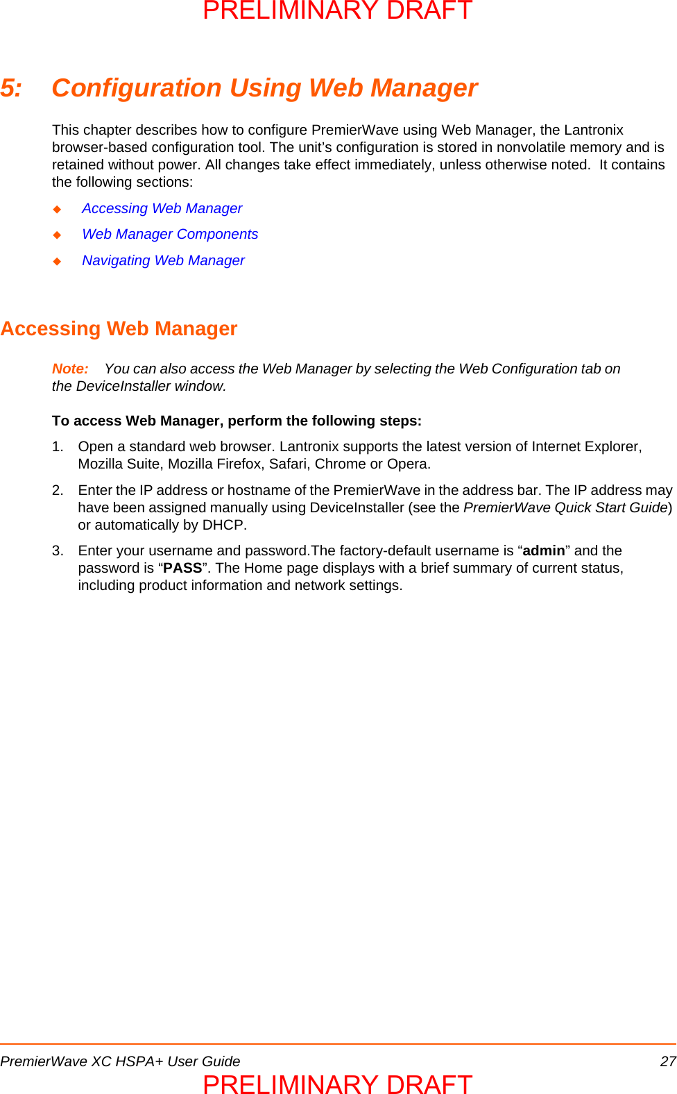
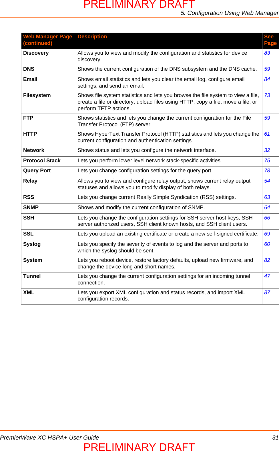
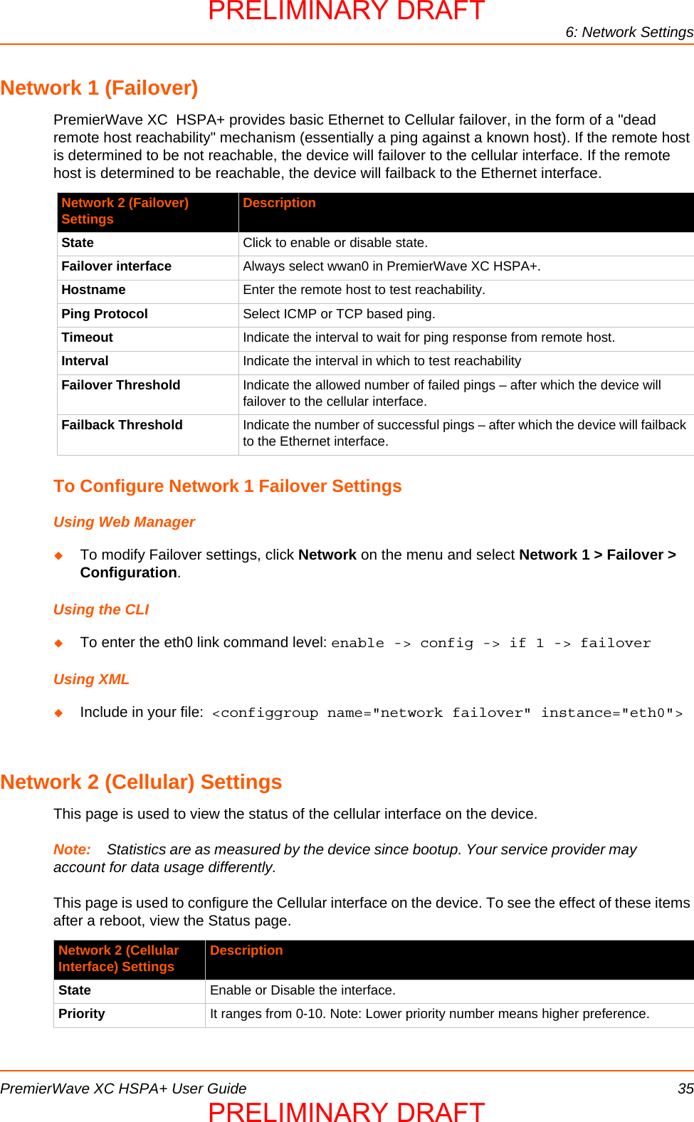
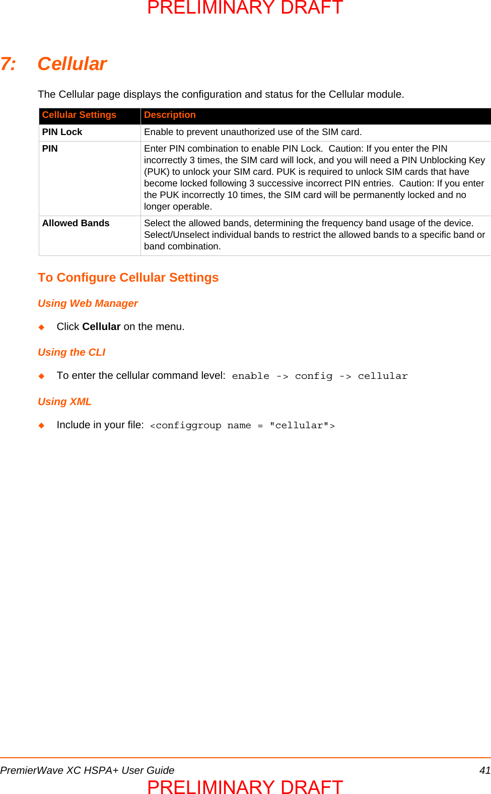
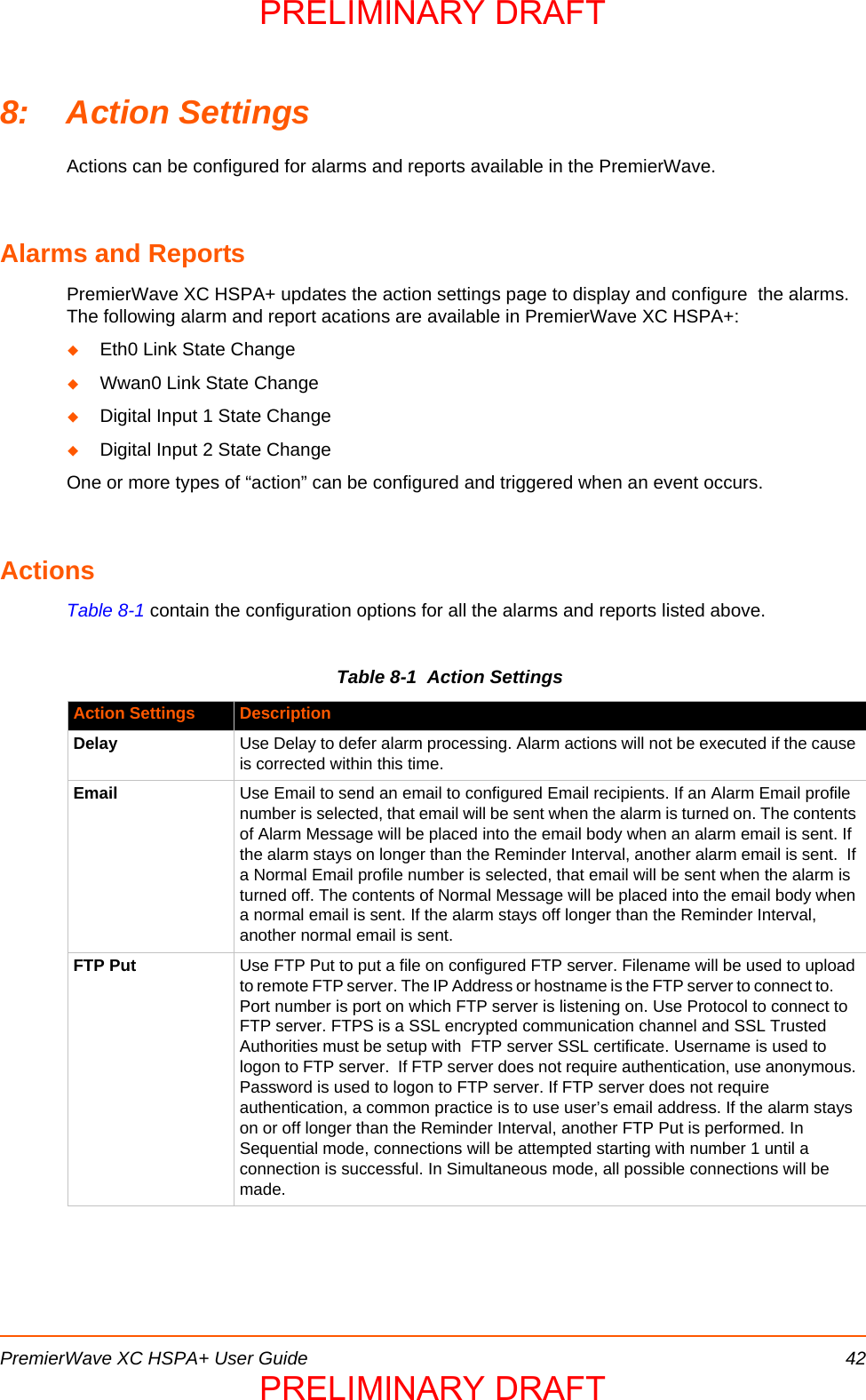
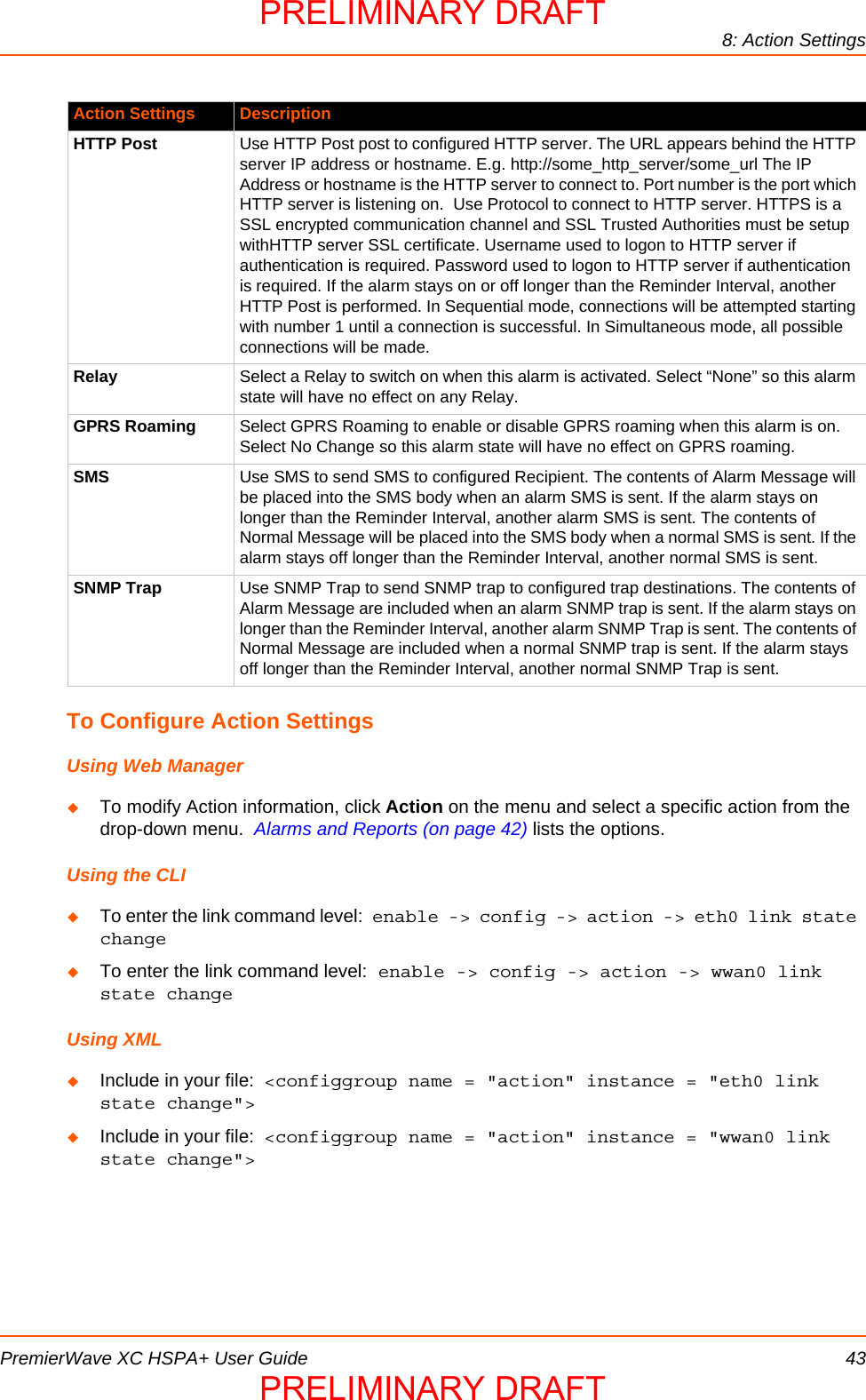
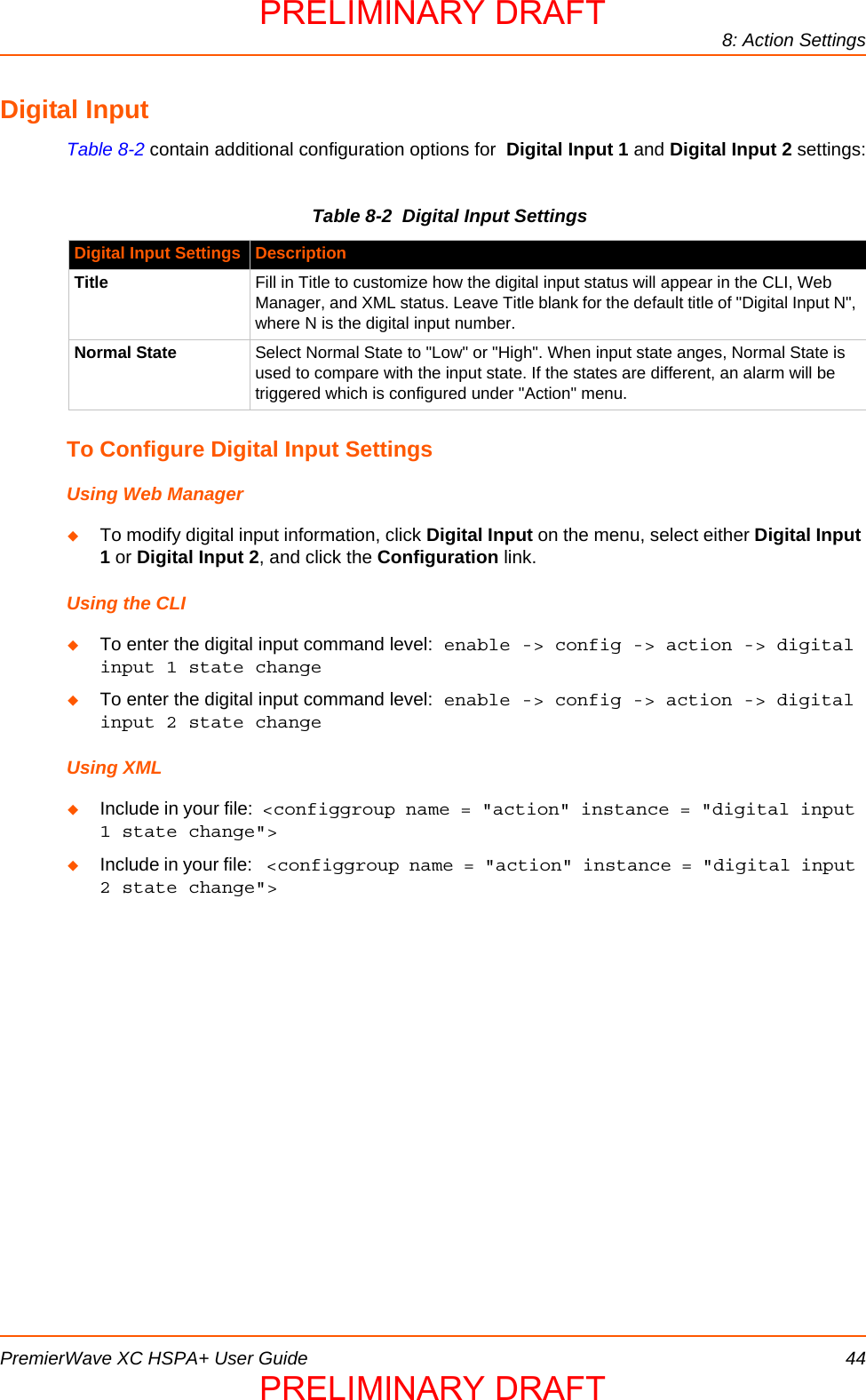
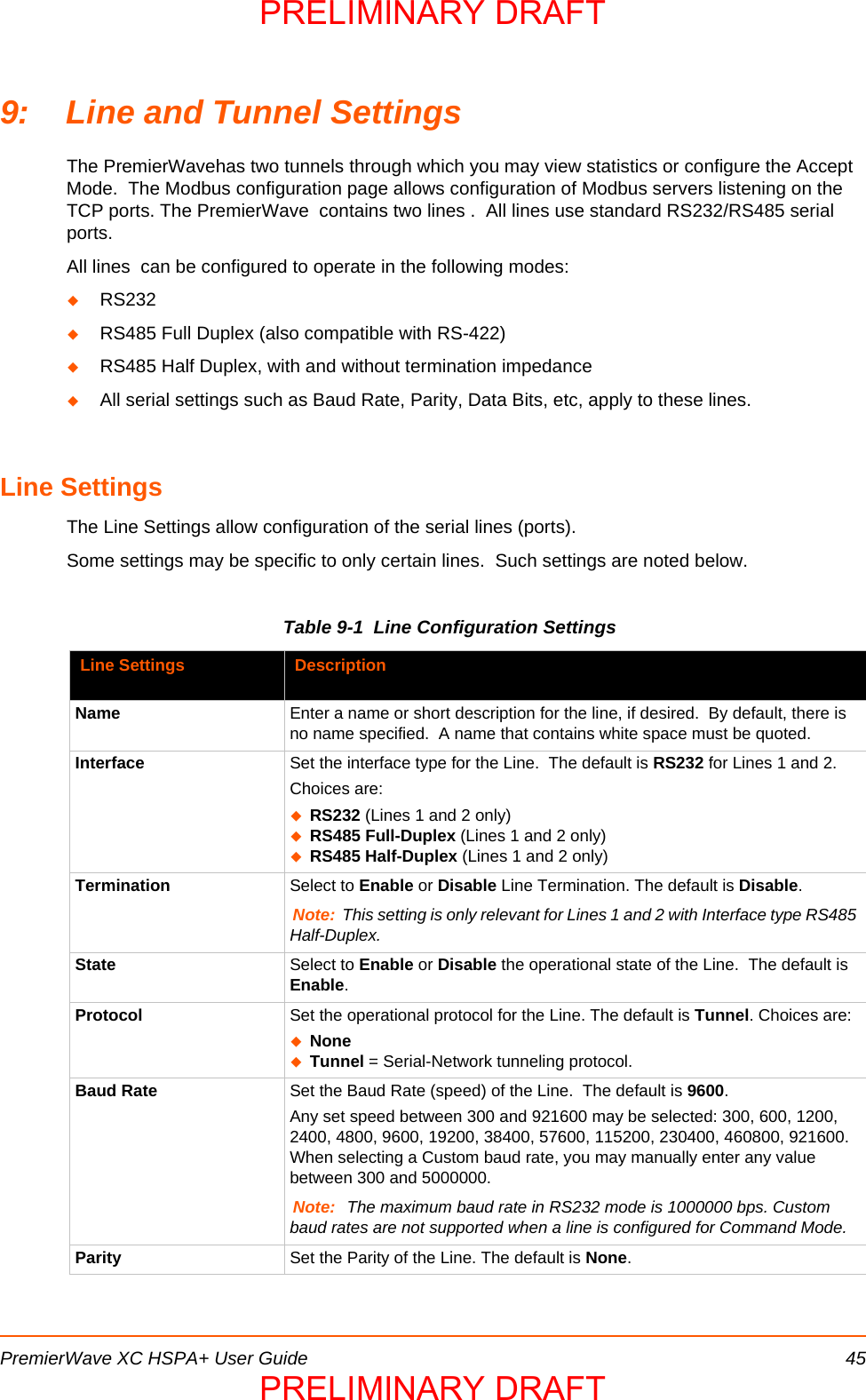
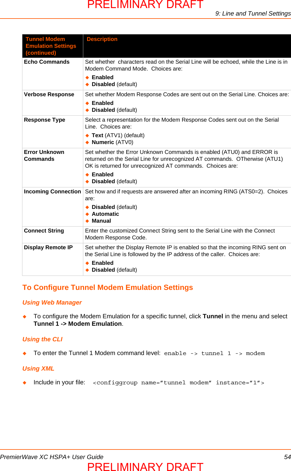
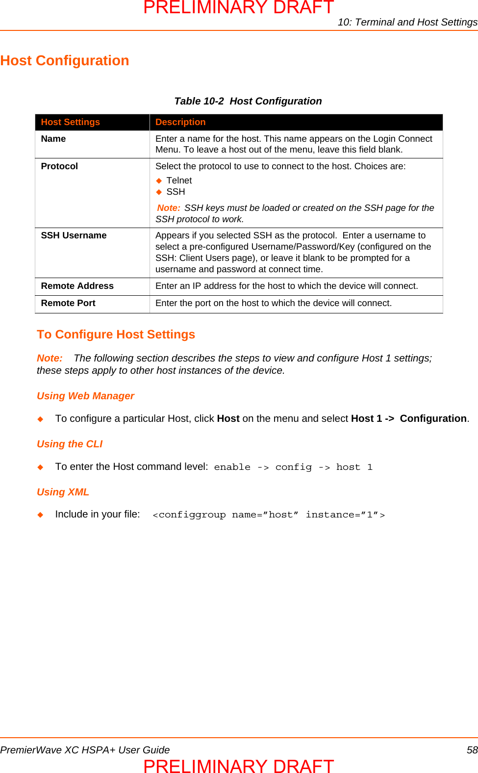
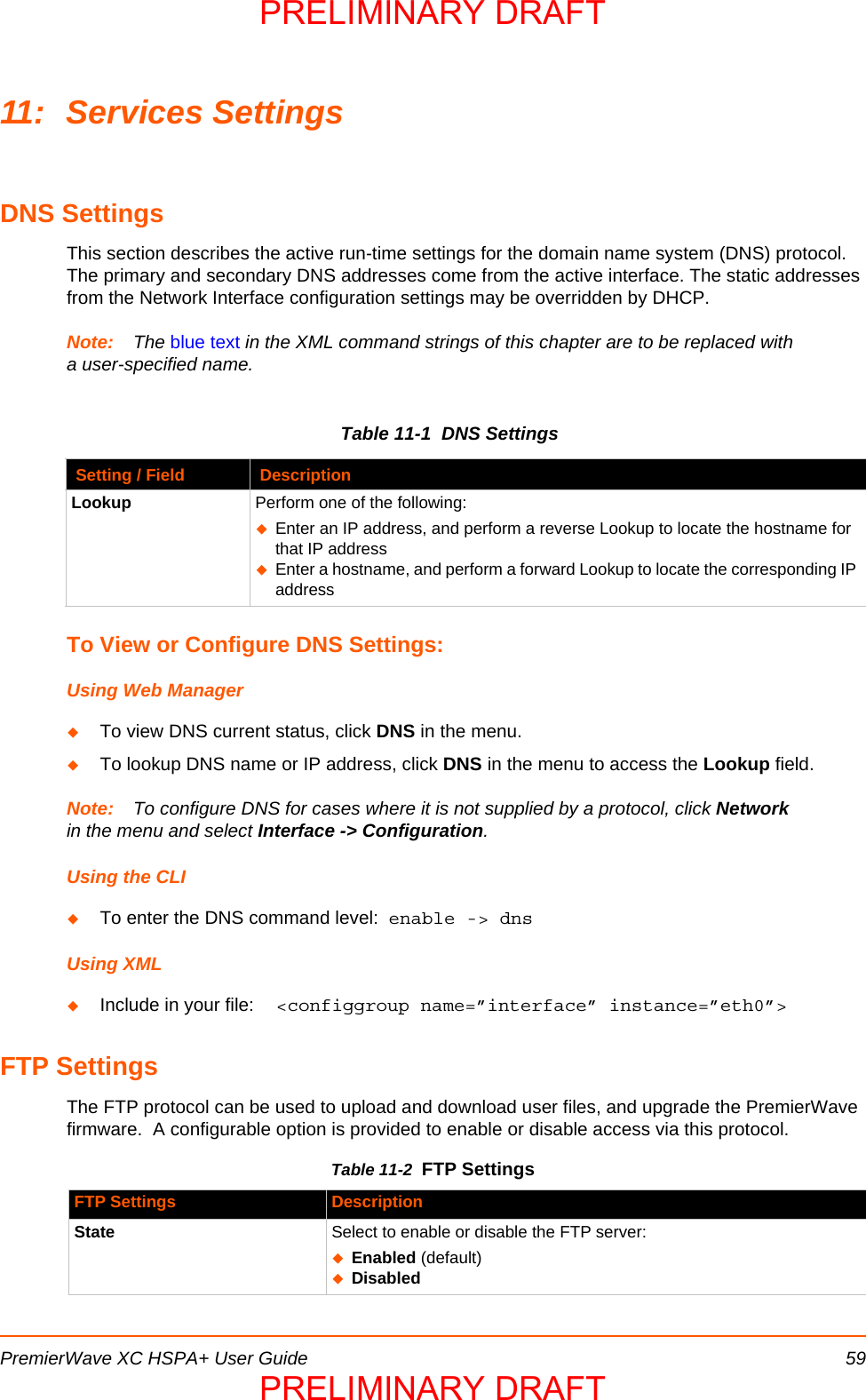
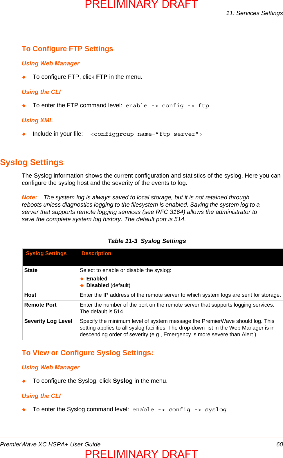
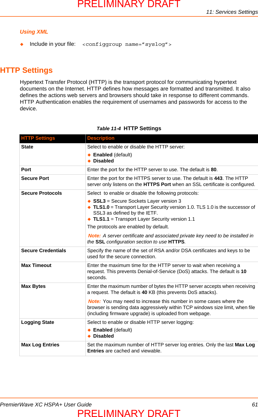
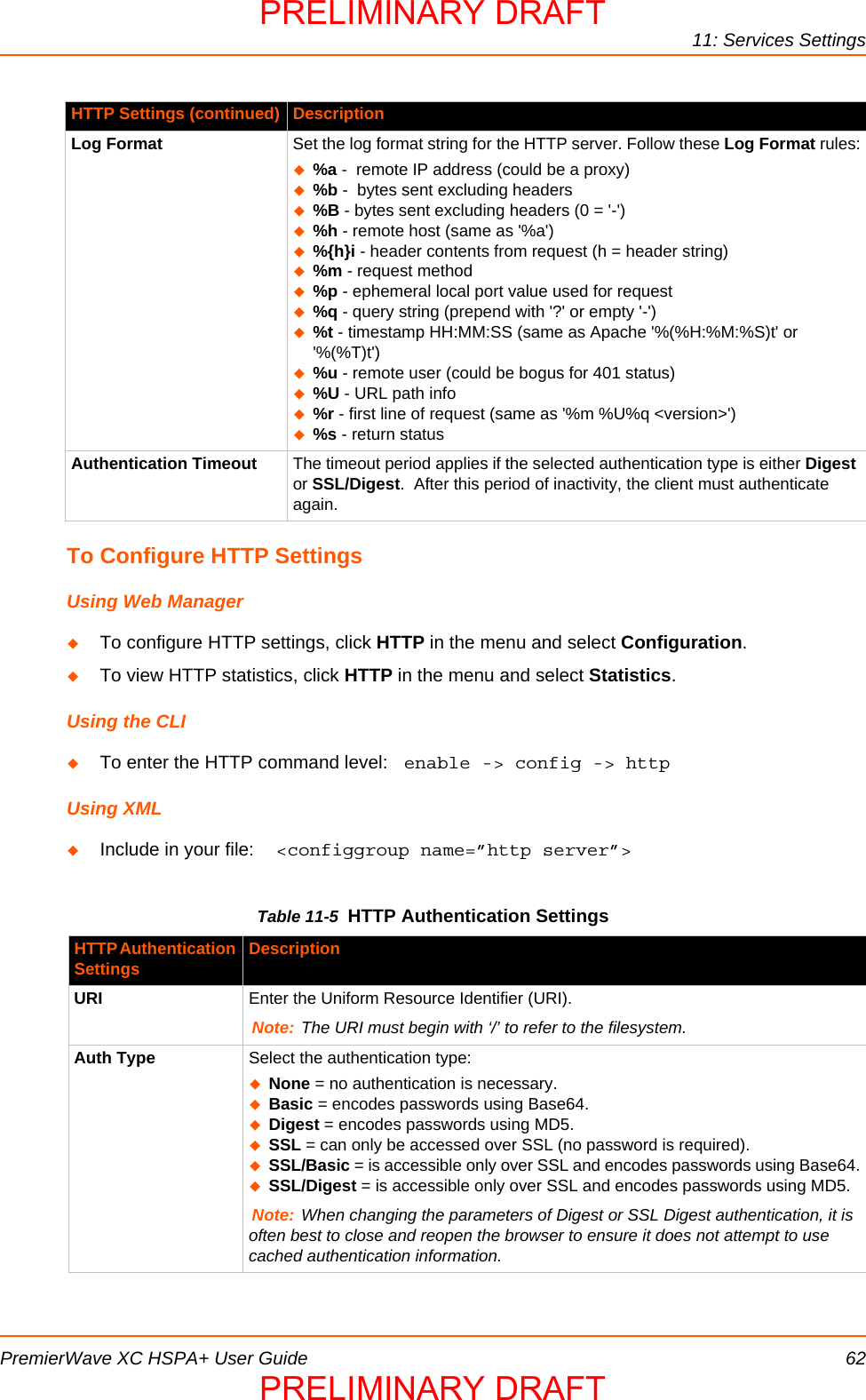
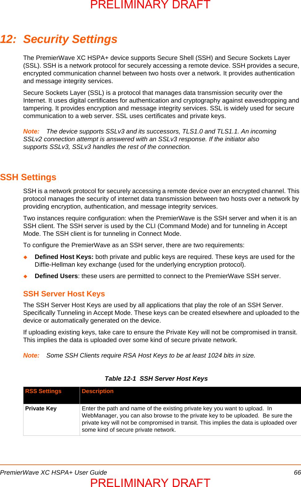
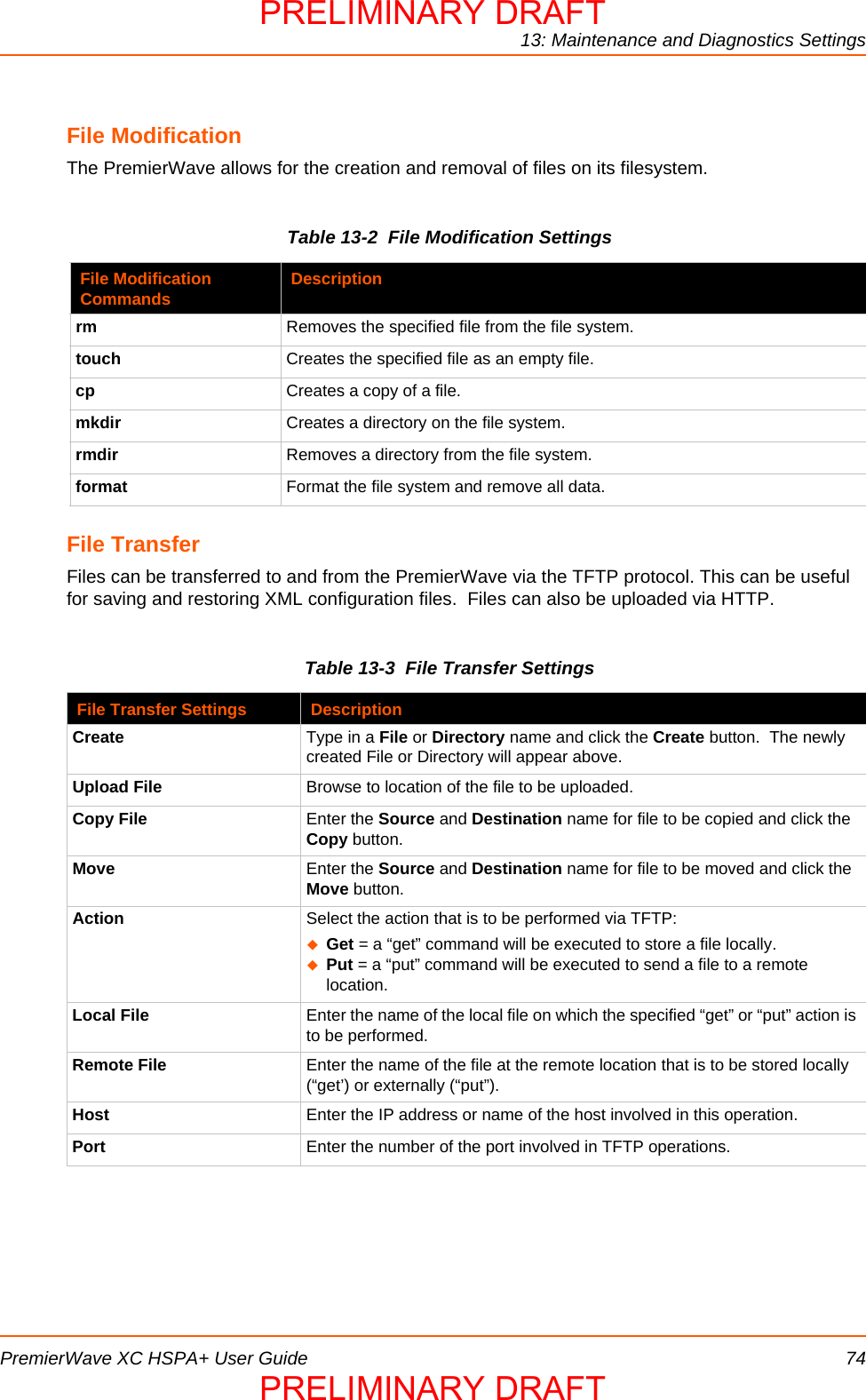
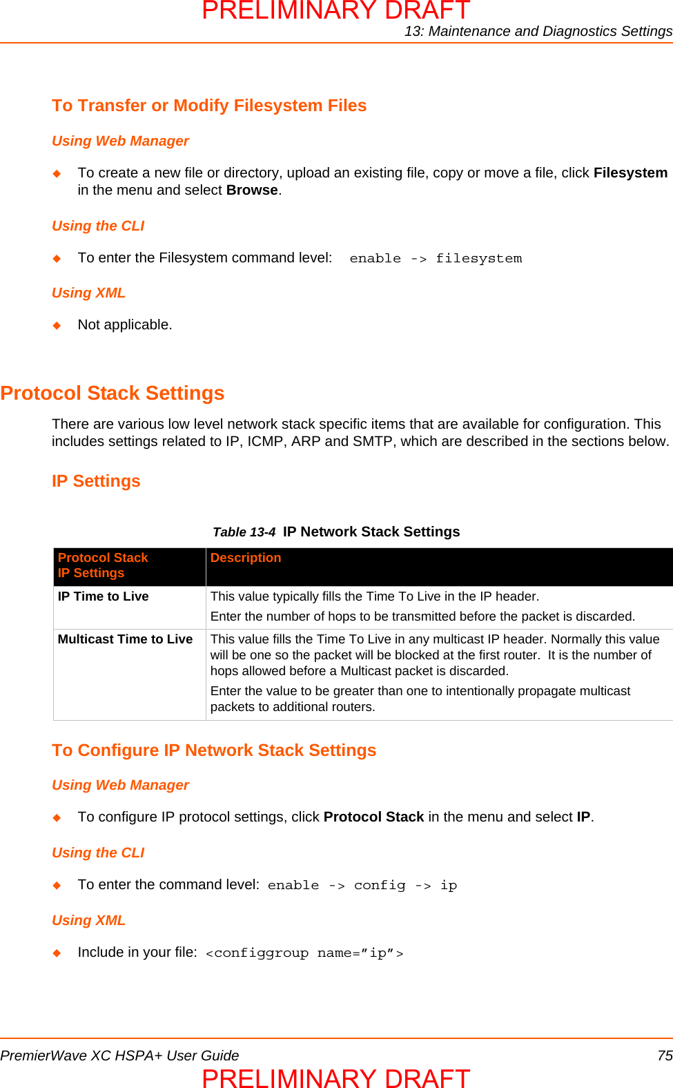
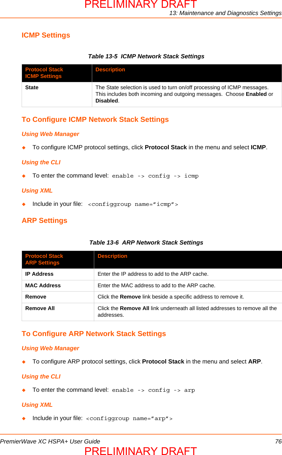
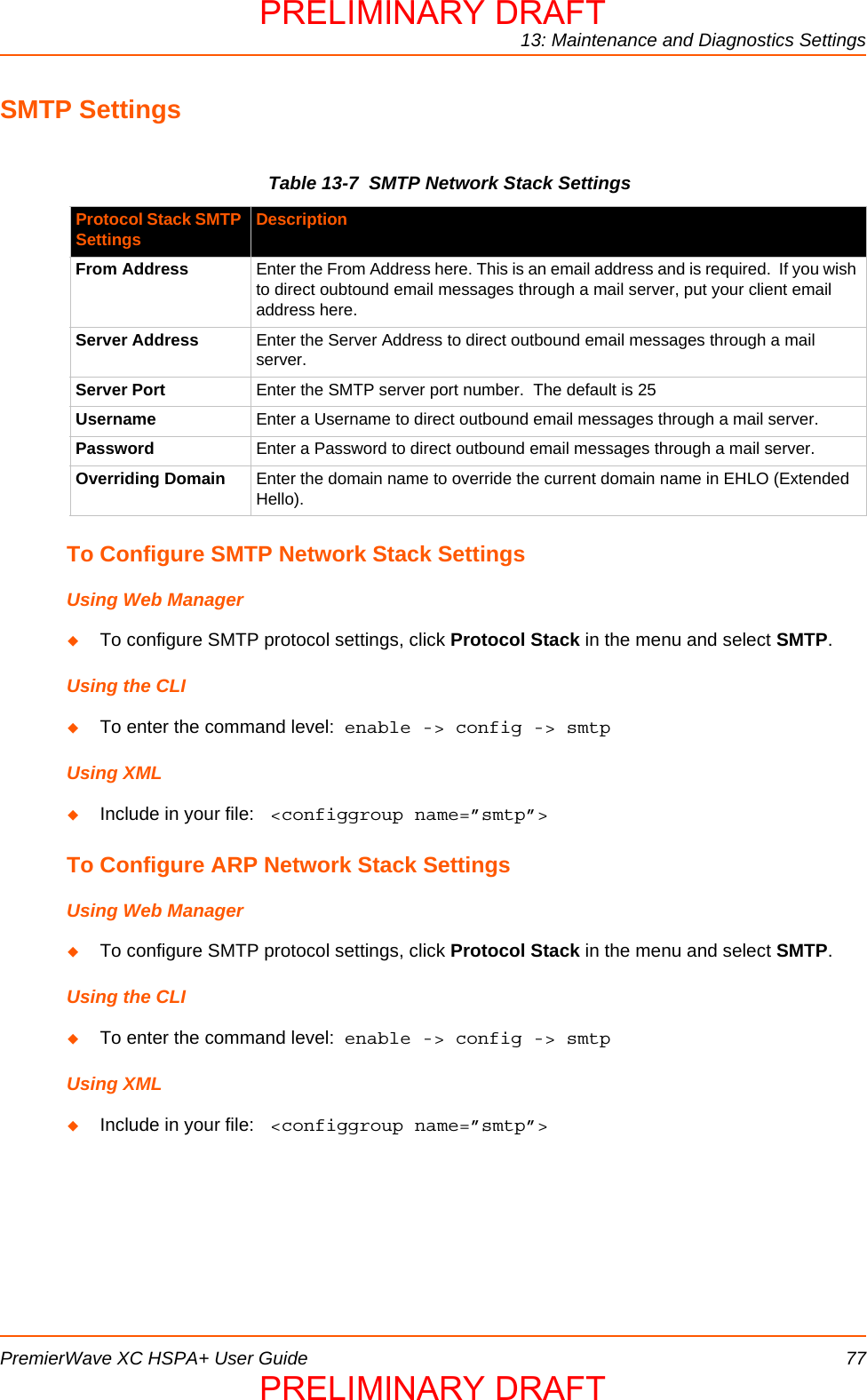
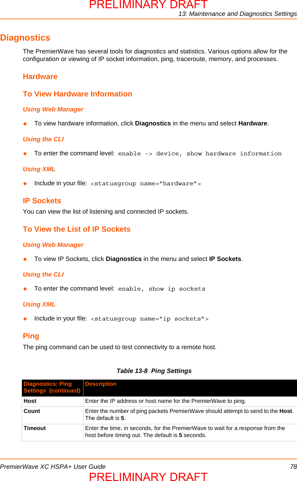
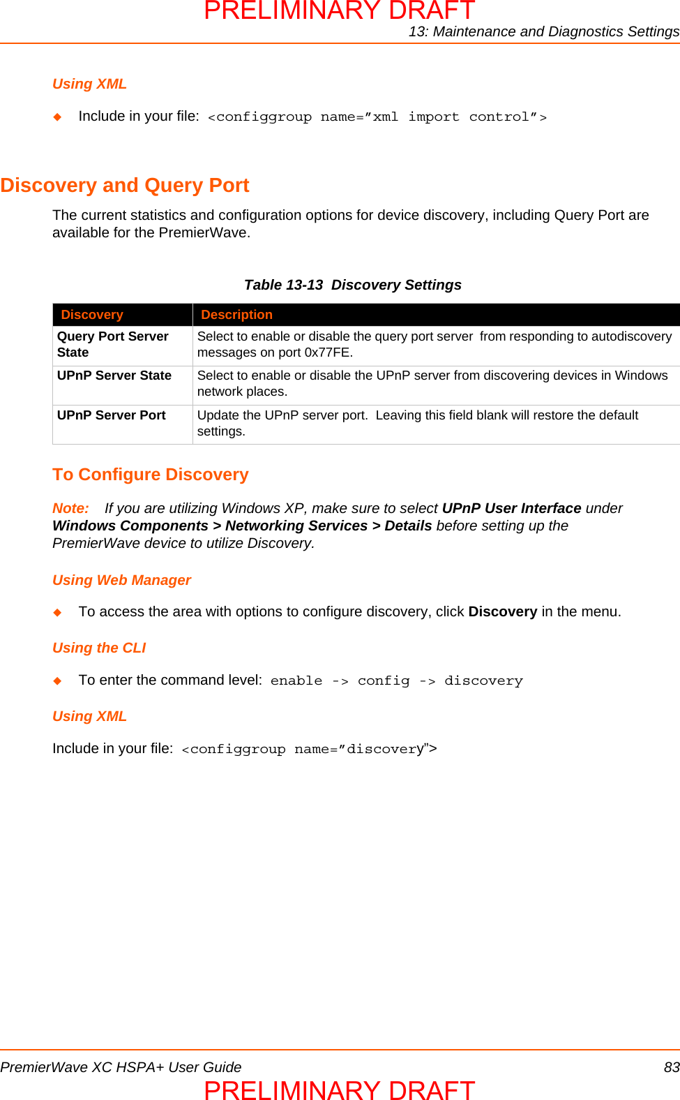
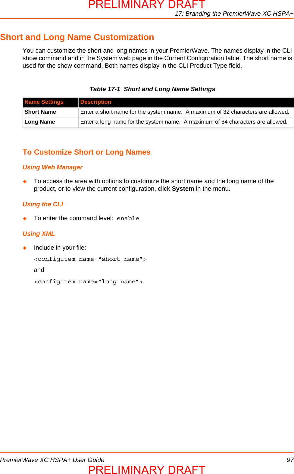
![6: Network SettingsPremierWave XC HSPA+ User Guide 38To Configure Gateway WAN SettingsUsing Web ManagerTo modify gateway WAN information, click Gateway on the menu and select Configuration > WAN.Using the CLITo enter the gateway command level: enable -> config -> gatewayUsing XMLInclude in your file: <configgroup name="gateway"> <configitem name="wan">Port ForwardingPort forwarding allows remote computers (for example, computers on the Internet) to connect to a specific computer or service within a private local-area network (LAN). This functionality will not work if the cellular provider uses NAT.Table 6-4 Port Forwarding Rules ListTable 6-5 Adding a New Port Forwarding RuleTo Configure Gateway Port Forwarding SettingsUsing Web ManagerTo modify gateway port forwarding information, click Gateway on the menu and select Configuration > Port Forwarding.Port Forwarding Rule DescriptionEnabled Enables the port forwarding rule.Delete Deletes the port forwarding rule.Name User friendly name for the rule. Click on the [Edit] icon to make changes.Port or Port Range Port or Port range for the rule.Protocol Protocols for the rule: TCP, UDP, or Both.IP Address Target for the port forwarding rule.Adding New Port Forwarding Rule SettingsDescriptionName User Friendly name for the rule {optional)Start Port Starting port numberEnd Port End port number (optional). If start port and end port are same it assumes a single port. If start port and end port are not the same – it is a port range.Protocol Protocols for the rule. TCP, UDP, or BothIP Address Target for the port forwarding rule.PRELIMINARY DRAFTPRELIMINARY DRAFT](https://usermanual.wiki/lantronix/PWXCHSPA/User-Guide-1954943-Page-38.png)
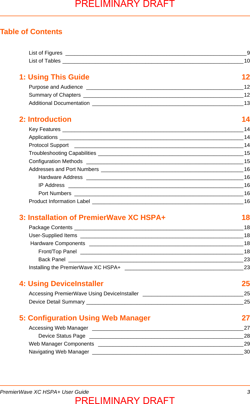
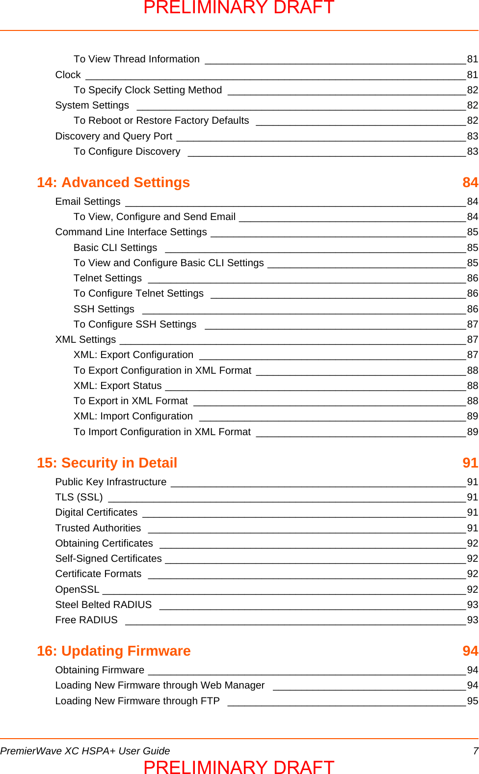
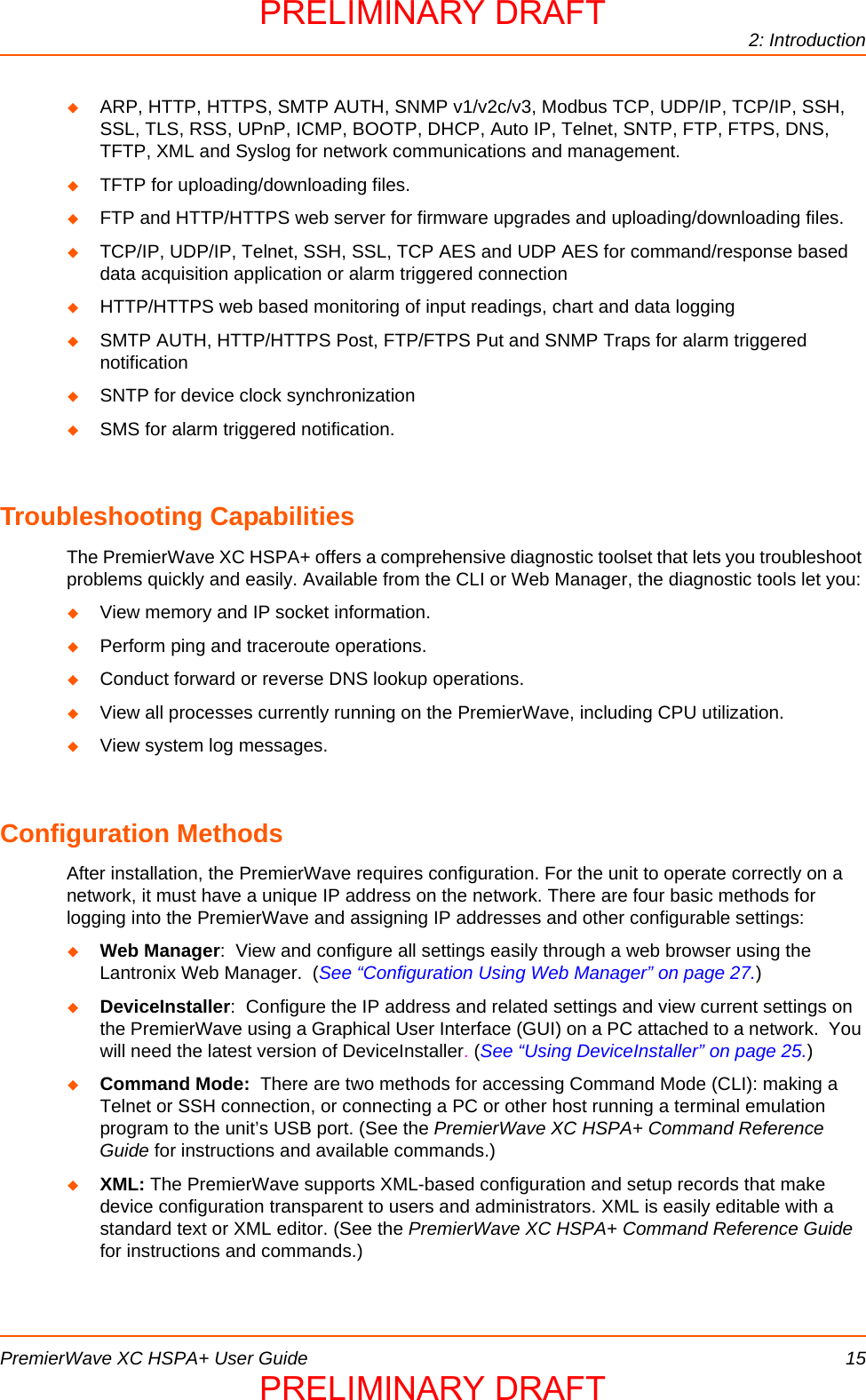
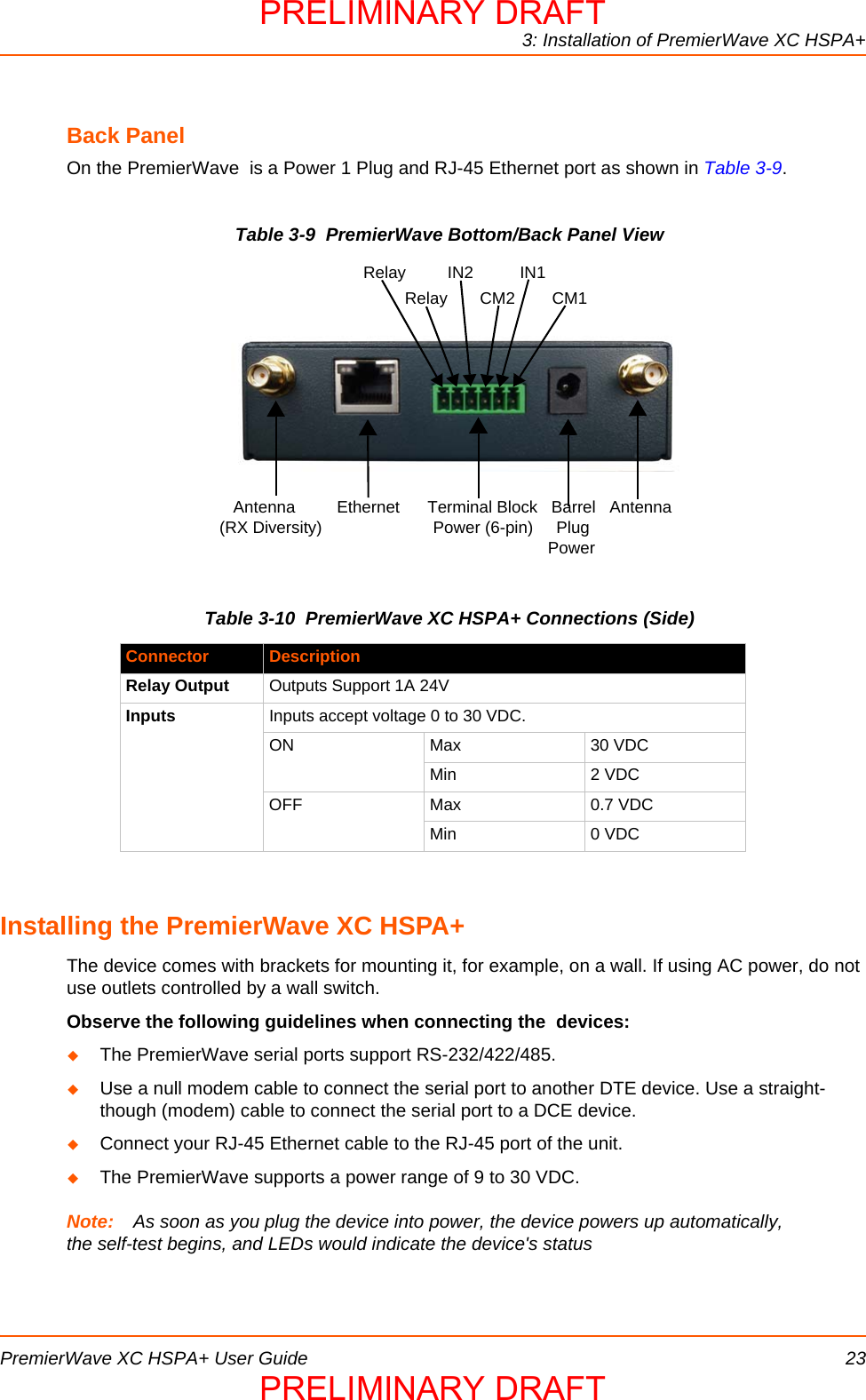
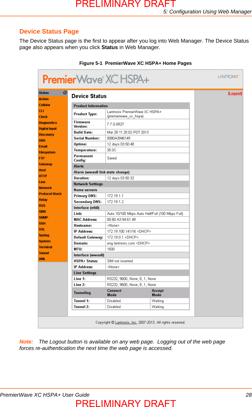
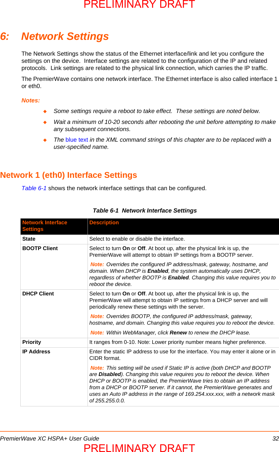
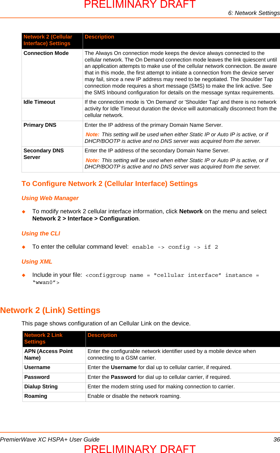
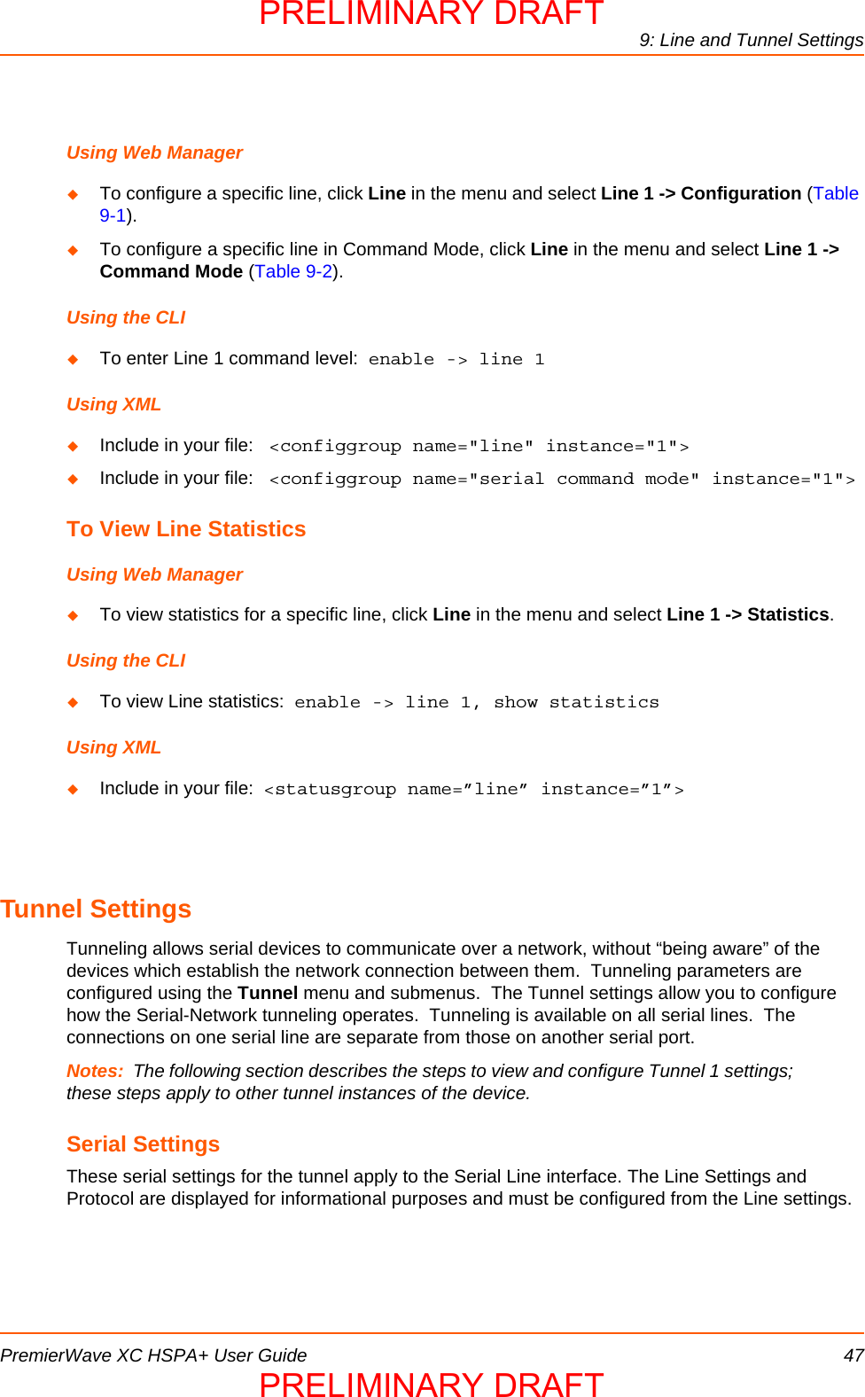
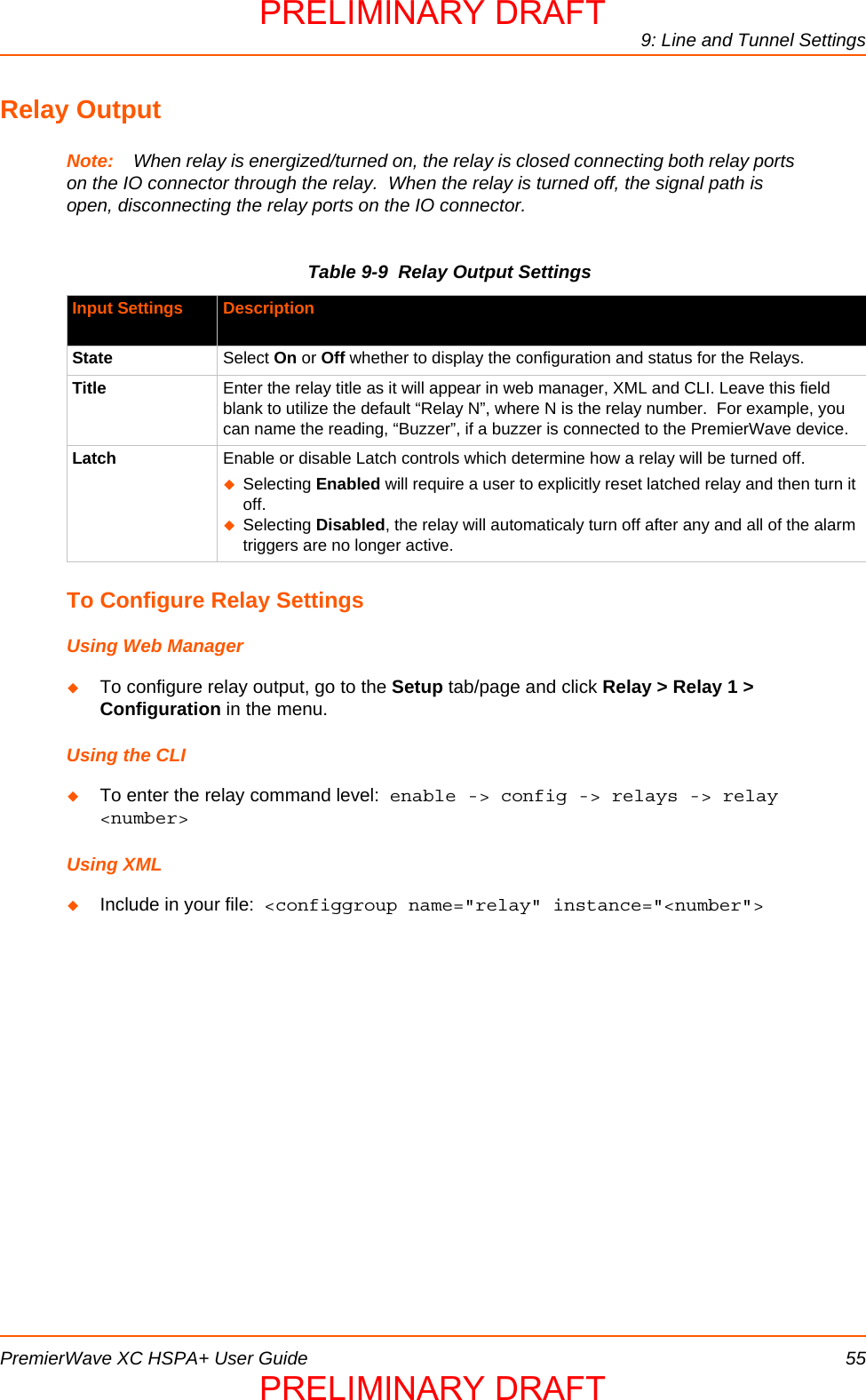
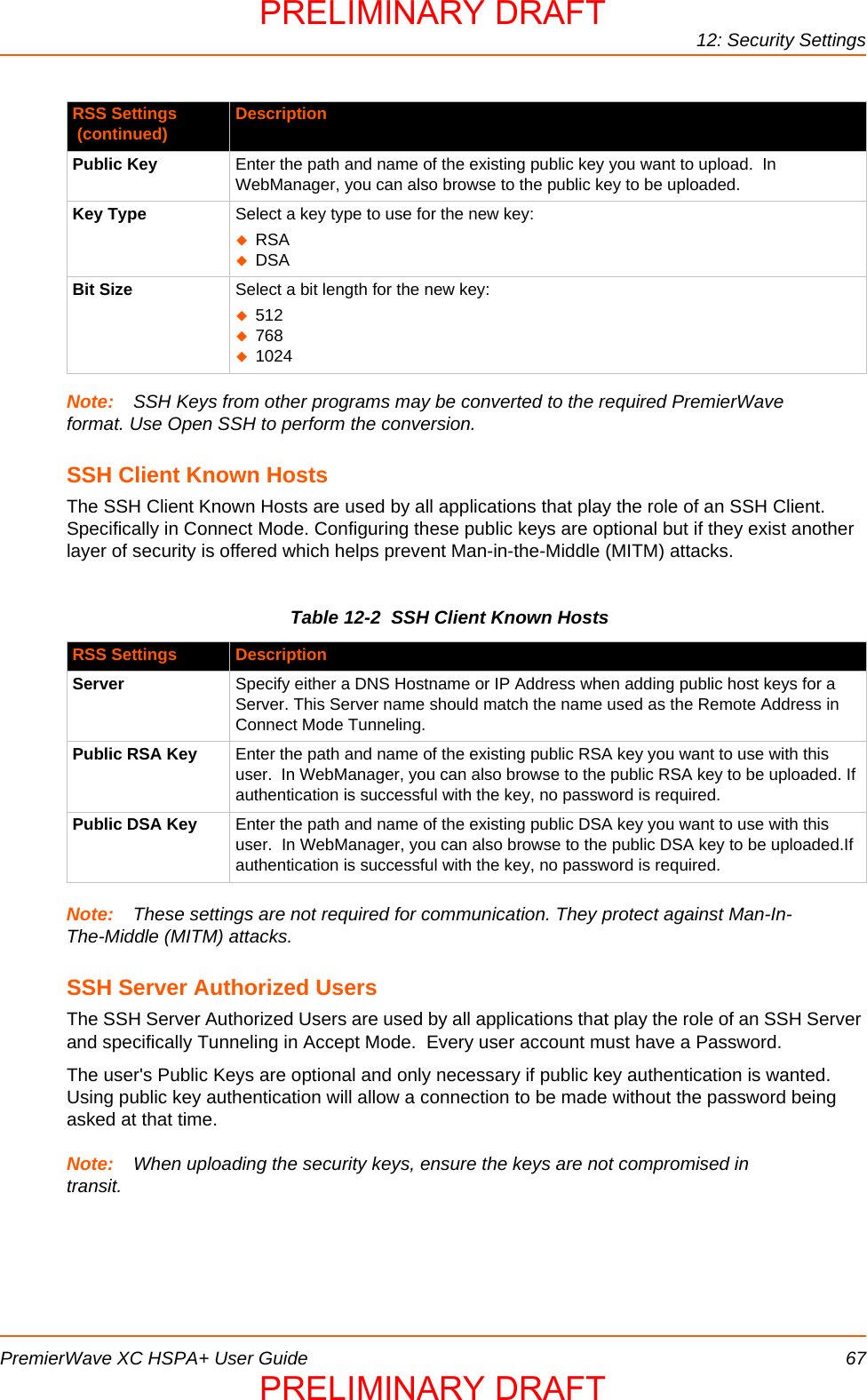
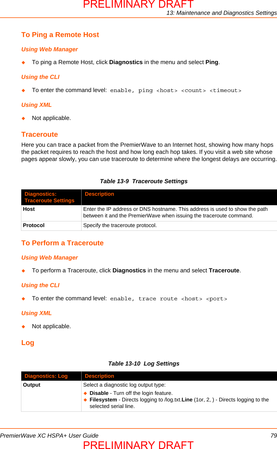
![6: Network SettingsPremierWave XC HSPA+ User Guide 39Using the CLITo enter the gateway command level: enable -> config -> gateway -> port forwarding rule <number>Using XMLInclude in your file: <configgroup name="gateway"> <configitem name="port forwarding" instance="<number>">Static RoutesAllows the user to add routes to the device routing table.Table 6-6 Adding a New Static RouteTo Configure Gateway Static Route SettingsUsing Web ManagerTo modify gateway static route information, click Gateway on the menu and select Configuration > Static Routes.Using the CLITo enter the gateway command level: enable -> config -> gateway -> static route <number>Using XMLInclude in your file: <configgroup name ="gateway"> <configitem name="static routes" instance="<number>">Static Route Settings DescriptionEnabled Enables the static routeDelete Deletes the static routeName User friendly name for the route. Click on the [Edit] icon to make changes.Route Network or Host for the routeApplied If the route was successfully applied. Routing table updates require a reboot and route needs to be valid as per other device configurables.Adding New Static Route Settings DescriptionName User friendly name for the routeNetwork Network or Host for the routeGateway Gateway for the routeInterface Interface for the routeMetric Priority for the route. Lower metric means higher priority.PRELIMINARY DRAFTPRELIMINARY DRAFT](https://usermanual.wiki/lantronix/PWXCHSPA/User-Guide-1954943-Page-39.png)
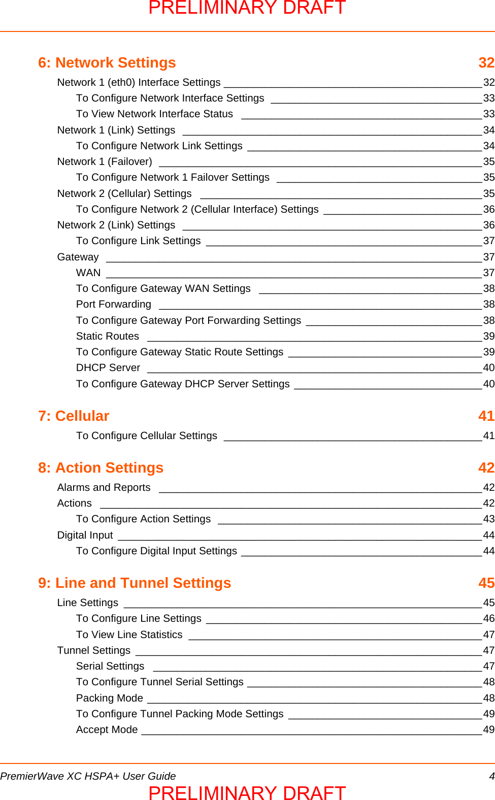
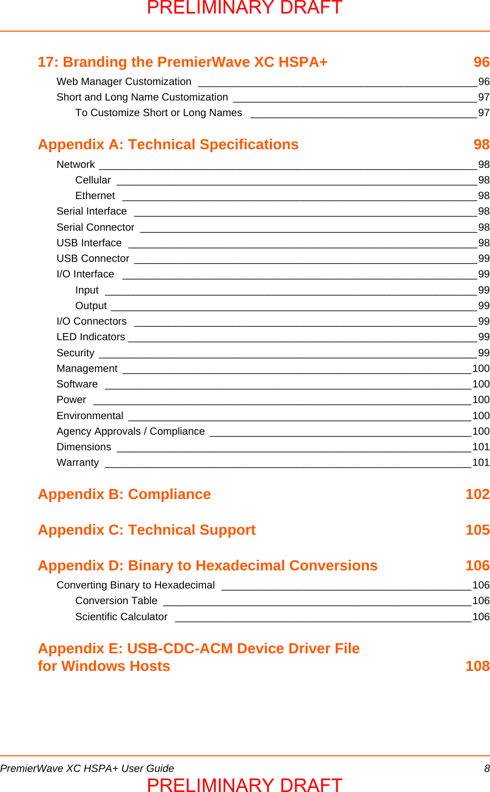
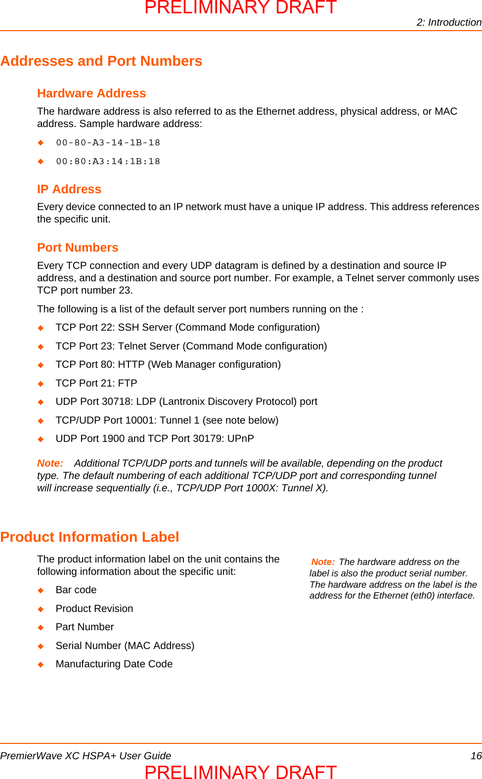
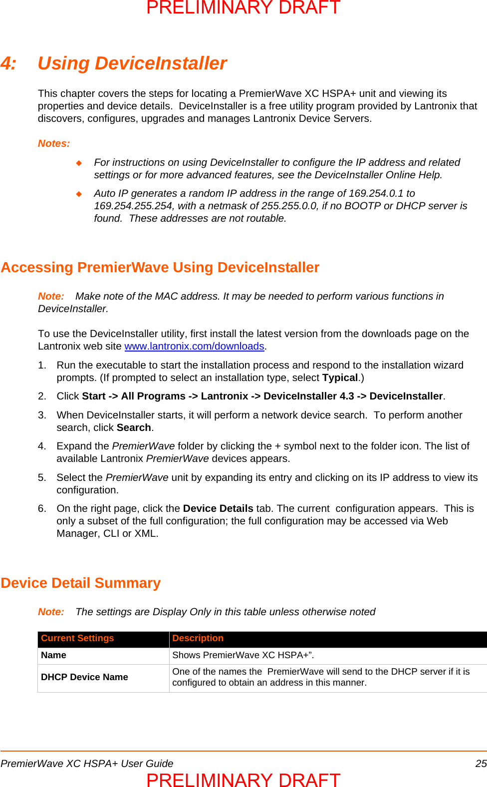
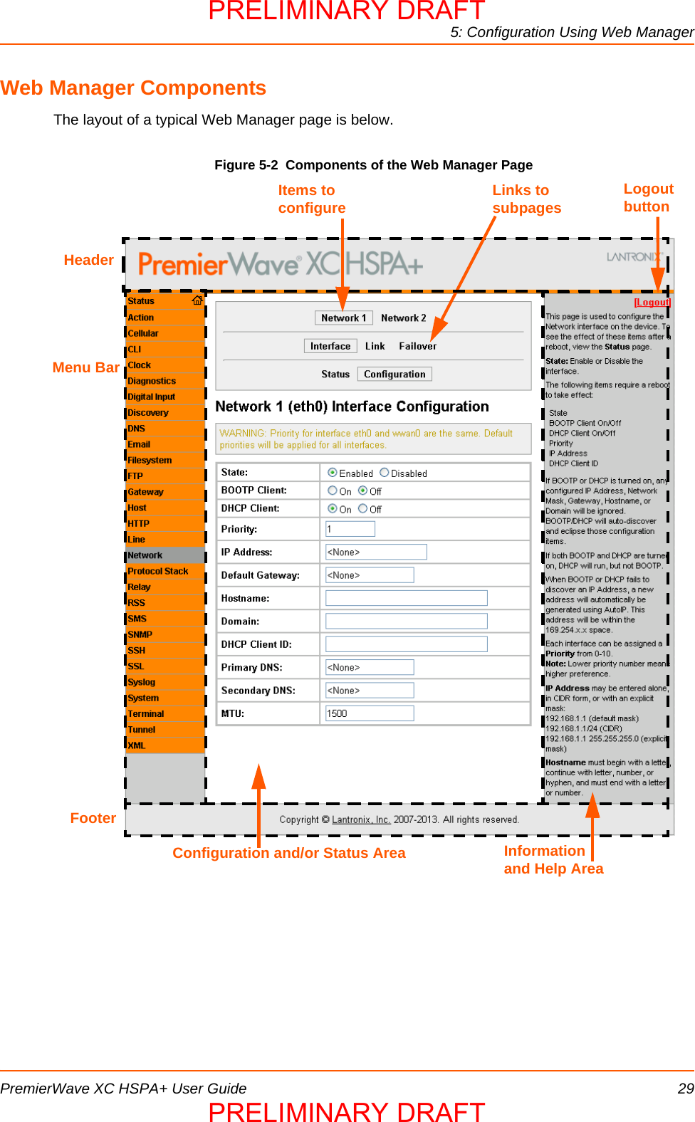
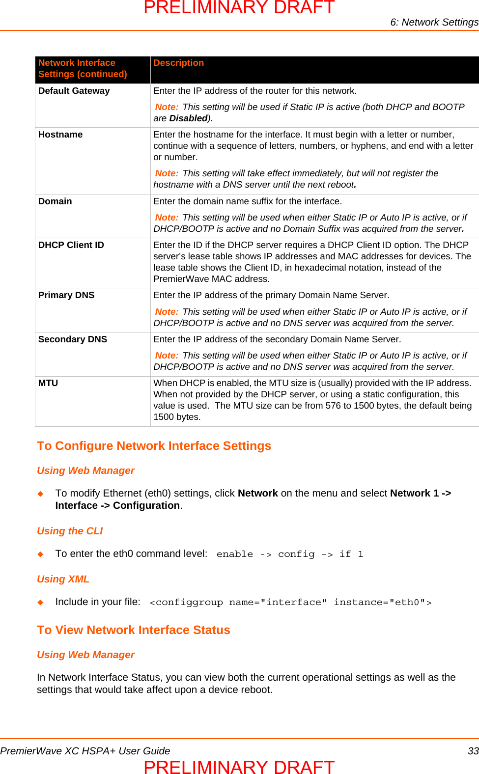
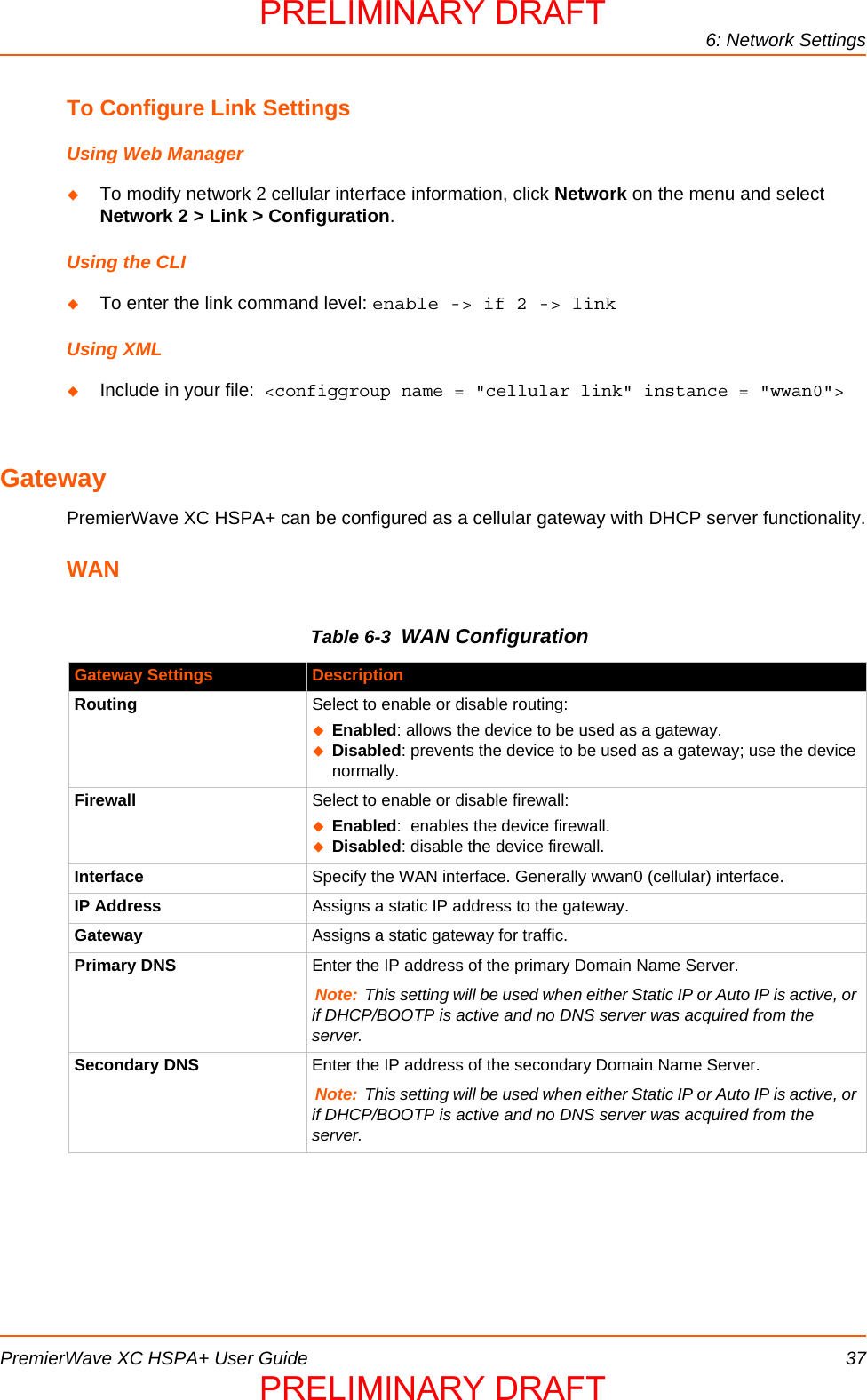
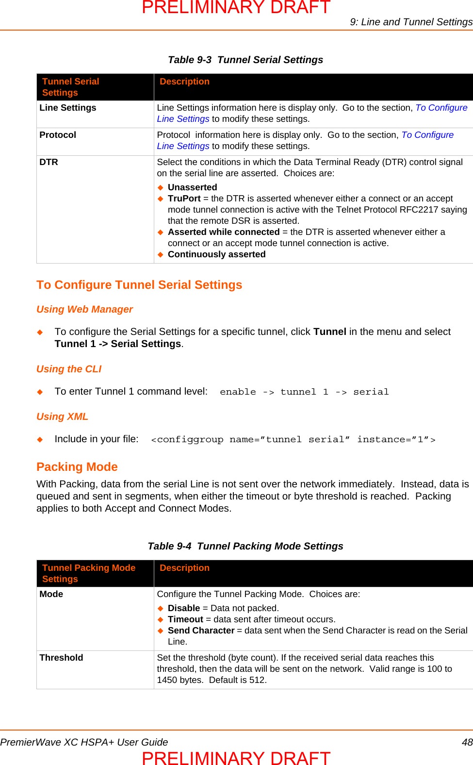
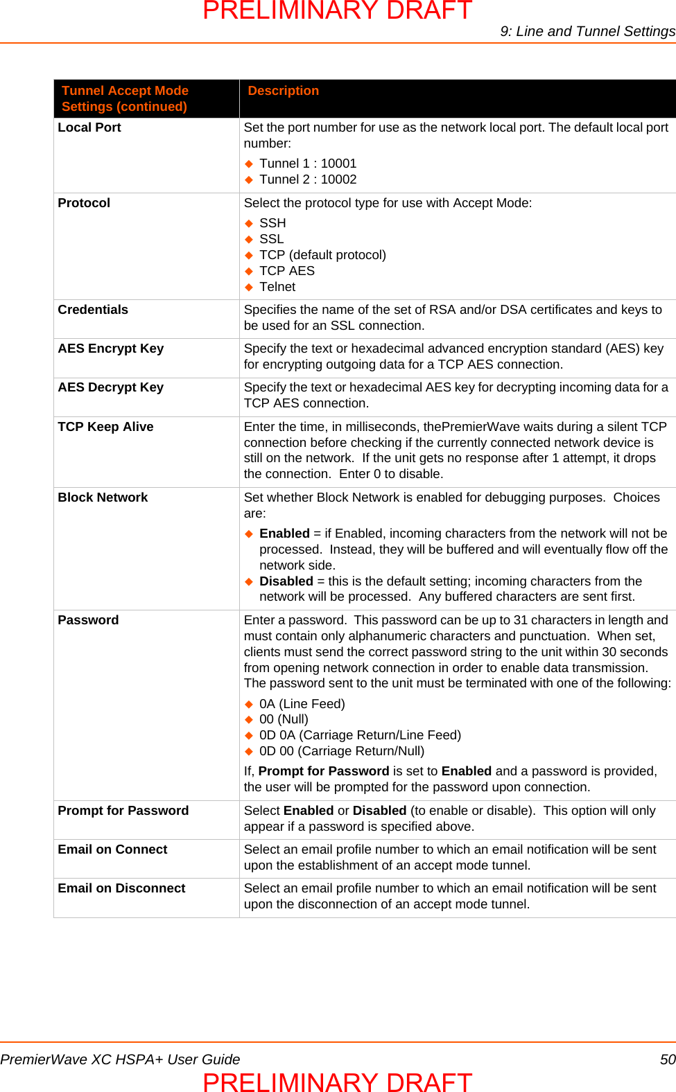
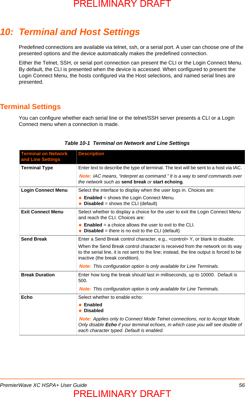
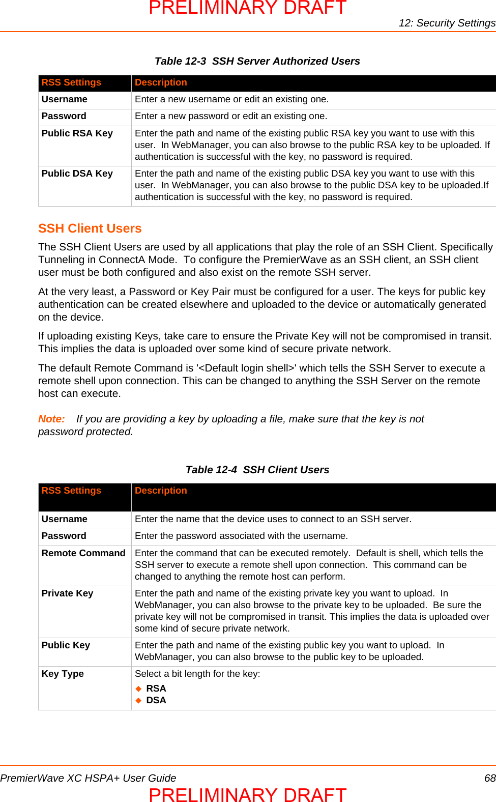
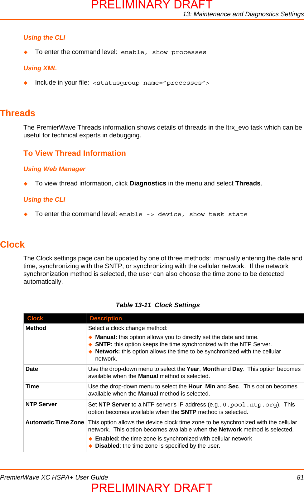
![9: Line and Tunnel SettingsPremierWave XC HSPA+ User Guide 46Table 9-2 Line Command Mode SettingsTo Configure Line SettingsNote: The following section describes the steps to view and configure Line 1 settings; these steps apply to other line instances of the device.Data Bits Set the number of data bits for the Line. The default is 8.Stop Bits Set the number of stop bits for the Line. The default is 1.Flow Control Set the flow control for the Line. The default is None.Xon Char Set Xon Char to be used when Flow Control is set to Software. Prefix decimal with \ or prefix hexadecimal with 0x or prefix a single control character <control>.Xoff Char Set Xoff Char to be used when Flow Control is set to Software. Prefix decimal with \ or prefix hexadecimal with 0x or prefix a single control character <control>.Gap Timer Set the Gap Timer delay to Set the number of milliseconds to pass from the last character received before the driver forwards the received serial bytes. By default, the delay is four character periods at the current baud rate (minimum 1 msec).Threshold Set the number of threshold bytes which need to be received in order for the driver to forward received characters.Line Command Mode Settings DescriptionMode Set the Command Mode state of the Line. When in Command Mode, a CLI session operates exclusively on the Line. Choices are:AlwaysUser Serial StringDisabledNote: In order to enable Command Mode on the Line, Tunneling on the Line must be Disabled (both Connect and Accept modes). Also, custom baud rates are not supported in Command Mode.Wait Time Enter the amount of time to wait during boot time for the Serial String. This timer starts right after the Signon Message has been set on the Serial Line and applies only if mode is “Use Serial String”.Serial String Enter the Text or Binary string of bytes that must be read on the Serial Line during boot time in order to enable Command Mode. It may contain a time element to specify a required delay in milliseconds x, formed as {x}. Applies only if mode is “User Serial String”. It may contain a binary character(s) of the form [x]. For example, use decimal [12] or hex [0xc].Echo Serial String Select Enable or Disable for Echo Serial String. Applies only if mode is “User Serial String”. Select enable to echo received characters backed out on the line while looking for the serial string.Signon Message Enter the string of bytes to be sent to the Serial Line during boot time. It may contain a binary character(s) of the form [x]. For example, use decimal [12] or hex [0xc].Line Settings (continued) DescriptionPRELIMINARY DRAFTPRELIMINARY DRAFT](https://usermanual.wiki/lantronix/PWXCHSPA/User-Guide-1954943-Page-46.png)
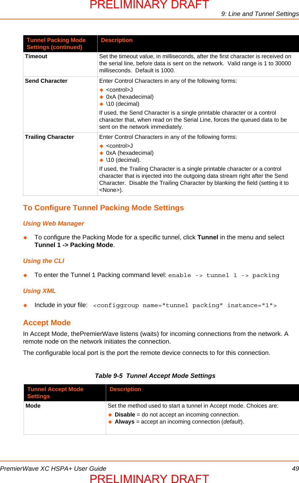
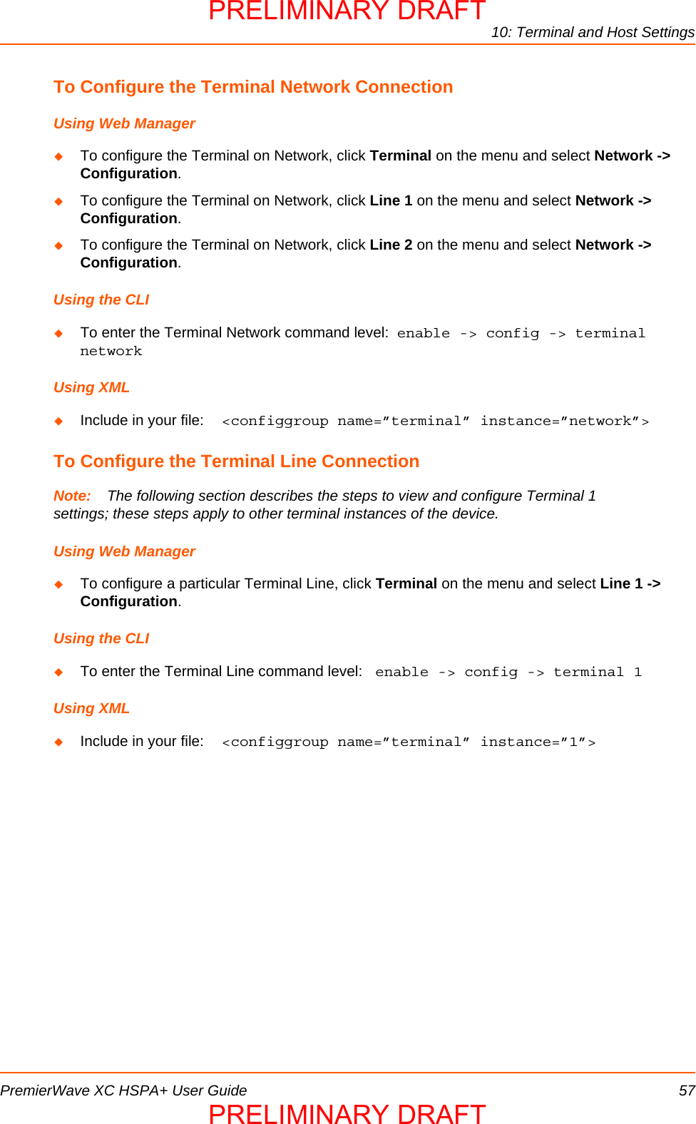
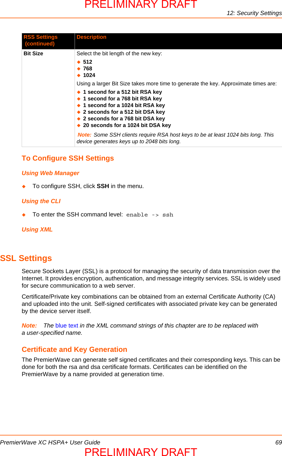

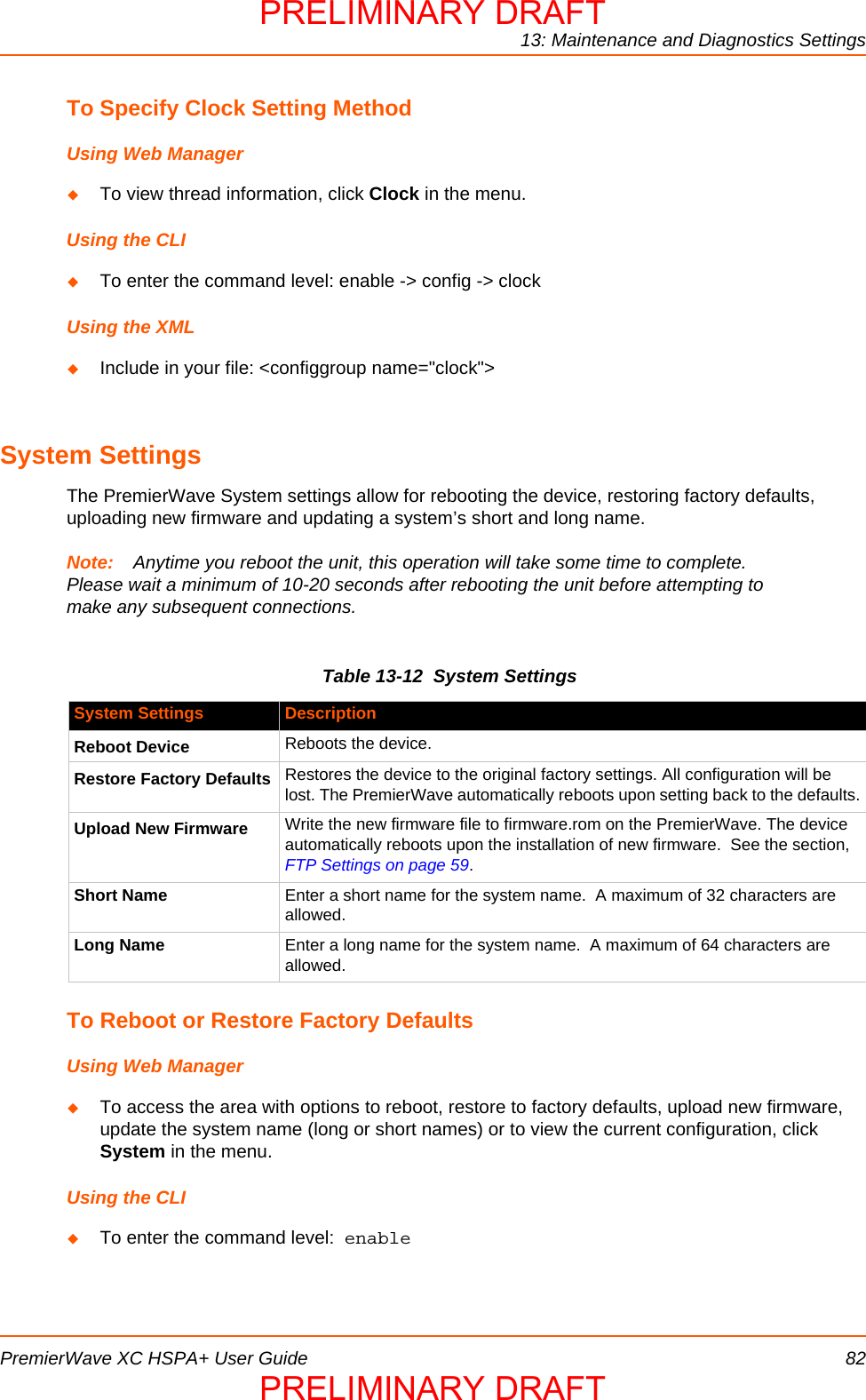
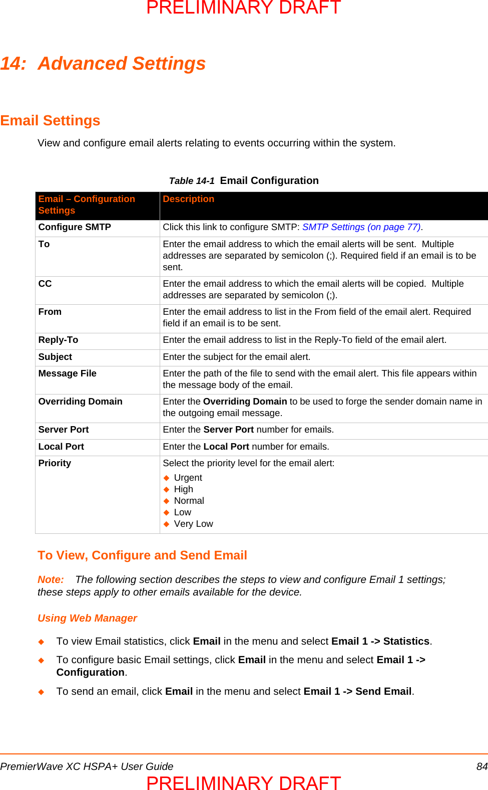
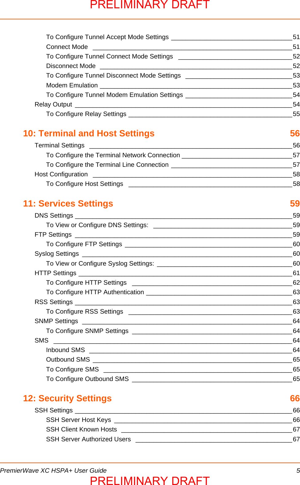
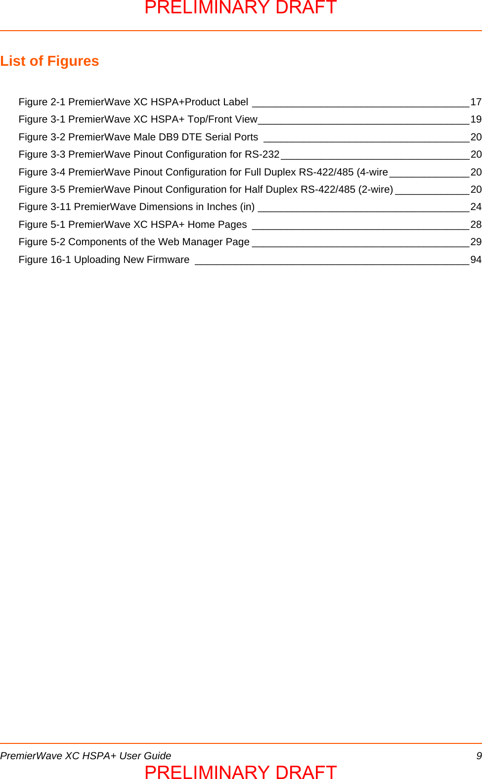
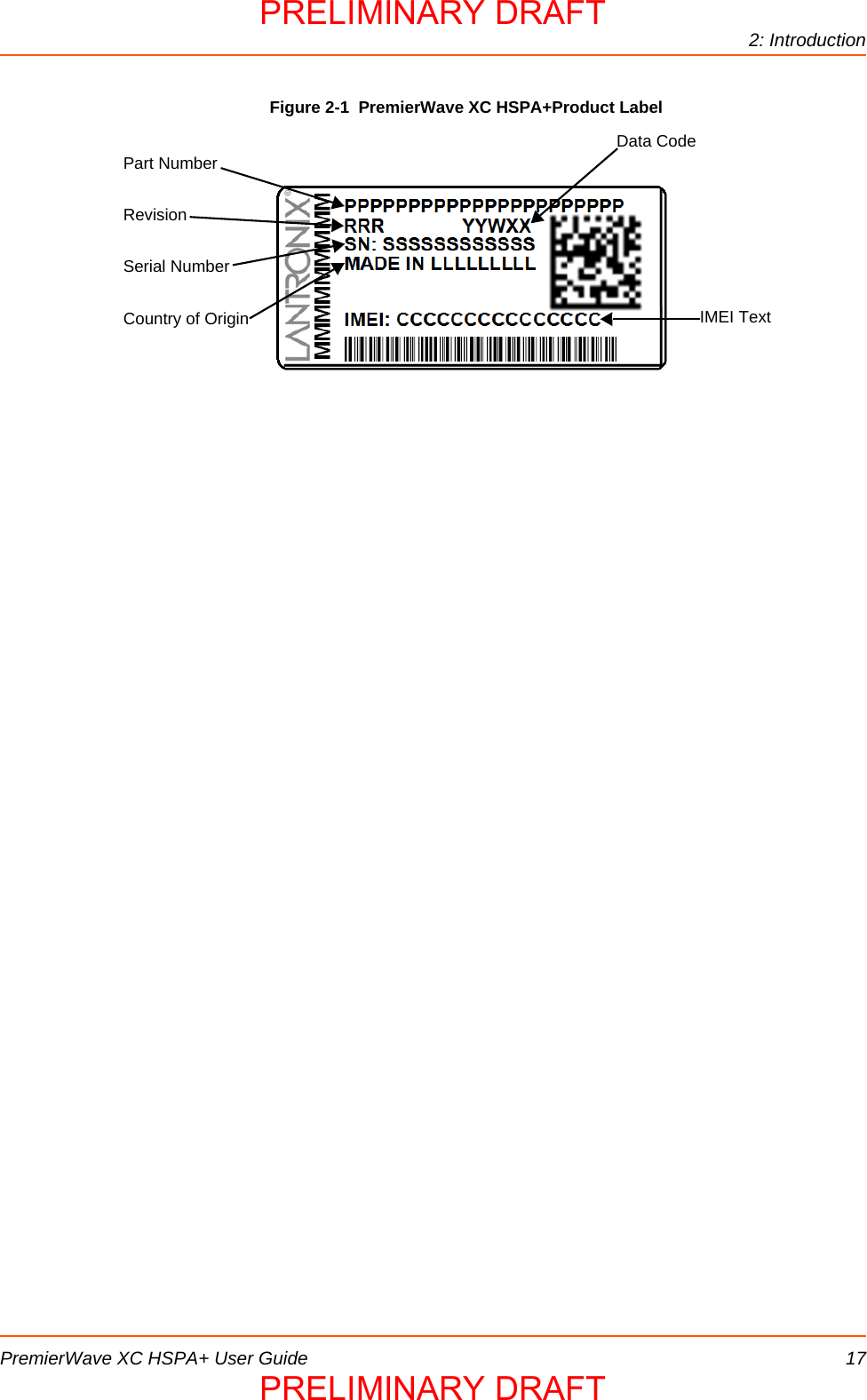
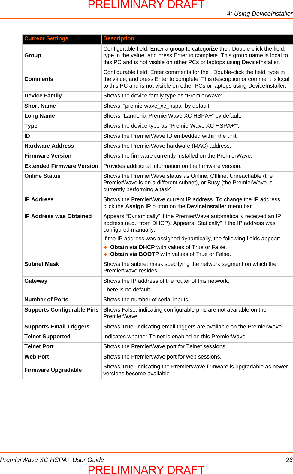
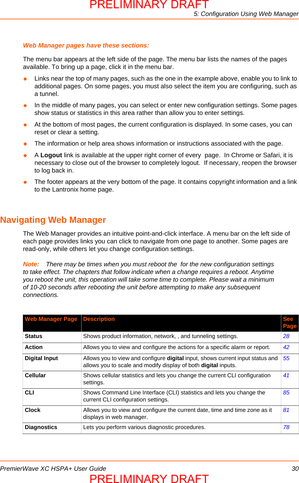
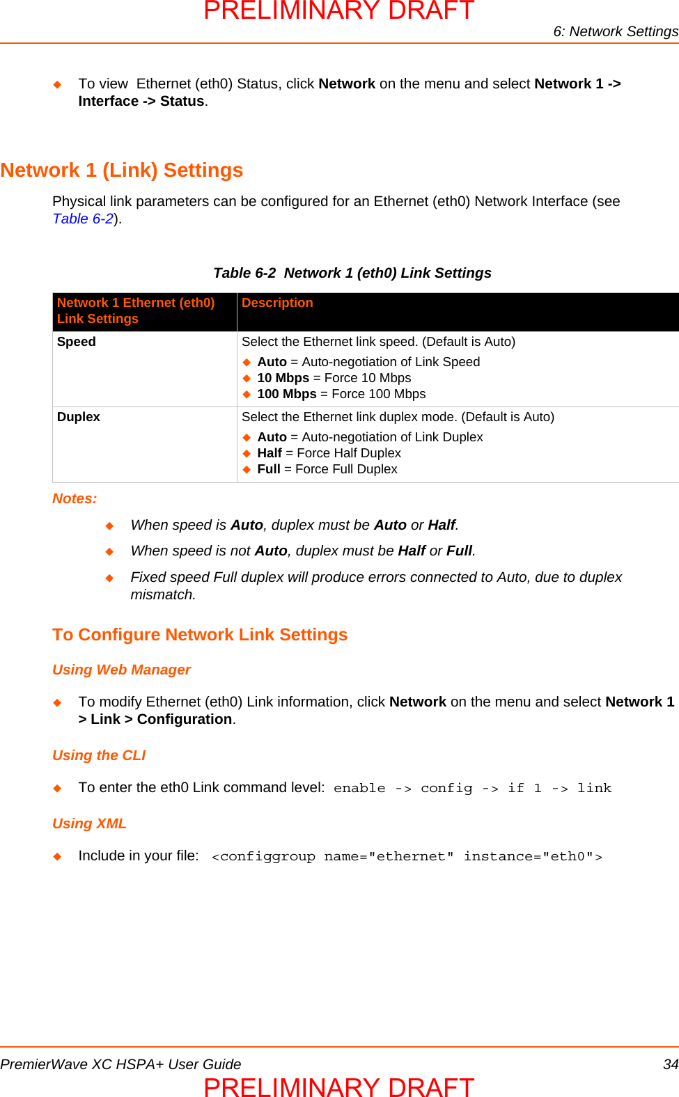
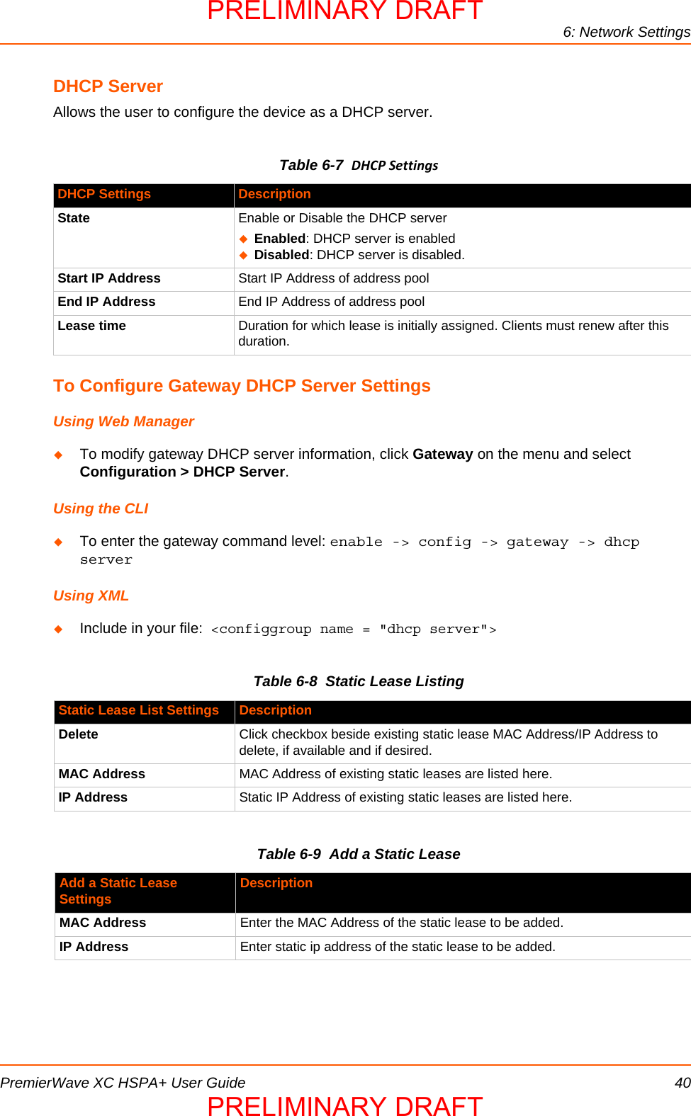
![14: Advanced SettingsPremierWave XC HSPA+ User Guide 85Using the CLITo enter Email command level: enable -> email 1Using XMLInclude in your file: <configgroup name=”email” instance=”1”>Command Line Interface SettingsThe Command Line Interface settings allow you to control how users connect to and interact with the PremierWave's command line. It is possible to configure access via the Telnet and SSH protocols, in addition to general CLI options.Basic CLI SettingsThe basic CLI settings control general CLI access and usability options.Table 14-2 CLI Configuration SettingsTo View and Configure Basic CLI SettingsUsing Web ManagerTo view CLI statistics, click CLI in the menu and select Statistics. To configure basic CLI settings, click CLI in the menu and select Configuration.Using the CLITo enter CLI command level: enable -> config -> cliUsing XMLInclude in your file: <configgroup name=”cli”>Command Line Interface Configuration Settings DescriptionLogin Password Enter the password for logins by the admin account. The default password is “PASS”.Enable Level Password Enter the password for access to the Command Mode Enable level. There is no password by default.Quit Connect Line Enter the Quit Connect Line string to be used to terminate a telnet or SSH session and resume the CLI. Type <control> before the key to be pressed while holding down the [Ctrl] key (example: <control>L)Inactivity Timeout Set a time period in which the CLI session should disconnect if no data is received. Enter 0 to disable. Blank the display field to restore the default.Line Authentication Enable or Disable authentication for CLI access on the .PRELIMINARY DRAFTPRELIMINARY DRAFT](https://usermanual.wiki/lantronix/PWXCHSPA/User-Guide-1954943-Page-85.png)


![PremierWave XC HSPA+ User Guide 108Appendix E: USB-CDC-ACM Device Driver Filefor Windows HostsThe following file may be used to enable Windows to recognize the USB-CDC-ACM connection to the PremierWave's USB Device port. Create the linux-cdc-acm.inf file on the Windows host somewhere using the contents provided below. When Windows prompts for a device driver for the USB connection, point it to this file.Note: For Windows 7 installation, it is recommended to manually install the driver before plugging in the USB cable to the PremierWave device port. This can be done by installing a legacy driver for a COM port, with the Have Disk... option.; Windows USB CDC ACM Setup File; Based on INF template which was:; Copyright (c) 2000 Microsoft Corporation; Copyright (c) 2007 Microchip Technology Inc.; likely to be covered by the MLPL as found at:; <http://msdn.microsoft.com/en-us/cc300389.aspx#MLPL>.; For use only on Windows operating systems.[Version]Signature="$Windows NT$"Class=PortsClassGuid={4D36E978-E325-11CE-BFC1-08002BE10318}Provider=%Linux%DriverVer=11/15/2007,5.1.2600.0[Manufacturer]%Linux%=DeviceList, NTamd64[DestinationDirs]DefaultDestDir=12;-----------------------------------------------------------------------; Windows 2000/XP/Vista-32bit Sections;-----------------------------------------------------------------------[DriverInstall.nt]include=mdmcpq.infCopyFiles=DriverCopyFiles.ntAddReg=DriverInstall.nt.AddReg[DriverCopyFiles.nt]usbser.sys,,,0x20[DriverInstall.nt.AddReg]HKR,,DevLoader,,*ntkernHKR,,NTMPDriver,,USBSER.sysHKR,,EnumPropPages32,,"MsPorts.dll,SerialPortPropPageProvider"[DriverInstall.nt.Services]AddService=usbser, 0x00000002, DriverService.nt[DriverService.nt]DisplayName=%SERVICE%ServiceType=1StartType=3ErrorControl=1ServiceBinary=%12%\USBSER.sysPRELIMINARY DRAFTPRELIMINARY DRAFT](https://usermanual.wiki/lantronix/PWXCHSPA/User-Guide-1954943-Page-108.png)
![Appendix E: USB-CDC-ACM Device Driver File for Windows HostsPremierWave XC HSPA+ User Guide 109;-----------------------------------------------------------------------; Vista-64bit Sections;-----------------------------------------------------------------------[DriverInstall.NTamd64]include=mdmcpq.infCopyFiles=DriverCopyFiles.NTamd64AddReg=DriverInstall.NTamd64.AddReg[DriverCopyFiles.NTamd64]USBSER.sys,,,0x20[DriverInstall.NTamd64.AddReg]HKR,,DevLoader,,*ntkernHKR,,NTMPDriver,,USBSER.sysHKR,,EnumPropPages32,,"MsPorts.dll,SerialPortPropPageProvider"[DriverInstall.NTamd64.Services]AddService=usbser, 0x00000002, DriverService.NTamd64[DriverService.NTamd64]DisplayName=%SERVICE%ServiceType=1StartType=3ErrorControl=1ServiceBinary=%12%\USBSER.sys;-----------------------------------------------------------------------; Vendor and Product ID Definitions;-----------------------------------------------------------------------; When developing your USB device, the VID and PID used in the PC side; application program and the firmware on the microcontroller must match.; Modify the below line to use your VID and PID. Use the format as shown; below.; Note: One INF file can be used for multiple devices with different; VID and PIDs. For each supported device, append; ",USB\VID_xxxx&PID_yyyy" to the end of the line.;-----------------------------------------------------------------------[SourceDisksFiles][SourceDisksNames][DeviceList]%DESCRIPTION%=DriverInstall, USB\VID_0525&PID_A4A7, USB\VID_0525&PID_A4AB&MI_02[DeviceList.NTamd64]%DESCRIPTION%=DriverInstall, USB\VID_0525&PID_A4A7, USB\VID_0525&PID_A4AB&MI_02;-----------------------------------------------------------------------; String Definitions;-----------------------------------------------------------------------;Modify these strings to customize your device;-----------------------------------------------------------------------[Strings]Linux = "Linux Developer Community"DESCRIPTION = "Gadget Serial"SERVICE = "USB RS-232 Emulation Driver"PRELIMINARY DRAFTPRELIMINARY DRAFT](https://usermanual.wiki/lantronix/PWXCHSPA/User-Guide-1954943-Page-109.png)