lantronix PWXCHSPA PremierWave XC HSPA+ User Manual PWXC HSPA BP UG2
lantronix PremierWave XC HSPA+ PWXC HSPA BP UG2
User Manual

Part Number 900-678-R
Revision A May 2013
PremierWave XC
HSPA+ User Guide
PRELIMINARY DRAFT
PRELIMINARY DRAFT

PremierWave XC HSPA+ User Guide 2
Copyright & Trademark
© 2013 Lantronix, Inc. All rights reserved. No part of the contents of this book may be transmitted
or reproduced in any form or by any means without the written permission of Lantronix.
Lantronix® registered trademark of Lantronix, Inc. DeviceInstaller and PremierWave© are
trademark of Lantronix, Inc.
Windows® and Internet Explorer® are registered trademarks of Microsoft Corporation. Mozilla®
and Firefox® are registered trademarks of the Mozilla Foundation. Chrome™ is a trademark of
Google, Inc. Opera™ is a trademark of Opera Software ASA. Tera Terma is a registered
trademark of Vector, Inc. All other trademarks and trade names are the property of their
respective holders.
Warranty
For details on the Lantronix warranty policy, please go to our web site at
www.lantronix.com/support/warranty.
Contacts
Lantronix Corporate Headquarters
167 Technology Drive
Irvine, CA 92618, USA
Toll Free: 800-526-8766
Phone: 949-453-3990
Fax: 949-450-7249
Technical Support
Online: www.lantronix.com/support
Sales Offices
For a current list of our domestic and international sales offices, go to the Lantronix web site at
www.lantronix.com/about/contact.
Disclaimer
The information in this guide may change without notice. The manufacturer assumes no
responsibility for any errors that may appear in this guide.
Revision History
Date Rev. Comments
May 2013 A Initial document for firmware release 7.7.0.0R27.
PRELIMINARY DRAFT
PRELIMINARY DRAFT

PremierWave XC HSPA+ User Guide 3
Table of Contents
List of Figures _____________________________________________________________9
List of Tables _____________________________________________________________10
1: Using This Guide 12
Purpose and Audience _____________________________________________________12
Summary of Chapters ______________________________________________________12
Additional Documentation ___________________________________________________13
2: Introduction 14
Key Features _____________________________________________________________14
Applications ______________________________________________________________14
Protocol Support _________________________________________________________14
Troubleshooting Capabilities _________________________________________________15
Configuration Methods _____________________________________________________15
Addresses and Port Numbers ________________________________________________16
Hardware Address _____________________________________________________16
IP Address ___________________________________________________________16
Port Numbers _________________________________________________________16
Product Information Label ___________________________________________________16
3: Installation of PremierWave XC HSPA+ 18
Package Contents _________________________________________________________18
User-Supplied Items _______________________________________________________18
Hardware Components ____________________________________________________18
Front/Top Panel _______________________________________________________18
Back Panel ___________________________________________________________23
Installing the PremierWave XC HSPA+ ________________________________________23
4: Using DeviceInstaller 25
Accessing PremierWave Using DeviceInstaller __________________________________25
Device Detail Summary _____________________________________________________25
5: Configuration Using Web Manager 27
Accessing Web Manager ___________________________________________________27
Device Status Page ____________________________________________________28
Web Manager Components _________________________________________________29
Navigating Web Manager ___________________________________________________30
PRELIMINARY DRAFT
PRELIMINARY DRAFT

PremierWave XC HSPA+ User Guide 4
6: Network Settings 32
Network 1 (eth0) Interface Settings ____________________________________________32
To Configure Network Interface Settings ____________________________________33
To View Network Interface Status _________________________________________33
Network 1 (Link) Settings ___________________________________________________34
To Configure Network Link Settings ________________________________________34
Network 1 (Failover) _______________________________________________________35
To Configure Network 1 Failover Settings ___________________________________35
Network 2 (Cellular) Settings ________________________________________________35
To Configure Network 2 (Cellular Interface) Settings ___________________________36
Network 2 (Link) Settings ___________________________________________________36
To Configure Link Settings _______________________________________________37
Gateway ________________________________________________________________37
WAN ________________________________________________________________37
To Configure Gateway WAN Settings ______________________________________38
Port Forwarding _______________________________________________________38
To Configure Gateway Port Forwarding Settings ______________________________38
Static Routes _________________________________________________________39
To Configure Gateway Static Route Settings _________________________________39
DHCP Server _________________________________________________________40
To Configure Gateway DHCP Server Settings ________________________________40
7: Cellular 41
To Configure Cellular Settings ____________________________________________41
8: Action Settings 42
Alarms and Reports _______________________________________________________42
Actions _________________________________________________________________42
To Configure Action Settings _____________________________________________43
Digital Input ______________________________________________________________44
To Configure Digital Input Settings _________________________________________44
9: Line and Tunnel Settings 45
Line Settings _____________________________________________________________45
To Configure Line Settings _______________________________________________46
To View Line Statistics __________________________________________________47
Tunnel Settings ___________________________________________________________47
Serial Settings ________________________________________________________47
To Configure Tunnel Serial Settings ________________________________________48
Packing Mode _________________________________________________________48
To Configure Tunnel Packing Mode Settings _________________________________49
Accept Mode __________________________________________________________49
PRELIMINARY DRAFT
PRELIMINARY DRAFT

PremierWave XC HSPA+ User Guide 5
To Configure Tunnel Accept Mode Settings __________________________________51
Connect Mode ________________________________________________________51
To Configure Tunnel Connect Mode Settings ________________________________52
Disconnect Mode ______________________________________________________52
To Configure Tunnel Disconnect Mode Settings ______________________________53
Modem Emulation ______________________________________________________53
To Configure Tunnel Modem Emulation Settings ______________________________54
Relay Output _____________________________________________________________54
To Configure Relay Settings ______________________________________________55
10: Terminal and Host Settings 56
Terminal Settings _________________________________________________________56
To Configure the Terminal Network Connection _______________________________57
To Configure the Terminal Line Connection __________________________________57
Host Configuration ________________________________________________________58
To Configure Host Settings ______________________________________________58
11: Services Settings 59
DNS Settings _____________________________________________________________59
To View or Configure DNS Settings: _______________________________________59
FTP Settings _____________________________________________________________59
To Configure FTP Settings _______________________________________________60
Syslog Settings ___________________________________________________________60
To View or Configure Syslog Settings: ______________________________________60
HTTP Settings ____________________________________________________________61
To Configure HTTP Settings _____________________________________________62
To Configure HTTP Authentication _________________________________________63
RSS Settings _____________________________________________________________63
To Configure RSS Settings ______________________________________________63
SNMP Settings ___________________________________________________________64
To Configure SNMP Settings _____________________________________________64
SMS ___________________________________________________________________64
Inbound SMS _________________________________________________________64
Outbound SMS ________________________________________________________65
To Configure SMS _____________________________________________________65
To Configure Outbound SMS _____________________________________________65
12: Security Settings 66
SSH Settings _____________________________________________________________66
SSH Server Host Keys __________________________________________________66
SSH Client Known Hosts ________________________________________________67
SSH Server Authorized Users ____________________________________________67
PRELIMINARY DRAFT
PRELIMINARY DRAFT

PremierWave XC HSPA+ User Guide 6
SSH Client Users ______________________________________________________68
To Configure SSH Settings ______________________________________________69
SSL Settings _____________________________________________________________69
Certificate and Key Generation ___________________________________________69
To Create a New Credential ______________________________________________70
Certificate Upload Settings _______________________________________________71
To Configure an Existing SSL Credential ____________________________________71
Trusted Authorities _____________________________________________________72
To Upload an Authority Certificate _________________________________________72
13: Maintenance and Diagnostics Settings 73
Filesystem Settings ________________________________________________________73
File Display ___________________________________________________________73
To Display Files _______________________________________________________73
File Modification _______________________________________________________74
File Transfer __________________________________________________________74
To Transfer or Modify Filesystem Files ______________________________________75
Protocol Stack Settings _____________________________________________________75
IP Settings ___________________________________________________________75
To Configure IP Network Stack Settings ____________________________________75
ICMP Settings _________________________________________________________76
To Configure ICMP Network Stack Settings __________________________________76
ARP Settings _________________________________________________________76
To Configure ARP Network Stack Settings __________________________________76
SMTP Settings ___________________________________________________________77
To Configure SMTP Network Stack Settings _________________________________77
To Configure ARP Network Stack Settings __________________________________77
Diagnostics ______________________________________________________________78
Hardware ____________________________________________________________78
To View Hardware Information ____________________________________________78
IP Sockets ___________________________________________________________78
To View the List of IP Sockets ____________________________________________78
Ping ________________________________________________________________78
To Ping a Remote Host _________________________________________________79
Traceroute ___________________________________________________________79
To Perform a Traceroute ________________________________________________79
Log _________________________________________________________________79
To Configure the Diagnostic Log Output ____________________________________80
Memory ______________________________________________________________80
To View Memory Usage _________________________________________________80
Processes ____________________________________________________________80
To View Process Information _____________________________________________80
Threads _________________________________________________________________81
PRELIMINARY DRAFT
PRELIMINARY DRAFT

PremierWave XC HSPA+ User Guide 7
To View Thread Information ______________________________________________81
Clock ___________________________________________________________________81
To Specify Clock Setting Method __________________________________________82
System Settings __________________________________________________________82
To Reboot or Restore Factory Defaults _____________________________________82
Discovery and Query Port ___________________________________________________83
To Configure Discovery _________________________________________________83
14: Advanced Settings 84
Email Settings ____________________________________________________________84
To View, Configure and Send Email ________________________________________84
Command Line Interface Settings _____________________________________________85
Basic CLI Settings _____________________________________________________85
To View and Configure Basic CLI Settings ___________________________________85
Telnet Settings ________________________________________________________86
To Configure Telnet Settings _____________________________________________86
SSH Settings _________________________________________________________86
To Configure SSH Settings ______________________________________________87
XML Settings _____________________________________________________________87
XML: Export Configuration _______________________________________________87
To Export Configuration in XML Format _____________________________________88
XML: Export Status _____________________________________________________88
To Export in XML Format ________________________________________________88
XML: Import Configuration _______________________________________________89
To Import Configuration in XML Format _____________________________________89
15: Security in Detail 91
Public Key Infrastructure ____________________________________________________91
TLS (SSL) _______________________________________________________________91
Digital Certificates _________________________________________________________91
Trusted Authorities ________________________________________________________91
Obtaining Certificates ______________________________________________________92
Self-Signed Certificates _____________________________________________________92
Certificate Formats ________________________________________________________92
OpenSSL ________________________________________________________________92
Steel Belted RADIUS ______________________________________________________93
Free RADIUS ____________________________________________________________93
16: Updating Firmware 94
Obtaining Firmware ________________________________________________________94
Loading New Firmware through Web Manager __________________________________94
Loading New Firmware through FTP __________________________________________95
PRELIMINARY DRAFT
PRELIMINARY DRAFT

PremierWave XC HSPA+ User Guide 8
17: Branding the PremierWave XC HSPA+ 96
Web Manager Customization ________________________________________________96
Short and Long Name Customization __________________________________________97
To Customize Short or Long Names _______________________________________97
Appendix A: Technical Specifications 98
Network _________________________________________________________________98
Cellular ______________________________________________________________98
Ethernet _____________________________________________________________98
Serial Interface ___________________________________________________________98
Serial Connector __________________________________________________________98
USB Interface ____________________________________________________________98
USB Connector ___________________________________________________________99
I/O Interface _____________________________________________________________99
Input ________________________________________________________________99
Output _______________________________________________________________99
I/O Connectors ___________________________________________________________99
LED Indicators ____________________________________________________________99
Security _________________________________________________________________99
Management ____________________________________________________________100
Software _______________________________________________________________100
Power _________________________________________________________________100
Environmental ___________________________________________________________100
Agency Approvals / Compliance _____________________________________________100
Dimensions _____________________________________________________________101
Warranty _______________________________________________________________101
Appendix B: Compliance 102
Appendix C: Technical Support 105
Appendix D: Binary to Hexadecimal Conversions 106
Converting Binary to Hexadecimal ___________________________________________106
Conversion Table _____________________________________________________106
Scientific Calculator ___________________________________________________106
Appendix E: USB-CDC-ACM Device Driver File
for Windows Hosts 108
PRELIMINARY DRAFT
PRELIMINARY DRAFT

PremierWave XC HSPA+ User Guide 9
List of Figures
Figure 2-1 PremierWave XC HSPA+Product Label ______________________________________17
Figure 3-1 PremierWave XC HSPA+ Top/Front View_____________________________________19
Figure 3-2 PremierWave Male DB9 DTE Serial Ports ____________________________________20
Figure 3-3 PremierWave Pinout Configuration for RS-232_________________________________20
Figure 3-4 PremierWave Pinout Configuration for Full Duplex RS-422/485 (4-wire______________20
Figure 3-5 PremierWave Pinout Configuration for Half Duplex RS-422/485 (2-wire) _____________20
Figure 3-11 PremierWave Dimensions in Inches (in) _____________________________________24
Figure 5-1 PremierWave XC HSPA+ Home Pages ______________________________________28
Figure 5-2 Components of the Web Manager Page ______________________________________29
Figure 16-1 Uploading New Firmware ________________________________________________94
PRELIMINARY DRAFT
PRELIMINARY DRAFT

PremierWave XC HSPA+ User Guide 10
List of Tables
Table 3-6 PremierWave LEDs and Descriptions ________________________________________21
Table 3-7 Cellular Signal Strength Indicator ___________________________________________21
Table 3-8 Diagnostic LED Indications ________________________________________________22
Table 3-9 PremierWave Bottom/Back Panel View _______________________________________23
Table 3-10 PremierWave XC HSPA+ Connections (Side) _________________________________23
Table 6-1 Network Interface Settings _________________________________________________32
Table 6-2 Network 1 (eth0) Link Settings ______________________________________________34
Table 6-3 WAN Configuration ______________________________________________________37
Table 6-4 Port Forwarding Rules List _________________________________________________38
Table 6-5 Adding a New Port Forwarding Rule _________________________________________38
Table 6-6 Adding a New Static Route ________________________________________________39
Table 6-7 DHCP Settings __________________________________________________________40
Table 6-8 Static Lease Listing ______________________________________________________40
Table 6-9 Add a Static Lease _______________________________________________________40
Table 8-1 Action Settings __________________________________________________________42
Table 8-2 Digital Input Settings _____________________________________________________44
Table 9-1 Line Configuration Settings ________________________________________________45
Table 9-2 Line Command Mode Settings ______________________________________________46
Table 9-3 Tunnel Serial Settings ____________________________________________________48
Table 9-4 Tunnel Packing Mode Settings _____________________________________________48
Table 9-5 Tunnel Accept Mode Settings ______________________________________________49
Table 9-6 Tunnel Connect Mode Settings _____________________________________________51
Table 9-7 Tunnel Disconnect Mode Settings ___________________________________________53
Table 9-8 Tunnel Modem Emulation Settings __________________________________________53
Table 9-9 Relay Output Settings ____________________________________________________55
Table 10-1 Terminal on Network and Line Settings ______________________________________56
Table 10-2 Host Configuration ______________________________________________________58
Table 11-1 DNS Settings __________________________________________________________59
Table 11-2 FTP Settings __________________________________________________________59
Table 11-3 Syslog Settings ________________________________________________________60
Table 11-4 HTTP Settings _________________________________________________________61
Table 11-5 HTTP Authentication Settings _____________________________________________62
Table 11-6 RSS Settings __________________________________________________________63
Table 11-7 SNMP Settings _________________________________________________________64
Table 11-8 Inbound SMS Settings ___________________________________________________64
Table 11-9 Outbound SMS Settings _________________________________________________65
PRELIMINARY DRAFT
PRELIMINARY DRAFT

PremierWave XC HSPA+ User Guide 11
Table 12-1 SSH Server Host Keys ___________________________________________________66
Table 12-2 SSH Client Known Hosts _________________________________________________67
Table 12-3 SSH Server Authorized Users _____________________________________________68
Table 12-4 SSH Client Users _______________________________________________________68
Table 12-5 Certificate and Key Generation Settings _____________________________________70
Table 12-6 Upload Certificate Settings _______________________________________________71
Table 12-7 Trusted Authority Settings ________________________________________________72
Table 13-1 File Display Settings ____________________________________________________73
Table 13-2 File Modification Settings _________________________________________________74
Table 13-3 File Transfer Settings ____________________________________________________74
Table 13-4 IP Network Stack Settings ________________________________________________75
Table 13-5 ICMP Network Stack Settings _____________________________________________76
Table 13-6 ARP Network Stack Settings ______________________________________________76
Table 13-7 SMTP Network Stack Settings _____________________________________________77
Table 13-8 Ping Settings __________________________________________________________78
Table 13-9 Traceroute Settings _____________________________________________________79
Table 13-10 Log Settings __________________________________________________________79
Table 13-11 Clock Settings ________________________________________________________81
Table 13-12 System Settings _______________________________________________________82
Table 13-13 Discovery Settings _____________________________________________________83
Table 14-1 Email Configuration _____________________________________________________84
Table 14-2 CLI Configuration Settings ________________________________________________85
Table 14-3 Telnet Settings ________________________________________________________86
Table 14-4 SSH Settings __________________________________________________________86
Table 14-5 XML Exporting Configuration ______________________________________________87
Table 14-6 Exporting Status ________________________________________________________88
Table 14-7 Import Configuration from Filesystem Settings ________________________________89
Table 17-1 Short and Long Name Settings ____________________________________________97
PRELIMINARY DRAFT
PRELIMINARY DRAFT

PremierWave XC HSPA+ User Guide 12
1: Using This Guide
Purpose and Audience
This guide provides the information needed to configure, use, and update the PremierWave XC
HSPA+. It is intended for software developers and system integrators who are installing this
product into their designs.
Summary of Chapters
The remaining chapters in this guide include:
Chapter Description
2: Introduction Main features of the product and the protocols it supports.
Includes technical specifications.
3: Installation of PremierWave XC
HSPA+ Instructions for installing the PremierWave XC HSPA+.
4: Using DeviceInstaller Instructions for viewing the current configuration using
DeviceInstaller.
5: Configuration Using Web Manager Instructions for accessing Web Manager and using it to configure
settings for the device.
6: Network Settings Instructions for configuring network settings.
7: Cellular Instructions for configuring cellular settings.
8: Action Settings Instructions for configuring alarm settings.
9: Line and Tunnel Settings Instructions for configuring and tunnel settings.
10: Terminal and Host Settings Instructions for configuring terminal and host settings.
11: Services Settings Instructions for configuring DNS, FTP, HTTP and Syslog settings.
12: Security Settings Instructions for configuring SSL security settings.
13: Maintenance and Diagnostics
Settings Instructions to maintain the , view statistics, files, and diagnose
problems.
14: Advanced Settings Instructions for configuring email, CLI and XML settings.
15: Security in Detail Provides additional information on security settings available.
16: Updating Firmware Instructions for obtaining the latest firmware and updating the .
17: Branding the PremierWave XC
HSPA+ Instructions on how to brand your device.
Appendix A: Technical Specifications Technical specifications for the device.
Appendix C: Technical Support Instructions for contacting Lantronix Technical Support.
Appendix D: Binary to Hexadecimal
Conversions Instructions for converting binary values to hexadecimals.
Appendix B: Compliance Lantronix compliance information.
Appendix E: USB-CDC-ACM Device
Driver File for Windows Hosts Information about the device driver file for windows host.
PRELIMINARY DRAFT
PRELIMINARY DRAFT

1: Using This Guide
PremierWave XC HSPA+ User Guide 13
Caution: To avoid electric shock and for the device to work properly, do not allow
cleaning solution to get inside the device, specifically the interface port
connectors, power connector, or power cord. Do not immerse the
device in any liquid.
Additional Documentation
Visit the Lantronix Web site at www.lantronix.com/support/documentation for the latest
documentation and the following additional documentation.
Document Description
PremierWave XC HSPA+
Command Reference Instructions for accessing Command Mode (the command line
interface) using a Telnet connection, SSH connection or through the
port. Detailed information about the commands. Also provides details
for XML configuration and status.
PremierWave XC HSPA+ Quick
Start Guide Instructions for getting the PremierWave up and running.
DeviceInstaller Online Help Instructions for using the Lantronix Windows-based utility to locate the
PremierWave and to view its current settings.
PRELIMINARY DRAFT
PRELIMINARY DRAFT

PremierWave XC HSPA+ User Guide 14
2: Introduction
PremierWave XC HSPA+ is a multi-port device server offering ethernet and cellular connectivity
for remote access and easy management of machines or equipment over the network and across
the internet.
Key Features
Power Supply: 9-30VDC input voltage through locking barrel connector. 12V wall cube
power supply included with unit.
Controller: 32-bit ARM9 microprocessor running at 400 megahertz (Mhz) with 16 Kilobytes
(KB) Data Cache and 16 KB of Instruction Cache.
Memory: 128 MB SDRAM, 64 MB NAND Flash, and 8 MB serial SPI Flash.
Serial Ports: Two 300 to 921 kbaud, RS-232/422/485 serial ports providing serial to Ethernet
and serial to cellular tunneling
Ethernet to cellular routing
UMTS HSPA+
Digital Inputs: two configurable inputs suitable for TTL input levels, and tolerant of up to
30VDC input voltages that can trigger alerts.
Relay Outputs: 1 independently isolated mechanical form-C relay
Ethernet: 1 Port Ethernet 10Base-T or 100Base-TX (auto-sensing for speed, duplex and
cross-over CAT5 cable)
USB Ports: One 2.0 high speed USB port for device management and configuration
Temperature Range: Operating temperature at -40° to +70°C. Storage temperature at -40° to
+85°C.
Applications
The PremierWave XC HSPA+ device server connects serial devices such as those listed below to
Ethernet and Cellular networks using the IP protocol family.
Patient Monitoring Devices
Glucose Analyzers
Infusion Pumps
Protocol Support
The PremierWave XC HSPA+ device server contains a full-featured IP stack. Supported protocols
include:
HSPA+, UMTS, EDGE, GSM, GPRS
PRELIMINARY DRAFT
PRELIMINARY DRAFT

2: Introduction
PremierWave XC HSPA+ User Guide 15
ARP, HTTP, HTTPS, SMTP AUTH, SNMP v1/v2c/v3, Modbus TCP, UDP/IP, TCP/IP, SSH,
SSL, TLS, RSS, UPnP, ICMP, BOOTP, DHCP, Auto IP, Telnet, SNTP, FTP, FTPS, DNS,
TFTP, XML and Syslog for network communications and management.
TFTP for uploading/downloading files.
FTP and HTTP/HTTPS web server for firmware upgrades and uploading/downloading files.
TCP/IP, UDP/IP, Telnet, SSH, SSL, TCP AES and UDP AES for command/response based
data acquisition application or alarm triggered connection
HTTP/HTTPS web based monitoring of input readings, chart and data logging
SMTP AUTH, HTTP/HTTPS Post, FTP/FTPS Put and SNMP Traps for alarm triggered
notification
SNTP for device clock synchronization
SMS for alarm triggered notification.
Troubleshooting Capabilities
The PremierWave XC HSPA+ offers a comprehensive diagnostic toolset that lets you troubleshoot
problems quickly and easily. Available from the CLI or Web Manager, the diagnostic tools let you:
View memory and IP socket information.
Perform ping and traceroute operations.
Conduct forward or reverse DNS lookup operations.
View all processes currently running on the PremierWave, including CPU utilization.
View system log messages.
Configuration Methods
After installation, the PremierWave requires configuration. For the unit to operate correctly on a
network, it must have a unique IP address on the network. There are four basic methods for
logging into the PremierWave and assigning IP addresses and other configurable settings:
Web Manager: View and configure all settings easily through a web browser using the
Lantronix Web Manager. (See “Configuration Using Web Manager” on page 27.)
DeviceInstaller: Configure the IP address and related settings and view current settings on
the PremierWave using a Graphical User Interface (GUI) on a PC attached to a network. You
will need the latest version of DeviceInstaller. (See “Using DeviceInstaller” on page 25.)
Command Mode: There are two methods for accessing Command Mode (CLI): making a
Telnet or SSH connection, or connecting a PC or other host running a terminal emulation
program to the unit’s USB port. (See the PremierWave XC HSPA+ Command Reference
Guide for instructions and available commands.)
XML: The PremierWave supports XML-based configuration and setup records that make
device configuration transparent to users and administrators. XML is easily editable with a
standard text or XML editor. (See the PremierWave XC HSPA+ Command Reference Guide
for instructions and commands.)
PRELIMINARY DRAFT
PRELIMINARY DRAFT

2: Introduction
PremierWave XC HSPA+ User Guide 16
Addresses and Port Numbers
Hardware Address
The hardware address is also referred to as the Ethernet address, physical address, or MAC
address. Sample hardware address:
00-80-A3-14-1B-18
00:80:A3:14:1B:18
IP Address
Every device connected to an IP network must have a unique IP address. This address references
the specific unit.
Port Numbers
Every TCP connection and every UDP datagram is defined by a destination and source IP
address, and a destination and source port number. For example, a Telnet server commonly uses
TCP port number 23.
The following is a list of the default server port numbers running on the :
TCP Port 22: SSH Server (Command Mode configuration)
TCP Port 23: Telnet Server (Command Mode configuration)
TCP Port 80: HTTP (Web Manager configuration)
TCP Port 21: FTP
UDP Port 30718: LDP (Lantronix Discovery Protocol) port
TCP/UDP Port 10001: Tunnel 1 (see note below)
UDP Port 1900 and TCP Port 30179: UPnP
Note: Additional TCP/UDP ports and tunnels will be available, depending on the product
type. The default numbering of each additional TCP/UDP port and corresponding tunnel
will increase sequentially (i.e., TCP/UDP Port 1000X: Tunnel X).
Product Information Label
The product information label on the unit contains the
following information about the specific unit:
Bar code
Product Revision
Part Number
Serial Number (MAC Address)
Manufacturing Date Code
Note: The hardware address on the
label is also the product serial number.
The hardware address on the label is the
address for the Ethernet (eth0) interface.
PRELIMINARY DRAFT
PRELIMINARY DRAFT

2: Introduction
PremierWave XC HSPA+ User Guide 17
Figure 2-1 PremierWave XC HSPA+Product Label
Part Number
Revision
Serial Number
Country of Origin
Data Code
IMEI Text
PRELIMINARY DRAFT
PRELIMINARY DRAFT

PremierWave XC HSPA+ User Guide 18
3: Installation of PremierWave XC HSPA+
This chapter describes how to install the PremierWave XC HSPA+ device server. It contains the
following sections:
Package Contents
User-Supplied Items
Hardware Components
Installing the PremierWave XC HSPA+
Package Contents
The PremierWave XC HSPA+ package includes the following items:
One PremierWave XC HSPA+ device
One Power Supply 12 VDC with international adapters
Two External Antenna, SMA Connector
One RJ-45 Ethernet Straight Cat5 Cable, 1.5 meter
Quick Start Guide
User-Supplied Items
To complete your installation, you need the following items:
RS-232/422/485 serial devices and sensors that require network connectivity.
A serial cable, as listed below, for each serial device. One end of the cable must have a
female DB9 connector for the serial port.
-
A null modem cable to connect the serial port to another DTE device.
-
A straight-through modem cable to connect the serial port to a DCE device.
An available connection to your Ethernet network and an Ethernet cable.
A working AC power outlet if the unit will be powered from an AC power adapter.
SIM card
Hardware Components
Front/Top Panel
Figure 3-1 shows the top panel view of the PremierWave. Table 3-6, Table 3-7 and Table 3-8 list
and explain the behavior of the LEDs on the top panel.
LED Indicators: 2 ethernet LEDs, 1 diagnostic LED, one USB LED, one cellular status LED,
two serial activity LEDs, 5 signal strength LEDS, two of which are dual-colored.
PRELIMINARY DRAFT
PRELIMINARY DRAFT

3: Installation of PremierWave XC HSPA+
PremierWave XC HSPA+ User Guide 19
Figure 3-1 PremierWave XC HSPA+ Top/Front View
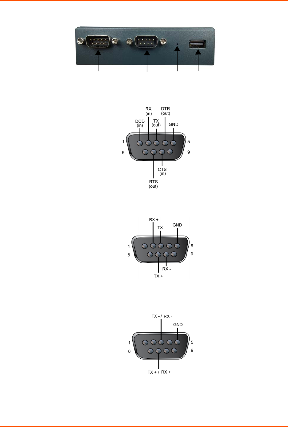
The PremierWave has two male DB9 serial ports that support RS-232/422/485. Figure 3-2 shows
the front view of the device. The default serial port settings are 9600 baud, 8 bits, no parity, 1 stop
bit, no flow control.
Signal
Strength
LEDs
Diagnostic
LED
PRELIMINARY DRAFT
PRELIMINARY DRAFT
3: Installation of PremierWave XC HSPA+
PremierWave XC HSPA+ User Guide 20
Figure 3-2 PremierWave Male DB9 DTE Serial Ports
Figure 3-3 PremierWave Pinout Configuration for RS-232
Figure 3-4 PremierWave Pinout Configuration for Full Duplex RS-422/485 (4-wire
Figure 3-5 PremierWave Pinout Configuration for Half Duplex RS-422/485 (2-wire)
Serial Serial Reset USB
1 2 Button Port
PRELIMINARY DRAFT
PRELIMINARY DRAFT

3: Installation of PremierWave XC HSPA+
PremierWave XC HSPA+ User Guide 21
Ethernet LEDs
The Ethernet Port has two LEDs that indicate the status of the connection as follows:
Left LED
Green ON 100Mbps Link
Green Blink 100Mbps Activity
Amber ON 10Mbps Link
Amber Blink 10Mbps Activity
Right LED
Green ON Full Duplex
OFF Half Duplex
The Ethernet port can connect to an Ethernet (10 Mbps) or Fast Ethernet (100 Mbps) network.
Table 3-6 PremierWave LEDs and Descriptions
Table 3-7 Cellular Signal Strength Indicator
LED Description
Power GREEN - displays a solid light when power is properly supplied.
OFF - no power supplied.
Cell Status GREEN - displays solid when there is a connection to the packet domain on the
cellular netowrk (e.g., a data or GPRS/UMTS/HSPA connection).
AMBER - displays solid when there is a connection to the cellular network (e.g.,
a GSM connection).
OFF - indicates WLAN interface is inactive or disabled.
Serial 1 GREEN - flashes when Serial port 2 is transmitting data.
AMBER - flashes when Serial port 2 is receiving data.
OFF - when no data is being transmitted or received through Serial port 2.
Serial 2 GREEN - flashes when Serial port 2 is transmitting data.
AMBER - flashes when Serial port 2 is receiving data.
OFF - when no data is being transmitted or received through Serial port 2.
USB GREEN - displays a solid light when a USB device is connected to USB 1 Host
port and is functioning properly.
OFF- when no USB device is connected to USB 1 Host port.
Signal Strength LEDs Indicates cellular signal strength when connection is established.
Signal Strength Color & Number of LED Signal Bars
Greater than or equal to -64 dBm 5 Green
Greater than or equal to -85 dBm and less than -64 dBm 4 Green
Greater than or equal to -75 dBm and less than -85 dBm 3 Green
Greater than or equal to -86 dBm and less than -75 dBm 2 Amber
Greater than or equal to -112 dBm and less than -86 dBm 1 Amber
Less than -113 dBm or unmeasurable All Off
PRELIMINARY DRAFT
PRELIMINARY DRAFT

3: Installation of PremierWave XC HSPA+
PremierWave XC HSPA+ User Guide 22
Table 3-8 Diagnostic LED Indications
Notes:
For Table 3-8 above, a “long” blink is 0.7 seconds of light followed by 0.3 seconds of
no light. A “short” blink is a light that is on for only 0.2 seconds and followed by 0.2
seconds of no light.
The diagnostic blink patterns reflect the highest priority fault condition. Also, the
Diagnostic LED will give an initial, identifying blink pattern to indicate the type of
diagnostic information it will display. All power and other non-network related
diagnostic patterns begin with one long blink. All wired LAN related diagnostics
patterns begin with two long blinks. All cellular-related diagnostics patterns begin with
three long blinks.
Reset Button
You can reset the PremierWave to factory defaults, including clearing the network settings. The IP
address, gateway, and netmask are set to 00s. To reset the unit to factory defaults, perform the
following steps.
1. Place the end of a paper clip or similar object into the reset opening (see Table 3-9) and press
and hold down micro switch during a power cycle for 10-15 seconds.
2. Remove the paper clip to release the button. The unit will continue the boot process restoring
it back to the original factory default settings.
Fault Conditions Blink Pattern
No Ethernet link when eth0 is enabled Long, long, short, short, 2 seconds off, continuous
No cellular link (no BSSID detected) when wlan0 is
enabled
Long, long, long, short, short, 2 seconds off,
continuous
No IP obtained from cellular when wlan0 is enabled
and the bridge mode is disabled.
Long, long, long, short, short, short, 2 seconds off,
continuous
Over temperature or when the internal temperature
reaches 85°F.
Long, short, short, short, 2 seconds off, continuous
Loss of power or when both the terminal and barrel
power input is below 9 volts.
Long, short, short, 2 seconds off, continuous
PRELIMINARY DRAFT
PRELIMINARY DRAFT

3: Installation of PremierWave XC HSPA+
PremierWave XC HSPA+ User Guide 23
Back Panel
On the PremierWave is a Power 1 Plug and RJ-45 Ethernet port as shown in Table 3-9.
Table 3-9 PremierWave Bottom/Back Panel View
Table 3-10 PremierWave XC HSPA+ Connections (Side)
Installing the PremierWave XC HSPA+
The device comes with brackets for mounting it, for example, on a wall. If using AC power, do not
use outlets controlled by a wall switch.
Observe the following guidelines when connecting the devices:
The PremierWave serial ports support RS-232/422/485.
Use a null modem cable to connect the serial port to another DTE device. Use a straight-
though (modem) cable to connect the serial port to a DCE device.
Connect your RJ-45 Ethernet cable to the RJ-45 port of the unit.
The PremierWave supports a power range of 9 to 30 VDC.
Note: As soon as you plug the device into power, the device powers up automatically,
the self-test begins, and LEDs would indicate the device's status
Connector Description
Relay Output Outputs Support 1A 24V
Inputs Inputs accept voltage 0 to 30 VDC.
ON Max 30 VDC
Min 2 VDC
OFF Max 0.7 VDC
Min 0 VDC
Antenna Ethernet Terminal Block Barrel Antenna
(RX Diversity) Power (6-pin) Plug
Power
Relay IN2 IN1
Relay CM2 CM1
PRELIMINARY DRAFT
PRELIMINARY DRAFT

3: Installation of PremierWave XC HSPA+
PremierWave XC HSPA+ User Guide 24
Perform the following steps to install your device:
1. With the power unplugged, insert your SIM card.
2. Connect an RJ-45 Ethernet cable between the unit and your Ethernet network.
3. Connect the antennas to the SMA connectors on the back. Do note that the safe distance due
to RF exposure from antenna is 20 cm.
Note: Antennas must be installed prior to powering on the unit. Do not remove or
connect the antennas while the unit power is on.
4. Plug the PremierWave into the power outlet by using the included power supply.
Figure 3-11 PremierWave Dimensions in Inches (in)
PRELIMINARY DRAFT
PRELIMINARY DRAFT

PremierWave XC HSPA+ User Guide 25
4: Using DeviceInstaller
This chapter covers the steps for locating a PremierWave XC HSPA+ unit and viewing its
properties and device details. DeviceInstaller is a free utility program provided by Lantronix that
discovers, configures, upgrades and manages Lantronix Device Servers.
Notes:
For instructions on using DeviceInstaller to configure the IP address and related
settings or for more advanced features, see the DeviceInstaller Online Help.
Auto IP generates a random IP address in the range of 169.254.0.1 to
169.254.255.254, with a netmask of 255.255.0.0, if no BOOTP or DHCP server is
found. These addresses are not routable.
Accessing PremierWave Using DeviceInstaller
Note: Make note of the MAC address. It may be needed to perform various functions in
DeviceInstaller.
To use the DeviceInstaller utility, first install the latest version from the downloads page on the
Lantronix web site www.lantronix.com/downloads.
1. Run the executable to start the installation process and respond to the installation wizard
prompts. (If prompted to select an installation type, select Typical.)
2. Click Start -> All Programs -> Lantronix -> DeviceInstaller 4.3 -> DeviceInstaller.
3. When DeviceInstaller starts, it will perform a network device search. To perform another
search, click Search.
4. Expand the PremierWave folder by clicking the + symbol next to the folder icon. The list of
available Lantronix PremierWave devices appears.
5. Select the PremierWave unit by expanding its entry and clicking on its IP address to view its
configuration.
6. On the right page, click the Device Details tab. The current configuration appears. This is
only a subset of the full configuration; the full configuration may be accessed via Web
Manager, CLI or XML.
Device Detail Summary
Note: The settings are Display Only in this table unless otherwise noted
Current Settings Description
Name Shows PremierWave XC HSPA+”.
DHCP Device Name One of the names the PremierWave will send to the DHCP server if it is
configured to obtain an address in this manner.
PRELIMINARY DRAFT
PRELIMINARY DRAFT

4: Using DeviceInstaller
PremierWave XC HSPA+ User Guide 26
Group Configurable field. Enter a group to categorize the . Double-click the field,
type in the value, and press Enter to complete. This group name is local to
this PC and is not visible on other PCs or laptops using DeviceInstaller.
Comments Configurable field. Enter comments for the . Double-click the field, type in
the value, and press Enter to complete. This description or comment is local
to this PC and is not visible on other PCs or laptops using DeviceInstaller.
Device Family Shows the device family type as “PremierWave”.
Short Name Shows “premierwave_xc_hspa” by default.
Long Name Shows “Lantronix PremierWave XC HSPA+” by default.
Type Shows the device type as “PremierWave XC HSPA+””.
ID Shows the PremierWave ID embedded within the unit.
Hardware Address Shows the PremierWave hardware (MAC) address.
Firmware Version Shows the firmware currently installed on the PremierWave.
Extended Firmware Version Provides additional information on the firmware version.
Online Status Shows the PremierWave status as Online, Offline, Unreachable (the
PremierWave is on a different subnet), or Busy (the PremierWave is
currently performing a task).
IP Address Shows the PremierWave current IP address. To change the IP address,
click the Assign IP button on the DeviceInstaller menu bar.
IP Address was Obtained Appears “Dynamically” if the PremierWave automatically received an IP
address (e.g., from DHCP). Appears “Statically” if the IP address was
configured manually.
If the IP address was assigned dynamically, the following fields appear:
Obtain via DHCP with values of True or False.
Obtain via BOOTP with values of True or False.
Subnet Mask Shows the subnet mask specifying the network segment on which the
PremierWave resides.
Gateway Shows the IP address of the router of this network.
There is no default.
Number of Ports Shows the number of serial inputs.
Supports Configurable Pins Shows False, indicating configurable pins are not available on the
PremierWave.
Supports Email Triggers Shows True, indicating email triggers are available on the PremierWave.
Telnet Supported Indicates whether Telnet is enabled on this PremierWave.
Telnet Port Shows the PremierWave port for Telnet sessions.
Web Port Shows the PremierWave port for web sessions.
Firmware Upgradable Shows True, indicating the PremierWave firmware is upgradable as newer
versions become available.
Current Settings Description
PRELIMINARY DRAFT
PRELIMINARY DRAFT

PremierWave XC HSPA+ User Guide 27
5: Configuration Using Web Manager
This chapter describes how to configure PremierWave using Web Manager, the Lantronix
browser-based configuration tool. The unit’s configuration is stored in nonvolatile memory and is
retained without power. All changes take effect immediately, unless otherwise noted. It contains
the following sections:
Accessing Web Manager
Web Manager Components
Navigating Web Manager
Accessing Web Manager
Note: You can also access the Web Manager by selecting the Web Configuration tab on
the DeviceInstaller window.
To access Web Manager, perform the following steps:
1. Open a standard web browser. Lantronix supports the latest version of Internet Explorer,
Mozilla Suite, Mozilla Firefox, Safari, Chrome or Opera.
2. Enter the IP address or hostname of the PremierWave in the address bar. The IP address may
have been assigned manually using DeviceInstaller (see the PremierWave Quick Start Guide)
or automatically by DHCP.
3. Enter your username and password.The factory-default username is “admin” and the
password is “PASS”. The Home page displays with a brief summary of current status,
including product information and network settings.
PRELIMINARY DRAFT
PRELIMINARY DRAFT
5: Configuration Using Web Manager
PremierWave XC HSPA+ User Guide 28
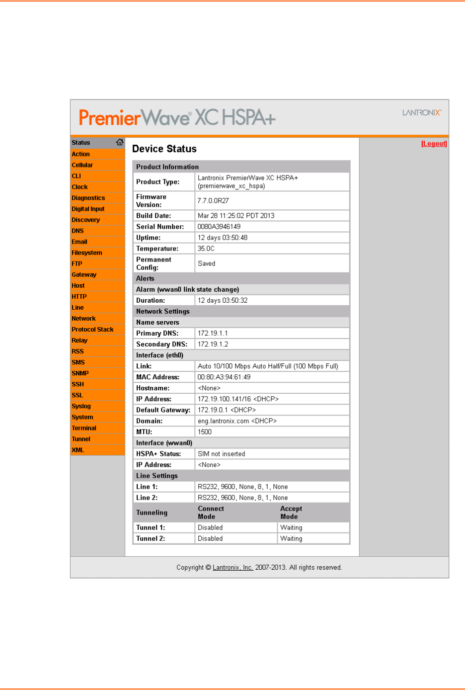
Device Status Page
The Device Status page is the first to appear after you log into Web Manager. The Device Status
page also appears when you click Status in Web Manager.
Figure 5-1 PremierWave XC HSPA+ Home Pages
Note: The Logout button is available on any web page. Logging out of the web page
forces re-authentication the next time the web page is accessed.
PRELIMINARY DRAFT
PRELIMINARY DRAFT
5: Configuration Using Web Manager
PremierWave XC HSPA+ User Guide 29
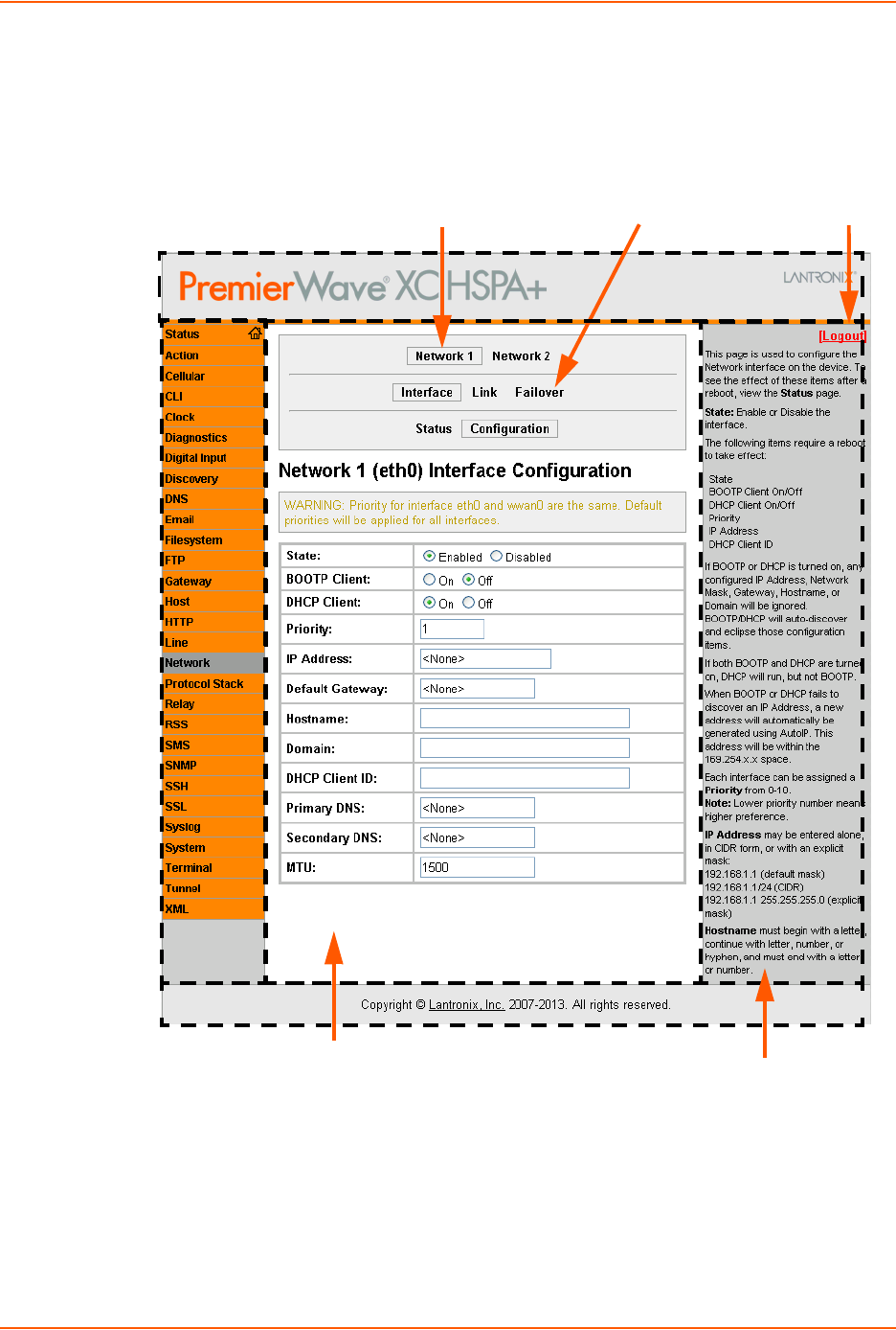
Web Manager Components
The layout of a typical Web Manager page is below.
Figure 5-2 Components of the Web Manager Page
Menu Bar
Links to
subpages
Items to
configure
Header
Information
and Help Area
Configuration and/or Status Area
Footer
Logout
button
PRELIMINARY DRAFT
PRELIMINARY DRAFT

5: Configuration Using Web Manager
PremierWave XC HSPA+ User Guide 30
Web Manager pages have these sections:
The menu bar appears at the left side of the page. The menu bar lists the names of the pages
available. To bring up a page, click it in the menu bar.
Links near the top of many pages, such as the one in the example above, enable you to link to
additional pages. On some pages, you must also select the item you are configuring, such as
a tunnel.
In the middle of many pages, you can select or enter new configuration settings. Some pages
show status or statistics in this area rather than allow you to enter settings.
At the bottom of most pages, the current configuration is displayed. In some cases, you can
reset or clear a setting.
The information or help area shows information or instructions associated with the page.
A Logout link is available at the upper right corner of every page. In Chrome or Safari, it is
necessary to close out of the browser to completely logout. If necessary, reopen the browser
to log back in.
The footer appears at the very bottom of the page. It contains copyright information and a link
to the Lantronix home page.
Navigating Web Manager
The Web Manager provides an intuitive point-and-click interface. A menu bar on the left side of
each page provides links you can click to navigate from one page to another. Some pages are
read-only, while others let you change configuration settings.
Note: There may be times when you must reboot the for the new configuration settings
to take effect. The chapters that follow indicate when a change requires a reboot. Anytime
you reboot the unit, this operation will take some time to complete. Please wait a minimum
of 10-20 seconds after rebooting the unit before attempting to make any subsequent
connections.
Web Manager Page Description See
Page
Status Shows product information, network, , and tunneling settings. 28
Action Allows you to view and configure the actions for a specific alarm or report. 42
Digital Input Allows you to view and configure digital input, shows current input status and
allows you to scale and modify display of both digital inputs.
55
Cellular Shows cellular statistics and lets you change the current CLI configuration
settings.
41
CLI Shows Command Line Interface (CLI) statistics and lets you change the
current CLI configuration settings.
85
Clock Allows you to view and configure the current date, time and time zone as it
displays in web manager.
81
Diagnostics Lets you perform various diagnostic procedures. 78
PRELIMINARY DRAFT
PRELIMINARY DRAFT

5: Configuration Using Web Manager
PremierWave XC HSPA+ User Guide 31
Discovery Allows you to view and modify the configuration and statistics for device
discovery.
83
DNS Shows the current configuration of the DNS subsystem and the DNS cache. 59
Email Shows email statistics and lets you clear the email log, configure email
settings, and send an email.
84
Filesystem Shows file system statistics and lets you browse the file system to view a file,
create a file or directory, upload files using HTTP, copy a file, move a file, or
perform TFTP actions.
73
FTP Shows statistics and lets you change the current configuration for the File
Transfer Protocol (FTP) server.
59
HTTP Shows HyperText Transfer Protocol (HTTP) statistics and lets you change the
current configuration and authentication settings.
61
Network Shows status and lets you configure the network interface. 32
Protocol Stack Lets you perform lower level network stack-specific activities. 75
Query Port Lets you change configuration settings for the query port. 78
Relay Allows you to view and configure relay output, shows current relay output
statuses and allows you to modify display of both relays.
54
RSS Lets you change current Really Simple Syndication (RSS) settings. 63
SNMP Shows and modify the current configuration of SNMP. 64
SSH Lets you change the configuration settings for SSH server host keys, SSH
server authorized users, SSH client known hosts, and SSH client users.
66
SSL Lets you upload an existing certificate or create a new self-signed certificate. 69
Syslog Lets you specify the severity of events to log and the server and ports to
which the syslog should be sent.
60
System Lets you reboot device, restore factory defaults, upload new firmware, and
change the device long and short names.
82
Tunnel Lets you change the current configuration settings for an incoming tunnel
connection.
47
XML Lets you export XML configuration and status records, and import XML
configuration records.
87
Web Manager Page
(continued) Description See
Page
PRELIMINARY DRAFT
PRELIMINARY DRAFT

PremierWave XC HSPA+ User Guide 32
6: Network Settings
The Network Settings show the status of the Ethernet interface/link and let you configure the
settings on the device. Interface settings are related to the configuration of the IP and related
protocols. Link settings are related to the physical link connection, which carries the IP traffic.
The PremierWave contains one network interface. The Ethernet interface is also called interface 1
or eth0.
Notes:
Some settings require a reboot to take effect. These settings are noted below.
Wait a minimum of 10-20 seconds after rebooting the unit before attempting to make
any subsequent connections.
The blue text in the XML command strings of this chapter are to be replaced with a
user-specified name.
Network 1 (eth0) Interface Settings
Table 6-1 shows the network interface settings that can be configured.
Table 6-1 Network Interface Settings
Network Interface
Settings Description
State Select to enable or disable the interface.
BOOTP Client Select to turn On or Off. At boot up, after the physical link is up, the
PremierWave will attempt to obtain IP settings from a BOOTP server.
Note: Overrides the configured IP address/mask, gateway, hostname, and
domain. When DHCP is Enabled, the system automatically uses DHCP,
regardless of whether BOOTP is Enabled. Changing this value requires you to
reboot the device.
DHCP Client Select to turn On or Off. At boot up, after the physical link is up, the
PremierWave will attempt to obtain IP settings from a DHCP server and will
periodically renew these settings with the server.
Note: Overrides BOOTP, the configured IP address/mask, gateway,
hostname, and domain. Changing this value requires you to reboot the device.
Note: Within WebManager, click Renew to renew the DHCP lease.
Priority It ranges from 0-10. Note: Lower priority number means higher preference.
IP Address Enter the static IP address to use for the interface. You may enter it alone or in
CIDR format.
Note: This setting will be used if Static IP is active (both DHCP and BOOTP
are Disabled). Changing this value requires you to reboot the device. When
DHCP or BOOTP is enabled, the PremierWave tries to obtain an IP address
from a DHCP or BOOTP server. If it cannot, the PremierWave generates and
uses an Auto IP address in the range of 169.254.xxx.xxx, with a network mask
of 255.255.0.0.
PRELIMINARY DRAFT
PRELIMINARY DRAFT

6: Network Settings
PremierWave XC HSPA+ User Guide 33
To Configure Network Interface Settings
Using Web Manager
To modify Ethernet (eth0) settings, click Network on the menu and select Network 1 ->
Interface -> Configuration.
Using the CLI
To enter the eth0 command level: enable -> config -> if 1
Using XML
Include in your file: <configgroup name="interface" instance="eth0">
To View Network Interface Status
Using Web Manager
In Network Interface Status, you can view both the current operational settings as well as the
settings that would take affect upon a device reboot.
Default Gateway Enter the IP address of the router for this network.
Note: This setting will be used if Static IP is active (both DHCP and BOOTP
are Disabled).
Hostname Enter the hostname for the interface. It must begin with a letter or number,
continue with a sequence of letters, numbers, or hyphens, and end with a letter
or number.
Note: This setting will take effect immediately, but will not register the
hostname with a DNS server until the next reboot.
Domain Enter the domain name suffix for the interface.
Note: This setting will be used when either Static IP or Auto IP is active, or if
DHCP/BOOTP is active and no Domain Suffix was acquired from the server.
DHCP Client ID Enter the ID if the DHCP server requires a DHCP Client ID option. The DHCP
server’s lease table shows IP addresses and MAC addresses for devices. The
lease table shows the Client ID, in hexadecimal notation, instead of the
PremierWave MAC address.
Primary DNS Enter the IP address of the primary Domain Name Server.
Note: This setting will be used when either Static IP or Auto IP is active, or if
DHCP/BOOTP is active and no DNS server was acquired from the server.
Secondary DNS Enter the IP address of the secondary Domain Name Server.
Note: This setting will be used when either Static IP or Auto IP is active, or if
DHCP/BOOTP is active and no DNS server was acquired from the server.
MTU When DHCP is enabled, the MTU size is (usually) provided with the IP address.
When not provided by the DHCP server, or using a static configuration, this
value is used. The MTU size can be from 576 to 1500 bytes, the default being
1500 bytes.
Network Interface
Settings (continued) Description
PRELIMINARY DRAFT
PRELIMINARY DRAFT

6: Network Settings
PremierWave XC HSPA+ User Guide 34
To view Ethernet (eth0) Status, click Network on the menu and select Network 1 ->
Interface -> Status.
Network 1 (Link) Settings
Physical link parameters can be configured for an Ethernet (eth0) Network Interface (see
Table 6-2).
Table 6-2 Network 1 (eth0) Link Settings
Notes:
When speed is Auto, duplex must be Auto or Half.
When speed is not Auto, duplex must be Half or Full.
Fixed speed Full duplex will produce errors connected to Auto, due to duplex
mismatch.
To Configure Network Link Settings
Using Web Manager
To modify Ethernet (eth0) Link information, click Network on the menu and select Network 1
> Link > Configuration.
Using the CLI
To enter the eth0 Link command level: enable -> config -> if 1 -> link
Using XML
Include in your file: <configgroup name="ethernet" instance="eth0">
Network 1 Ethernet (eth0)
Link Settings Description
Speed Select the Ethernet link speed. (Default is Auto)
Auto = Auto-negotiation of Link Speed
10 Mbps = Force 10 Mbps
100 Mbps = Force 100 Mbps
Duplex Select the Ethernet link duplex mode. (Default is Auto)
Auto = Auto-negotiation of Link Duplex
Half = Force Half Duplex
Full = Force Full Duplex
PRELIMINARY DRAFT
PRELIMINARY DRAFT

6: Network Settings
PremierWave XC HSPA+ User Guide 35
Network 1 (Failover)
PremierWave XC HSPA+ provides basic Ethernet to Cellular failover, in the form of a "dead
remote host reachability" mechanism (essentially a ping against a known host). If the remote host
is determined to be not reachable, the device will failover to the cellular interface. If the remote
host is determined to be reachable, the device will failback to the Ethernet interface.
To Configure Network 1 Failover Settings
Using Web Manager
To modify Failover settings, click Network on the menu and select Network 1 > Failover >
Configuration.
Using the CLI
To enter the eth0 link command level: enable -> config -> if 1 -> failover
Using XML
Include in your file: <configgroup name="network failover" instance="eth0">
Network 2 (Cellular) Settings
This page is used to view the status of the cellular interface on the device.
Note: Statistics are as measured by the device since bootup. Your service provider may
account for data usage differently.
This page is used to configure the Cellular interface on the device. To see the effect of these items
after a reboot, view the Status page.
Network 2 (Failover)
Settings Description
State Click to enable or disable state.
Failover interface Always select wwan0 in PremierWave XC HSPA+.
Hostname Enter the remote host to test reachability.
Ping Protocol Select ICMP or TCP based ping.
Timeout Indicate the interval to wait for ping response from remote host.
Interval Indicate the interval in which to test reachability
Failover Threshold Indicate the allowed number of failed pings – after which the device will
failover to the cellular interface.
Failback Threshold Indicate the number of successful pings – after which the device will failback
to the Ethernet interface.
Network 2 (Cellular
Interface) Settings Description
State Enable or Disable the interface.
Priority It ranges from 0-10. Note: Lower priority number means higher preference.
PRELIMINARY DRAFT
PRELIMINARY DRAFT

6: Network Settings
PremierWave XC HSPA+ User Guide 36
To Configure Network 2 (Cellular Interface) Settings
Using Web Manager
To modify network 2 cellular interface information, click Network on the menu and select
Network 2 > Interface > Configuration.
Using the CLI
To enter the cellular command level: enable -> config -> if 2
Using XML
Include in your file:
<configgroup name = "cellular interface” instance =
“wwan0”>
Network 2 (Link) Settings
This page shows configuration of an Cellular Link on the device.
Connection Mode The Always On connection mode keeps the device always connected to the
cellular network. The On Demand connection mode leaves the link quiescent until
an application attempts to make use of the cellular network connection. Be aware
that in this mode, the first attempt to initiate a connection from the device server
may fail, since a new IP address may need to be negotiated. The Shoulder Tap
connection mode requires a short message (SMS) to make the link active. See
the SMS Inbound configuration for details on the message syntax requirements.
Idle Timeout If the connection mode is 'On Demand' or 'Shoulder Tap' and there is no network
activity for Idle Timeout duration the device will automatically disconnect from the
cellular network.
Primary DNS Enter the IP address of the primary Domain Name Server.
Note: This setting will be used when either Static IP or Auto IP is active, or if
DHCP/BOOTP is active and no DNS server was acquired from the server.
Secondary DNS
Server Enter the IP address of the secondary Domain Name Server.
Note: This setting will be used when either Static IP or Auto IP is active, or if
DHCP/BOOTP is active and no DNS server was acquired from the server.
Network 2 Link
Settings Description
APN (Access Point
Name) Enter the configurable network identifier used by a mobile device when
connecting to a GSM carrier.
Username Enter the Username for dial up to cellular carrier, if required.
Password Enter the Password for dial up to cellular carrier, if required.
Dialup String Enter the modem string used for making connection to carrier.
Roaming Enable or disable the network roaming.
Network 2 (Cellular
Interface) Settings Description
PRELIMINARY DRAFT
PRELIMINARY DRAFT

6: Network Settings
PremierWave XC HSPA+ User Guide 37
To Configure Link Settings
Using Web Manager
To modify network 2 cellular interface information, click Network on the menu and select
Network 2 > Link > Configuration.
Using the CLI
To enter the link command level: enable -> if 2 -> link
Using XML
Include in your file:
<configgroup name = "cellular link" instance = "wwan0">
Gateway
PremierWave XC HSPA+ can be configured as a cellular gateway with DHCP server functionality.
WAN
Table 6-3 WAN Configuration
Gateway Settings Description
Routing Select to enable or disable routing:
Enabled: allows the device to be used as a gateway.
Disabled: prevents the device to be used as a gateway; use the device
normally.
Firewall Select to enable or disable firewall:
Enabled: enables the device firewall.
Disabled: disable the device firewall.
Interface Specify the WAN interface. Generally wwan0 (cellular) interface.
IP Address Assigns a static IP address to the gateway.
Gateway Assigns a static gateway for traffic.
Primary DNS Enter the IP address of the primary Domain Name Server.
Note: This setting will be used when either Static IP or Auto IP is active, or
if DHCP/BOOTP is active and no DNS server was acquired from the
server.
Secondary DNS Enter the IP address of the secondary Domain Name Server.
Note: This setting will be used when either Static IP or Auto IP is active, or
if DHCP/BOOTP is active and no DNS server was acquired from the
server.
PRELIMINARY DRAFT
PRELIMINARY DRAFT

6: Network Settings
PremierWave XC HSPA+ User Guide 38
To Configure Gateway WAN Settings
Using Web Manager
To modify gateway WAN information, click Gateway on the menu and select Configuration >
WAN.
Using the CLI
To enter the gateway command level: enable -> config -> gateway
Using XML
Include in your file:
<configgroup name="ga
teway"> <configitem name="wan">
Port Forwarding
Port forwarding allows remote computers (for example, computers on the Internet) to connect to a
specific computer or service within a private local-area network (LAN). This functionality will not
work if the cellular provider uses NAT.
Table 6-4 Port Forwarding Rules List
Table 6-5 Adding a New Port Forwarding Rule
To Configure Gateway Port Forwarding Settings
Using Web Manager
To modify gateway port forwarding information, click Gateway on the menu and select
Configuration > Port Forwarding.
Port Forwarding Rule Description
Enabled Enables the port forwarding rule.
Delete Deletes the port forwarding rule.
Name User friendly name for the rule. Click on the [Edit] icon to make changes.
Port or Port Range Port or Port range for the rule.
Protocol Protocols for the rule: TCP, UDP, or Both.
IP Address Target for the port forwarding rule.
Adding New Port
Forwarding Rule
Settings
Description
Name User Friendly name for the rule {optional)
Start Port Starting port number
End Port End port number (optional). If start port and end port are same it assumes a
single port. If start port and end port are not the same – it is a port range.
Protocol Protocols for the rule. TCP, UDP, or Both
IP Address Target for the port forwarding rule.
PRELIMINARY DRAFT
PRELIMINARY DRAFT

6: Network Settings
PremierWave XC HSPA+ User Guide 39
Using the CLI
To enter the gateway command level: enable -> config -> gateway -> port
forwarding rule <number>
Using XML
Include in your file: <configgroup name="gateway"> <configitem name="port
forwarding" instance="<number>">
Static Routes
Allows the user to add routes to the device routing table.
Table 6-6 Adding a New Static Route
To Configure Gateway Static Route Settings
Using Web Manager
To modify gateway static route information, click Gateway on the menu and select
Configuration > Static Routes.
Using the CLI
To enter the gateway command level: enable -> config -> gateway -> static
route <number>
Using XML
Include in your file:
<configgroup name ="gateway">
<configitem name="static
routes" instance="<number>">
Static Route Settings Description
Enabled Enables the static route
Delete Deletes the static route
Name User friendly name for the route. Click on the [Edit] icon to make changes.
Route Network or Host for the route
Applied If the route was successfully applied. Routing table updates require a
reboot and route needs to be valid as per other device configurables.
Adding New Static Route
Settings Description
Name User friendly name for the route
Network Network or Host for the route
Gateway Gateway for the route
Interface Interface for the route
Metric Priority for the route. Lower metric means higher priority.
PRELIMINARY DRAFT
PRELIMINARY DRAFT

6: Network Settings
PremierWave XC HSPA+ User Guide 40
DHCP Server
Allows the user to configure the device as a DHCP server.
Table 6-7 DHCPSettings
To Configure Gateway DHCP Server Settings
Using Web Manager
To modify gateway DHCP server information, click Gateway on the menu and select
Configuration > DHCP Server.
Using the CLI
To enter the gateway command level: enable -> config -> gateway -> dhcp
server
Using XML
Include in your file:
<configgroup name = "dhcp server">
Table 6-8 Static Lease Listing
Table 6-9 Add a Static Lease
DHCP Settings Description
State Enable or Disable the DHCP server
Enabled: DHCP server is enabled
Disabled: DHCP server is disabled.
Start IP Address Start IP Address of address pool
End IP Address End IP Address of address pool
Lease time Duration for which lease is initially assigned. Clients must renew after this
duration.
Static Lease List Settings Description
Delete Click checkbox beside existing static lease MAC Address/IP Address to
delete, if available and if desired.
MAC Address MAC Address of existing static leases are listed here.
IP Address Static IP Address of existing static leases are listed here.
Add a Static Lease
Settings Description
MAC Address Enter the MAC Address of the static lease to be added.
IP Address Enter static ip address of the static lease to be added.
PRELIMINARY DRAFT
PRELIMINARY DRAFT

PremierWave XC HSPA+ User Guide 41
7: Cellular
The Cellular page displays the configuration and status for the Cellular module.
To Configure Cellular Settings
Using Web Manager
Click Cellular on the menu.
Using the CLI
To enter the cellular command level: enable -> config -> cellular
Using XML
Include in your file:
<configgroup name = "cellular">
Cellular Settings Description
PIN Lock Enable to prevent unauthorized use of the SIM card.
PIN Enter PIN combination to enable PIN Lock. Caution: If you enter the PIN
incorrectly 3 times, the SIM card will lock, and you will need a PIN Unblocking Key
(PUK) to unlock your SIM card. PUK is required to unlock SIM cards that have
become locked following 3 successive incorrect PIN entries. Caution: If you enter
the PUK incorrectly 10 times, the SIM card will be permanently locked and no
longer operable.
Allowed Bands Select the allowed bands, determining the frequency band usage of the device.
Select/Unselect individual bands to restrict the allowed bands to a specific band or
band combination.
PRELIMINARY DRAFT
PRELIMINARY DRAFT

PremierWave XC HSPA+ User Guide 42
8: Action Settings
Actions can be configured for alarms and reports available in the PremierWave.
Alarms and Reports
PremierWave XC HSPA+ updates the action settings page to display and configure the alarms.
The following alarm and report acations are available in PremierWave XC HSPA+:
Eth0 Link State Change
Wwan0 Link State Change
Digital Input 1 State Change
Digital Input 2 State Change
One or more types of “action” can be configured and triggered when an event occurs.
Actions
Table 8-1 contain the configuration options for all the alarms and reports listed above.
Table 8-1 Action Settings
Action Settings Description
Delay Use Delay to defer alarm processing. Alarm actions will not be executed if the cause
is corrected within this time.
Email Use Email to send an email to configured Email recipients. If an Alarm Email profile
number is selected, that email will be sent when the alarm is turned on. The contents
of Alarm Message will be placed into the email body when an alarm email is sent. If
the alarm stays on longer than the Reminder Interval, another alarm email is sent. If
a Normal Email profile number is selected, that email will be sent when the alarm is
turned off. The contents of Normal Message will be placed into the email body when
a normal email is sent. If the alarm stays off longer than the Reminder Interval,
another normal email is sent.
FTP Put Use FTP Put to put a file on configured FTP server. Filename will be used to upload
to remote FTP server. The IP Address or hostname is the FTP server to connect to.
Port number is port on which FTP server is listening on. Use Protocol to connect to
FTP server. FTPS is a SSL encrypted communication channel and SSL Trusted
Authorities must be setup with FTP server SSL certificate. Username is used to
logon to FTP server. If FTP server does not require authentication, use anonymous.
Password is used to logon to FTP server. If FTP server does not require
authentication, a common practice is to use user’s email address. If the alarm stays
on or off longer than the Reminder Interval, another FTP Put is performed. In
Sequential mode, connections will be attempted starting with number 1 until a
connection is successful. In Simultaneous mode, all possible connections will be
made.
PRELIMINARY DRAFT
PRELIMINARY DRAFT

8: Action Settings
PremierWave XC HSPA+ User Guide 43
To Configure Action Settings
Using Web Manager
To modify Action information, click Action on the menu and select a specific action from the
drop-down menu. Alarms and Reports (on page 42) lists the options.
Using the CLI
To enter the link command level: enable -> config -> action -> eth0 link state
change
To enter the link command level: enable -> config -> action -> wwan0 link
state change
Using XML
Include in your file: <configgroup name = "action" instance = "eth0 link
state change">
Include in your file: <configgroup name = "action" instance = "wwan0 link
state change">
HTTP Post Use HTTP Post post to configured HTTP server. The URL appears behind the HTTP
server IP address or hostname. E.g. http://some_http_server/some_url The IP
Address or hostname is the HTTP server to connect to. Port number is the port which
HTTP server is listening on. Use Protocol to connect to HTTP server. HTTPS is a
SSL encrypted communication channel and SSL Trusted Authorities must be setup
withHTTP server SSL certificate. Username used to logon to HTTP server if
authentication is required. Password used to logon to HTTP server if authentication
is required. If the alarm stays on or off longer than the Reminder Interval, another
HTTP Post is performed. In Sequential mode, connections will be attempted starting
with number 1 until a connection is successful. In Simultaneous mode, all possible
connections will be made.
Relay Select a Relay to switch on when this alarm is activated. Select “None” so this alarm
state will have no effect on any Relay.
GPRS Roaming Select GPRS Roaming to enable or disable GPRS roaming when this alarm is on.
Select No Change so this alarm state will have no effect on GPRS roaming.
SMS Use SMS to send SMS to configured Recipient. The contents of Alarm Message will
be placed into the SMS body when an alarm SMS is sent. If the alarm stays on
longer than the Reminder Interval, another alarm SMS is sent. The contents of
Normal Message will be placed into the SMS body when a normal SMS is sent. If the
alarm stays off longer than the Reminder Interval, another normal SMS is sent.
SNMP Trap Use SNMP Trap to send SNMP trap to configured trap destinations. The contents of
Alarm Message are included when an alarm SNMP trap is sent. If the alarm stays on
longer than the Reminder Interval, another alarm SNMP Trap is sent. The contents of
Normal Message are included when a normal SNMP trap is sent. If the alarm stays
off longer than the Reminder Interval, another normal SNMP Trap is sent.
Action Settings Description
PRELIMINARY DRAFT
PRELIMINARY DRAFT

8: Action Settings
PremierWave XC HSPA+ User Guide 44
Digital Input
Table 8-2 contain additional configuration options for Digital Input 1 and Digital Input 2 settings:
Table 8-2 Digital Input Settings
To Configure Digital Input Settings
Using Web Manager
To modify digital input information, click Digital Input on the menu, select either Digital Input
1 or Digital Input 2, and click the Configuration link.
Using the CLI
To enter the digital input command level: enable -> config -> action -> digital
input 1 state change
To enter the digital input command level: enable -> config -> action -> digital
input 2 state change
Using XML
Include in your file: <configgroup name = "action" instance = "digital input
1 state change">
Include in your file: <configgroup name = "action" instance = "digital input
2 state change">
Digital Input Settings Description
Title Fill in Title to customize how the digital input status will appear in the CLI, Web
Manager, and XML status. Leave Title blank for the default title of "Digital Input N",
where N is the digital input number.
Normal State Select Normal State to "Low" or "High". When input state anges, Normal State is
used to compare with the input state. If the states are different, an alarm will be
triggered which is configured under "Action" menu.
PRELIMINARY DRAFT
PRELIMINARY DRAFT

PremierWave XC HSPA+ User Guide 45
9: Line and Tunnel Settings
The PremierWavehas two tunnels through which you may view statistics or configure the Accept
Mode. The Modbus configuration page allows configuration of Modbus servers listening on the
TCP ports. The PremierWave contains two lines . All lines use standard RS232/RS485 serial
ports.
All lines can be configured to operate in the following modes:
RS232
RS485 Full Duplex (also compatible with RS-422)
RS485 Half Duplex, with and without termination impedance
All serial settings such as Baud Rate, Parity, Data Bits, etc, apply to these lines.
Line Settings
The Line Settings allow configuration of the serial lines (ports).
Some settings may be specific to only certain lines. Such settings are noted below.
Table 9-1 Line Configuration Settings
Line Settings Description
Name Enter a name or short description for the line, if desired. By default, there is
no name specified. A name that contains white space must be quoted.
Interface Set the interface type for the Line. The default is RS232 for Lines 1 and 2.
Choices are:
RS232 (Lines 1 and 2 only)
RS485 Full-Duplex (Lines 1 and 2 only)
RS485 Half-Duplex (Lines 1 and 2 only)
Termination Select to Enable or Disable Line Termination. The default is Disable.
Note: This setting is only relevant for Lines 1 and 2 with Interface type RS485
Half-Duplex.
State Select to Enable or Disable the operational state of the Line. The default is
Enable.
Protocol Set the operational protocol for the Line. The default is Tunnel. Choices are:
None
Tunnel = Serial-Network tunneling protocol.
Baud Rate Set the Baud Rate (speed) of the Line. The default is 9600.
Any set speed between 300 and 921600 may be selected: 300, 600, 1200,
2400, 4800, 9600, 19200, 38400, 57600, 115200, 230400, 460800, 921600.
When selecting a Custom baud rate, you may manually enter any value
between 300 and 5000000.
Note: The maximum baud rate in RS232 mode is 1000000 bps. Custom
baud rates are not supported when a line is configured for Command Mode.
Parity Set the Parity of the Line. The default is None.
PRELIMINARY DRAFT
PRELIMINARY DRAFT

9: Line and Tunnel Settings
PremierWave XC HSPA+ User Guide 46
Table 9-2 Line Command Mode Settings
To Configure Line Settings
Note: The following section describes the steps to view and configure Line 1 settings;
these steps apply to other line instances of the device.
Data Bits Set the number of data bits for the Line. The default is 8.
Stop Bits Set the number of stop bits for the Line. The default is 1.
Flow Control Set the flow control for the Line. The default is None.
Xon Char Set Xon Char to be used when Flow Control is set to Software. Prefix decimal
with \ or prefix hexadecimal with 0x or prefix a single control character
<control>.
Xoff Char Set Xoff Char to be used when Flow Control is set to Software. Prefix decimal
with \ or prefix hexadecimal with 0x or prefix a single control character
<control>.
Gap Timer Set the Gap Timer delay to Set the number of milliseconds to pass from the
last character received before the driver forwards the received serial bytes.
By default, the delay is four character periods at the current baud rate
(minimum 1 msec).
Threshold Set the number of threshold bytes which need to be received in order for the
driver to forward received characters.
Line Command
Mode Settings Description
Mode Set the Command Mode state of the Line. When in Command Mode, a CLI session
operates exclusively on the Line. Choices are:
Always
User Serial String
Disabled
Note: In order to enable Command Mode on the Line, Tunneling on the Line must
be Disabled (both Connect and Accept modes). Also, custom baud rates are not
supported in Command Mode.
Wait Time Enter the amount of time to wait during boot time for the Serial String. This timer
starts right after the Signon Message has been set on the Serial Line and applies
only if mode is “Use Serial String”.
Serial String Enter the Text or Binary string of bytes that must be read on the Serial Line during
boot time in order to enable Command Mode. It may contain a time element to
specify a required delay in milliseconds x, formed as {x}. Applies only if mode is
“User Serial String”. It may contain a binary character(s) of the form [x]. For
example, use decimal [12] or hex [0xc].
Echo Serial String Select Enable or Disable for Echo Serial String. Applies only if mode is “User Serial
String”. Select enable to echo received characters backed out on the line while
looking for the serial string.
Signon Message Enter the string of bytes to be sent to the Serial Line during boot time. It may contain
a binary character(s) of the form [x]. For example, use decimal [12] or hex [0xc].
Line Settings
(continued) Description
PRELIMINARY DRAFT
PRELIMINARY DRAFT

9: Line and Tunnel Settings
PremierWave XC HSPA+ User Guide 47
Using Web Manager
To configure a specific line, click Line in the menu and select Line 1 -> Configuration (Table
9-1).
To configure a specific line in Command Mode, click Line in the menu and select Line 1 ->
Command Mode (Table 9-2).
Using the CLI
To enter Line 1 command level: enable -> line 1
Using XML
Include in your file: <configgroup name="line" instance="1">
Include in your file: <configgroup name="serial command mode" instance="1">
To View Line Statistics
Using Web Manager
To view statistics for a specific line, click Line in the menu and select Line 1 -> Statistics.
Using the CLI
To view Line statistics: enable -> line 1, show statistics
Using XML
Include in your file: <statusgroup name=”line” instance=”1”>
Tunnel Settings
Tunneling allows serial devices to communicate over a network, without “being aware” of the
devices which establish the network connection between them. Tunneling parameters are
configured using the Tunnel menu and submenus. The Tunnel settings allow you to configure
how the Serial-Network tunneling operates. Tunneling is available on all serial lines. The
connections on one serial line are separate from those on another serial port.
Notes: The following section describes the steps to view and configure Tunnel 1 settings;
these steps apply to other tunnel instances of the device.
Serial Settings
These serial settings for the tunnel apply to the Serial Line interface. The Line Settings and
Protocol are displayed for informational purposes and must be configured from the Line settings.
PRELIMINARY DRAFT
PRELIMINARY DRAFT

9: Line and Tunnel Settings
PremierWave XC HSPA+ User Guide 48
Table 9-3 Tunnel Serial Settings
To Configure Tunnel Serial Settings
Using Web Manager
To configure the Serial Settings for a specific tunnel, click Tunnel in the menu and select
Tunnel 1 -> Serial Settings.
Using the CLI
To enter Tunnel 1 command level: enable -> tunnel 1 -> serial
Using XML
Include in your file: <configgroup name=”tunnel serial” instance=”1”>
Packing Mode
With Packing, data from the serial Line is not sent over the network immediately. Instead, data is
queued and sent in segments, when either the timeout or byte threshold is reached. Packing
applies to both Accept and Connect Modes.
Table 9-4 Tunnel Packing Mode Settings
Tunnel Serial
Settings Description
Line Settings Line Settings information here is display only. Go to the section, To Configure
Line Settings to modify these settings.
Protocol Protocol information here is display only. Go to the section, To Configure
Line Settings to modify these settings.
DTR Select the conditions in which the Data Terminal Ready (DTR) control signal
on the serial line are asserted. Choices are:
Unasserted
TruPort = the DTR is asserted whenever either a connect or an accept
mode tunnel connection is active with the Telnet Protocol RFC2217 saying
that the remote DSR is asserted.
Asserted while connected = the DTR is asserted whenever either a
connect or an accept mode tunnel connection is active.
Continuously asserted
Tunnel Packing Mode
Settings Description
Mode Configure the Tunnel Packing Mode. Choices are:
Disable = Data not packed.
Timeout = data sent after timeout occurs.
Send Character = data sent when the Send Character is read on the Serial
Line.
Threshold Set the threshold (byte count). If the received serial data reaches this
threshold, then the data will be sent on the network. Valid range is 100 to
1450 bytes. Default is 512.
PRELIMINARY DRAFT
PRELIMINARY DRAFT

9: Line and Tunnel Settings
PremierWave XC HSPA+ User Guide 49
To Configure Tunnel Packing Mode Settings
Using Web Manager
To configure the Packing Mode for a specific tunnel, click Tunnel in the menu and select
Tunnel 1 -> Packing Mode.
Using the CLI
To enter the Tunnel 1 Packing command level: enable -> tunnel 1 -> packing
Using XML
Include in your file: <configgroup name="tunnel packing" instance="1">
Accept Mode
In Accept Mode, thePremierWave listens (waits) for incoming connections from the network. A
remote node on the network initiates the connection.
The configurable local port is the port the remote device connects to for this connection.
Table 9-5 Tunnel Accept Mode Settings
Timeout Set the timeout value, in milliseconds, after the first character is received on
the serial line, before data is sent on the network. Valid range is 1 to 30000
milliseconds. Default is 1000.
Send Character Enter Control Characters in any of the following forms:
<control>J
0xA (hexadecimal)
\10 (decimal)
If used, the Send Character is a single printable character or a control
character that, when read on the Serial Line, forces the queued data to be
sent on the network immediately.
Trailing Character Enter Control Characters in any of the following forms:
<control>J
0xA (hexadecimal)
\10 (decimal).
If used, the Trailing Character is a single printable character or a control
character that is injected into the outgoing data stream right after the Send
Character. Disable the Trailing Character by blanking the field (setting it to
<None>).
Tunnel Accept Mode
Settings Description
Mode Set the method used to start a tunnel in Accept mode. Choices are:
Disable = do not accept an incoming connection.
Always = accept an incoming connection (default).
Tunnel Packing Mode
Settings (continued) Description
PRELIMINARY DRAFT
PRELIMINARY DRAFT

9: Line and Tunnel Settings
PremierWave XC HSPA+ User Guide 50
Local Port Set the port number for use as the network local port. The default local port
number:
Tunnel 1 : 10001
Tunnel 2 : 10002
Protocol Select the protocol type for use with Accept Mode:
SSH
SSL
TCP (default protocol)
TCP AES
Telnet
Credentials Specifies the name of the set of RSA and/or DSA certificates and keys to
be used for an SSL connection.
AES Encrypt Key Specify the text or hexadecimal advanced encryption standard (AES) key
for encrypting outgoing data for a TCP AES connection.
AES Decrypt Key Specify the text or hexadecimal AES key for decrypting incoming data for a
TCP AES connection.
TCP Keep Alive Enter the time, in milliseconds, thePremierWave waits during a silent TCP
connection before checking if the currently connected network device is
still on the network. If the unit gets no response after 1 attempt, it drops
the connection. Enter 0 to disable.
Block Network Set whether Block Network is enabled for debugging purposes. Choices
are:
Enabled = if Enabled, incoming characters from the network will not be
processed. Instead, they will be buffered and will eventually flow off the
network side.
Disabled = this is the default setting; incoming characters from the
network will be processed. Any buffered characters are sent first.
Password Enter a password. This password can be up to 31 characters in length and
must contain only alphanumeric characters and punctuation. When set,
clients must send the correct password string to the unit within 30 seconds
from opening network connection in order to enable data transmission.
The password sent to the unit must be terminated with one of the following:
0A (Line Feed)
00 (Null)
0D 0A (Carriage Return/Line Feed)
0D 00 (Carriage Return/Null)
If, Prompt for Password is set to Enabled and a password is provided,
the user will be prompted for the password upon connection.
Prompt for Password Select Enabled or Disabled (to enable or disable). This option will only
appear if a password is specified above.
Email on Connect Select an email profile number to which an email notification will be sent
upon the establishment of an accept mode tunnel.
Email on Disconnect Select an email profile number to which an email notification will be sent
upon the disconnection of an accept mode tunnel.
Tunnel Accept Mode
Settings (continued) Description
PRELIMINARY DRAFT
PRELIMINARY DRAFT

9: Line and Tunnel Settings
PremierWave XC HSPA+ User Guide 51
To Configure Tunnel Accept Mode Settings
Using Web Manager
To configure the Accept Mode for a specific tunnel, click Tunnel in the menu and select
Tunnel 1 -> Accept Mode.
Using the CLI
To enter Tunnel 1 Accept Mode command level: enable -> tunnel 1 -> accept
Using XML
Include in your file: <configgroup name="tunnel accept" instance="1">
Connect Mode
In Connect Mode, the PremierWave continues to attempt an outgoing connection on the network,
until established. If the connection attempt fails or the connection drops, then it retries after a
timeout. The remote node on the network must listen for the Connect Mode’s connection.
For Connect Mode to function, it must be enabled, have a remote station (node) configured, and a
remote port configured (TCP or UDP). When established, Connect Mode is always on. Enter the
remote station as an IP address or DNS name. The PremierWave will not make a connection
unless it can resolve the address.
For Connect Mode using UDP, the PremierWave accepts packets from any device on the
network. It will send packets to the last device that sent it packets.
Note: The Port in Connect Mode is not the same port configured in Accept Mode.
The TCP keepalive time is the time in which probes are periodically sent to the other end of the
connection. This ensures the other side is still connected.
Table 9-6 Tunnel Connect Mode Settings
Tunnel Connect Mode
Settings Description
Mode Set the method to be used to attempt a connection to a remote host or device.
Choices are:
Disable = an outgoing connection is never attempted. (default)
Always = a connection is attempted until one is made. If the connection gets
disconnected, the retries until it makes a connection.
Any Character = a connection is attempted when any character is read on
the serial line.
Start Character = a connection is attempted when the start character for the
selected tunnel is read on the serial line.
Modem Control Asserted = a connection is attempted as long as the
Modem Control pin (DSR) is asserted, until a connection is made.
Modem Emulation = a connection is attempted when triggered by modem
emulation AT commands.
Local Port Enter an alternative Local Port. The Local Port is set to <Random> by default
but can be overridden. Blank the field to restore the default.
PRELIMINARY DRAFT
PRELIMINARY DRAFT

9: Line and Tunnel Settings
PremierWave XC HSPA+ User Guide 52
To Configure Tunnel Connect Mode Settings
Using Web Manager
To configure the Connect Mode for a specific tunnel, click Tunnel in the menu and select
Tunnel 1 -> Connect Mode.
Using the CLI
To enter the Tunnel 1 Connect Mode command level: enable -> tunnel 1 -> connect
Using XML
Include in your file: <configgroup name="tunnel connect" instance="1">
Disconnect Mode
Specifies the optional conditions for disconnecting any Accept Mode or Connect Mode connection
that may be established. If any of these conditions are selected but do not occur and the network
disconnects to the device, a Connect Mode connection will attempt to reconnect. However, if none
of these conditions are selected, a closure from the network is taken as a disconnect.
Host 1 Click on the displayed information to expand it for editing. If <None> is
displayed, clicking it will allow you to configure a new host. At least one Host is
required to enable Connect Mode as this information is necessary to connect to
that host.
Reconnect Timer Set the value of the reconnect timeout (in milliseconds) for outgoing connections
established by the device. Valid range is 1 to 65535 milliseconds. Default is
15000.
Flush Serial Data Set whether the serial Line data buffer is flushed upon a new network
connection. Choices are:
Enabled = serial data buffer is flushed on network connection
Disabled = serial data buffer is not flushed on network connection (default)
Block Serial Set whether Block Serial is enabled for debugging purposes. Choices are:
Enabled = If Enabled, incoming characters from the Serial Line will not be
forwarded to the network. Instead, they will be buffered and will eventually
flow off the Serial Line if hardware or software flow control is configured.
Disabled = this is the default setting; incoming characters from the Serial Line
are sent on into the network. Any buffered characters are sent first.
Block Network Set whether Block Network is enabled for debugging purposes. Choices are:
Enabled = If Enabled, incoming characters from the network will not be
forwarded to the Serial Line. Instead, they will be buffered and will eventually
flow off the network side.
Disabled = this is the default setting; incoming characters from the network
are sent on into the Serial Line. Any buffered characters are sent first.
Email on Connect Select an email profile number to which an email notification will be sent upon
the establishment of an accept mode tunnel.
Email on Disconnect Select an email profile number to which an email notification will be sent upon
the disconnection of an accept mode tunnel.
Tunnel Connect Mode
Settings (continued) Description
PRELIMINARY DRAFT
PRELIMINARY DRAFT

9: Line and Tunnel Settings
PremierWave XC HSPA+ User Guide 53
Table 9-7 Tunnel Disconnect Mode Settings
To Configure Tunnel Disconnect Mode Settings
Using Web Manager
To configure the Disconnect Mode for a specific tunnel, click Tunnel in the menu and select
Tunnel 1 -> Disconnect Mode.
Using the CLI
To enter the Tunnel 1 Disconnect command level: enable -> tunnel 1 -> disconnect
Using XML
Include in your file: <configgroup name=”tunnel disconnect” instance=”1”>
Modem Emulation
Some older equipment is designed to attach to a serial port and dial into a network with a modem.
This equipment uses AT commands to control the connection. For compatibility with these older
devices on modern networks, our product mimics the behavior of the modem.
Table 9-8 Tunnel Modem Emulation Settings
Tunnel Disconnect
Mode Settings Description
Stop Character Enter the Stop Character which when received on the Serial Line, disconnects the
tunnel. The Stop Character may be designated as a single printable character or
as a control character. Control characters may be input in any of the following
forms: <control>J or 0xA(hexadercimal) or \10 (decimal). Disable the Stop
Character by blanking the field to set it to <None>.
Modem Control Set whether Modem Control enables disconnect when the Modem Control pin is not
asserted on the Serial Line. Choices are:
Enabled
Disabled (default)
Timeout Enter the number of milliseconds a tunnel may be idle before disconnection. The
value of zero disables the idle timeout.
Flush Serial Data Set whether to flush the Serial Line when the Tunnel is disconnected. Choices are:
Enabled
Disabled (default)
Tunnel Modem
Emulation Settings Description
Echo Pluses Set whether the pluses will be echoed back during a “pause +++ pause” escape
sequence on the Serial Line. Choices are:
Enabled
Disabled (default)
PRELIMINARY DRAFT
PRELIMINARY DRAFT

9: Line and Tunnel Settings
PremierWave XC HSPA+ User Guide 54
To Configure Tunnel Modem Emulation Settings
Using Web Manager
To configure the Modem Emulation for a specific tunnel, click Tunnel in the menu and select
Tunnel 1 -> Modem Emulation.
Using the CLI
To enter the Tunnel 1 Modem command level: enable -> tunnel 1 -> modem
Using XML
Include in your file: <configgroup name=”tunnel modem” instance=”1”>
Echo Commands Set whether characters read on the Serial Line will be echoed, while the Line is in
Modem Command Mode. Choices are:
Enabled
Disabled (default)
Verbose Response Set whether Modem Response Codes are sent out on the Serial Line. Choices are:
Enabled
Disabled (default)
Response Type Select a representation for the Modem Response Codes sent out on the Serial
Line. Choices are:
Text (ATV1) (default)
Numeric (ATV0)
Error Unknown
Commands Set whether the Error Unknown Commands is enabled (ATU0) and ERROR is
returned on the Serial Line for unrecognized AT commands. OTherwise (ATU1)
OK is returned for unrecognized AT commands. Choices are:
Enabled
Disabled (default)
Incoming Connection Set how and if requests are answered after an incoming RING (ATS0=2). Choices
are:
Disabled (default)
Automatic
Manual
Connect String Enter the customized Connect String sent to the Serial Line with the Connect
Modem Response Code.
Display Remote IP Set whether the Display Remote IP is enabled so that the incoming RING sent on
the Serial Line is followed by the IP address of the caller. Choices are:
Enabled
Disabled (default)
Tunnel Modem
Emulation Settings
(continued)
Description
PRELIMINARY DRAFT
PRELIMINARY DRAFT

9: Line and Tunnel Settings
PremierWave XC HSPA+ User Guide 55
Relay Output
Note: When relay is energized/turned on, the relay is closed connecting both relay ports
on the IO connector through the relay. When the relay is turned off, the signal path is
open, disconnecting the relay ports on the IO connector.
Table 9-9 Relay Output Settings
To Configure Relay Settings
Using Web Manager
To configure relay output, go to the Setup tab/page and click Relay > Relay 1 >
Configuration in the menu.
Using the CLI
To enter the relay command level: enable -> config -> relays -> relay
<number>
Using XML
Include in your file: <configgroup name="relay" instance="<number">
Input Settings Description
State Select On or Off whether to display the configuration and status for the Relays.
Title Enter the relay title as it will appear in web manager, XML and CLI. Leave this field
blank to utilize the default “Relay N”, where N is the relay number. For example, you
can name the reading, “Buzzer”, if a buzzer is connected to the PremierWave device.
Latch Enable or disable Latch controls which determine how a relay will be turned off.
Selecting Enabled will require a user to explicitly reset latched relay and then turn it
off.
Selecting Disabled, the relay will automaticaly turn off after any and all of the alarm
triggers are no longer active.
PRELIMINARY DRAFT
PRELIMINARY DRAFT

PremierWave XC HSPA+ User Guide 56
10: Terminal and Host Settings
Predefined connections are available via telnet, ssh, or a serial port. A user can choose one of the
presented options and the device automatically makes the predefined connection.
Either the Telnet, SSH, or serial port connection can present the CLI or the Login Connect Menu.
By default, the CLI is presented when the device is accessed. When configured to present the
Login Connect Menu, the hosts configured via the Host selections, and named serial lines are
presented.
Terminal Settings
You can configure whether each serial line or the telnet/SSH server presents a CLI or a Login
Connect menu when a connection is made.
Table 10-1 Terminal on Network and Line Settings
Terminal on Network
and Line Settings Description
Terminal Type Enter text to describe the type of terminal. The text will be sent to a host via IAC.
Note: IAC means, “interpret as command.” It is a way to send commands over
the network such as send break or start echoing.
Login Connect Menu Select the interface to display when the user logs in. Choices are:
Enabled = shows the Login Connect Menu.
Disabled = shows the CLI (default)
Exit Connect Menu Select whether to display a choice for the user to exit the Login Connect Menu
and reach the CLI. Choices are:
Enabled = a choice allows the user to exit to the CLI.
Disabled = there is no exit to the CLI (default)
Send Break Enter a Send Break control character, e.g., <control> Y, or blank to disable.
When the Send Break control character is received from the network on its way
to the serial line, it is not sent to the line; instead, the line output is forced to be
inactive (the break condition).
Note: This configuration option is only available for Line Terminals.
Break Duration Enter how long the break should last in milliseconds, up to 10000. Default is
500.
Note: This configuration option is only available for Line Terminals.
Echo Select whether to enable echo:
Enabled
Disabled
Note: Applies only to Connect Mode Telnet connections, not to Accept Mode.
Only disable Echo if your terminal echoes, in which case you will see double of
each character typed. Default is enabled.
PRELIMINARY DRAFT
PRELIMINARY DRAFT

10: Terminal and Host Settings
PremierWave XC HSPA+ User Guide 57
To Configure the Terminal Network Connection
Using Web Manager
To configure the Terminal on Network, click Terminal on the menu and select Network ->
Configuration.
To configure the Terminal on Network, click Line 1 on the menu and select Network ->
Configuration.
To configure the Terminal on Network, click Line 2 on the menu and select Network ->
Configuration.
Using the CLI
To enter the Terminal Network command level: enable -> config -> terminal
network
Using XML
Include in your file: <configgroup name=”terminal” instance=”network”>
To Configure the Terminal Line Connection
Note: The following section describes the steps to view and configure Terminal 1
settings; these steps apply to other terminal instances of the device.
Using Web Manager
To configure a particular Terminal Line, click Terminal on the menu and select Line 1 ->
Configuration.
Using the CLI
To enter the Terminal Line command level: enable -> config -> terminal 1
Using XML
Include in your file: <configgroup name=”terminal” instance=”1”>
PRELIMINARY DRAFT
PRELIMINARY DRAFT

10: Terminal and Host Settings
PremierWave XC HSPA+ User Guide 58
Host Configuration
Table 10-2 Host Configuration
To Configure Host Settings
Note: The following section describes the steps to view and configure Host 1 settings;
these steps apply to other host instances of the device.
Using Web Manager
To configure a particular Host, click Host on the menu and select Host 1 -> Configuration.
Using the CLI
To enter the Host command level: enable -> config -> host 1
Using XML
Include in your file: <configgroup name=”host” instance=”1”>
Host Settings Description
Name Enter a name for the host. This name appears on the Login Connect
Menu. To leave a host out of the menu, leave this field blank.
Protocol Select the protocol to use to connect to the host. Choices are:
Telnet
SSH
Note: SSH keys must be loaded or created on the SSH page for the
SSH protocol to work.
SSH Username Appears if you selected SSH as the protocol. Enter a username to
select a pre-configured Username/Password/Key (configured on the
SSH: Client Users page), or leave it blank to be prompted for a
username and password at connect time.
Remote Address Enter an IP address for the host to which the device will connect.
Remote Port Enter the port on the host to which the device will connect.
PRELIMINARY DRAFT
PRELIMINARY DRAFT

PremierWave XC HSPA+ User Guide 59
11: Services Settings
DNS Settings
This section describes the active run-time settings for the domain name system (DNS) protocol.
The primary and secondary DNS addresses come from the active interface. The static addresses
from the Network Interface configuration settings may be overridden by DHCP.
Note: The blue text in the XML command strings of this chapter are to be replaced with
a user-specified name.
Table 11-1 DNS Settings
To View or Configure DNS Settings:
Using Web Manager
To view DNS current status, click DNS in the menu.
To lookup DNS name or IP address, click DNS in the menu to access the Lookup field.
Note: To configure DNS for cases where it is not supplied by a protocol, click Network
in the menu and select Interface -> Configuration.
Using the CLI
To enter the DNS command level: enable -> dns
Using XML
Include in your file: <configgroup name=”interface” instance=”eth0”>
FTP Settings
The FTP protocol can be used to upload and download user files, and upgrade the PremierWave
firmware. A configurable option is provided to enable or disable access via this protocol.
Table 11-2 FTP Settings
Setting / Field Description
Lookup Perform one of the following:
Enter an IP address, and perform a reverse Lookup to locate the hostname for
that IP address
Enter a hostname, and perform a forward Lookup to locate the corresponding IP
address
FTP Settings Description
State Select to enable or disable the FTP server:
Enabled (default)
Disabled
PRELIMINARY DRAFT
PRELIMINARY DRAFT

11: Services Settings
PremierWave XC HSPA+ User Guide 60
To Configure FTP Settings
Using Web Manager
To configure FTP, click FTP in the menu.
Using the CLI
To enter the FTP command level: enable -> config -> ftp
Using XML
Include in your file: <configgroup name=”ftp server”>
Syslog Settings
The Syslog information shows the current configuration and statistics of the syslog. Here you can
configure the syslog host and the severity of the events to log.
Note: The system log is always saved to local storage, but it is not retained through
reboots unless diagnostics logging to the filesystem is enabled. Saving the system log to a
server that supports remote logging services (see RFC 3164) allows the administrator to
save the complete system log history. The default port is 514.
Table 11-3 Syslog Settings
To View or Configure Syslog Settings:
Using Web Manager
To configure the Syslog, click Syslog in the menu.
Using the CLI
To enter the Syslog command level: enable -> config -> syslog
Syslog Settings Description
State Select to enable or disable the syslog:
Enabled
Disabled (default)
Host Enter the IP address of the remote server to which system logs are sent for storage.
Remote Port Enter the number of the port on the remote server that supports logging services.
The default is 514.
Severity Log Level Specify the minimum level of system message the PremierWave should log. This
setting applies to all syslog facilities. The drop-down list in the Web Manager is in
descending order of severity (e.g., Emergency is more severe than Alert.)
PRELIMINARY DRAFT
PRELIMINARY DRAFT

11: Services Settings
PremierWave XC HSPA+ User Guide 61
Using XML
Include in your file: <configgroup name=”syslog”>
HTTP Settings
Hypertext Transfer Protocol (HTTP) is the transport protocol for communicating hypertext
documents on the Internet. HTTP defines how messages are formatted and transmitted. It also
defines the actions web servers and browsers should take in response to different commands.
HTTP Authentication enables the requirement of usernames and passwords for access to the
device.
Table 11-4 HTTP Settings
HTTP Settings Description
State Select to enable or disable the HTTP server:
Enabled (default)
Disabled
Port Enter the port for the HTTP server to use. The default is 80.
Secure Port Enter the port for the HTTPS server to use. The default is 443. The HTTP
server only listens on the HTTPS Port when an SSL certificate is configured.
Secure Protocols Select to enable or disable the following protocols:
SSL3 = Secure Sockets Layer version 3
TLS1.0 = Transport Layer Security version 1.0. TLS 1.0 is the successor of
SSL3 as defined by the IETF.
TLS1.1 = Transport Layer Security version 1.1
The protocols are enabled by default.
Note: A server certificate and associated private key need to be installed in
the SSL configuration section to use HTTPS.
Secure Credentials Specify the name of the set of RSA and/or DSA certificates and keys to be
used for the secure connection.
Max Timeout Enter the maximum time for the HTTP server to wait when receiving a
request. This prevents Denial-of-Service (DoS) attacks. The default is 10
seconds.
Max Bytes Enter the maximum number of bytes the HTTP server accepts when receiving
a request. The default is 40 KB (this prevents DoS attacks).
Note: You may need to increase this number in some cases where the
browser is sending data aggressively within TCP windows size limit, when file
(including firmware upgrade) is uploaded from webpage.
Logging State Select to enable or disable HTTP server logging:
Enabled (default)
Disabled
Max Log Entries Set the maximum number of HTTP server log entries. Only the last Max Log
Entries are cached and viewable.
PRELIMINARY DRAFT
PRELIMINARY DRAFT

11: Services Settings
PremierWave XC HSPA+ User Guide 62
To Configure HTTP Settings
Using Web Manager
To configure HTTP settings, click HTTP in the menu and select Configuration.
To view HTTP statistics, click HTTP in the menu and select Statistics.
Using the CLI
To enter the HTTP command level: enable -> config -> http
Using XML
Include in your file: <configgroup name=”http server”>
Table 11-5 HTTP Authentication Settings
Log Format Set the log format string for the HTTP server. Follow these Log Format rules:
%a - remote IP address (could be a proxy)
%b - bytes sent excluding headers
%B - bytes sent excluding headers (0 = '-')
%h - remote host (same as '%a')
%{h}i - header contents from request (h = header string)
%m - request method
%p - ephemeral local port value used for request
%q - query string (prepend with '?' or empty '-')
%t - timestamp HH:MM:SS (same as Apache '%(%H:%M:%S)t' or
'%(%T)t')
%u - remote user (could be bogus for 401 status)
%U - URL path info
%r - first line of request (same as '%m %U%q <version>')
%s - return status
Authentication Timeout The timeout period applies if the selected authentication type is either Digest
or SSL/Digest. After this period of inactivity, the client must authenticate
again.
HTTP Authentication
Settings Description
URI Enter the Uniform Resource Identifier (URI).
Note: The URI must begin with ‘/’ to refer to the filesystem.
Auth Type Select the authentication type:
None = no authentication is necessary.
Basic = encodes passwords using Base64.
Digest = encodes passwords using MD5.
SSL = can only be accessed over SSL (no password is required).
SSL/Basic = is accessible only over SSL and encodes passwords using Base64.
SSL/Digest = is accessible only over SSL and encodes passwords using MD5.
Note: When changing the parameters of Digest or SSL Digest authentication, it is
often best to close and reopen the browser to ensure it does not attempt to use
cached authentication information.
HTTP Settings (continued) Description
PRELIMINARY DRAFT
PRELIMINARY DRAFT

11: Services Settings
PremierWave XC HSPA+ User Guide 63
To Configure HTTP Authentication
Using Web Manager
To configure HTTP Authentication, click HTTP in the menu and select Authentication.
Using the CLI
To enter the HTTP command level: enable -> config -> http
Using XML
Include in your file: <configgroup name=”http authentication uri”
instance=”uri name”>
RSS Settings
Really Simple Syndication (RSS) (sometimes referred to as Rich Site Summary) is a method of
feeding online content to Web users. Instead of actively searching for configuration changes, RSS
feeds permit viewing only relevant and new information regarding changes made via an RSS
publisher. The RSS feeds may also be stored to the file system cfg_log.txt file.
Table 11-6 RSS Settings
To Configure RSS Settings
Using Web Manager
To configure RSS, click RSS in the menu.
Using the CLI
To enter the RSS command level: enable -> config -> rss
Using XML
Include in your file: <configgroup name=”rss”>
RSS Settings Description
RSS Feed Select On or Off for RSS feeds to an RSS publisher. The default setting is off.
Persistent Select On or Off for RSS feed to be written to a file (cfg_log.txt) and to be available
across reboots. The default setting is off.
Max Entries Set the maximum number of log entries. Only the last Max Entries are cached and
viewable.
View Click the button to view RSS feeds.
Clear Click the button to clear RSS feed data.
PRELIMINARY DRAFT
PRELIMINARY DRAFT

11: Services Settings
PremierWave XC HSPA+ User Guide 64
SNMP Settings
Simple Network management Protocol (SNMP) settings may be viewed and configured in this
section.
Table 11-7 SNMP Settings
To Configure SNMP Settings
Using Web Manager
To configure SNMP, click SNMP in the menu.
Using the CLI
To enter the SNMP command level: enable -> config -> snmp
Using XML
Include in your file: <configgroup name=”snmp”>
SMS
Allows the user to view and configure inbound/outbound SMS to/from the device.
Inbound SMS
Table 11-8 Inbound SMS Settings
RSS Settings Description
System Location Specify a system location for the SNMP setting.
Primary Destination Specify SNMP trap primary destination.
Secondary
Destination Specify SNMP trap secondary destination.
Community Specify SNMP trap community.
Inbound SMS Settings Description
Delete Click beside an existing SMS Sender Configuration to delete it.
Number Enter the sender number of a new SMS Sender to add.
Shoulder Tap Check to allow incoming SMS with content containing ‘shoulder tap’ from this
sender to start the cellular interface.
Relay Control Check to allow incoming SMS with content containing ‘relay N On/Off’ from this
sender to open and close the device relays.
PRELIMINARY DRAFT
PRELIMINARY DRAFT

11: Services Settings
PremierWave XC HSPA+ User Guide 65
Outbound SMS
Table 11-9 Outbound SMS Settings
To Configure SMS
Using Web Manager
To view and configure inbound SMS, click SMS in the menu and select Inbound.
Using the CLI
To enter the command level: enable -> configure -> sms -> inbound
Using the XML
Include in your file: <configgroup name="sms inbound">
To Configure Outbound SMS
Using Web Manager
To view and configure outbound SMS, click SMS in the menu and select Outbound
Using the CLI
To enter the command level: enable -> configure -> sms -> outbound
Using the XML
Include in your file: <configgroup name="sms outbound">
Outbound SMS Settings Description
Message Center Default
Number Displays the Message Center number as configured in the SIM.
Message Center
Override Number Enter a number to override the existing Message Center number.
Band Select a band from the drop-down menu:
GSM only
GPRS only
GSM preferred
GPRS preferred.
Number Enter the Recipient Number.
Mode Select the SMS encoding mode:
ASCII 7-bit
ASCII 8-bit
UCS-2
Message Enter the SMS message content.
PRELIMINARY DRAFT
PRELIMINARY DRAFT

PremierWave XC HSPA+ User Guide 66
12: Security Settings
The PremierWave XC HSPA+ device supports Secure Shell (SSH) and Secure Sockets Layer
(SSL). SSH is a network protocol for securely accessing a remote device. SSH provides a secure,
encrypted communication channel between two hosts over a network. It provides authentication
and message integrity services.
Secure Sockets Layer (SSL) is a protocol that manages data transmission security over the
Internet. It uses digital certificates for authentication and cryptography against eavesdropping and
tampering. It provides encryption and message integrity services. SSL is widely used for secure
communication to a web server. SSL uses certificates and private keys.
Note: The device supports SSLv3 and its successors, TLS1.0 and TLS1.1. An incoming
SSLv2 connection attempt is answered with an SSLv3 response. If the initiator also
supports SSLv3, SSLv3 handles the rest of the connection.
SSH Settings
SSH is a network protocol for securely accessing a remote device over an encrypted channel. This
protocol manages the security of internet data transmission between two hosts over a network by
providing encryption, authentication, and message integrity services.
Two instances require configuration: when the PremierWave is the SSH server and when it is an
SSH client. The SSH server is used by the CLI (Command Mode) and for tunneling in Accept
Mode. The SSH client is for tunneling in Connect Mode.
To configure the PremierWave as an SSH server, there are two requirements:
Defined Host Keys: both private and public keys are required. These keys are used for the
Diffie-Hellman key exchange (used for the underlying encryption protocol).
Defined Users: these users are permitted to connect to the PremierWave SSH server.
SSH Server Host Keys
The SSH Server Host Keys are used by all applications that play the role of an SSH Server.
Specifically Tunneling in Accept Mode. These keys can be created elsewhere and uploaded to the
device or automatically generated on the device.
If uploading existing keys, take care to ensure the Private Key will not be compromised in transit.
This implies the data is uploaded over some kind of secure private network.
Note: Some SSH Clients require RSA Host Keys to be at least 1024 bits in size.
Table 12-1 SSH Server Host Keys
RSS Settings Description
Private Key Enter the path and name of the existing private key you want to upload. In
WebManager, you can also browse to the private key to be uploaded. Be sure the
private key will not be compromised in transit. This implies the data is uploaded over
some kind of secure private network.
PRELIMINARY DRAFT
PRELIMINARY DRAFT

12: Security Settings
PremierWave XC HSPA+ User Guide 67
Note: SSH Keys from other programs may be converted to the required PremierWave
format. Use Open SSH to perform the conversion.
SSH Client Known Hosts
The SSH Client Known Hosts are used by all applications that play the role of an SSH Client.
Specifically in Connect Mode. Configuring these public keys are optional but if they exist another
layer of security is offered which helps prevent Man-in-the-Middle (MITM) attacks.
Table 12-2 SSH Client Known Hosts
Note: These settings are not required for communication. They protect against Man-In-
The-Middle (MITM) attacks.
SSH Server Authorized Users
The SSH Server Authorized Users are used by all applications that play the role of an SSH Server
and specifically Tunneling in Accept Mode. Every user account must have a Password.
The user's Public Keys are optional and only necessary if public key authentication is wanted.
Using public key authentication will allow a connection to be made without the password being
asked at that time.
Note: When uploading the security keys, ensure the keys are not compromised in
transit.
Public Key Enter the path and name of the existing public key you want to upload. In
WebManager, you can also browse to the public key to be uploaded.
Key Type Select a key type to use for the new key:
RSA
DSA
Bit Size Select a bit length for the new key:
512
768
1024
RSS Settings Description
Server Specify either a DNS Hostname or IP Address when adding public host keys for a
Server. This Server name should match the name used as the Remote Address in
Connect Mode Tunneling.
Public RSA Key Enter the path and name of the existing public RSA key you want to use with this
user. In WebManager, you can also browse to the public RSA key to be uploaded. If
authentication is successful with the key, no password is required.
Public DSA Key Enter the path and name of the existing public DSA key you want to use with this
user. In WebManager, you can also browse to the public DSA key to be uploaded.If
authentication is successful with the key, no password is required.
RSS Settings
(continued) Description
PRELIMINARY DRAFT
PRELIMINARY DRAFT

12: Security Settings
PremierWave XC HSPA+ User Guide 68
Table 12-3 SSH Server Authorized Users
SSH Client Users
The SSH Client Users are used by all applications that play the role of an SSH Client. Specifically
Tunneling in ConnectA Mode. To configure the PremierWave as an SSH client, an SSH client
user must be both configured and also exist on the remote SSH server.
At the very least, a Password or Key Pair must be configured for a user. The keys for public key
authentication can be created elsewhere and uploaded to the device or automatically generated
on the device.
If uploading existing Keys, take care to ensure the Private Key will not be compromised in transit.
This implies the data is uploaded over some kind of secure private network.
The default Remote Command is '<Default login shell>' which tells the SSH Server to execute a
remote shell upon connection. This can be changed to anything the SSH Server on the remote
host can execute.
Note: If you are providing a key by uploading a file, make sure that the key is not
password protected.
Table 12-4 SSH Client Users
RSS Settings Description
Username Enter a new username or edit an existing one.
Password Enter a new password or edit an existing one.
Public RSA Key Enter the path and name of the existing public RSA key you want to use with this
user. In WebManager, you can also browse to the public RSA key to be uploaded. If
authentication is successful with the key, no password is required.
Public DSA Key Enter the path and name of the existing public DSA key you want to use with this
user. In WebManager, you can also browse to the public DSA key to be uploaded.If
authentication is successful with the key, no password is required.
RSS Settings Description
Username Enter the name that the device uses to connect to an SSH server.
Password Enter the password associated with the username.
Remote Command Enter the command that can be executed remotely. Default is shell, which tells the
SSH server to execute a remote shell upon connection. This command can be
changed to anything the remote host can perform.
Private Key Enter the path and name of the existing private key you want to upload. In
WebManager, you can also browse to the private key to be uploaded. Be sure the
private key will not be compromised in transit. This implies the data is uploaded over
some kind of secure private network.
Public Key Enter the path and name of the existing public key you want to upload. In
WebManager, you can also browse to the public key to be uploaded.
Key Type Select a bit length for the key:
RSA
DSA
PRELIMINARY DRAFT
PRELIMINARY DRAFT

12: Security Settings
PremierWave XC HSPA+ User Guide 69
To Configure SSH Settings
Using Web Manager
To configure SSH, click SSH in the menu.
Using the CLI
To enter the SSH command level: enable -> ssh
Using XML
SSL Settings
Secure Sockets Layer (SSL) is a protocol for managing the security of data transmission over the
Internet. It provides encryption, authentication, and message integrity services. SSL is widely used
for secure communication to a web server.
Certificate/Private key combinations can be obtained from an external Certificate Authority (CA)
and uploaded into the unit. Self-signed certificates with associated private key can be generated
by the device server itself.
Note: The blue text in the XML command strings of this chapter are to be replaced with
a user-specified name.
Certificate and Key Generation
The PremierWave can generate self signed certificates and their corresponding keys. This can be
done for both the rsa and dsa certificate formats. Certificates can be identified on the
PremierWave by a name provided at generation time.
Bit Size Select the bit length of the new key:
512
768
1024
Using a larger Bit Size takes more time to generate the key. Approximate times are:
1 second for a 512 bit RSA key
1 second for a 768 bit RSA key
1 second for a 1024 bit RSA key
2 seconds for a 512 bit DSA key
2 seconds for a 768 bit DSA key
20 seconds for a 1024 bit DSA key
Note: Some SSH clients require RSA host keys to be at least 1024 bits long. This
device generates keys up to 2048 bits long.
RSS Settings
(continued) Description
PRELIMINARY DRAFT
PRELIMINARY DRAFT

12: Security Settings
PremierWave XC HSPA+ User Guide 70
Table 12-5 Certificate and Key Generation Settings
To Create a New Credential
Using Web Manager
To create a new credential, click SSL in the menu and select Credentials.
Using the CLI
To enter the SSL command level: enable -> ssl
To enter the Credentials command level: enable -> ssl -> credentials
Using XML
Not applicable.
Certificate Generation
Settings Description
Country (2 Letter Code) Enter the 2-letter country code to be assigned to the new self-signed
certificate.
Examples: US for United States and CA for Canada
State/Province Enter the state or province to be assigned to the new self-signed certificate.
Locality (City) Enter the city or locality to be assigned to the new self-signed certificate.
Organization Enter the organization to be associated with the new self-signed certificate.
Organization Unit Enter the organizational unit to be associated with the new self-signed
certificate.
Common Name Enter the common name to be associated with the new self signed
certificate, preferrably matching the host name or the ip address of the
device, whichever will be the intended access approach. This is a required
field.
Expires Enter the expiration date, in mm/dd/yyyy format, for the new self-signed
certificate.
Example: An expiration date of May 9, 2012 is entered as 05/09/2012.
Key length Select the bit size of the new self-signed certificate. Choices are:
512 bits
768 bits
1024 bits
2048 bits
The larger the bit size, the longer it takes to generate the key.
Type Select the type of key:
RSA = Public-Key Cryptography algorithm based on large prime
numbers, invented by Rivest Shamir and Adleman. Used for encryption
and signing.
DSA = Digital Signature Algorithm also based on large prime numbers,
but can only be used for signing. Developed by the US government to
avoid the patents on RSA.
PRELIMINARY DRAFT
PRELIMINARY DRAFT

12: Security Settings
PremierWave XC HSPA+ User Guide 71
Certificate Upload Settings
SSL certificates identify the PremierWave to peers. Certificate and key pairs can be uploaded to
the PremierWave through either the CLI or XML import mechanisms. Certificates can be identified
on the PremierWave by a name provided at upload time.
Table 12-6 Upload Certificate Settings
To Configure an Existing SSL Credential
Using Web Manager
To configure an existing SSL Credential, click SSL in the menu and select Credentials.
Using the CLI
To enter the SSL command level: enable -> ssl
To enter the Credential command level: enable -> ssl -> credentials
Using XML
Include in your file:
<configgroup name=”ssl”>
and <configitem name=”credentials” instance=”name”>
and <value name="RSA certificate"/> or <value name="DSA certificate"/>
Upload
Certificate
Settings
Description
New Certificate SSL certificate to be uploaded.
RSA or DSA certificates are allowed.
The format of the certificate must be PEM. It must start with “-----BEGIN
CERTIFICATE-----“ and end with “-----END CERTIFICATE-----“. Some
Certificate Authorities add comments before and/or after these lines. Those need to be
deleted before upload.
New Private Key The key needs to belong to the certificate entered above.
The format of the file must be PEM. It must start with “-----BEGIN RSA
PRIVATE KEY-----” and end with “-----END RSA PRIVATE KEY-----”.
Read DSA instead of RSA in case of a DSA key. Some Certificate Authorities add
comments before and/or after these lines. Those need to be deleted before upload.
PRELIMINARY DRAFT
PRELIMINARY DRAFT

12: Security Settings
PremierWave XC HSPA+ User Guide 72
Trusted Authorities
One or more authority certificates are needed to verify a peer's identity. These certificates do not
require a private key.
To Upload an Authority Certificate
Using Web Manager
To upload an Authority Certificate, click SSL in the menu and select Trusted Authorities.
Using the CLI
To enter the SSL command level: enable -> ssl
To enter the Trusted Authorities command level: enable -> ssl -> trusted
authorities
Using XML
Include in your file:
<configgroup name=”ssl”>
and <configitem name=”trusted authority” instance =”1”>
and <configitem name=”intermediate authority” instance=”1”>
Table 12-7 Trusted Authority Settings
Trusted Authorities
Settings Description
Authority SSL authority certificate.
RSA or DSA certificates are allowed.
The format of the authority certificate can be PEM or PKCS7. PEM files
must start with “-----BEGIN CERTIFICATE-----” and end with “---
--END CERTIFICATE-----”. Some Certificate Authorities add
comments before and/or after these lines. Those need to be deleted
before upload.
Delete Click the Delete button beside a specific certificate authority to delete it.
PRELIMINARY DRAFT
PRELIMINARY DRAFT

PremierWave XC HSPA+ User Guide 73
13: Maintenance and Diagnostics Settings
Filesystem Settings
Use the file system to list, view, add, remove, and transfer files. The PremierWave uses a flash file
system to store files.
File Display
It is possible to view the list of existing files, and to view their contents in the ASCII or hexadecimal
formats.
Table 13-1 File Display Settings
To Display Files
Using Web Manager
To view existing files and file contents, click FIlesystem in the menu and select Browse.
Using the CLI
To enter the Filesystem command level: enable -> filesystem
Using XML
Not applicable.
File Display Commands Description
ls Displays a list of files on the PremierWave, and their respective sizes.
cat Displays the specified file in ASCII format.
dump Displays the specified file in a combination of hexadecimal and ASCII
formats.
pwd Print working directory.
cd Change directories.
show tree Display file/directory tree.
PRELIMINARY DRAFT
PRELIMINARY DRAFT

13: Maintenance and Diagnostics Settings
PremierWave XC HSPA+ User Guide 74
File Modification
The PremierWave allows for the creation and removal of files on its filesystem.
Table 13-2 File Modification Settings
File Transfer
Files can be transferred to and from the PremierWave via the TFTP protocol. This can be useful
for saving and restoring XML configuration files. Files can also be uploaded via HTTP.
Table 13-3 File Transfer Settings
File Modification
Commands Description
rm Removes the specified file from the file system.
touch Creates the specified file as an empty file.
cp Creates a copy of a file.
mkdir Creates a directory on the file system.
rmdir Removes a directory from the file system.
format Format the file system and remove all data.
File Transfer Settings Description
Create Type in a File or Directory name and click the Create button. The newly
created File or Directory will appear above.
Upload File Browse to location of the file to be uploaded.
Copy File Enter the Source and Destination name for file to be copied and click the
Copy button.
Move Enter the Source and Destination name for file to be moved and click the
Move button.
Action Select the action that is to be performed via TFTP:
Get = a “get” command will be executed to store a file locally.
Put = a “put” command will be executed to send a file to a remote
location.
Local File Enter the name of the local file on which the specified “get” or “put” action is
to be performed.
Remote File Enter the name of the file at the remote location that is to be stored locally
(“get’) or externally (“put”).
Host Enter the IP address or name of the host involved in this operation.
Port Enter the number of the port involved in TFTP operations.
PRELIMINARY DRAFT
PRELIMINARY DRAFT

13: Maintenance and Diagnostics Settings
PremierWave XC HSPA+ User Guide 75
To Transfer or Modify Filesystem Files
Using Web Manager
To create a new file or directory, upload an existing file, copy or move a file, click Filesystem
in the menu and select Browse.
Using the CLI
To enter the Filesystem command level: enable -> filesystem
Using XML
Not applicable.
Protocol Stack Settings
There are various low level network stack specific items that are available for configuration. This
includes settings related to IP, ICMP, ARP and SMTP, which are described in the sections below.
IP Settings
Table 13-4 IP Network Stack Settings
To Configure IP Network Stack Settings
Using Web Manager
To configure IP protocol settings, click Protocol Stack in the menu and select IP.
Using the CLI
To enter the command level: enable -> config -> ip
Using XML
Include in your file: <configgroup name=”ip”>
Protocol Stack
IP Settings Description
IP Time to Live This value typically fills the Time To Live in the IP header.
Enter the number of hops to be transmitted before the packet is discarded.
Multicast Time to Live This value fills the Time To Live in any multicast IP header. Normally this value
will be one so the packet will be blocked at the first router. It is the number of
hops allowed before a Multicast packet is discarded.
Enter the value to be greater than one to intentionally propagate multicast
packets to additional routers.
PRELIMINARY DRAFT
PRELIMINARY DRAFT

13: Maintenance and Diagnostics Settings
PremierWave XC HSPA+ User Guide 76
ICMP Settings
Table 13-5 ICMP Network Stack Settings
To Configure ICMP Network Stack Settings
Using Web Manager
To configure ICMP protocol settings, click Protocol Stack in the menu and select ICMP.
Using the CLI
To enter the command level: enable -> config -> icmp
Using XML
Include in your file: <configgroup name=”icmp”>
ARP Settings
Table 13-6 ARP Network Stack Settings
To Configure ARP Network Stack Settings
Using Web Manager
To configure ARP protocol settings, click Protocol Stack in the menu and select ARP.
Using the CLI
To enter the command level: enable -> config -> arp
Using XML
Include in your file: <configgroup name=”arp”>
Protocol Stack
ICMP Settings Description
State The State selection is used to turn on/off processing of ICMP messages.
This includes both incoming and outgoing messages. Choose Enabled or
Disabled.
Protocol Stack
ARP Settings Description
IP Address Enter the IP address to add to the ARP cache.
MAC Address Enter the MAC address to add to the ARP cache.
Remove Click the Remove link beside a specific address to remove it.
Remove All Click the Remove All link underneath all listed addresses to remove all the
addresses.
PRELIMINARY DRAFT
PRELIMINARY DRAFT

13: Maintenance and Diagnostics Settings
PremierWave XC HSPA+ User Guide 77
SMTP Settings
Table 13-7 SMTP Network Stack Settings
To Configure SMTP Network Stack Settings
Using Web Manager
To configure SMTP protocol settings, click Protocol Stack in the menu and select SMTP.
Using the CLI
To enter the command level: enable -> config -> smtp
Using XML
Include in your file: <configgroup name=”smtp”>
To Configure ARP Network Stack Settings
Using Web Manager
To configure SMTP protocol settings, click Protocol Stack in the menu and select SMTP.
Using the CLI
To enter the command level: enable -> config -> smtp
Using XML
Include in your file: <configgroup name=”smtp”>
Protocol Stack SMTP
Settings Description
From Address Enter the From Address here. This is an email address and is required. If you wish
to direct oubtound email messages through a mail server, put your client email
address here.
Server Address Enter the Server Address to direct outbound email messages through a mail
server.
Server Port Enter the SMTP server port number. The default is 25
Username Enter a Username to direct outbound email messages through a mail server.
Password Enter a Password to direct outbound email messages through a mail server.
Overriding Domain Enter the domain name to override the current domain name in EHLO (Extended
Hello).
PRELIMINARY DRAFT
PRELIMINARY DRAFT

13: Maintenance and Diagnostics Settings
PremierWave XC HSPA+ User Guide 78
Diagnostics
The PremierWave has several tools for diagnostics and statistics. Various options allow for the
configuration or viewing of IP socket information, ping, traceroute, memory, and processes.
Hardware
To View Hardware Information
Using Web Manager
To view hardware information, click Diagnostics in the menu and select Hardware.
Using the CLI
To enter the command level: enable -> device, show hardware information
Using XML
Include in your file: <statusgroup name=”hardware”>
IP Sockets
You can view the list of listening and connected IP sockets.
To View the List of IP Sockets
Using Web Manager
To view IP Sockets, click Diagnostics in the menu and select IP Sockets.
Using the CLI
To enter the command level: enable, show ip sockets
Using XML
Include in your file: <statusgroup name=”ip sockets”>
Ping
The ping command can be used to test connectivity to a remote host.
Table 13-8 Ping Settings
Diagnostics: Ping
Settings (continued) Description
Host Enter the IP address or host name for the PremierWave to ping.
Count Enter the number of ping packets PremierWave should attempt to send to the Host.
The default is 5.
Timeout Enter the time, in seconds, for the PremierWave to wait for a response from the
host before timing out. The default is 5 seconds.
PRELIMINARY DRAFT
PRELIMINARY DRAFT

13: Maintenance and Diagnostics Settings
PremierWave XC HSPA+ User Guide 79
To Ping a Remote Host
Using Web Manager
To ping a Remote Host, click Diagnostics in the menu and select Ping.
Using the CLI
To enter the command level: enable, ping <host> <count> <timeout>
Using XML
Not applicable.
Traceroute
Here you can trace a packet from the PremierWave to an Internet host, showing how many hops
the packet requires to reach the host and how long each hop takes. If you visit a web site whose
pages appear slowly, you can use traceroute to determine where the longest delays are occurring.
Table 13-9 Traceroute Settings
To Perform a Traceroute
Using Web Manager
To perform a Traceroute, click Diagnostics in the menu and select Traceroute.
Using the CLI
To enter the command level: enable, trace route <host> <port>
Using XML
Not applicable.
Log
Table 13-10 Log Settings
Diagnostics:
Traceroute Settings Description
Host Enter the IP address or DNS hostname. This address is used to show the path
between it and the PremierWave when issuing the traceroute command.
Protocol Specify the traceroute protocol.
Diagnostics: Log Description
Output Select a diagnostic log output type:
Disable - Turn off the login feature.
Filesystem - Directs logging to /log.txt.Line (1or, 2, ) - Directs logging to the
selected serial line.
PRELIMINARY DRAFT
PRELIMINARY DRAFT

13: Maintenance and Diagnostics Settings
PremierWave XC HSPA+ User Guide 80
To Configure the Diagnostic Log Output
Using Web Manager
To configure the Diagnostic Log output, click Diagnostics in the menu and select Log.
Using the CLI
To enter the command level: enable -> config -> diagnostics -> log
Using XML
Include in your file:
<configgroup name=”diagnostics”>
and
<configitem name=”log”>
Memory
The memory information shows the total, used, and available memory (in kilobytes).
To View Memory Usage
Using Web Manager
To view memory information, click Diagnostics in the menu and select Memory.
Using the CLI
To enter the command level: enable -> device, show memory
Using XML
Include in your file: <statusgroup name=”memory”>
Processes
The PremierWave Processes information shows all the processes currently running on the
system. It shows the Process ID (PID), Parent Process ID (PPID), user, CPU percentage,
percentage of total CPU cycles, and process command line information.
To View Process Information
Using Web Manager
To view process information, click Diagnostics in the menu and select Processes.
Max Length Set the maximum length of the log.txt file.
Note: This setting becomes available when Filesystem is selected.
PRELIMINARY DRAFT
PRELIMINARY DRAFT

13: Maintenance and Diagnostics Settings
PremierWave XC HSPA+ User Guide 81
Using the CLI
To enter the command level: enable, show processes
Using XML
Include in your file: <statusgroup name=”processes”>
Threads
The PremierWave Threads information shows details of threads in the ltrx_evo task which can be
useful for technical experts in debugging.
To View Thread Information
Using Web Manager
To view thread information, click Diagnostics in the menu and select Threads.
Using the CLI
To enter the command level: enable -> device, show task state
Clock
The Clock settings page can be updated by one of three methods: manually entering the date and
time, synchronizing with the SNTP, or synchronizing with the cellular network. If the network
synchronization method is selected, the user can also choose the time zone to be detected
automatically.
Table 13-11 Clock Settings
Clock Description
Method Select a clock change method:
Manual: this option allows you to directly set the date and time.
SNTP: this option keeps the time synchronized with the NTP Server.
Network: this option allows the time to be synchronized with the cellular
network.
Date Use the drop-down menu to select the Year, Month and Day. This option becomes
available when the Manual method is selected.
Time Use the drop-down menu to select the Hour, Min and Sec. This option becomes
available when the Manual method is selected.
NTP Server Set NTP Server to a NTP server's IP address (e.g., 0.pool.ntp.org). This
option becomes available when the SNTP method is selected.
Automatic Time Zone This option allows the device clock time zone to be synchronized with the cellular
network. This option becomes available when the Network method is selected.
Enabled: the time zone is synchronized with cellular network
Disabled: the time zone is specified by the user.
PRELIMINARY DRAFT
PRELIMINARY DRAFT

13: Maintenance and Diagnostics Settings
PremierWave XC HSPA+ User Guide 82
To Specify Clock Setting Method
Using Web Manager
To view thread information, click Clock in the menu.
Using the CLI
To enter the command level: enable -> config -> clock
Using the XML
Include in your file: <configgroup name="clock">
System Settings
The PremierWave System settings allow for rebooting the device, restoring factory defaults,
uploading new firmware and updating a system’s short and long name.
Note: Anytime you reboot the unit, this operation will take some time to complete.
Please wait a minimum of 10-20 seconds after rebooting the unit before attempting to
make any subsequent connections.
Table 13-12 System Settings
To Reboot or Restore Factory Defaults
Using Web Manager
To access the area with options to reboot, restore to factory defaults, upload new firmware,
update the system name (long or short names) or to view the current configuration, click
System in the menu.
Using the CLI
To enter the command level: enable
System Settings Description
Reboot Device Reboots the device.
Restore Factory Defaults Restores the device to the original factory settings. All configuration will be
lost. The PremierWave automatically reboots upon setting back to the defaults.
Upload New Firmware Write the new firmware file to firmware.rom on the PremierWave. The device
automatically reboots upon the installation of new firmware. See the section,
FTP Settings on page 59.
Short Name Enter a short name for the system name. A maximum of 32 characters are
allowed.
Long Name Enter a long name for the system name. A maximum of 64 characters are
allowed.
PRELIMINARY DRAFT
PRELIMINARY DRAFT

13: Maintenance and Diagnostics Settings
PremierWave XC HSPA+ User Guide 83
Using XML
Include in your file: <configgroup name=”xml import control”>
Discovery and Query Port
The current statistics and configuration options for device discovery, including Query Port are
available for the PremierWave.
Table 13-13 Discovery Settings
To Configure Discovery
Note: If you are utilizing Windows XP, make sure to select UPnP User Interface under
Windows Components > Networking Services > Details before setting up the
PremierWave device to utilize Discovery.
Using Web Manager
To access the area with options to configure discovery, click Discovery in the menu.
Using the CLI
To enter the command level: enable -> config -> discovery
Using XML
Include in your file: <configgroup name=”discovery”>
Discovery Description
Query Port Server
State Select to enable or disable the query port server from responding to autodiscovery
messages on port 0x77FE.
UPnP Server State Select to enable or disable the UPnP server from discovering devices in Windows
network places.
UPnP Server Port Update the UPnP server port. Leaving this field blank will restore the default
settings.
PRELIMINARY DRAFT
PRELIMINARY DRAFT

PremierWave XC HSPA+ User Guide 84
14: Advanced Settings
Email Settings
View and configure email alerts relating to events occurring within the system.
Table 14-1 Email Configuration
To View, Configure and Send Email
Note: The following section describes the steps to view and configure Email 1 settings;
these steps apply to other emails available for the device.
Using Web Manager
To view Email statistics, click Email in the menu and select Email 1 -> Statistics.
To configure basic Email settings, click Email in the menu and select Email 1 ->
Configuration.
To send an email, click Email in the menu and select Email 1 -> Send Email.
Email – Configuration
Settings Description
Configure SMTP Click this link to configure SMTP: SMTP Settings (on page 77).
To Enter the email address to which the email alerts will be sent. Multiple
addresses are separated by semicolon (;). Required field if an email is to be
sent.
CC Enter the email address to which the email alerts will be copied. Multiple
addresses are separated by semicolon (;).
From Enter the email address to list in the From field of the email alert. Required
field if an email is to be sent.
Reply-To Enter the email address to list in the Reply-To field of the email alert.
Subject Enter the subject for the email alert.
Message File Enter the path of the file to send with the email alert. This file appears within
the message body of the email.
Overriding Domain Enter the Overriding Domain to be used to forge the sender domain name in
the outgoing email message.
Server Port Enter the Server Port number for emails.
Local Port Enter the Local Port number for emails.
Priority Select the priority level for the email alert:
Urgent
High
Normal
Low
Very Low
PRELIMINARY DRAFT
PRELIMINARY DRAFT

14: Advanced Settings
PremierWave XC HSPA+ User Guide 85
Using the CLI
To enter Email command level: enable -> email 1
Using XML
Include in your file: <configgroup name=”email” instance=”1”>
Command Line Interface Settings
The Command Line Interface settings allow you to control how users connect to and interact with
the PremierWave's command line. It is possible to configure access via the Telnet and SSH
protocols, in addition to general CLI options.
Basic CLI Settings
The basic CLI settings control general CLI access and usability options.
Table 14-2 CLI Configuration Settings
To View and Configure Basic CLI Settings
Using Web Manager
To view CLI statistics, click CLI in the menu and select Statistics.
To configure basic CLI settings, click CLI in the menu and select Configuration.
Using the CLI
To enter CLI command level: enable -> config -> cli
Using XML
Include in your file: <configgroup name=”cli”>
Command Line Interface
Configuration Settings Description
Login Password Enter the password for logins by the admin account. The default password is
“PASS”.
Enable Level Password Enter the password for access to the Command Mode Enable level. There is
no password by default.
Quit Connect Line Enter the Quit Connect Line string to be used to terminate a telnet or SSH
session and resume the CLI. Type <control> before the key to be pressed
while holding down the [Ctrl] key (example: <control>L)
Inactivity Timeout Set a time period in which the CLI session should disconnect if no data is
received. Enter 0 to disable. Blank the display field to restore the default.
Line Authentication Enable or Disable authentication for CLI access on the .
PRELIMINARY DRAFT
PRELIMINARY DRAFT

14: Advanced Settings
PremierWave XC HSPA+ User Guide 86
Telnet Settings
The telnet settings control CLI access to the PremierWave over the Telnet protocol.
Table 14-3 Telnet Settings
To Configure Telnet Settings
Using Web Manager
To configure Telnet settings, click CLI in the menu and select Configuration.
Using the CLI
To enter the Telnet command level: enable -> config -> cli -> telnet
Using XML
Include in your file:
<configgroup name=”telnet”>
and
<configitem name=”state”>
and
<configitem name=”authentication”>
SSH Settings
The SSH settings control CLI access to the PremierWave over the SSH protocol.
Table 14-4 SSH Settings
Telnet Settings Description
Telnet State Enable or Disable CLI access via telnet
Telnet Port Enter an alternative Telnet Port to override the default used by the CLI server.
Blank the field to restore the default.
Telnet Max Sessions Specify the maximum number of concurrent Telnet sessions that will be allowed.
Telnet Authentication Enable or Disable authentication for telnet logins.
SSH Settings Description
SSH State Select to Enable or Disable CLI access via telnet.
SSH Port Specify the SSH Port and override the default, as needed. Blank the field to
restore the default.
SSH Max Sessions Specify the maximum number of concurrent SSH sessions that will be allowed.
PRELIMINARY DRAFT
PRELIMINARY DRAFT

14: Advanced Settings
PremierWave XC HSPA+ User Guide 87
To Configure SSH Settings
Using Web Manager
To configure SSH settings, click CLI in the menu and select Configuration.
Using the CLI
To enter the SSH command level: enable -> config -> cli -> ssh
Using XML
Include in your file:
<configgroup name=”ssh”>
and
<configitem name=”state”>
XML Settings
The PremierWave allows for the configuration of units using an XML configuration record (XCR).
Export a current configuration for use on other PremierWave or import a saved configuration file.
XML: Export Configuration
You can export the current system configuration in XML format. The generated XML file can be
imported later to restore a configuration. It can also be modified and imported to update the
configuration on this PremierWave unit or another. The XML data can be dumped to the screen or
exported to a file on the file system.
By default, all groups are exported. You may also select a subset of groups to export.
Table 14-5 XML Exporting Configuration
XML Export Configuration
Settings Description
Export to browser Select this option to export the XCR data in the selected fields to the
browser. Use the “xcr dump” command to export the data to the browser.
Export to local file Select this option to export the XCR data to a file on the device. If you select
this option, enter a file name for the XML configuration record. Use the “xcr
export” command to export the data to a local file.
Export secrets Select to export secret password and key information. Use only with a
secure link, and save only in secure locations.
Note: Only use with extreme caution.
Comments Select this option to include descriptive comments in the XML.
Lines to Export Select instances to be exported in the line, serial, tunnel and terminal
groups.
PRELIMINARY DRAFT
PRELIMINARY DRAFT

14: Advanced Settings
PremierWave XC HSPA+ User Guide 88
To Export Configuration in XML Format
Using Web Manager
To export configuration format, click XML in the menu and select Export Configuration.
Using the CLI
To enter the XML command level: enable -> xml
Using XML
Not applicable.
XML: Export Status
You can export the current status in XML format. By default, all groups are exported. You may also
select a subset of groups to export.
Table 14-6 Exporting Status
To Export in XML Format
Using Web Manager
To export configuration format, click XML in the menu and select Export Status.
Using the CLI
To enter the XML command level: enable -> xml
Groups to Export Check the configuration groups that are to be exported to the XML
configuration record. The group list should be comma delimited and
encased in double quotes. The list of available groups can be viewed with
the “xcr list” command.
XML Export Status
Settings Description
Export to browser Select this option to export the XCR data in the selected fields to the browser. Use
the “xcr dump” command to export the data to the browser.
Export to local file Select this option to export the XCR data to a file on the device. If you select this
option, enter a file name for the XML configuration record. Use the “xcr export”
command to export the data to a local file.
Lines to Export Select instances to be exported in the line, serial, tunnel and terminal groups.
Groups to Export Check the configuration groups that are to be exported to the XML configuration
record. The group list should be comma delimited and encased in double quotes.
The list of available groups can be viewed with the “xcr list” command.
XML Export Configuration
Settings (continued) Description
PRELIMINARY DRAFT
PRELIMINARY DRAFT

14: Advanced Settings
PremierWave XC HSPA+ User Guide 89
Using XML
Not applicable.
XML: Import Configuration
Here you can import a system configuration from an XML file.
The XML data can be imported from a file on the file system or pasted into a CLI session. The
groups to import can be specified at the command line, the default is all groups.
Import Configuration from External File
This import option requires entering the path and file name of the external XCR file you want to
import.
Import Configuration from the Filesystem
This import option picks up settings from a file and your import selections of groups, lines, and
instances. The list of files can be viewed from the filesystem level of the CLI.
Line(s) from single line Settings on the Filesystem
This import option copies line settings from an the input file containing only one Line instance to all
of the selected Lines.
Table 14-7 Import Configuration from Filesystem Settings
To Import Configuration in XML Format
Using Web Manager
To import configuration, click XML in the menu and select Import Configuration.
Using the CLI
To enter the XML command level: enable -> xml
Import Configuration
from Filesystem Settings Description
Filename Enter the name of the file on the PremierWave (local to its filesystem) that
contains XCR data.
Lines to Import Select filter instances to be imported in the line, serial, tunnel and terminal
groups. This affects both Whole Groups to Import and Text List selections.
Whole Groups to Import Select the configuration groups to import from the XML configuration record.
This option imports all instances of each selected group.
Text List Enter the string to import specific instances of a group. The textual format of
this string is: <g>:<i>;<g>:<i>;...
Each group name <g> is followed by a colon and the instance value <i> and
each <g>:<i> value is separated by a semi-colon. If a group has no instance
then only the group name <g> should be specified.
PRELIMINARY DRAFT
PRELIMINARY DRAFT

14: Advanced Settings
PremierWave XC HSPA+ User Guide 90
Using XML
Not applicable.
PRELIMINARY DRAFT
PRELIMINARY DRAFT

PremierWave XC HSPA+ User Guide 91
15: Security in Detail
Public Key Infrastructure
Public key infrastructure (PKI) is based on an encryption technique that uses two keys: a public
key and private key. Public keys can be used to encrypt messages which can only be decrypted
using the private key. This technique is referred to as asymmetric encryption, as opposed to
symmetric encryption, in which a single secret key is used by both parties.
TLS (SSL)
Transport Layer Security (TLS) and its predecessor, Secure Sockets Layer (SSL), use asymmetric
encryption for authentication. In some scenarios, only a server needs to be authenticated, in
others both client and server authenticate each other. Once authentication is established, clients
and servers use asymmetric encryption to exchange a secret key. Communication then proceeds
with symmetric encryption, using this key.
SSH and some wireless authentication methods on the PremierWave make use of SSL. The
PremierWave supports SSLv2, SSlv3, and TLS1.0.
TLS/SSL application hosts use separate digital certificates as a basis for authentication in both
directions: to prove their own identity to the other party, and to verify the identity of the other party.
In proving its own authenticity, the PremierWave will use its own "personal" certificate. In verifying
the authenticity of the other party, the PremierWave will use a "trusted authority" certificate.
In short:
When using EAP-TLS, the PremierWave needs a personal certificate with matching private
key to identify itself and sign its messages.
When using EAP-TLS, EAP-TTLS or PEAP, the PremierWave needs the authority
certificate(s) that can authenticate those it wishes to communicate with.
Digital Certificates
The goal of a certificate is to authenticate its sender. It is analogous to a paper document that
contains personal identification information and is signed by an authority, for example a notary or
government agency. With digital certificates, a cryptographic key is used to create a unique digital
signature.
Trusted Authorities
A private key is used by a trusted certificate authority (CA) to create a unique digital signature.
Along with this private key is a certificate of authority, containing a matching public key that can be
used to verify the authority's signature but not re-create it.
A chain of signed certificates, anchored by a root CA, can be used to establish a sender's
authenticity. Each link in the chain is certified by a signed certificate from the previous link, with
the exception of the root CA. This way, trust is transferred along the chain, from the root CA
PRELIMINARY DRAFT
PRELIMINARY DRAFT

15: Security in Detail
PremierWave XC HSPA+ User Guide 92
through any number of intermediate authorities, ultimately to the agent that needs to prove its
authenticity.
Obtaining Certificates
Signed certificates are typically obtained from well-known CAs, such as VeriSign. This is done by
submitting a certificate request for a CA, typically for a fee. The CA will sign the certificate request,
producing a certificate/key combo: the certificate contains the identity of the owner and the public
key, and the private key is available separately for use by the owner.
As an alternative to acquiring a signed certificate from a CA, you can act as your own CA and
create self-signed certificates. This is often done for testing scenarios, and sometimes for closed
environments where the expense of a CA-signed root certificate is not necessary.
Self-Signed Certificates
A few utilities exist to generate self-signed certificates or sign certificate requests. The
PremierWave also has the ability to generate its own self-signed certificate/key combo. You can
use XML to export the certificate in PEM format, but you cannot export the key. Hence the internal
certificate generator can only be used for certificates that are to identify that particular
PremierWave.
Certificate Formats
Certificates and private keys can be stored in several file formats. Best known are PKCS12, DER
and PEM. Certificate and key can be in the same file or in separate files. Additionally, the key can
be either be encrypted with a password or left in the clear. However, the PremierWave currently
only accepts separate PEM files, with the key unencrypted.
Several utilities exist to convert between the formats.
OpenSSL
OpenSSL is a widely used open source set of SSL related command line utilities. It can act as
server or client. It can also generate or sign certificate requests, and can convert from and to
several different of formats.
OpenSSL is available in binary form for Linux and Windows.
To generate a self-signed RSA certificate/key combo:
openssl req -x509 -nodes -days 365 -newkey rsa:1024 -keyout mp_key.pem -
out mp_cert.pem
See www.openssl.org or www.madboa.com/geek/openssl for more information.
Note: Signing other certificate requests is also possible with OpenSSL but the details of
this process are outside the scope of this document.
PRELIMINARY DRAFT
PRELIMINARY DRAFT

15: Security in Detail
PremierWave XC HSPA+ User Guide 93
Steel Belted RADIUS
Steel Belted RADIUS is a commercial RADIUS server from Juniper Networks that provides a GUI
administration interface. It also provides a certificate request and self-signed certificate generator.
The self-signed certificate has extension .sbrpvk and is in the PKCS12 format. OpenSSL can
convert this into a PEM format certificate and key:
openssl pkcs12 -in sbr_certkey.sbrpvk -nodes -out sbr_certkey.pem
The sbr_certkey.pem file contains both certificate and key. If loading the SBR certificate into
PremierWave as an authority, you will need to edit it:
1. Open the file in any plain text editor.
2. Delete all info before "----- BEGIN CERTIFICATE-----" and after "----- END
CERTIFICATE-----", and then save as sbr_cert.pem.
SBR accepts trusted-root certificates in the DER format. Again, OpenSSL can convert any format
into DER:
openssl x509 -inform pem -in mp_cert.pem -outform der -out mp_cert.der
Note: With SBR, when the identity information includes special characters such as
dashes and periods, SBR changes the format it uses to store these strings and becomes
incompatible with the current PremierWave release. Support may be added for this and
other formats in future releases.
Free RADIUS
Free RADIUS is another versatile Linux open-source RADIUS server.
PRELIMINARY DRAFT
PRELIMINARY DRAFT
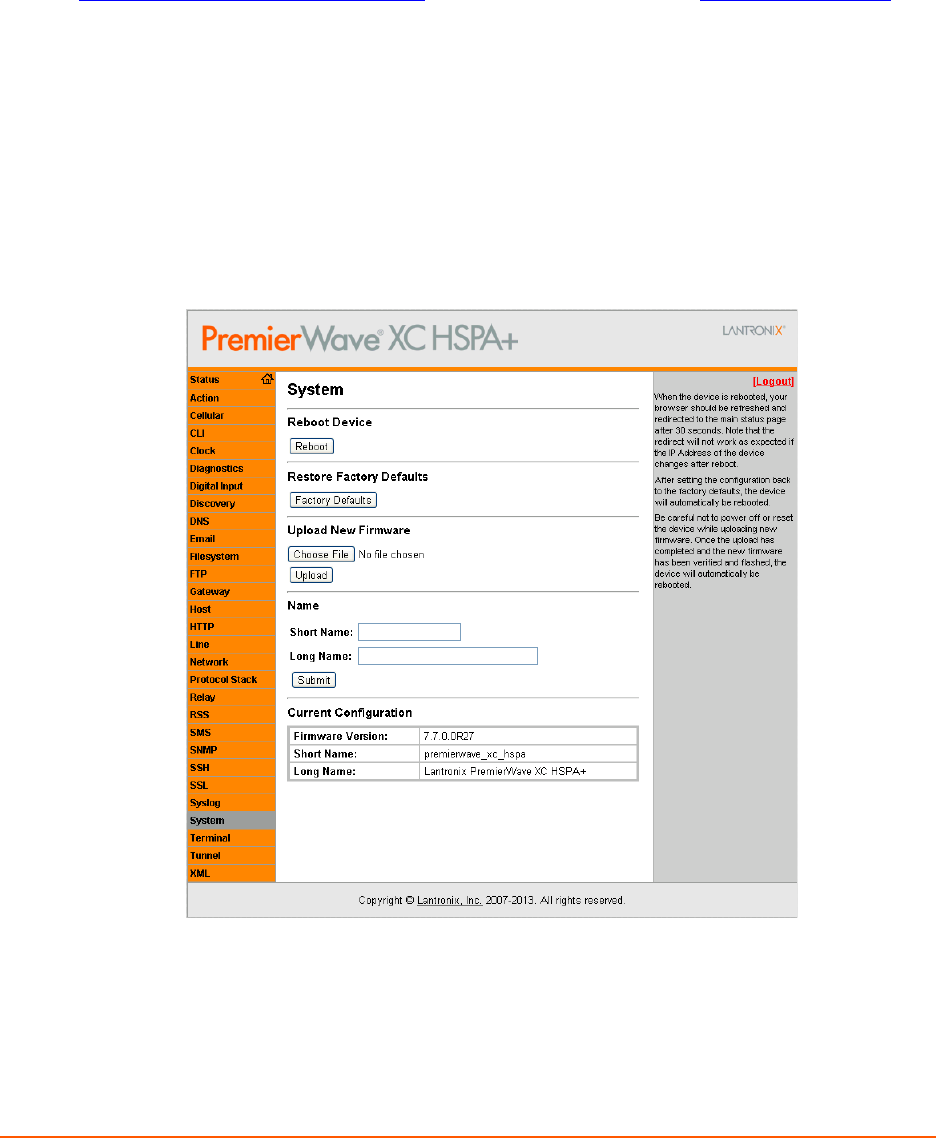
PremierWave XC HSPA+ User Guide 94
16: Updating Firmware
Obtaining Firmware
Obtain the most up-to-date firmware and release notes for the unit from the Lantronix Web site
(www.lantronix.com/support/downloads/) or by using anonymous FTP (ftp://ftp.lantronix.com/).
Loading New Firmware through Web Manager
Upload the firmware using the device web manager System page.
To upload new firmware:
1. Select System in the menu bar. The System page appears.
Figure 16-1 Uploading New Firmware
2. Click Browse (under the Upload New Firmware heading) to browse to the firmware file.
3. Select the file and click Open.
4. Click Upload to install the firmware on the PremierWave.
5. Click OK in the confirmation popup which appears. The firmware will be installed and the
PRELIMINARY DRAFT
PRELIMINARY DRAFT

16: Updating Firmware
PremierWave XC HSPA+ User Guide 95
device will automatically reboot afterwards.
6. Close and reopen the web manager internet browser to view the device’s updated web pages.
Note: You may need to increase HTTP Max Bytes in some cases where the browser is
sending data aggressively within TCP windows size limit when file (including firmware
upgrade) is uploaded from webpage.
Loading New Firmware through FTP
Firmware may be updated by sending the file to the PremierWave over an FTP connection. The
destination file name on the PremierWave must be "firmware.rom". The device will reboot upon
successful completion of the firmware upgrade.
Example FTP session:
$ ftp 192.168.10.127
Connected to 192.168.10.127.
220 (vsFTPd 2.0.7)
Name (192.168.10.127:user): admin
331 Please specify the password.
Password:
230 Login successful.
Remote system type is UNIX.
Using binary mode to transfer files.
ftp> put premierwave_xc_7.7.0.0r27.rom
200 PORT command successful. Consider using PASV.
150 Ok to send data.
226 File receive OK.
9308164 bytes sent in 3.05 seconds (3047859 bytes/s)
ftp> quit
221 Goodbye.
PRELIMINARY DRAFT
PRELIMINARY DRAFT

PremierWave XC HSPA+ User Guide 96
17: Branding the PremierWave XC HSPA+
This chapter describes how to brand your PremierWave by using Web Manager and Command
Line Interface (CLI). It contains the following sections on customization:
Web Manager Customization
Short and Long Name Customization
Web Manager Customization
Customize the Web Manager's appearance by modifying index.html, style.css, and the product
logo. The style (fonts, colors, and spacing) of the Web Manager is controlled with style.css. The
text and graphics are controlled with index.html. The product logo is the image in top-left corner of
the page and defaults to a product name image.
Note: The recommended dimensions of the new graphic are 300px width and 50px
height.
The Web Manager files are hidden and are incorporated directly into the firmware image but may
be overridden by placing the appropriate file in the appropriate directory on the PremierWave file
system.
Web Manager files can be retrieved and overridden with the following procedure:
1. FTP to the PremierWave device.
2. Make a directory (mkdir) and name it http/config .
3. Change to the directory (cd) that you created in step 2 (http/config).
4. Save the contents of index.html and style.css by using a web browser and navigating to
http://<PremierWave>/config/index.html and http://<PremierWave>/
config/style.css.
5. Modify the file as required or create a new one with the same name.
6. To customize the product logo, save the image of your choice as
PremierWave_logo.gifand PremierWave.png .
7. Put the file(s) by using put <filename>.
8. Type quit. The overriding files appear in the file system's http/config directory.
9. Restart any open browser to view the changes.
10. If you wish to go back to the default files in the firmware image, simply delete the overriding
files from the file system.
PRELIMINARY DRAFT
PRELIMINARY DRAFT

17: Branding the PremierWave XC HSPA+
PremierWave XC HSPA+ User Guide 97
Short and Long Name Customization
You can customize the short and long names in your PremierWave. The names display in the CLI
show command and in the System web page in the Current Configuration table. The short name is
used for the show command. Both names display in the CLI Product Type field.
Table 17-1 Short and Long Name Settings
To Customize Short or Long Names
Using Web Manager
To access the area with options to customize the short name and the long name of the
product, or to view the current configuration, click System in the menu.
Using the CLI
To enter the command level: enable
Using XML
Include in your file:
<configitem name=“short name”>
and
<configitem name=“long name”>
Name Settings Description
Short Name Enter a short name for the system name. A maximum of 32 characters are allowed.
Long Name Enter a long name for the system name. A maximum of 64 characters are allowed.
PRELIMINARY DRAFT
PRELIMINARY DRAFT

PremierWave XC HSPA+ User Guide 98
Appendix A: Technical Specifications
Network
Cellular
UMTS/HSPA+ (850/800/900/1900/2100 MHz)
GSM/GPRS/EDGE (850/900/1800/1900 MHz)
Transfer Rates - up to 14.4 Mbps (downlink), up to
7.2Mbps (uplink)
1 Secure SIM Slot
2 x Omni-Directional Penta-band Antennas
Ethernet
10BaseT and 100Base-TX Link (auto sending full and
half duplex support)
RJ-45 Connector with LEDs (operation and activity)
1.5 KV Isolation
Serial Interface
Software selectable RS-232/422/485
Software selectable RS-485 termination
Serial data rates from 300 to 921 Kbps
Characters: 7 or 8 data bits
Parity: Odd, Even, None
Stop Bits: 1 or 2
Modem Control: DTR, DSR/DCD
Flow Control: XON/XOFF (SW), CTS/RTS (HW)
Serial Connector
2 x DB9M (DTE) with 15KV ESD protection per port
USB Interface
USB Mass Storage Device Support
PRELIMINARY DRAFT
PRELIMINARY DRAFT

PremierWave XC HSPA+ User Guide 99
USB Connector
1 x USB Type A Host Connector (USB 2.0)
I/O Interface
Input
Connection: Sensors/Events
Voltage acceptance: 0 to 30 VDC
Digital input event: User configurable
Optical: 1.5 KV
Output
Software: Turn Relay Output ON and OFF
Automatic Event Trigger: ON or OFF (possible events include loss of cellular link, loss of
Ethernet link, digital input event)
Relay Output Response: User configurable
Support 1A @24V
I/O Connectors
2 x Digital Input, 1 x Relay Output (Terminal Block)
LED Indicators
Cellular Mode, Signal Strength, Serial RX/TX, USB
Connection, System Status, Power, Ethernet Speed,
Ethernet Activity
Security
SSL v3, SSH v2, Client & Server, Supports up to
2048-bit certificates
Encryption: AES, 3DES, RC4
Authentication: SHA-1, MDS, Base-64 User Access Lists
PRELIMINARY DRAFT
PRELIMINARY DRAFT

PremierWave XC HSPA+ User Guide 100
Management
Web Browser (SSL option for secure login)
CLI (over serial ports, Telnet, or SSH)
XML Configuration Records via CLI or FTP
Supports SNMP version 2c
Software
Lantronix Device Server Application Suite
DeviceInstaller.
Power
Input Voltage: 9-30 VDC
Power Consumption: 3.6 Watts (typical)
Power Supply (100 - 240 VAC, 50-60 Hz, 12 VDC @ 1.8A) with locking barrel connector and
regional adapters, -40° to +75°C
Environmental
Operating Temperature: -40° to +70°C
Storage Temperature : -40° to +85°C
Relative Humidity: 5% to 95% non-condensing
IP Rating: 30
Agency Approvals / Compliance
EMC - FCC Part 15 Class B, IC, CE, EN55022, EN55024 Class B
RF - FCC Part 22H, Part 24E, RSS 132,133, EN301-489-1, EN301 489-7, EN301 489-24,
EN301 511, AS/ACIF 2042.1, 2042.3
Safety - UL 60950-1, cUL 60950-1, IEC 60950-1, CSA C22.2 No.60950-1-07, AS/NZS
60950:2000
Network - PTCRB, R&TTE, Carrier Approvals
RoHS, REACH
PRELIMINARY DRAFT
PRELIMINARY DRAFT

PremierWave XC HSPA+ User Guide 101
Dimensions
Size: 9.4 cm (3.7 in) L x 10.9 cm (4.3 in) W x 3.0 cm (1.2 in) H
Weight: 0.44 kg (1.0 lb)
Warranty
5-Year Limited
PRELIMINARY DRAFT
PRELIMINARY DRAFT

PremierWave XC HSPA+ User Guide 102
Appendix B: Compliance
(According to ISO/IEC Guide 17050-1, 17050-2 and EN 45014)
Manufacturer's Name & Address:
Lantronix, Inc.
167 Technology Drive, Irvine, CA 92618 USA
Product Name Model:
PremierWave XC HSPA+
This device complies with part 15 of the FCC Rules. Operation is subject to the following two
conditions: (1) This device may not cause harmful interference, and (2) this device must accept
any interference received, including interference that may cause undesired operation.
This device complies with Industry Canada license-exempt RSS standard(s). Operation is subject
to the following two conditions: (1) this device may not cause interference, and (2) this device must
accept any interference, including interference that may cause undesired operation of the device.
Note: Under Industry Canada regulations, this radio transmitter may only operate using
an antenna of a type and maximum (or lesser) gain approved for the transmitter by
Industry Canada. To reduce potential radio interference to other users, the antenna type
and its gain should be so chosen that the equivalent isotropically radiated power (e.i.r.p.)
is not more than that necessary for successful communication.
This radio transmitter (PremierWave XC HSPA+, 3867A-PWXCHSPA) has been approved by
Industry Canada to operate with the antenna types listed below with the maximum permissible
gain and required antenna impedance for each antenna type indicated. Antenna types not
included in this list, having a gain greater than the maximum gain indicated for that type, are strictly
prohibited for use with this device.
Approved Antenna. Taoglas, TG.09.113, Hinged Monopole, 2.8dBi peak gain.
Cet appareil conforme aux normes exempts de licence CNR d'Industrie Canada. Son
fonctionnement est soumis aux deux conditions suivantes: (1) cet appareil ne doit pas provoquer
d'interférences, et (2) cet appareil doit accepter toute interférence, y compris les interférences
pouvant provoquer un fonctionnement indésirable de l'appareil.
Note: En vertu de la réglementation d' Industrie Canada, cet émetteur de radio ne peut
fonctionner à l'aide d'une antenne d'un type et un maximum (ou moins) gain approuvé
pour l'émetteur par Industrie Canada. Pour réduire risque d'interférence aux autres
utilisateurs, le type d'antenne et son gain doivent être choisis afin que la puissance
isotrope rayonnée équivalente (PIRE) ne dépasse pas ce qui est nécessaire pour une
communication réussie.
Cet émetteur radio (PremierWave XC HSPA +, 3867A-PWXCHSPA) a été approuvé par Industrie
Canada pour fonctionner avec les types d'antennes énumérés ci-dessous avec le gain maximal
admissible et impédance d'antenne requise pour chaque type d'antenne indiqué. Types
d'antennes pas inclus dans cette liste, ayant un gain supérieur au gain maximal indiqué pour ce
type, sont strictement interdits pour une utilisation avec cet appareil.
Approuvé antenne. Taoglas, TG.09.113, Monopole charnière, un gain maximal 2.8dBi
PRELIMINARY DRAFT
PRELIMINARY DRAFT

Appendix B: Compliance
PremierWave XC HSPA+ User Guide 103
Conforms to the following standards or other normative documents:
Emissions
FCC 15.107:2013
FCC 15.109:2013
FCC 22H:2011
FCC 24E:2011
RSS-132:2005
RSS-133:2009
EN 301 489-24
EN 301 489-7
EN 301 511 (GSM & EDGE)
EN 301 908-1
EN 301 908-2 (W-CDMA & HSDPA)
EN 62311
Immunity
EN 61000-4-2:2009
EN 61000-4-3:2006 + A1: 2008
EN 61000-4-4:2004 + A1: 2010
EN 61000-4-5:2006
EN 61000-4-6:2009
EN 61000-4-8:2010
EN 61000-4-11:2004
Safety
Low Voltage Directive (2006/95/EC)
EN 60950-1:2006+A11+A1+A12 which includes all European national differences
IEC 60950-1:2005+A1
UL 60950-1, 2nd Edition, 2011-12-19
(Information Technology Equipment - Safety - Part 1: General Requirements)
CSA C22.2 No. 60950-1-07, 2nd Edition, 2011-12
(Information Technology Equipment - Safety - Part 1: General Requirements)I
VCCI
C-TICK
PRELIMINARY DRAFT
PRELIMINARY DRAFT

Appendix B: Compliance
PremierWave XC HSPA+ User Guide 104
Manufacturer's Contact:
Lantronix, Inc.
167 Technology Drive, Irvine, CA 92618 USA
Tel: 949-453-3990
Fax: 949-450-7249
RoHS Notice
All Lantronix products in the following families are China RoHS-compliant and free of the following hazardous
substances and elements:
O: toxic or hazardous substance contained in all of the homogeneous materials for this part is below the limit
requirement in SJ/T11363-2006.
X: toxic or hazardous substance contained in at least one of the homogeneous materials used for this part is above the
limit requirement in SJ/T11363-2006.
Lead (Pb) Mercury (Hg) Polybrominated biphenyls (PBB)
Cadmium (Cd) Hexavalent Chromium (Cr (VI)) Polybrominated diphenyl ethers (PBDE)
Product Family Name Toxic or hazardous Substances and Elements
Lead
(Pb) Mercury
(Hg) Cadmium
(Cd) Hexavalent
Chromium (Cr
(VI))
Polybrominate
d biphenyls
(PBB)
Polybrominated
diphenyl ethers (PBDE)
DSC 0 0 0 0 0 0
EDS 0 0 0 0 0 0
IntelliBox 0 0 0 0 0 0
MatchPort 0 0 0 0 0 0
Micro 0 0 0 0 0 0
MSS100 0 0 0 0 0 0
PremierWave 0 0 0 0 0 0
SCS 0 0 0 0 0 0
SecureBox 0 0 0 0 0 0
SLB 0 0 0 0 0 0
SLC 0 0 0 0 0 0
SLP 0 0 0 0 0 0
Spider and Spider Duo 0 0 0 0 0 0
UBox 0 0 0 0 0 0
UDS1100 and 2100 0 0 0 0 0 0
WiBox 0 0 0 0 0 0
WiPort 0 0 0 0 0 0
xDirect 0 0 0 0 0 0
xPico 0 0 0 0 0 0
XPort 0 0 0 0 0 0
XPress DR & XPress-DR+ 0 0 0 0 0 0
xPrintServer 0 0 0 0 0 0
xSenso 0 0 0 0 0 0
PRELIMINARY DRAFT
PRELIMINARY DRAFT

PremierWave XC HSPA+ User Guide 105
Appendix C: Technical Support
If you are unable to resolve an issue using the information in this documentation, please contact
Technical Support:
Technical Support US
Check our online knowledge base or send a question to Technical Support at
http://www.lantronix.com/support.
Technical Support Europe, Middle East, Africa
Phone: +33 13 930 4172
Email: eu_techsupp@lantronix.com or eu_support@lantronix.com
Firmware downloads, FAQs, and the most up-to-date documentation are available at
http://www.lantronix.com/support
When you report a problem, please provide the following information:
Your name, and your company name, address, and phone number
Lantronix model number
Lantronix serial number/MAC address
Firmware version (on the first screen shown when you Telnet to the device and type show)
Description of the problem
Status of the unit when the problem occurred (please try to include information on user and
network activity at the time of the problem)
Additionally, it may be useful to export and submit the exported XML Configuration file.
PRELIMINARY DRAFT
PRELIMINARY DRAFT

PremierWave XC HSPA+ User Guide 106
Appendix D: Binary to Hexadecimal Conversions
Many of the unit's configuration procedures require you to assemble a series of options
(represented as bits) into a complete command (represented as a byte).
The resulting binary value must be converted to a hexadecimal representation.
Use this chapter to learn to convert binary values to hexadecimals or to look up hexadecimal
values in the tables of configuration options. The tables include:
Command Mode (serial string sign-on message)
AES Keys
Converting Binary to Hexadecimal
Following are two simple ways to convert binary
numbers to hexadecimal notation.
Conversion Table
Hexadecimal digits have values ranging from 0 to F,
which are represented as 0-9, A (for 10), B (for 11),
etc. To convert a binary value (for example, 0100
1100) to a hexadecimal representation, treat the
upper and lower four bits separately to produce a two-
digit hexadecimal number (in this case, 4C). Use the
following table to convert values from binary to
hexadecimal.
Scientific Calculator
Another simple way to convert binary to hexadecimal
is to use a scientific calculator, such as the one
available on the Windows operating systems. For
example:
1. On the Windows Start menu, click Programs ->
Accessories -> Calculator.
2. On the View menu, select Scientific. The
scientific calculator appears.
3. Click Bin (Binary), and type the number you want
to convert.
Decimal Binary Hex
0 0000 0
1 0001 1
2 0010 2
3 0011 3
4 0100 4
5 0101 5
6 0110 6
7 0111 7
8 1000 8
9 1001 9
10 1010 A
11 1011 B
12 1100 C
13 1101 D
14 1110 E
15 1111 F
Table D-1 Binary to Hexadecimal
Conversion
PRELIMINARY DRAFT
PRELIMINARY DRAFT

PremierWave XC HSPA+ User Guide 107
Figure D-2 Windows Scientific Calculator
4. Click Hex. The hexadecimal value appears.
Figure D-3 Hexadecimal Values in the Scientific Calculator
PRELIMINARY DRAFT
PRELIMINARY DRAFT

PremierWave XC HSPA+ User Guide 108
Appendix E: USB-CDC-ACM Device Driver File
for Windows Hosts
The following file may be used to enable Windows to recognize the USB-CDC-ACM connection to
the PremierWave's USB Device port.
Create the linux-cdc-acm.inf file on the Windows host somewhere using the contents provided
below. When Windows prompts for a device driver for the USB connection, point it to this file.
Note: For Windows 7 installation, it is recommended to manually install the driver before
plugging in the USB cable to the PremierWave device port. This can be done by installing
a legacy driver for a COM port, with the Have Disk... option.
; Windows USB CDC ACM Setup File
; Based on INF template which was:
; Copyright (c) 2000 Microsoft Corporation
; Copyright (c) 2007 Microchip Technology Inc.
; likely to be covered by the MLPL as found at:
; <http://msdn.microsoft.com/en-us/cc300389.aspx#MLPL>.
; For use only on Windows operating systems.
[Version]
Signature="$Windows NT$"
Class=Ports
ClassGuid={4D36E978-E325-11CE-BFC1-08002BE10318}
Provider=%Linux%
DriverVer=11/15/2007,5.1.2600.0
[Manufacturer]
%Linux%=DeviceList, NTamd64
[DestinationDirs]
DefaultDestDir=12
;-----------------------------------------------------------------------
; Windows 2000/XP/Vista-32bit Sections
;-----------------------------------------------------------------------
[DriverInstall.nt]
include=mdmcpq.inf
CopyFiles=DriverCopyFiles.nt
AddReg=DriverInstall.nt.AddReg
[DriverCopyFiles.nt]
usbser.sys,,,0x20
[DriverInstall.nt.AddReg]
HKR,,DevLoader,,*ntkern
HKR,,NTMPDriver,,USBSER.sys
HKR,,EnumPropPages32,,"MsPorts.dll,SerialPortPropPageProvider"
[DriverInstall.nt.Services]
AddService=usbser, 0x00000002, DriverService.nt
[DriverService.nt]
DisplayName=%SERVICE%
ServiceType=1
StartType=3
ErrorControl=1
ServiceBinary=%12%\USBSER.sys
PRELIMINARY DRAFT
PRELIMINARY DRAFT

Appendix E: USB-CDC-ACM Device Driver File for Windows Hosts
PremierWave XC HSPA+ User Guide 109
;-----------------------------------------------------------------------
; Vista-64bit Sections
;-----------------------------------------------------------------------
[DriverInstall.NTamd64]
include=mdmcpq.inf
CopyFiles=DriverCopyFiles.NTamd64
AddReg=DriverInstall.NTamd64.AddReg
[DriverCopyFiles.NTamd64]
USBSER.sys,,,0x20
[DriverInstall.NTamd64.AddReg]
HKR,,DevLoader,,*ntkern
HKR,,NTMPDriver,,USBSER.sys
HKR,,EnumPropPages32,,"MsPorts.dll,SerialPortPropPageProvider"
[DriverInstall.NTamd64.Services]
AddService=usbser, 0x00000002, DriverService.NTamd64
[DriverService.NTamd64]
DisplayName=%SERVICE%
ServiceType=1
StartType=3
ErrorControl=1
ServiceBinary=%12%\USBSER.sys
;-----------------------------------------------------------------------
; Vendor and Product ID Definitions
;-----------------------------------------------------------------------
; When developing your USB device, the VID and PID used in the PC side
; application program and the firmware on the microcontroller must match.
; Modify the below line to use your VID and PID. Use the format as shown
; below.
; Note: One INF file can be used for multiple devices with different
; VID and PIDs. For each supported device, append
; ",USB\VID_xxxx&PID_yyyy" to the end of the line.
;-----------------------------------------------------------------------
[SourceDisksFiles]
[SourceDisksNames]
[DeviceList]
%DESCRIPTION%=DriverInstall, USB\VID_0525&PID_A4A7,
USB\VID_0525&PID_A4AB&MI_02
[DeviceList.NTamd64]
%DESCRIPTION%=DriverInstall, USB\VID_0525&PID_A4A7,
USB\VID_0525&PID_A4AB&MI_02
;-----------------------------------------------------------------------
; String Definitions
;-----------------------------------------------------------------------
;Modify these strings to customize your device
;-----------------------------------------------------------------------
[Strings]
Linux = "Linux Developer Community"
DESCRIPTION = "Gadget Serial"
SERVICE = "USB RS-232 Emulation Driver"
PRELIMINARY DRAFT
PRELIMINARY DRAFT