lantronix WIBATT Wireless Device Server User Manual Users Guide WiPort
lantronix Wireless Device Server Users Guide WiPort
Contents
- 1. User Manual Data Link Connection
- 2. User Manual Wiport
User Manual Wiport

WiPort™ User Guide
Part Number 900-332
Revision F November 2005

WiPort™ User Guide 2
Copyright and Trademark
© 2005, Lantronix. All rights reserved. No part of the contents of this book may be
transmitted or reproduced in any form or by any means without the written permission
of Lantronix. Printed in the United States of America.
WiPort, with its patent-pending technology, is a trademark of Lantronix.
Ethernet is a trademark of XEROX Corporation. UNIX is a registered trademark of
The Open Group. Windows 95, Windows 98, Windows 2000, Windows NT, and
Windows XP are trademarks of Microsoft Corp. Netscape is a trademark of Netscape
Communications Corporation.
Contacts
Lantronix Corporate Headquarters
15353 Barranca Parkway
Irvine, CA 92618, USA
Phone: 949-453-3990
Fax: 949-453-3995
Technical Support
Phone: 800-422-7044 or 949-453-7198
Fax: 949-450-7226
Online: www.lantronix.com/support
Email support@lantronix.com
Sales Offices
For a current list of our domestic and international sales offices, go to the Lantronix
web site at http://www.lantronix.com/about/contact/

WiPort™ User Guide 3
Disclaimer and Revisions
This equipment has been tested and found to comply with the limits for a Class B
digital device, pursuant to Part 15 of the FCC Rules. These limits are designed to
provide reasonable protection against harmful interference in a residential
installation. This equipment generates, uses, and can radiate radio frequency energy
and, if not installed and used in accordance with the instructions, may cause harmful
interference to radio communications. However, there is no guarantee that
interference will not occur in a particular installation. If this equipment does cause
harmful interference to radio or television reception, which can be determined by
turning the equipment off and on, the user is encouraged to try to correct the
interference by one of the following measures:
Reorient or relocate the receiving antenna.
Increase the separation between the equipment and receiver.
Connect the equipment into an outlet on a circuit different from that to which
the receiver is connected.
Consult the dealer or an experienced radio/TV technician for help.
This device complies with Part 15 of the FCC Rules. Operation is subject to the
following two conditions: (1) This device may not cause harmful interference, and (2)
this device must accept any interference received, including interference that may
cause undesired operation.
This device is intended only for OEM Integrators of Mobile Equipment. The OEM
integrators should be aware of the following important issues.
Labeling of the End Product
The end product to integrate this module has to be clearly identified on the label that
this end product contains an FCC approved RF module. The format of such
statement could be "Contains Transmitter with FCC ID: R68WIPORT" or similar.
Integration Note
a) This module is authorized under limited module approval specified to mobile host
equipment. So, the antenna must be installed such that a minimum of 20cm is
maintained between the antenna and users.
b) The transmitter module may not be co-located with any other transmitter or
antenna.
As long as the 2 conditions above are met, further transmitter testing will not be
required. However, the OEM integrator is still responsible for testing their end-product
for any additional compliance requirements required with this module installed (for
example, digital device emission, PC peripheral requirements, etc.)
Note 2: In the event that these conditions can not be met (for example
certain laptop configurations, general purpose PCMCIA or similar cards, or
co-location with another transmitter), then the FCC authorization is no longer
considered valid and the FCC ID can not be used on the final product
(including the transmitter) and obtaining a separate FCC authorization.
Note 3: Changes or modifications to this device not explicitly approved
by Lantronix will void the user's authority to operate this device.

WiPort™ User Guide 4
Contents
Copyright and Trademark _________________________________________________2
Contacts ______________________________________________________________2
Disclaimer and Revisions _________________________________________________3
1: Using This Guide 8
Purpose and Audience ___________________________________________________8
Chapter Summary _______________________________________________________8
Additional Documentation _________________________________________________9
2: Introduction 10
Capabilities ___________________________________________________________10
Applications ___________________________________________________________10
Protocol Support _______________________________________________________11
Configuration Methods __________________________________________________11
Addresses and Port Numbers _____________________________________________11
Hardware Address __________________________________________________________11
IP Address_________________________________________________________________12
Port Numbers ______________________________________________________________12
3: Using DeviceInstaller 13
Accessing WiPort using DeviceInstaller _____________________________________13
Viewing the WiPort’s Current Configuration __________________________________13
4: Configuration Using Web-Manager 16
Accessing WiPort Web-Manager using DeviceInstaller__________________________16
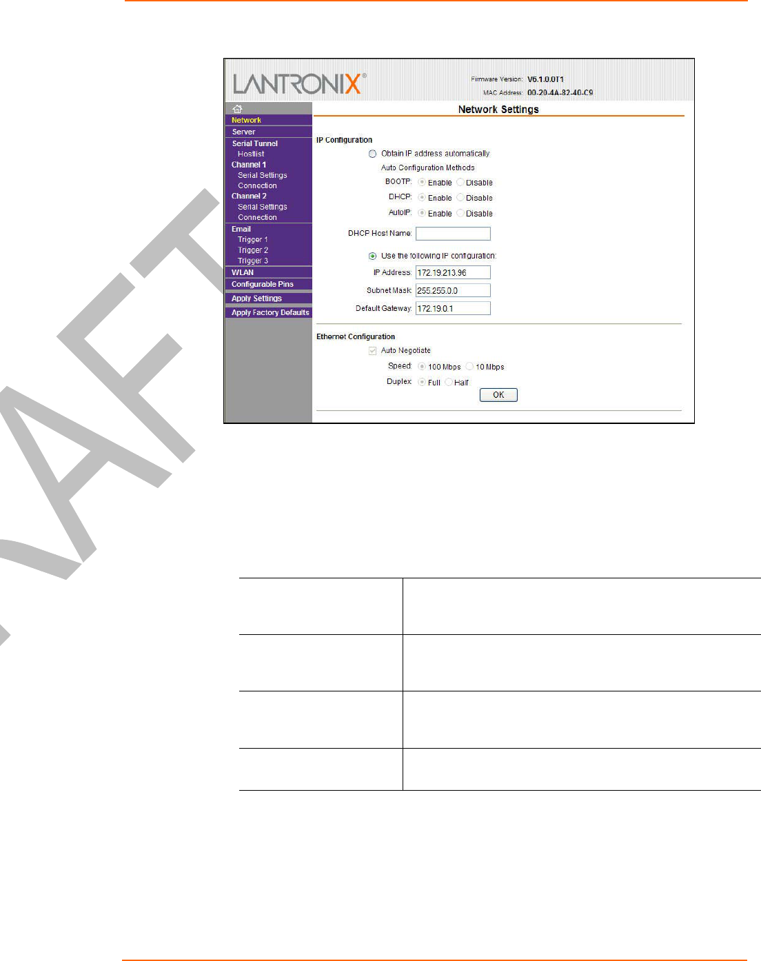
Network Configuration___________________________________________________17
Automatic IP Address Configuration _____________________________________________18
Static IP Address Configuration ________________________________________________19
Server Configuration ____________________________________________________19
Host List Configuration __________________________________________________20
Channel 1 and Channel 2 Configuration _____________________________________21
Serial Settings ______________________________________________________________21
Connection Settings - TCP ____________________________________________________23
Connection Settings - UDP ____________________________________________________26
Email Configuration _____________________________________________________27
Trigger Configuration ________________________________________________________28
WLAN Configuration ____________________________________________________29
Configurable Pin Settings ________________________________________________32
Updating Settings ______________________________________________________34
Applying Factory Default Settings? _________________________________________34
5: Configuration via Serial Mode or Telnet Port 35
Accessing Setup Mode __________________________________________________35
Telnet Access ______________________________________________________________35
Serial Port Access___________________________________________________________36

Contents
WiPort™ User Guide 5
Server Configuration ____________________________________________________37
Set the IP Address __________________________________________________________37
Set the Gateway IP Address___________________________________________________37
Set the Netmask ____________________________________________________________37
Change Telnet Configuration Password __________________________________________38
DHCP Name _______________________________________________________________38
Channel 1 and Channel 2 Configuration _____________________________________39
Baudrate __________________________________________________________________39
I/F (Interface) Mode _________________________________________________________39
Flow______________________________________________________________________40
Port Number _______________________________________________________________41
Connect Mode______________________________________________________________42
Send the Escape Sequence (+++) in Modem Mode_________________________________48
Auto Increment Source Port ___________________________________________________48
Remote IP Address__________________________________________________________48
Remote Port _______________________________________________________________49
DisConnMode ______________________________________________________________49
Flush Mode ________________________________________________________________50
DisConnTime (Inactivity Timeout)_______________________________________________51
SendChar 1 and SendChar2___________________________________________________51
Telnet Terminal Type ________________________________________________________53
Channel (Port) Password _____________________________________________________53
Email Configuration _____________________________________________________53
Mail Server ________________________________________________________________54
Unit Name _________________________________________________________________54
Domain Name ______________________________________________________________54
Recipient 1 ________________________________________________________________54
Recipient 2 ________________________________________________________________54
Trigger 1 __________________________________________________________________54
Trigger 2 __________________________________________________________________55
Trigger 3 __________________________________________________________________55
WLAN Settings ________________________________________________________55
Enable WLAN ______________________________________________________________55
Topology __________________________________________________________________55
Network Name (SSID) _______________________________________________________55
Adhoc Network Channel ______________________________________________________56
Security ___________________________________________________________________56
WEP _____________________________________________________________________56
WPA _____________________________________________________________________56
Fixed or Automatic Data Rate__________________________________________________57
Transmission Data Rate ______________________________________________________57
Enable Power Management ___________________________________________________57
Transmission Power Level ____________________________________________________58
Expert Settings ________________________________________________________58
TCP Keepalive Time _________________________________________________________58
ARP Cache Timeout _________________________________________________________58
Enable High Performance_____________________________________________________58
HTTP Port Number __________________________________________________________59

Contents
WiPort™ User Guide 6
SMTP Port Number__________________________________________________________59
MTU Size _________________________________________________________________59
Alternate MAC Address ______________________________________________________59
Ethernet Connection Type ____________________________________________________59
Security Settings _______________________________________________________59
Disable SNMP______________________________________________________________60
SNMP Community Name _____________________________________________________60
Disable Telnet Setup_________________________________________________________60
Disable TFTP Firmware Upgrade _______________________________________________60
Disable Port 77FE (Hex) ______________________________________________________60
Disable Web Server _________________________________________________________60
Disable Web Setup __________________________________________________________60
Disable ECHO Ports _________________________________________________________60
Enable Encryption___________________________________________________________61
Enable Enhanced Password___________________________________________________61
Disable Port 77F0 (Hex) ______________________________________________________61
Default Settings ________________________________________________________61
Channel 1 Configuration ______________________________________________________61
Channel 2 Configuration ______________________________________________________62
WLAN Settings _____________________________________________________________62
*On select models only _____________________________________________________________62
Expert Settings _____________________________________________________________62
Security Settings ____________________________________________________________63
*On select models only _____________________________________________________________63
Email Settings ______________________________________________________________63
Exit Configuration Mode _________________________________________________63
6: Configurable Pins 64
Defaults Settings: ___________________________________________________________64
Features: __________________________________________________________________64
Control Protocol________________________________________________________64
Guidelines _________________________________________________________________64
Commands ________________________________________________________________65
Examples_____________________________________________________________67
7: Monitor Mode 69
Entering Monitor Mode via the Serial Port____________________________________69
Entering Monitor Mode via the Network Port__________________________________69
Monitor Mode Commands ________________________________________________69
8: Updating Firmware 71
Obtaining Firmware _____________________________________________________71
Reloading Firmware ____________________________________________________71
Using TFTP: Graphical User Interface ___________________________________________71
Using TFTP: Command Line Interface ___________________________________________72
Recovering the Firmware Using the Serial Port ____________________________________72
9: Troubleshooting 73
Diagnostic LED States___________________________________________________73
Problems and Error Messages ____________________________________________74

Contents
WiPort™ User Guide 7
Technical Support ______________________________________________________77

WiPort™ User Guide 8
1
1:
:
U
Us
si
in
ng
g
T
Th
hi
is
s
G
Gu
ui
id
de
e
Purpose and Audience
This guide provides the information needed to configure, use and update the
WiPortTM and is intended for software developers and system integrators who are
embedding the WiPort in their designs. This User Guide covers WiPort Device
Server versions WP2001000-01, WP2002000-01, WP2004000-01 (WiPort-485), and
WP2001000G-02 (WiPort-G).
Note: For the WiPort model WP2001000M-02, additional information can be found in
the Modbus Protocol User Guide located at
www.lantronix.com/support/documentation.html .
Chapter Summary
The remaining chapters in this guide include:
Introduction Describes the main features of the WiPort and the protocols it
supports.
Using DeviceInstaller Provides information for viewing the WiPort’s configuration using
DeviceInstaller.
Configuration Using Web-
Manager Details configuration using the Web-Manager to set parameters
such as port and server properties.
Configuration via Serial Mode or
Telnet Port Provides instructions for accessing Setup Mode (command line
interface) using a Telnet connection through the network or a
terminal or terminal emulation program through the serial port.
Details the parameters that you must configure.
Configurable Pins Provides instructions for configuring the eleven General Purpose
I/O pins.
Monitor Mode Provides instructions for accessing and using the command line
interface for monitoring the network and diagnosing problems.
Updating Firmware Provides instructions for obtaining the latest firmware and updating
the WiPort.
Troubleshooting Describes common problems and error messages and how to
contact Lantronix Technical Support. Also provides information on
diagnostic LEDs.

Using This Guide
WiPort™ User Guide 9
Additional Documentation
The following guides are available on the product CD and the Lantronix web site
(www.lantronix.com)
WiPort Development Kit Quick
Start Guide Briefly explains the basics to get the WiPort up
and running.
WiPort Integration Guide Provides information about the WiPort
hardware and integrating the WiPort into
another product.

WiPort™ User Guide 10
2
2:
:
I
In
nt
tr
ro
od
du
uc
ct
ti
io
on
n
WiPort is a wireless embedded device server that provides a network-enabling
solution based on the IEEE 802.11b wireless standard. WiPort allows Original
Equipment Manufacturers (OEMs) to add wireless connectivity to their products by
incorporating it onto a circuit board.
The WiPort functions independently of a PC, providing a fully integrated solution that
combines a processor, memory, 802.11b, 802.11g transceiver, and dual high-speed
serial ports into a single compact module. It includes an operating system, an
embedded Web server, and a full TCP/IP protocol stack. In addition, the WiPort
sends email alerts and supports numerous other network communication protocols,
including ARP, UDP, TCP, ICMP, Telnet, AutoIP, DHCP, HTTP, SNMP, and SMTP.
Both Wired Equivalent Privacy (WEP) and Wireless Protected Access (WPA) are
available for security. WEP uses an RC4 encryption algorithm with a 64-bit or 128-bit
key. This key jumbles the data before it is sent over the airwaves. WPA is more
secure because re-keying is required. With WPA, the re-keying of global encryption
keys is required. This key is changed using TKIP for unicast traffic.
For OEMs who wish to customize the user interface by employing common and
familiar tools, the WiPort serves applets to a Web browser, resulting in interactive
Web pages. This customization of HTML Web pages and configuration screens
tailors the WiPort to fit unique requirements.
Capabilities
The WiPort device server has the following capabilities:
Communication between TCP and UDP to serial.
Wireless interface (802.11b and 802.11g) with WEP or WPA protection.
Ethernet interface.
Email notification of configurable alarms and events.
Upgradeable firmware.
SNMP monitoring.
Connects devices through a TCP or UDP data channel to computers or to
another device server.
Contains a web server allowing presentation of custom content and easy
configuration through the browser.
Contains eleven programmable I/O pins used to monitor or control attached
devices.
Applications
The WiPort device server connects serial devices such as those listed below to
wireless and Ethernet networks using the IP protocol family.

Introduction
WiPort™ User Guide 11
Remote sensing
CNC controllers
Data collection devices
Telecommunications equipment
Data display devices
Security alarms and access control devices
Time clocks and terminals
Protocol Support
The WiPort device server uses the TCP/IP protocol stack for network
communications. Other supported protocols include:
ARP, UDP, TCP, ICMP, Telnet, TFTP, AutoIP, DHCP, HTTP, and SNMP for
network communications and management.
TCP, UDP, and Telnet for connections to the serial port.
TFTP for firmware and web page updates.
IP for addressing, routing, and data block handling over the network.
User Datagram Protocol (UDP) for typical datagram applications in which
devices interact with other devices without maintaining a point-to-point
connection.
SMTP for e-mail transmission.
Configuration Methods
For the unit to operate correctly on a network, it must have a unique IP address on
the network. There are three basic methods for logging into the device server:
DeviceInstaller: View the current WiPort configuration using a Graphical User
Interface (GUI) on a PC attached to a network. (See 3:Using DeviceInstaller.)
Web-Manager: Through a web interface, configure the WiPort and its settings using
the WiPort’s Web-Manager. (See 4:Configuration Using Web-Manager.)
Serial & Telnet Ports: There are two approaches to accessing Serial Mode. Make
a Telnet connection to the network port (9999) or connect a terminal (or a PC running
a terminal emulation program) to the unit’s serial port. (See 5:Configuration via Serial
Mode or Telnet Port.)
Addresses and Port Numbers
Hardware Address
The hardware address is also referred to as the Ethernet address or the MAC
address. The first three bytes of the Ethernet address are fixed and read 00-20-4A,
identifying the unit as a Lantronix product. The fourth, fifth, and sixth bytes are unique
numbers assigned to each unit.
Example: 00-20-4A-14-01-18
Note: Make note of the MAC address. It is needed to locate the WiPort
using DeviceInstaller.

Introduction
WiPort™ User Guide 12
IP Address
Every device connected to an IP network must have a unique IP address. This
address is used to reference the specific unit. The WiPort is automatically assigned
an IP address on DHCP-enabled networks as it is DHCP-enabled by default.
Port Numbers
Every TCP connection and every UDP datagram is defined by a destination IP
address and a port number. For example, a Telnet application commonly uses port
number 23. A port number is similar to an extension on a phone system.
The unit's serial channel (port) can be associated with a specific TCP/UDP port
number. Port number 9999 is reserved for access to the unit's Setup (configuration)
Mode window. Ports 0-1024 are reserved as well. For more information on reserved
port numbers, refer to Table 5-6. Reserved Port Numbers.

WiPort™ User Guide 13
3
3:
:
U
Us
si
in
ng
g
D
De
ev
vi
ic
ce
eI
In
ns
st
ta
al
ll
le
er
r
This chapter covers the steps for viewing the WiPort device server’s properties and
device details.
Accessing WiPort using DeviceInstaller
Note: Make note of the MAC address. It is needed to locate the WiPort
using DeviceInstaller. For more information on the hardware address, see
Hardware Address on page 11.
Follow the instructions on the product CD to install and run DeviceInstaller.
1. Click StartPrograms LantronixDeviceInstallerDeviceInstaller.
2. Click on the Wireless folder. The list of Lantronix wireless devices available
displays.
3. Expand the list of WiPorts by clicking the + symbol next to the WiPort icon. Select
the WiPort unit by clicking on its IP address to view its configuration.
Viewing the WiPort’s Current Configuration
Follow the Accessing WiPort using DeviceInstaller on page 13 to locate the WiPort.
1. In the right window, click the Device Details tab. The current WiPort
configuration displays:
Name Configurable field. Enter a name to identify the WiPort.
Double-click on the field, type in the value, and press Enter to
complete. This name is not visible on other PCs or laptops
using DeviceInstaller.
Group Configurable field. Enter a group to categorize the WiPort.
Double-click on the field, type in the value, and press Enter to
complete. This group name is not visible on other PCs or
laptops using DeviceInstaller.
Comments Configurable field. Enter comments for the WiPort. Double-
click on the field, type in the value, and press Enter to
complete. This description or comment is not visible on other
PCs or laptops using DeviceInstaller.
Device Family Non-configurable field. Displays the WiPort’s device family
type as Wireless.
Type Non-configurable field. Displays the device type as WiPort.
ID Non-configurable field. Displays the WiPort’s ID embedded
within the box.
Hardware Address Non-configurable field. Displays the WiPort’s hardware (or
MAC) address.

Using DeviceInstaller
WiPort™ User Guide 14
Firmware Version Non-configurable field. Displays the firmware currently
installed on the WiPort.
Online Status Non-configurable field. Displays the WiPort’s status as online,
offline, unreachable (the WiPort is on a different subnet), or
busy (the WiPort is currently performing a task).
Telnet Port Non-configurable field. Displays the WiPort’s port for telnet
sessions.
WebPort Non-configurable field. Displays the WiPort’s port for Web-
Manager configuration.
Maximum Baud Rate
Supported Non-configurable field. Displays the WiPort’s maximum baud
rate. Note: the WiPort may not currently be running at this
rate.
Firmware Upgradeable Non-configurable field. Displays True, indicating the WiPort’s
firmware is upgradeable as newer version become available.
IP Address Non-configurable field. Displays the WiPort’s current IP
address. To change the IP address, see 4:Configuration Using
Web-Manager or 5:Configuration via Serial Mode or Telnet
Port.
Subnet Mask Non-configurable field. Displays the WiPort’s current subnet
mask. To change the subnet mask, see 4:Configuration Using
Web-Manager or 5:Configuration via Serial Mode or Telnet
Port.
Gateway Non-configurable field. Displays the WiPort’s current
gateway. To change the gateway, see 4:Configuration Using
Web-Manager or 5:Configuration via Serial Mode or Telnet
Port.
Number of Ports Non-configurable field. Displays the number of ports on the
WiPort.
Configurable Pins
Available Non-configurable field. Displays True, indicating configurable
pins are available on the WiPort.
Email Trigger Available Non-configurable field. Displays True, indicating email
triggers are available on the WiPort.
TCP Keepalive valid
range Non-configurable field. Displays 255, the WiPort’s TCP
keepalive range.
DynamicIP Non-configurable field. Indicates whether the current IP
address on the WiPort was set using static or DHCP.
Number of COB
partitions supported Non-configurable field. Displays the number of COB partitions
supported (between 19 and 59).
Supports AES Data
Stream Non-configurable field. Displays True if the WiPort unit
supports AES encryption.
Support Configurable
Pins Non-configurable field. The WiPort supports configurable
pins.
Supports 485 Non-configurable field. WiPort supports the RS-485 protocol.

Using DeviceInstaller
WiPort™ User Guide 15
Supports 920K Baudrate Non-configurable field. WiPort supports baud rates up to
920K.
Supports Wired Ethernet Non-configurable field. WiPort supports wired Ethernet.
Supports HTTP Setup Non-configurable field. WiPort supports HTTP setup.
Supports 230K Baudrate Non-configurable field. WiPort supports a baud rate of 230K.
Supports Email Triggers Non-configurable field. WiPort supports email triggers.
Supports GPIO
Communication Non-configurable field. WiPort supports communication via
General Purpose Input Output (GPIO).

WiPort™ User Guide 16
4
4:
:
C
Co
on
nf
fi
ig
gu
ur
ra
at
ti
io
on
n
U
Us
si
in
ng
g
W
We
eb
b-
-M
Ma
an
na
ag
ge
er
r
This chapter describes how to configure the WiPort using Web-Manager, Lantronix’s
browser-based configuration tool. The unit’s configuration is stored in nonvolatile
memory and is retained without power. The unit performs a reset after the
configuration is changed and stored.
Accessing WiPort Web-Manager using DeviceInstaller
Note: Make note of the MAC address. It is needed to locate the WiPort
using DeviceInstaller. For more information on the hardware address, see
Hardware Address on page 11.
Follow the instructions on the product CD to install and run DeviceInstaller.
1. Click StartPrograms LantronixDeviceInstallerDeviceInstaller. If the
PC has more than one network adapter, a message displays requesting the
selection of a network adapter. Select an adapter and click OK.
2. Click the Search icon. The list of Lantronix device servers displays in the left
pane.
3. Click on the Wireless folder. The list of Lantronix wireless devices available
displays.
4. Expand the list of WiPorts by clicking the + symbol next to the WiPort icon.
5. Select the WiPort unit by clicking on its IP address.
6. In the right window, click the Web Configuration tab.
7. To view the WiPort’s Web-Manager in the current DeviceInstaller window, click
Go. To open the Web-Manager in a web browser, click Use External Browser.
The Web-Manager displays.

Configuration Using Web-Manager
WiPort™ User Guide 17
Figure 4-1. Web-Manager
The main menu is displayed in the left side of the Web-Manager window.
Note: Alternatively, access the WiPort’s Web-Manager if it is connected to
the network by entering its IP address in a web browser.
Network Configuration
The unit’s network values display upon selecting Network from the main menu. The
following sections describe the configurable parameters within the Network
configuration menu.
Note: The IP address is assigned via DHCP (on DHCP-enabled networks).
Assign a static IP address if preferred.
Configuration Using Web-Manager
WiPort™ User Guide 18
Figure 4-2. Network Settings
Automatic IP Address Configuration
To automatically assign an IP address and its network configuration:
1. Click Network from the main menu.
2. Select Obtain IP address automatically.
3. Enter the following (as necessary):
BOOTP Select Enable to permit the Bootstrap Protocol (BOOTP). The
BOOTP server automatically assigns the IP address from a
pool of addresses.
DHCP Select Enable to permit Dynamic Host Configuration Protocol
(DHCP). DHCP automatically assigns a leased IP address to
the WiPort unit.
Auto-IP The WiPort generates an IP in the 169.254.x.x address range
with a Class B subnet. Select the Disable checkbox to
disable this feature.
DHCP Host Name Enter the name of the host on the network providing the IP
address.
Note: Disabling BOOTP, DHCP, and Auto-IP (i.e. all three checkboxes) is
not advised as the only available IP assignment method will then be ARP or
serial port.
4. Click the OK button when finished.
Configuration Using Web-Manager
WiPort™ User Guide 19
Static IP Address Configuration
To manually assign an IP address and its network configuration:
1. Click Network from the main menu.
2. Select Use the following IP configuration.
3. Enter the following (as necessary):
IP Address If DHCP is not used to assign IP addresses, enter it manually.
The IP address must be set to a unique value in the network.
Subnet Mask A subnet mask defines the number of bits taken from the IP
address that are assigned for the host part.
Default Gateway The gateway address, or router, allows communication to
other LAN segments. The gateway address should be the IP
address of the router connected to the same LAN segment as
the unit. The gateway address must be within the local
network.
4. Click the OK button when finished.
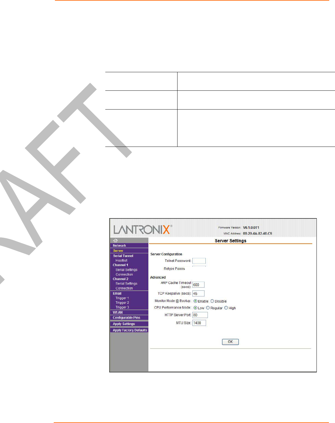
Server Configuration
The unit’s server values display upon selecting Server from the main menu. The
following sections describe the configurable parameters within the Server
configuration menu.
Figure 4-3. Server Settings

Configuration Using Web-Manager
WiPort™ User Guide 20
To configure the WiPort’s device server settings:
1. Click Server from the main menu.
2. Configure or modify the following fields:
Server Configuration
Telnet Password Enter the password required for Telnet access.
Retype Password Re-enter the password required for Telnet access.
Advanced
ARP Cache Timeout When the unit communicates with another device on the
network, it adds an entry into its ARP table. ARP Cache
timeout defines the number of seconds (1-600) before it
refreshes this table.
TCP Keepalive TCP Keepalive time defines how many seconds the unit waits
during an inactive connection before checking its status. If the
unit does not receive a response, it drops that connection.
Enter a value between 0 and 60 seconds. 0 disables
keepalive.
Monitor Mode @ Bootup Select Disable to disable the entry into the monitor mode via
the 'yyy' or 'xx1' key sequence at startup. This command
prevents the unit from entering monitor mode by interpreting
the stream of characters that are received during the device
server's initialization at startup.
CPU Performance Mode Select the WiPort’s performance mode. Higher performance
settings require more energy. Regular is 48 Mhz, High is
88 Mhz. The default is Regular. New screen has only high
and regular.
HTTP Server Port This option allows the configuration of the web server port
number. The valid range is 1-65535. The default HTTP
server port number is 80.
MTU Size The Maximum Transmission Unit (MTU) is the largest physical
packet size a network can transmit for TCP and UDP. Enter
between 512 and 1400 bytes. The default is 1400 bytes.
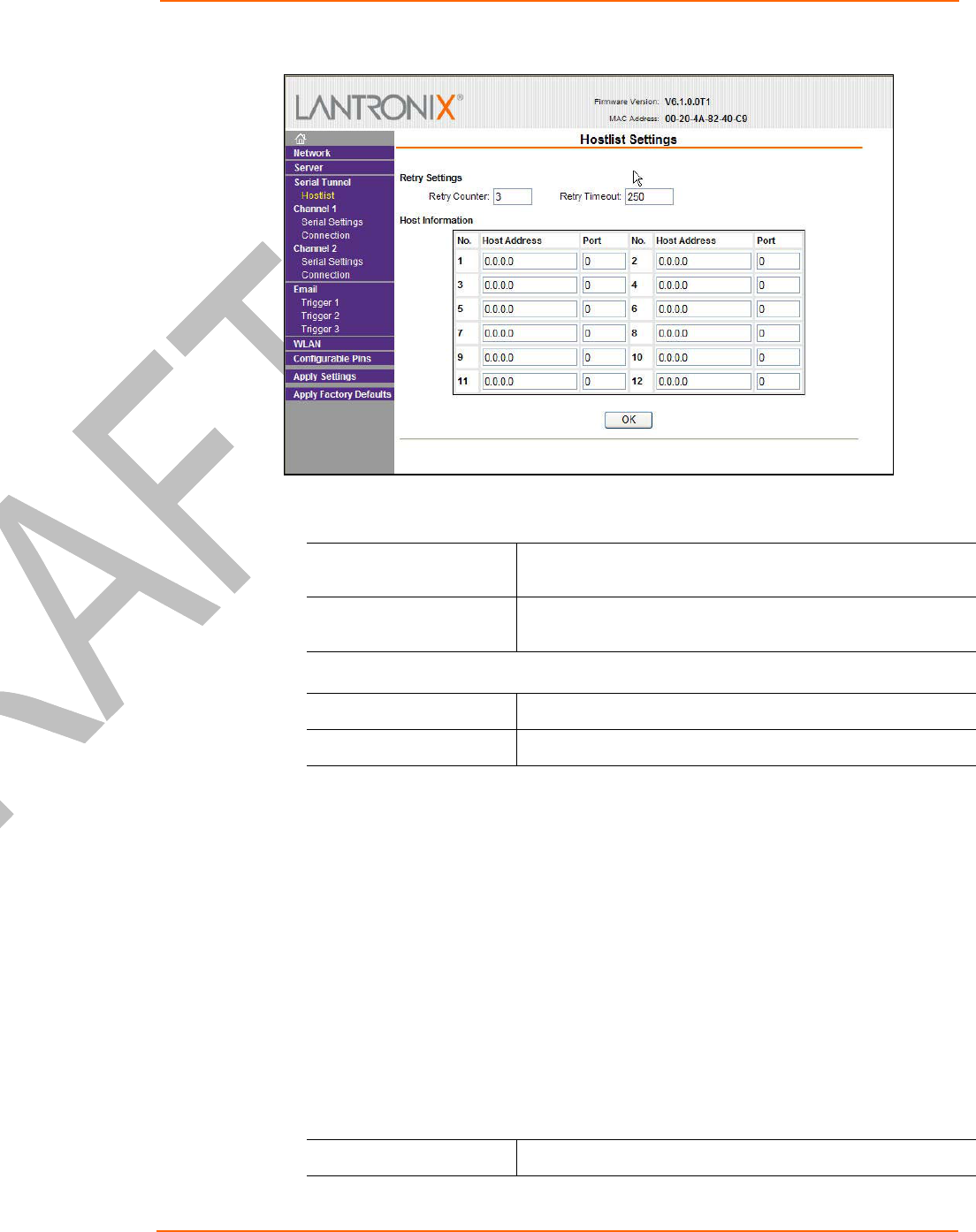
Host List Configuration
The WiPort scrolls through the host list until it connects to a device listed in the host
list table. After a successful connection, the unit stops trying to connect to any others.
If this connection fails, the unit continues to scroll through the table until the next
successful connection.
The host list supports a minimum of 1 and a maximum of 12 entries. Each entry
contains an IP address and a port number.
Note: The host list is disabled for Manual and Modem Mode. The unit will not
accept a data connection from a remote device when the hostlist option is
enabled.
To configure the WiPort’s host list:
1. From the main menu, click the Hostlist tab.
Configuration Using Web-Manager
WiPort™ User Guide 21
Figure 4-4. Hostlist Settings
2. Enter or modify the following fields from the Hostlist Settings window:
Retry Settings
Retry Counter Enter the value for the number of times the WiPort should
attempt to retry connecting to the host list.
Retry Timeout Enter the duration (in seconds) the WiPort should abandon
attempting a connection to the host list.
Host Information
Host Address Enter or modify the host’s IP address.
Port Enter the target port number.
Channel 1 and Channel 2 Configuration
Channel 1 and Channel 2 configurations define how the serial ports respond to
network and serial communication.
Serial Settings
To configure a channel’s serial settings:
1. From the main menu, click Serial Settings for either Channel 1 or Channel 2 to
display the Serial Settings page for the selected channel.
Figure 4-5. Channel Serial Settings
2. In the available fields, enter the following information:
Channel 1
Disable Serial Port Available on Channel 1 settin
g
s onl
y
. When selected
,

Configuration Using Web-Manager
WiPort™ User Guide 22
disables communication through the serial port.
Port Settings
Protocol Select the protocol type from the pull down menu for the
selected channel. RS-422/485 4-wire and RS-485 2-wire
options are available on the WiPort-485 only.
Flow Control Flow control manages data flow between devices in a network
to ensure it is processed efficiently. Too much data arriving
before a device is prepared to manage it causes lost or
retransmitted data.
Baud Rate The unit and attached serial device, such as a modem, must
agree on a speed or baud rate to use for the serial connection.
Valid baud rates are 300, 600, 1200, 2400, 4800, 9600
(default), 19200, 38400, 57600, 115200, 230400, 460800, or
921600.
Data Bits Indicates the number of bits in a transmitted data package.
Parity Checks for the parity bit. The default is None.
Stop Bits The stop bit follows the data and parity bits in serial
communication. It indicates the end of transmission.
Pack Control
Enable Packing Select the checkbox to enable packing on the WiPort.
Two firmware-selectable packing algorithms define how and
when packets are sent to the network. The standard algorithm
is optimized for applications in which the unit is used in a local
environment, allowing for very small delays for single
characters, while keeping the packet count low. The alternate
packing algorithm minimizes the packet count on the network
and is especially useful in applications in a routed Wide Area
Network (WAN). Adjusting parameters in this mode can
economize the network data stream.
Idle Gap Time Select the maximum time for inactivity. The default time is 12
milliseconds.
Match 2 Byte Sequence Use to indicate the end of a series of data to be sent as one
group. The sequence must occur sequentially to indicate to
the WiPort end of the data collection.
Match Bytes Use to indicate the end of a series of data to be sent as one
group. Set this value to 00 if specific functions are not
needed.
Send Frame Only After the detection of the byte sequence, indicates whether to
send the data frame or the entire buffer. Select True to send
only the data frame.
Send Trailing Bytes Select the number of bytes to send after the end-of-sequence
characters.
Flush Input Buffer (Serial to Network)
With Active Connect Select Yes to clear the input buffer with a connection that is
initiated from the device to the network.

Configuration Using Web-Manager
WiPort™ User Guide 23
With Passive Connect Select Yes to clear the input buffer with a connection initiated
from the network to the device.
At Time of Disconnect Select Yes to clear the input buffer when the network
connection to or from the device is disconnected.
Flush Output Buffer (Network to Serial)
With Active Connect Select Yes to clear the output buffer with a connection that is
initiated from the device to the network.
With Passive Connect Select Yes to clear the output buffer with a connection initiated
from the network to the device.
At Time of Disconnect Select Yes to clear the output buffer when the network
connection to or from the device is disconnected.
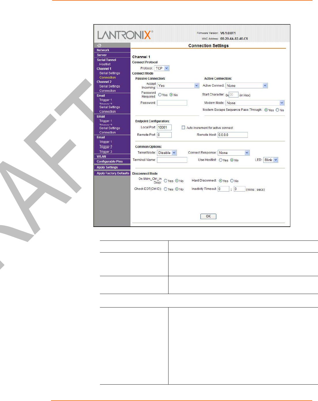
Connection Settings - TCP
To configure a channel’s TCP settings:
1. From the main menu, click Connection for either Channel 1 or Channel 2 to
display the Connection Settings page for the selected channel.
2. In the available fields, enter the following information:
Connect Protocol
Protocol Select TCP from the pull down menu.
Configuration Using Web-Manager
WiPort™ User Guide 24
Figure 4-6. TCP Connection Settings
Connect Mode: Passive Connection
Accept Incoming Select Yes to accept incoming connections.
Password Required Determines whether a password is required for an incoming
passive connection. Field is not available when a password is
set for Telnet mode.
Password If Password Required was set to Yes, enter the password for
passive connections.
Connect Mode: Active Connection
Active Connect Select None to disable Active Connect. Otherwise, indicate
the connection type from the drop-down list:
With Any Character: Attempts to connect when any
character is received from the serial port.
With Active Mdm Ctrl In: Accepts external
connection requests only when the
modem_control_in input is asserted.
With Start Character:
Attempts to connect when it

Configuration Using Web-Manager
WiPort™ User Guide 25
receives a specific start character from the serial
port. The default start character is carriage return.
Manual Connection: Attempts to connect when
directed by a command string received from the
serial port.
Auto Start: Automatically connects to the remote IP
address and port after booting up.
Start Character If Active Connect is set to With Start Character, enter the
start character in this field.
Modem Mode Indicates the on-screen response type when in Modem Mode
(if Modem Mode is enabled).
Endpoint Configuration
Local Port Enter the local port number.
Auto increment local
port number Select to auto-increment the local port number for new
outgoing connections. The range of auto-incremented port
numbers is 50,000 to 59,999 and loops back to the beginning
when the maximum range is reached.
Remote Port Enter the remote port number.
Remote Host Enter the IP address of the remote device.
Common Options
Telnet Mode This field is available for configuration only when Active
Connection is not set to None. Select Enable to permit Telnet
communication to the WiPort unit.
Terminal Name This field is available for configuration only when Telnet Mode
is set to Enable.
Use the terminal name for the Telnet terminal type. Enter only
one name. When this option is enabled, the unit also reacts to
the EOR (end of record) and binary options, which can be
used for applications such as terminal emulation to IBM hosts.
Connect Response A single character is transmitted to the serial port when there
is a change in connection state. Default setting is None.
Use Hostlist If this option is set to True, the device server scrolls through
the host list until it connects to a device listed in the host list
table. Once it connects, the unit stops trying to connect to any
others. If this connection fails, the unit continues to scroll
through the table until it is able to connect to another IP in the
host list.
The host list is disabled for Manual Mode and for Modem
Mode. The unit will not accept a data connection from a
remote device when the host list option is enabled.
For information on configuring the host list, see Host List
Configuration on page 20.
LED Select Blink for the status LEDs to blink u
p
on connection or

Configuration Using Web-Manager
WiPort™ User Guide 26
None for no LED output.
Disconnect Mode
On Mdm_Ctrl_In Drop Set to Yes for the network connection to or from the serial port
to drop when modem_control_in transitions from a high state
to a low state.
Hard Disconnect When set to Yes, the TCP connection closes even if the
remote site does not acknowledge the disconnect request.
With EOT Choose Yes to drop the connection when Ctrl-D or Hex 04 is
detected. Both Telnet mode and Disconnect with EOT must
be enabled for Disconnect with EOT to function properly. Ctrl
D is only detected going from the serial port to the network.
Inactivity Timeout Use this parameter to set an inactivity timeout. The unit drops
the connection if there is no activity on the serial line before
the set time expires. Enter time in the format mm:ss, where m
is the number of minutes and s is the number of seconds. To
disable the inactivity timeout, enter 00:00.
Connection Settings - UDP
To configure a channel’s UDP settings:
1. From the main menu, click Connection for either Channel 1 or Channel 2 to
display the Connection Settings page for the selected channel.
2. In the available fields, enter the following information:
Connect Protocol
Protocol Select UDP from the pull down menu.
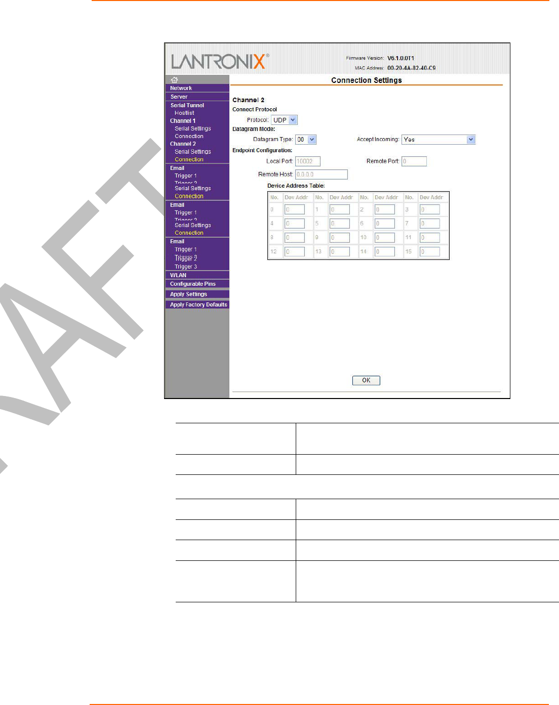
Configuration Using Web-Manager
WiPort™ User Guide 27
Figure 4-7. UDP Connection Settings
Datagram Mode
Datagram Type Configures remote IP or network broadcast address and the
remote port. Enter 01 for directed or broadcast UDP.
Accept Incoming Select Yes to accept incoming UDP datagrams.
Endpoint Configuration
Local Port Enter the local port number.
Remote Port Enter the port number of the remote device.
Remote Host Enter the IP address of the remote device.
Change Address Table Field enabled when Datagram Type is set to FD. Enter values
between 1-255 to identify units on the local network of device
servers.
Email Configuration
The unit sends an Email to multiple recipients when a specific trigger event occurs.
There are three separate triggers, based on any combination of the configurable pins
when selected as user I/O functions. Optionally, use a two-byte serial string to initiate

Configuration Using Web-Manager
WiPort™ User Guide 28
a trigger. Each trigger is independent of the others. Each condition within an
individual trigger must be met before the unit will send the Email.
To configure the WiPort’s email settings:
1. From the main menu, select Email to open the Email Settings window.
Figure 4-8. Email Settings
2. Configure the following fields:
Server IP Address Enter the IP address of the mail server.
Domain Name Enter the Email server’s domain name.
Unit Name Enter the username used by the WiPort to send Email
messages.
Recipients
Recipient 1: Email
Address Enter the email address designated to receive email
notifications.
Recipient 2: Email
Address Enter an additional email address designated to receive email
notifications.
Trigger Configuration
A trigger event occurs when the unit receives the specified trigger input as a result of
a specified combination of conditions on the configurable pins.
Set the configurable pins to Active, Inactive, or None. The configurable pins are
disabled if they are all set to None. If both the serial sequence and the configurable
pins are disabled, the trigger is disabled.
To configure the WiPort’s email trigger settings:
1. From the main menu, select Trigger 1, Trigger 2, or Trigger 3 to configure the
desired Trigger settings. The Email Trigger Settings page opens.
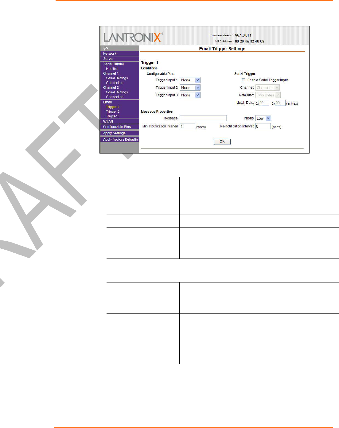
Configuration Using Web-Manager
WiPort™ User Guide 29
Figure 4-9. Email Trigger Settings
2. Configure the following fields:
Conditions
Configurable Pins Select the condition from the pull down menu for the
configurable pins. Repeat for each Trigger Input field.
Enable Serial Trigger
Input When selected, specified serial communications count as a
trigger input.
Channel Select the channel prompting the trigger.
Data Size Select the data size prompting the trigger.
Match Data Enter the data which, when appears in the communication
stream, prompts a trigger.
Note: All of the conditions must match for an email notification to be sent.
Message Properties
Message The subject line of the trigger event email to the specified
recipient(s).
Priority The priority level for the e-mail.
Notification Interval The notification interval is the minimum time allowed between
individual triggers. If a trigger event occurs within the
minimum interval since the last trigger, it is ignored.
Re-notification Interval Indicates the time interval in which a new email message is
sent to the recipient(s) when a single trigger event remains
active.
WLAN Configuration
Without adequate protection, a wireless LAN is susceptible to access by
unauthorized users.
To configure the WiPort’s WLAN settings:
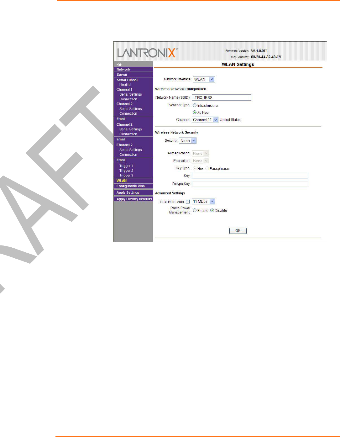
Configuration Using Web-Manager
WiPort™ User Guide 30
1. Select WLAN from the main menu to open the WLAN Settings window.
Figure 4-10. WLAN Settings

Configuration Using Web-Manager
WiPort™ User Guide 31
2. Enter or modify the following fields:
Network Interface Use the pull down menu to select a WLAN interface or an
Ethernet interface.
Note: Fields on this page are not modifiable when Ethernet is
selected.
Wireless Network Configuration
Network Name Enter the name of the wireless network (SSID). The WiPort
connects to this wireless network.
Network Type Select Infrastructure or Ad-Hoc.
Channel Configurable only when Network Type is set to Ad-Hoc.
Select from the pull down menu the radio channel for the Ad
Hoc network. The default value is 11.
Wireless Network Security
Security As a security measure, enable WEP or WPA on the WiPort.
By default, wireless security is disabled on WiPort.
WEP Options
Authentication Field is enabled when WEP or WPA is selected as the
Security type. Select an authentication scheme (Open/None
or Shared) from the drop down menu.
Encryption Field is enabled when WEP or WPA is selected as the
Security type. Select the encryption type (64 bits or 128 bits
for WEP) from the pull down menu. 64 bits is the default
encryption for WEP.
Key Type Field is enabled when WEP or WPA is selected as the
Security type. Select the key type (Hex or Passphrase).
Key Field is enabled when WEP or WPA is selected as the
Security type. Enter the Encryption Key in hexadecimal
value if Hex is selected as the Key Type. Enter key as a
string if Passphrase is selected as the Key Type. Passphrase
input is not the same as ASCII input
WPA Options
Authentication Field is enabled when WEP or WPA is selected as the
Security type. Select Pre-Shared Keys from the drop down
menu.
Encryption Field is enabled when WEP or WPA is selected as the
Security type. Select the encryption type from the pull down
menu. TKIP is the default encryption for WPA.
Key Type Field is enabled when WEP or WPA is selected as the
Security type. Select the key type (Hex or Passphrase).
Key Field is enabled when WEP or WPA is selected as the
Security type. Enter the Encryption Key in hexadecimal
value if
Hex
is selected as the Key Type Enter key as a

Configuration Using Web-Manager
WiPort™ User Guide 32
string if Passphrase is selected as the Key Type. Passphrase
input is not the same as ASCII input
Advanced Settings
Data Rate WiPort permits the control of the data transmission rate. Click
the Auto check box to allow the WiPort to automatically set
the data rate (or leave unchecked to manually set the
transmission rate). The default rate is 11 Mbps.
If the Auto check box is selected, choose the data rate from
the drop down menu. This is the WiPort’s maximum data rate.
If the Auto check box was not selected, select the data rate
(in Mbps) from the drop down menu. This is the WiPort’s fixed
rate.
Note: For WiPort version WP2001000G-02 (WiPort-G), the
maximum data rate cannot be selected when the WiPort
automatically sets the data rate. WiPort-G supports the
following additional rates: 18 Mbps, 24 Mbps, 36 Mbps, and
54 Mbps.
Radio Power
Management Power management reduces the overall power consumption
of the WiPort unit. Selecting Enable increases the response
time.
TX Power Level Note: Available on WiPort version WP2001000G-02 (WiPort-
G).
Select the transmission power level from the drop down menu.
Higher values span a wider range. The default is 18 dBm.
Configurable Pin Settings
There are 11 configurable hardware pins on the WiPort unit. For each pin, configure
the pin function, communication direction, and its activity level. For more information,
see Configurable Pins on page 64.
To configure the WiPort’s OEM Configurable Pins:
1. Click Configurable Pins from the main menu to open the Configurable Pins
window.
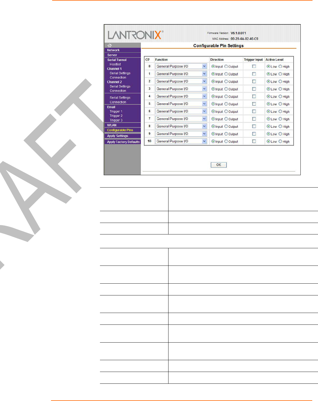
Configuration Using Web-Manager
WiPort™ User Guide 33
Figure 4-11. Configurable Pins Settings
2. Configure or modify the following fields for each pin:
Function From the pull down menu, select the purpose of the specified
pin. See Configurable Pin Functions for a description of each
available function.
Active Level Select the signal active level (Low or High).
Direction Select whether the pin inputs or outputs.
Configurable Pin Functions
General Purpose I/O Monitors input via the 77F0 port or controls output by the 77F0
port.
Modem Ctrl in, chan 1 Allows for control of the connection (and disconnection) of
channel 1.
Modem Ctrl out, chan 1 Indicates a connection is established on channel 1.
Modem Ctrl in, chan 2 Allows for control of the connection (and disconnection) on
channel 2.
Modem Ctrl out, chan 2 Indicates a connection is established on channel 2.
Serial Status LED out,
chan 1 Indicates channel 1 status and extended diagnostics when the
Diagnostics LED is lit.
Serial Status LED out,
chan 2 Indicates channel 2 status.
Diagnostics LED out Indicates errors and configurations.
Reset to Defaults in Allows the external si
g
nal to reset the confi
g
uration back to

Configuration Using Web-Manager
WiPort™ User Guide 34
system default during bootup. Used when network access is
impossible on account of improper configuration.
RS-485 Select out Selects between RS-232 and RS-485 line drivers. Applies to
WiPort-485 only.
RS-485 2 Wire out Selects 2-wire line drivers. Usable as a half/full duplex
selector. Applies to WiPort-485 only.
RS-422/485 4 Wire out Selects 4-wire line drivers. Applies to WiPort-485 only.
Updating Settings
Click the Apply Settings button from the main menu to save and apply the
configuration changes.
Applying Factory Default Settings?
Click the Apply Factory Defaults? button from the main menu to apply the factory
settings to the WiPort. For a list of the default settings, refer to Default Settings on
page 61.

WiPort™ User Guide 35
5
5:
:
C
Co
on
nf
fi
ig
gu
ur
ra
at
ti
io
on
n
v
vi
ia
a
S
Se
er
ri
ia
al
l
M
Mo
od
de
e
o
or
r
T
Te
el
ln
ne
et
t
P
Po
or
rt
t
Configure the unit so that it can communicate on a network with your serial device.
As an alternative to Web-Manager, the WiPort unit is configurable using a terminal
program to access the serial port locally. Using this terminal program to respond to
prompts is referred to as the Setup Mode. A Telnet connection may also be used to
configure the unit over the network.
The unit’s configuration is stored in nonvolatile memory and is retained without
power. You can change the configuration at any time. The unit performs a reset after
the configuration has been changed and stored.
Note: The menus in this section show a typical device. Not all devices
display information in the same manner.
Accessing Setup Mode
Telnet Access
Note: Alternatively, use DeviceInstaller to access Telnet. Select the device from the
main window list, and click the Telnet Configuration tab in the right window. If using
Telnet from the DeviceInstaller toolbar, skip steps 1 through 3.
To configure the unit over the network, establish a Telnet connection to port 9999:
1. From the Windows Start menu, click Run.
2. From the Run dialogue box, type the following command (where x.x.x.x is the IP
address and 9999 is the unit’s fixed network configuration port number):
Windows: telnet x.x.x.x 9999
UNIX: telnet x.x.x.x:9999
3. Click OK. The following information displays:
Figure 5-1. MAC Address
MAC address 00204AFFFF30
Software version V6.0.0.0 (050214)
Press Enter to go into Setup Mode
4. To enter the Setup Mode, press Enter within 5 seconds.
Note: Connection fails if Enter is not pressed within 5 seconds.
The configuration settings display, followed by the setup menu options:

Configuration via Serial Mode or Telnet Port
WiPort™ User Guide 36
Figure 5-2. Setup Menu Options
Change Setup:
0 Server
1 Channel 1
2 Channel 2
3 Email
4 WLAN
5 Expert
6 Security
7 Defaults
8 Exit without save
9 Save and exit Your choice ?
5. Select an option on the menu by entering the number of the option in the Your
choice ? field and pressing Enter.
View the current configuration by pressing Enter from the Change Setup menu.
To enter a value for a parameter, type the value and press Enter. To confirm a
current value, press Enter (without inputted parameters).
6. When finished, save the new configurations (9 Save and exit). The unit reboots.
Serial Port Access
To configure the unit through a serial connection:
1. Connect a console terminal or PC running a terminal emulation program to your
unit's serial port. The default serial port settings are 9600 baud, 8 bits, no parity,
1 stop bit, no flow control.
2. Reset the WiPort unit by cycling the unit's power (turning the power off and back
on). Immediately upon resetting the device, enter three lowercase x characters
(xxx).
Note: The easiest way to enter Setup Mode is to hold down the x key at
the terminal (or emulation) while resetting the unit. This must be done
within three seconds of resetting the WiPort.
3. Upon connection, the following information displays:
Figure 5-3. MAC Address
MAC address 00204AFFFF30
Software version V6.0.0.0 (050214)
Press Enter to go into Setup Mode
4. To enter the Setup Mode, press Enter within 5 seconds.
Note: Connection fails if Enter is not pressed within 5 seconds.
The configuration settings display, followed by the setup menu options:
Figure 5-4. Setup Menu Options
Change Setup:
0 Server
1 Channel 1
2 Channel 2
3 Email
4 WLAN
5 Expert

Configuration via Serial Mode or Telnet Port
WiPort™ User Guide 37
6 Security
7 Defaults
8 Exit without save
9 Save and exit Your choice ?
5. Select an option on the menu by entering the number of the option in the Your
choice ? field and pressing Enter.
View the current configuration by pressing Enter from the Change Setup menu.
To enter a value for a parameter, type the value and press Enter. To confirm a
current value, press Enter (without inputted parameters).
6. When finished, save the new configurations (9 Save and exit). The unit reboots.
Server Configuration
The unit’s basic server (i.e. network) values display upon selecting Server (option 0
from the Change Setup menu). The following sections describe the configurable
parameters within the Server configuration menu.
Set the IP Address
If DHCP is not used to assign IP addresses, enter it manually. The IP address must
be set to a unique value in the network. Enter each octet and press Enter between
each section inputted. The current value is displayed in parentheses.
IP Address : ( 0) ( 0) ( 0) ( 0) _
Set the Gateway IP Address
The gateway address, or router, allows communication to other LAN segments. The
gateway address should be the IP address of the router connected to the same LAN
segment as the unit. The gateway address must be within the local network.
The default is N (No), indicating the gateway address has not been set. To set the
gateway address, type Y. At the prompt, enter the gateway address.
Set Gateway IP Address (N) ? Y
Gateway IP addr ( 0) ( 0) ( 0) ( 0)_
Set the Netmask
A netmask defines the number of bits taken from the IP address that are assigned for
the host part.
Netmask: Number of Bits for Host Part (0=default) (0) _
The unit prompts for the number of host bits to be entered, then calculates the
netmask, which displays in standard decimal-dot notation when the saved
parameters are displayed (for example, 255.255.255.0).

Configuration via Serial Mode or Telnet Port
WiPort™ User Guide 38
Table 5-1. Standard IP Network Netmasks Representing Host Bits
Network Class Host Bits Netmask
A 24 255.0.0.0
B 16 255.255.0.0
C 8 255.255.255.0
Change Telnet Configuration Password
Setting the Telnet configuration password prevents unauthorized access to the setup
menu via a Telnet connection to port 9999 or via web pages. The password must
have 4 characters.
Change telnet config password (N) ? _
An enhanced password setting (for Telnet access only) of 16 characters is available
under option 6 Security from the Change Setup menu.
Note: A password is not required to access the Setup Mode window via a
serial connection.
DHCP Name
If a DHCP server has automatically assigned the IP address and network settings,
discover the unit by using the DeviceInstaller network search feature.
There are three methods for assigning DHCP names to the unit.
Default DHCP Name: If the DHCP name is not changed and the IP is
0.0.0.0, then the DHCP name defaults to CXXXXXX (XXXXXX is the last 6
digits of the MAC address shown on the label on the bottom/side of the unit).
For example, if the MAC address is 00-20-4A-12-34-56, then the default
DHCP name is C123456.
Custom DHCP Name: Create your own DHCP name. If using an IP address
of 0.0.0.0, then the last option in Server configuration is Change DHCP
device name. This option allows you to change the DHCP name to an
alphanumeric name (LTX in the example).
Change DHCP device name (not set) ? (N) Y
Enter new DHCP device name : LTX
Numeric DHCP Name: You can change the DHCP name by specifying the
last octet of the IP address. When you use this method, the DHCP name is
LTXYY where YY is what you chose for the last octet of the IP address. If the
IP address you specify is 0.0.0.12, then the DHCP name is LTX12. This
method only works with 2 digit numbers (0-99). SHOULD IT BE 10-99?
The third octet of the IP address sets the BootP/DHCP/AutoIP options. To
disable an option, set the appropriate bit:
5-2. BootP/DHCP/AutoIP options
Options Bit
AutoIP 0
DHCP 1
Configuration via Serial Mode or Telnet Port
WiPort™ User Guide 39
Options Bit
BootP 2
For example, if the third octet is 0.0.5.0, the AutoIP and BootP options are
disabled; only DHCP is enabled. (The value 5 results from adding the binary
equivalents of 0 and 2.) This is the most common setting when using DHCP.
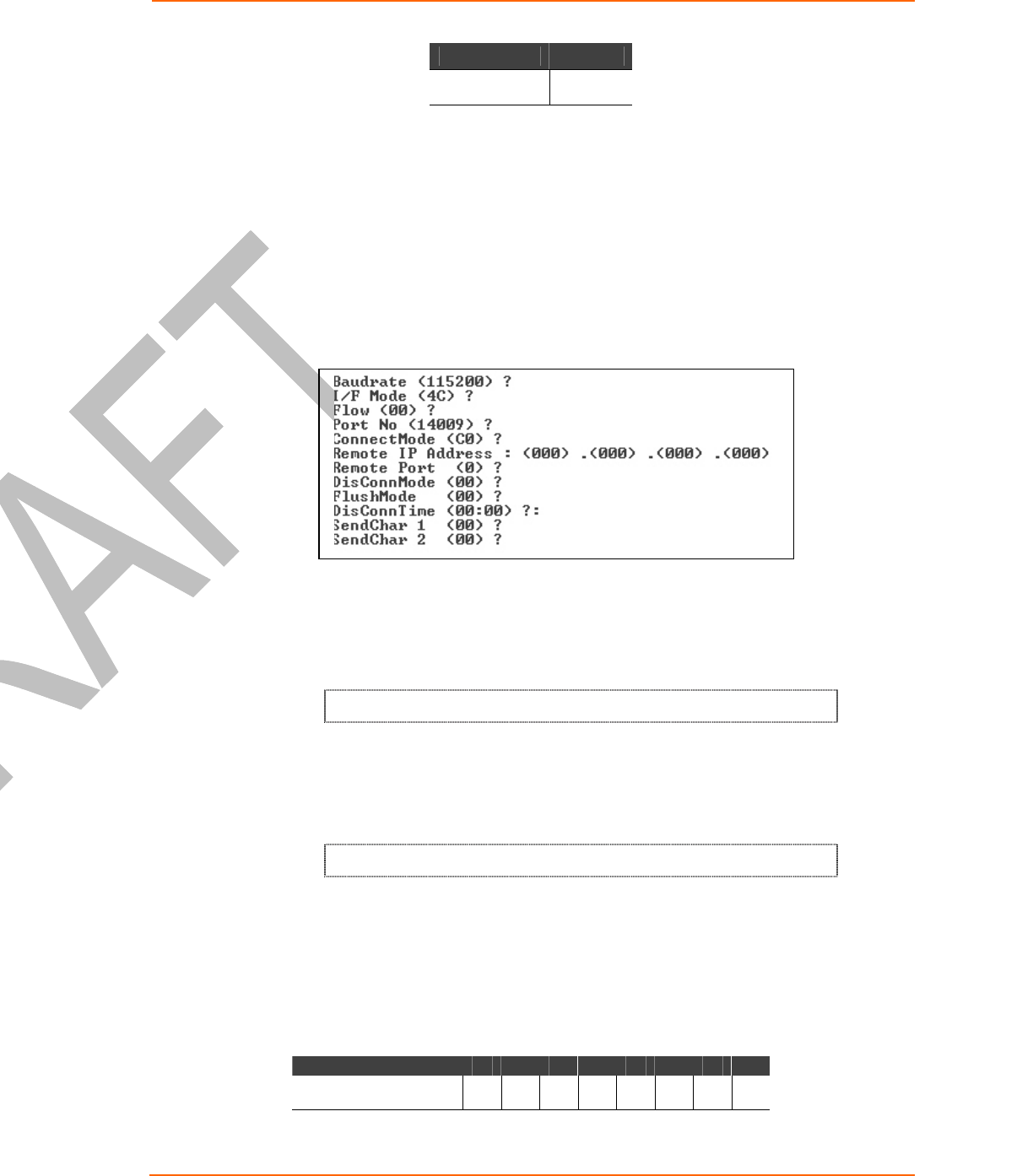
Channel 1 and Channel 2 Configuration
Select option 1 Channel 1 or 2 Channel 2 from the Change Setup menu to define
how the serial port responds to network and serial communications. The following
sections describe the configurable parameters within the Channel configuration
menu.
Figure 5-5. Serial and Telnet Port Parameters
Baudrate
The unit and attached serial device, such as a modem, must agree on a speed or
baud rate to use for the serial connection. Valid baud rates are 300, 600, 1200, 2400,
4800, 9600 (default), 19200, 38400, 57600, 115200, 230400, 460800, or 921600.
The current value is displayed in parentheses.
Baudrate (9600) ? _
I/F (Interface) Mode
The Interface (I/F) Mode is a bit-coded byte entered in hexadecimal notation. The
current value is displayed in parentheses.
I/F Mode (4C) ? _
Note: RS-422 and RS-485 are available on Channel 2 only (WiPort-485
models) if the WiPort is used with the WiPort evaluation board. Otherwise,
RS-422 and RS-485 functions are available on only one channel; depending
on which channel the drivers were added, these functions are available on
either channel 1 or channel 2.
The following table displays available I/F Mode options:
Table 5-3. Interface Mode Options
I/F Mode Option 7 6 5 4 3 2 1 0
RS-232 (1) 0 0

Configuration via Serial Mode or Telnet Port
WiPort™ User Guide 40
I/F Mode Option 7 6 5 4 3 2 1 0
RS-422/485 4-wire(2) 0 1
RS-485 2-wire(2) 1 1
7 Bit 1 0
8 Bit 1 1
No Parity 0 0
Even Parity 1 1
Odd Parity 0 1
1 stop bit 0 1
2 stop bits(1) 1 1
(1) 2 stop bits are implemented by the software. This might influence performance.
(2) On WP2004000-01 (WiPort-485) only.
Note: If attempting to select an I/F Mode bit pertaining to RS-422/485 on a
WiPort model WP2001000-01, a “WARNING: RS-422/485 I/F Modes not
supported” message displays. RS-422/485 settings are available on the
WP2004000-01 (WiPort-485).
The following table demonstrates some common I/F Mode settings:
Table 5-4. Common Interface Mode Settings
Common I/F Mode Setting Binary Hex
RS-232C, 8-bit, No Parity, 1 stop bit 0100 1100 4C
RS-232C, 7-bit, Even Parity, 1 stop bit 0111 1000 78
RS-485 2-wire, 8-bit, No Parity, 1 stop
bit 0100 1111 4F
RS-422, 8-bit, Odd Parity, 1 stop bit 0101 1101 5D
Flow
Flow control sets the local handshaking method for stopping serial input/output. The
current value is displayed in parentheses.
Flow (0) ? _
Use the following table to select flow control options:
Table 5-5. Flow Control Options
Flow Control Option Hex
No flow control 00
XON/XOFF flow control 01
Hardware handshake with RTS/CTS lines 02

Configuration via Serial Mode or Telnet Port
WiPort™ User Guide 41
Flow Control Option Hex
XON/XOFF pass characters to host 05
Port Number
The Port No setting represents the source port number in TCP connections. It is the
number that identifies the channel for remote initiating connections. The port number
functions as the TCP/UDP source port number for outgoing packets. Packets sent to
the unit with this port number are received to this channel. The port number selected
is the Incoming TCP/UDP port and Outgoing TCP/UDP source port.
Port No (10001) ? _
The current value is displayed in parentheses. The default setting for Port 1 is 10001.
The range is 1-65535, except for the following reserved port numbers:

Configuration via Serial Mode or Telnet Port
WiPort™ User Guide 42
Table 5-6. Reserved Port Numbers
Port Numbers Reserved for
1 – 1024 Reserved
9999 Telnet setup
14000-14009 Reserved for Redirector
30704 Reserved (77F0h)
30718 Reserved (77FEh)
Note: It is recommended to not use the reserved port numbers for this
setting as incorrect operation may result.
Use Port 0 for the outgoing local port to change with each connection. The port range
is 50,000 to 59,999. Each subsequent connection increments the number by 1 (it
wraps back around to 50,000).
Only use this automatic port increment feature to initiate a connection using TCP. Set
the port to a non-zero value when the unit is in a passive mode or when using UDP
instead of TCP.
Connect Mode
Connect Mode defines the unit’s connection method and its reaction to incoming
connections over the network. The current value is displayed in parentheses.
ConnectMode (C0) ? _
Enter Connect Mode options in hexadecimal notation:
Table 5-7. Connect Mode Options
Connect Mode Option 7 6 5 4 3 2 1 0
a) Incoming Connection
Never accept incoming 0 0 0
Accept with modem_control_in Active 0 1 0
Always Accept 1 1 0
b) Response
Nothing (quiet) 0
Character response (C=connect,
D=disconnect, N=unreachable) 1
c) Active Startup
No active startup 0 0 0 0
With any character 0 0 0 1
With modem_control_in Active 0 0 1 0
With a specific start character 0 0 1 1

Configuration via Serial Mode or Telnet Port
WiPort™ User Guide 43
Connect Mode Option 7 6 5 4 3 2 1 0
Manual connection 0 1 0 0
Autostart 0 1 0 1
Hostlist 0 0 1 0
d) Datagram Type
Directed UDP 1 1 0 0
e) Modem Mode
No Echo 0 0 1 1
Data Echo & Modem Response
(Numeric) 0 1 1 1 1
Data Echo & Modem Response
(Verbose) 0 1 1 1 0
Modem Response Only (Numeric) 0 0 1 1 1 1
Modem Response Only (Verbose) 0 0 1 1 1 0
a) Incoming Connection
Never Accept Incoming Rejects all external connection attempts.
Accept with
modem_control_in
Active
Accepts external connection requests only when the
modem_control_in input is asserted. Cannot be used with
Modem Mode.
Always Accept Accepts any incoming connection when a connection is not
already established. Default setting.
b) Response
Character Response A single character is transmitted to the serial port when there is a
change in connection state:
C = connected, D = disconnected, N = host unreachable.
This option is overridden when the Active Start Modem Mode or
Active Start Host List is in effect. Default setting is Nothing
(quiet).
No Active Startup Does not attempt to initiate a connection. Default setting.
With Any Character Attempts to connect when any character is received from the
serial port.
Accept with
modem_control_in
Active
Attempts to connect when the modem_control_in input changes
from not asserted to asserted.
With a Specific Start
Character Attempts to connect when it receives a specific start character
from the serial port. The default start character is carriage return.

Configuration via Serial Mode or Telnet Port
WiPort™ User Guide 44
Manual Connection Attempts to connect when directed by a command string
received from the serial port. The first character of the command
string must be a C (ASCII 0x43), and the last character must be
either a carriage return (ASCII 0x0D) or a line feed (0x0A). No
blanks or space characters may be in the command string.
Between the first and last command string characters must be a
full or partial destination IP address and can include a
destination port number.
The IP address must be in standard dot-decimal notation and
may be a partial address, representing the least significant 1, 2,
or 3 bytes of the remote IP address. The period is required
between each pair of IP address numbers.
If present, the port number must follow the IP address, must be
presented as a decimal number in the range 1-65535, and must
be preceded by a forward slash (ASCII 0x2F). The slash
separates the IP address and the port number. If you omit the
port number from a command string, the internally stored remote
port number starts a connection.
If a partial IP address is presented in a command string, it is
interpreted to be the least significant bytes of the IP address and
uses the internally stored remote IP address to provide the most
significant bytes of the IP address. If the IP address entered is
0.0.0.0/0, the device server enters Monitor Mode.
For example, if the remote IP address already configured in the
unit is 129.1.2.3, then an example command string would be
C3/7. (This would connect to 129.1.2.3 and port 7.) You may
also use a different ending for the connection string. For
example, C50.1/23 would connect you to 129.1.50.1 and port 23.
Table 5-8. Manual Connection Address Example
Command String Result if remote IP is 129.1.2.3 and remote port is 1234
C121.2.4.5/1 Complete override; connection is started with host 121.2.4.5, port 1
C5 Connects to 129.1.2.5, port 1234
C28.10/12 Connects to 129.1.28.10, port 12
C0.0.0.0/0 Connects to 129.1.28.10, port 12; enters Monitor Mode
Autostart (Automatic
Connection) The unit automatically attempts a connection to the remote IP
address and port after booting up.

Configuration via Serial Mode or Telnet Port
WiPort™ User Guide 45
Hostlist If this option is set to True, the device server scrolls through the
host list until it connects to the first available device listed in the
host list table. Once it connects, the unit stops further attempts. If
this connection fails, the unit continues to scroll through the table
until it is able to connect to the next available IP address in the
host list.
Hostlist supports a minimum of 1 and a maximum of 12 entries.
Each entry contains the IP address and the port number.
The hostlist is disabled for Manual Mode and for Modem Mode.
The unit will not accept a data connection from a remote device
when the hostlist option is enabled.
Figure 5-6. Hostlist Example
Baudrate (9600) ?
I/F Mode (4C) ?
Flow (00) ?
Port No (10001) ?
ConnectMode (C0) ?25
Hostlist :
No Entry !
Change Hostlist ? (N) Y
01. IP address : (000) 172.(000) 19.(000) 0.(000) 1 Port :
(0) ?23
02. IP address : (000) 172.(000) 19.(000) 0.(000) 2 Port :
(0) ?3001
03. IP address : (000) 172.(000) 19.(000) 0.(000) 3 Port :
(0) ?10001
04. IP address : (000) .(000) .(000) .(000)
Hostlist :
01. IP : 172.019.000.001 Port : 00023
02. IP : 172.019.000.002 Port : 03001
03. IP : 172.019.000.003 Port : 10001
Change Hostlist ? (N) N
Hostlist Retrycounter (3) ?
Hostlist Retrytimeout (250) ?
DisConnMode (00) ?
FlushMode (00) ?
DisConnTime (00:00) ?:
SendChar 1 (00) ?
SendChar 2 (00) ?
To enable the hostlist:
1. Enter a Connect Mode of 0x20. The menu shows a list of current entries already
defined in the product.
2. To delete, modify, or add an entry, select Yes. If entering an IP address of
0.0.0.0, that entry and all others after it are deleted.
3. After completing the hostlist, repeat the previous step if necessary to edit the
hostlist again.

Configuration via Serial Mode or Telnet Port
WiPort™ User Guide 46
4. For Retrycounter, enter the number of times the Lantronix unit should try to
make a good network connection to a hostlist entry that it has successfully
ARPed. The range is 1-15, with the default set to 3.
5. For Retrytimeout, enter the number of seconds the unit should wait before
failing an attempted connection. The time is stored as units of milliseconds in the
range of 1-65535. The default is 250.
c) Datagram Type
Directed UDP When selecting this option, the prompt requests the Datagram type.
Enter 01 for directed or broadcast UDP.
When the UDP option is in effect, the unit uses UDP datagrams to
send and receive data.
d) Modem Mode
In Modem (Emulation) Mode, the unit presents a modem interface to the attached
serial device. It accepts AT-style modem commands, and handles the modem signals
correctly.
Normally, there is a modem connected to a local PC and a modem connected to a
remote machine. A user must dial from the local PC to the remote machine,
accumulating phone charges for each connection. Modem Mode allows you to
replace modems with WiPorts, and to use an Ethernet connection instead of a phone
call. By not having to change communications applications, you avoid potentially
expensive phone calls.
To select Modem Mode, set the Connect Mode to C6 (no echo), D6 (echo with full
verbose), or D7 (echo with numeric response).
Note: If the unit is in Modem Mode, and the serial port is idle, the unit can
still accept network TCP connections to the serial port if Connect Mode is set
to C6 (no echo), D6 (echo with full verbose), or D7 (echo with numeric
response).
Without Echo In Modem Mode, echo refers to the echo of all of the characters
entered in command mode; it does not mean to echo data that is
transferred. Quiet Mode (without echo) refers to the modem not
sending an answer to the commands received (or displaying what
was typed).
Data Echo & Modem
Response Full Verbose: The unit echoes modem commands and responds
to a command with a message string shown in the table below.
Numeric Response: The unit echoes modem commands and
responds to a command with a numeric response.
Modem Responses
Only Full Verbose: The unit echoes modem commands and responds to
a command with a message string shown in the table below.
Numeric Response: The unit echoes modem commands and
responds to a command with a numeric response.

Configuration via Serial Mode or Telnet Port
WiPort™ User Guide 47
Table 5-9. Modem Mode Messages
Message Meaning
Full Verbose
OK Command was executed without error.
CONNECT A network connection has been established.
NO CARRIER A network connection has been closed.
RING n.n.n.n. A remote device, having IP address n.n.n.n, is connecting to this
device.
Numeric Response
0 OK
1 Connected
2 Ring
3 No Carrier
4 Error
Received commands must begin with the two-character sequence AT and be
terminated with a carriage return character.
The unit ignores any character sequence received not starting with AT, and only
recognizes and processes single AT-style commands. The unit treats compound AT
commands as unrecognized commands.
If the Full Verbose option is in effect, the unit responds to an unrecognized
command string that is otherwise formatted correctly (begins with AT and ends with
carriage return) with the "OK" message and takes no further action.
If the Numeric Response option is in effect, the unit responds to an unrecognized
command string that is otherwise formatted correctly with the "OK" message and
takes no further action.
When an active connection is in effect, the unit transfers data and does not process
commands received from the serial interface.
When a connection is terminated or lost, the unit reverts to command mode.
When an active connection is in effect, the unit terminates the connection if it
receives the following sequence from the attached serial device:
No serial data is received for one second.
The character sequence +++ is received, with no more than one second
between each two characters.
No serial data is received for one second after the last + character. At this
time, the unit responds affirmatively per the selected echo/response mode.
The character string ATH is received, terminated with a carriage return. The
unit responds affirmatively according to the selected echo/response mode
and drops the network connection. The serial interface reverts to accepting
command strings.

Configuration via Serial Mode or Telnet Port
WiPort™ User Guide 48
If this sequence is not followed, the unit remains in data transfer mode.
Table 5-10. Modem Mode Commands
Modem Mode
Command Function
ATDTx.x.x.x,pppp or
ATDTx.x.x.x/pppp
Makes a connection to an IP address (x.x.x.x) and a remote port
number (pppp).
ATDTx.x.x.x Makes a connection to an IP address (x.x.x.x) and the remote port
number defined within the unit.
ATD0.0.0.0 Forces the unit into Monitor Mode. Uses remote IP address and
port settings to initiate a connection.
ATD or ATDT Forces the unit into Monitor Mode. Uses remote IP address and
port settings to initiate a connection.
ATDx.x.x.x Makes a connection to an IP address (x.x.x.x) and the remote port
number defined within the unit.
ATH Hangs up the connection (Entered as +++ ATH ).
ATS0=n
Enables or disables connections from the network going to the
serial port.
n=0 disables the ability to make a connection from the network to
the serial port.
n=1-9 enables the ability to make a connection from the network
to the serial port.
n>9 is invalid.
ATEn
Enables or disables character echo and responses.
n=0 disables character echo and responses.
n=1 enables character echo and responses.
ATVn
Enables numeric response or full verbose.
n=0 enables numeric response.
n=1 enables full verbose.
Note: The unit recognizes these AT commands as single commands such as
ATE0 or ATV1; it does not recognize compound commands such as ATE0V.
Send the Escape Sequence (+++) in Modem Mode
Send ‘+++’ in Modem Mode (Y) ? _
Disable or enable the WiPort’s ability to send the escape sequence. The default is Y
(Yes) (send the escape sequence).
Auto Increment Source Port
Auto increment source port (N) ? _
Y (Yes) auto increment the source port. The WiPort increments the port number used
with each new connection.
Remote IP Address
This is the destination IP address used with an outgoing connection.

Configuration via Serial Mode or Telnet Port
WiPort™ User Guide 49
Remote IP Address : ( 0) ( 0) ( 0) ( 0)_
Note: This option is not displayed when Hostlist is enabled from the
ConnectMode prompt (see Error! Reference source not found. on page
42 for more information).
Remote Port
You must set the remote TCP port number for the unit to make outgoing connections.
This parameter defines the port number on the target host to which a connection is
attempted.
Remote Port ( 0) ? _
To connect an ASCII terminal to a host using the unit for login purposes, use the
remote port number 23 (Internet standard port number for Telnet services).
Note: This option is not displayed when Hostlist is enabled from the
ConnectMode prompt (see Error! Reference source not found. on page 42
for more information).
DisConnMode
Disconnect Mode (DisConnMode) determines the conditions under which the unit will
cause a network connection to terminate. The current value is displayed in
parentheses.
DisConnMode ( 0) ? _
In DisConnMode, modem_control_in either drops the connection or is ignored. The
following table displays the available input options:
Table 5-11. Disconnect Mode Options
Disconnect Mode Option 7 6 5 4 3 2 1 0
Disconnect with
modem_control_in drop (6) 1
Ignore modem_control_in 0
Telnet mode and terminal type
setup (1) 1
Channel (port) password (2) 1
Hard disconnect (3) 0
Disable hard disconnect 1
State LED off with connection (4) 1
Disconnect with EOT (^D) (5) 1
(1) The WiPort sends the "Terminal Type" upon an outgoing connection.
(2) A password is required for a connection to the serial port from the network.
(3) The TCP connection closes even if the remote site does not acknowledge the disconnection.
(4) When there is a network connection to or from the serial port, the state LED turns off instead of blinking.
(5) When Ctrl D or Hex 04 is detected, the connection is dropped. Both Telnet mode and Disconnect with
EOT must be enabled for Disconnect with EOT to function properly. Ctrl D is only detected going from the
serial port to the network.
(6) When modem_control_in transitions from a high state to a low state, the network connection to or from the
serial port drops.

Configuration via Serial Mode or Telnet Port
WiPort™ User Guide 50
Flush Mode
The FlushMode (buffer flushing) parameter controls line handling and network buffers
with connection startup and disconnect.
FlushMode ( 0) ? _
Select between two different packing algorithms (the current configuration is
displayed within the parentheses). Available Flush Mode options are:
Table 5-12. Flush Mode Options
Function 7 6 5 4 3 2 1 0
Input Buffer (Serial to Network)
Clear with a connection that is initiated from the
device to the network 1
Clear with a connection initiated from the network
to the device 1
Clear when the network connection to or from the
device is disconnected 1
Output Buffer (Network to Serial)
Clear with a connection that is initiated from the
device to the network 1
Clear with a connection initiated from the network
to the device 1
Clear when the network connection to or from the
device is disconnected 1
Alternate Packing Algorithm (Pack Control)
Enable 1
Pack Control
The packing algorithm defines how and when packets are sent to the network. The
standard algorithm is optimized for applications in which the unit is used in a local
environment. The alternate packing algorithm minimizes the packet count on the
network and is especially useful in applications in a routed Wide Area Network
(WAN). Adjusting parameters in this mode can economize the network data stream.
Pack control settings are enabled in Flush Mode. Set this value to 00 if specific
functions are not needed.
Table 5-13. Pack Control Options
Option 7 6 5 4 3 2 1 0
Packing Interval
Interval: 12ms 0 0
Interval: 52ms 0 1
Interval: 250ms 1 0

Configuration via Serial Mode or Telnet Port
WiPort™ User Guide 51
Option 7 6 5 4 3 2 1 0
Interval: 5sec 1 1
Trailing Characters
None 0 0
One 0 1
Two 1 0
Send Characters
2-Byte Send Character
Sequence 1
Send Immediately After
Send chars 1
Packing Interval: Packing Interval defines how long the unit should wait before
sending accumulated characters. This wait period is between successive network
segments containing data. For alternate packing, the default interval is 12 ms.
Trailing Characters: In some applications, CRC, Checksum, or other trailing
characters follow the end-of-sequence character; this option helps to adapt frame
transmission to the frame boundary.
Send Characters:
If 2-Byte Send Character Sequence is enabled, the unit interprets the
sendchars as a 2-byte sequence; if this option is not enabled, the unit
interprets them independently.
If Send Immediately After Characters is not set, any characters already in
the serial buffer are included in the transmission after a "transmit" condition is
found. If this option is set, the unit sends immediately after recognizing the
transmit condition (sendchar or timeout).
Note: A transmission might occur if status information needs to be
exchanged or an acknowledgment needs to be sent.
DisConnTime (Inactivity Timeout)
Use this parameter to set an inactivity timeout. The unit drops the connection if there
is no activity on the serial line before the set time expires. Enter time in the format
mm:ss, where m is the number of minutes and s is the number of seconds.
DisConnTime (0: 0) ?:
To disable the inactivity timeout, enter 00:00. Range is 0 (disabled) to 5999 seconds
(99 minutes, 59 seconds). The default is 0.
SendChar 1 and SendChar2
Enter up to two characters in hexadecimal representation.
SendChar 1 ( 0) ? _
SendChar 2 ( 0) ? _
If the unit receives a character on the serial line that matches one of these
characters, it sends the character immediately, along with any awaiting characters, to
the TCP connection. This action minimizes the response time for specific protocol

Configuration via Serial Mode or Telnet Port
WiPort™ User Guide 52
characters on the serial line (for example, ETX, EOT). Setting the first SendChar to
00 disables the recognition of the characters. Alternatively, the unit can interpret two
characters as a sequence (see Pack Control on page 50).

Configuration via Serial Mode or Telnet Port
WiPort™ User Guide 53
Telnet Terminal Type
This parameter displays only if the terminal type option is enabled in Disconnect
Mode. If this option is enabled, use the terminal name for the Telnet terminal type.
Enter only one name.
If the terminal type option is enabled, the unit also reacts to the EOR (end of record)
and binary options, which can be used for applications such as terminal emulation to
UNIX hosts.
Channel (Port) Password
This parameter appears only if the channel (port) password option is enabled in
Disconnect Mode. If the option is enabled, set a password on the serial port.
Email Configuration
Note: You can change these settings using Telnet, a serial connection, or
Web-Manager with firmware versions 6.xxx or later. Earlier versions do not
allow you to configure email triggers using Web Manager. To configure email
settings using DeviceInstaller, see Email Notification in the DeviceInstaller
online Help.
The unit sends an Email to multiple recipients when a specific trigger event occurs.
There are three separate triggers, based on any combination of the configurable pins
(PIO) when selected as user I/O functions. Optionally, use a two-byte serial string to
initiate a trigger. To configure Email configuration settings, select option 3 Email from
the Change Setup menu.
Figure 5-7. Email Settings
*** E-mail
Mail server: 0.0.0.0
Unit :
Domain :
Recipient 1:
Recipient 2:
- Trigger 1
Serial trigger input: disabled
Channel: 1
Match: 00
Trigger input1: X
Trigger input2: X
Trigger input3: X
Message :
Priority: L
Min. notification interval: 1 s
Re-notification interval : 0 s
- Trigger 2
Serial trigger input: disabled
Channel: 1
Match: 00
Trigger input1: X
Trigger input2: X
Trigger input3: X
Message :
Priority: L
Min. notification interval: 1 s
Re-notification interval : 0 s
- Trigger 3

Configuration via Serial Mode or Telnet Port
WiPort™ User Guide 54
Serial trigger input: disabled
Channel: 2
Match: 00
Trigger input1: X
Trigger input2: X
Trigger input3: X
Message :
Priority: L
Min. notification interval: 1 s
Re-notification interval : 0 s
Server (0.0.0.0) ? ( 0) _
Mail Server
Enter the IP address of the mail server. Enter each 3-digit section and press Enter
between each section inputted. The current value is displayed in parentheses.
Mail Server (0.0.0.0) ? ( 0) _
Unit Name
Enter the username used by the WiPort to send Email messages. The current value
is displayed in parentheses.
Unit name () ? _
Domain Name
Enter the Email server’s domain name. The current value is displayed in
parentheses.
Domain name () ? _
Recipient 1
Enter the full Email address of the trigger email recipient. The current value is
displayed in parentheses.
Recipient 1 () ? _
Recipient 2
Enter the full Email address of the trigger email recipient. The current value is
displayed in parentheses.
Recipient 2 () ? _
Trigger 1
A trigger event occurs when the unit receives the specified trigger input as a result of
a specified combination of conditions on the configurable pins.
Enable serial trigger input (N) ?
Trigger input1 [A/I/X] (X) ?
Trigger input1 [A/I/X] (X) ?
Trigger input1 [A/I/X] (X) ?
Message () ?
Priority (L) ?
Minimum notification interval (1 s) ?
Re-notification interval (0 s) ?

Configuration via Serial Mode or Telnet Port
WiPort™ User Guide 55
Set the configurable pins to A = Active, I = Inactive, or X = Don’t Care. Active can
mean Active Low or Active High. If the configurable pins are all set to X (Don’t Care),
then they are disabled. If both the serial sequence and the configurable pins are
disabled, the trigger is disabled.
To change the configurable pins’ settings, send setup records to Port 77FE.
The Message is the subject line of the trigger event Email to the specified
recipient(s).
The Priority is the priority level for the trigger even Email. Enter L for normal priority
or H for high priority.
The Minimum notification interval is the minimum time allowed between individual
triggers. If a trigger event occurs within the minimum interval since the last trigger, it
is ignored.
The Re-notification interval indicates the time interval in which a new Email
message is sent to the recipient(s) when a single trigger event remains active.
Trigger 2
Refer to Trigger 1 for details on completing these fields.
Note: Each trigger is independent of the others. Each condition within an
individual trigger must be met before the unit will send the Email.
Trigger 3
Refer to Trigger 1 for details on completing these fields.
Note: Each trigger is independent of the others. Each condition within an
individual trigger must be met before the unit will send the Email.
WLAN Settings
Without adequate protection, a wireless LAN is susceptible to access by
unauthorized users. As such, WiPort features the WPA security standard, based on
IEEE802.11i and IEEE802.1X. WEP is provided for backwards compatibility and
interaction with older devices.
To modify WLAN settings, select 4 WLAN from the Change Setup menu.
Enable WLAN
Enable the Ethernet or the Wireless interface. When enabling WLAN, the Ethernet
interface is disabled.
Enable WLAN (Y) ? _
Topology
Select Infrastructure (ESS) mode or Adhoc (IBSS) mode. Infrastructure mode
communicates with Access Points. Adhoc mode communicates only with other
clients.
Topology 0=Infrastructure, 1=Adhoc (0) ? _
Network Name (SSID)
Enter the name of the network to which the WiPort will connect.

Configuration via Serial Mode or Telnet Port
WiPort™ User Guide 56
Network name (LTRX_IBSS) ? _
Adhoc Network Channel
When Adhoc is selected in the Topology parameter and the WiPort cannot find the
specified network, it creates one with that name by transmitting a beacon on the
selected channel.
Channel (11) ? _
Only channels allowed in the country for which the WiPort is designated can be
selected. The country is shown in the settings overview.
Security
The WiPort features WEP and WPA to secure all wireless communication. WPA is
not available when Adhoc is selected as the topology.
Security 0=none, 1=WEP, 2=WPA (0) ? _
WEP
Authentication 0=open/none, 1=shared (0) ? _
Encryption 0=WEP64, 1=WPE128 (0) ?
Display current key (N) ?
Change key (N) ?
Key type 0=hex, 1=passphrase (0) ?
Enter key:
Authentication selects whether the encryption keys are matched (1 = shared) with
those of the communication partner before passing through messages or not (2 =
open/none).
The Encryption prompt requests the length of the encryption key and the security
strength. WEP64 is 5 bytes or 40 bits (option 0). WEP128 is 13 bytes or104 bits
(option 1).
Select (Y) Yes at the Display current key prompt to show the currently configured
key/passphrase
Change key permits modifying the currently configured key by selecting (Y) Yes.
The Key type requests whether the new key is in hexadecimal or passphrase format.
Enter key prompts for the new encryption key. The passphrase input is not the
same as ASCII input (as used on other products). ASCII is translated directly into
hexadecimal bytes according to the ASCII table. The WiPort passphrase is hashed
using the Neesus Datacom algorithm (for WEP64) or MD5 (for WEP128).
The passphrase input is safer because it is up to 63 chars long. ASCII input is a
maximum of 5 (WEP64) or 13 (WEP128) characters long and limits the number of
key combinations.
Please refer to the other equipment’s manual to determine the passphrase input style
recommended.
Note: Lantronix recommends using a passphrase of 20 characters or more
for maximum security.
WPA

Configuration via Serial Mode or Telnet Port
WiPort™ User Guide 57
This firmware version allows only Pre-Shared Keys (PSK) for authentication and
encryption.
Group encryption 1=WEP64, 2=WEP128, 3=TKIP (1) ?
Display current key (N) ?
Change key (N) ?
Key type 0=hex, 1=passphrase (1) ?
Enter key: () ?
Select the Group encryption type to 1 (WEP64), 2 (WEP128), or 3 (TKIP). The
group encryption for all wireless devices communicating with the same access point
must be equal to receive broadcast and multicast messages. If any of these devices
are WEP-only (no support for WPA), set the group encryption to WEP for all devices.
Select (Y) Yes at the Display current key prompt to show the currently configured
key/passphrase
Change key permits modifying the currently configured key by selecting (Y) Yes.
The Key type requests whether the new key is in hexadecimal or passphrase format.
Enter key prompts for the new encryption key. The passphrase input is not the
same as ASCII input (as used on other products). ASCII is translated directly into
hexadecimal bytes according to the ASCII table. The WiPort passphrase is hashed
using the Neesus Datacom algorithm (for WEP64) or MD5 (for WEP128).
The passphrase input is safer because it is up to 63 chars long. ASCII input is a
maximum of 5 (WEP64) or 13 (WEP128) characters long and limits the number of
key combinations.
Please refer to the other equipment’s manual to determine the passphrase input style
recommended.
Note: Lantronix recommends using a passphrase of 20 characters or more
for maximum security.
Fixed or Automatic Data Rate
WiPort permits the control of the transmission rate. Select 0 to set a fixed data rate or
select 1 to set an automatic data rate. The default is a fixed data rate (11 Mbps).
TX Data rate 0=fixed, 1=auto (0) ? _
Transmission Data Rate
If the TX Data rate is set to 0 (fixed), the selected data rate is the the WiPort’s fixed
transmission rate. If the TX Data rate is set to 1 (auto), the selected data rate is the
the WiPort’s maximum data rate. Lower data rates allow for larger distances. It may
also be required when communicating with older devices.
TX Data rate 0=1, 1=2, 2=5.5, 3=11 Mbps (0) ? _
WiPort version WP2001000G-02 offers additional transmission rate options:
TX Data rate 0=1, 1=2, 2=5.5, 3=11
4=18, 5=24, 6=36, 7=54 Mbps (0) ? _
Note: WiPort version WP2001000G-02’s maximum data rate cannot be selected
when TX Data rate is set to 1 (auto).
Enable Power Management

Configuration via Serial Mode or Telnet Port
WiPort™ User Guide 58
This allows the software to turn off the radio when expecting not to receive or
transmit soon. This feature reduces the power consumption by up to 170 mA.
Enabling power management increases the response time, because the radio needs
to start up again. The radio regularly starts to synchronize and check for incoming
messages.
Note: This option is not available when the Topology is set to Adhoc.
Enable power management (N) ? _
Transmission Power Level
Note: Available on WiPort version WP2001000G-02 (WiPort-G).
Select the transmission power level. Higher values span a wider range. The default
is 18 dBm.
TX power level 0=0, 1=6, 2=12, 3=18 dBm (0) ? _
Expert Settings
Note: Change these settings via Telnet or serial connections only.
Caution: Only an expert should change these parameters. These changes
hold serious consequences.
TCP Keepalive Time
TCP Keepalive time defines how many seconds the unit waits during a silent
connection before checking whether the currently connected network device is still on
the network. If the unit does not receive a response, it drops that connection.
TCP Keepalive time in s (1s – 65s; 0s=disable): (45)? _
ARP Cache Timeout
When the unit communicates with another device on the network, it adds an entry
into its ARP table. ARP Cache timeout defines the number of seconds (1-600) the
unit waits before timing out this table.
ARP Cache timeout in s (1s – 65s; 0s=disable): (600)? _
Enable High Performance
This option allows you to increase the CPU performance and use the higher baud
rates on the serial interface (460 Kbps and 920 Kbps). The standard CPU
performance mode supports up to 230400 baud.
Enable High Performance (n)?
Note: If a baud rate of 460 Kbps or 920 Kbps is set and the high performance mode
disabled, the operation of the serial channel would be out of the specified error
tolerance, thereby leading to inconsistent speed settings on the two ends of the serial
channel.
Note: Increasing CPU clock speed consumes more power and generates
more heat. This reduces the maximum operating temperature specification.
See the appropriate product brief for details.

Configuration via Serial Mode or Telnet Port
WiPort™ User Guide 59
Disable Monitor Mode
Disables entry into Monitor Mode via the 'yyy' or 'xx1' key sequence at startup. This
command prevents the unit from entering Monitor Mode by interpreting the stream of
characters that are received during the device server's initialization at startup. The
default is N (No).
Disable Monitor Mode @ bootup (N) ? _
HTTP Port Number
This option allows the configuration of the web server port number. The valid range
is 1-65535. The default HTTP server port number is 80.
HTTP Port Number : (80) ? _
SMTP Port Number
This option allows the configuration of the SMTP port number. The valid range is 1-
65535. The default HTTP server port number is 25.
SMTP Port Number : (25) ? _
MTU Size
The Maximum Transmission Unit (MTU) is the largest physical packet size a network
can transmit for TCP and UDP. Enter between 512 and 1400 bytes. The default is
1400 bytes.
MTU Size: (1400) ? _
Alternate MAC Address
If necessary, enable the alternate MAC address (if specified in the OEM setup
record).
Enable alternate MAC (N) ? _
Ethernet Connection Type
The WiPort allows for the Ethernet speed to be manually configured. Enter 0 for
automatic negotiation (default). To select the speed and duplex, enter one of the
following: 2 (10Mbit/half duplex), 3 (10Mbit/full duplex), 4 (100Mbit/half duplex), or 5
(100Mbit/full duplex).
Ethernet connection type: (0) ? _
Security Settings
Security settings can only be changed via the setup menu (telnet or serial).
Caution: It is recommended to set security over a dedicated network or over
the serial setup, to prevent eavesdropping.
Note: To prevent any unauthorized access from the network, disable the
Telnet setup, port 77FE, and the Web setup features.

Configuration via Serial Mode or Telnet Port
WiPort™ User Guide 60
Disable SNMP
For security purposes, disable SNMP (if required) on the WiPort unit. The current
setting is displayed in parentheses.
Disable SNMP (N) ? _
SNMP Community Name
The SNMP Community Name is a required field for NMS to read or write to a device.
Enter a string of 1 to 13 characters.
SNMP Community Name (public): _
The default entry is public. The current value is displayed in parentheses.
Disable Telnet Setup
This setting defaults to the N (No) option. The Y (Yes) option disables access
to the Setup menu via Telnet to port 9999.
Disable Telnet Setup (N) ? _
Disable TFTP Firmware Upgrade
This setting defaults to the N (No) option. The Y (Yes) option disables TFTP for
network firmware upgrades.
Disable TFTP Firmware Update (N) : _
Disable Port 77FE (Hex)
Custom programs use Port 77FE to configure the unit remotely. If required,
disable this capability for security purposes.
Disable Port 77FEh (N) ? _
The default setting is the N (No) option, which enables remote configuration.
Disable Web Server
The Y (Yes) option disables the web server. This setting defaults to the N (option).
Disable Web Server (N) ? _
Disable Web Setup
The Y (Yes) option disables configuration via the Web-Manager. This setting defaults
to the N (option).
Disable Web Setup (N) ? _
Disable ECHO Ports
This setting controls whether the serial port echoes characters it receives.
Disable ECHO ports (Y) ? _

Configuration via Serial Mode or Telnet Port
WiPort™ User Guide 61
Enable Encryption
Enable Encryption (Y) ? _
Key length in bits (256): _
Change Key (N) ? _
Enter Key: _
The Enable Encryption option displays if the WiPort model features AES encryption.
It enables AES encryption for tunneling only.
Valid options for the Key length in bits are 128, 192 and 256 bits
Select Change Key to modify the current AES encryption key. The default is (N) No.
If Change Key was selected, enter the key (at the Enter Key prompt) in hexadecimal
numbers. Enter 32 characters for 128 bits key length, 48 characters for 192 bits key
length, or 64 characters for 256 bits key length.
Enable Enhanced Password
Setting enhanced password allows an extended security password of 16-characters
for protecting Telnet access. N (No) is the default, which permits a 4-character
password protecting Setup Mode by means of Telnet and web pages.
Enable Enhanced Password (Y) ? _
Disable Port 77F0 (Hex)
Port 77F0 allows a custom application to query or set the eleven WiPort configurable
pins when they are functioning as general purpose I/O (GPIO). Disable this
capability, if desired, for security purposes.
Disable Port 77F0h ? _
The default setting, the N (No) option, enables GPIO control. The Y (Yes) option
disables the GPIO control interface.
Default Settings
Select 7 Default Settings from the Change Setup menu to reset the unit’s Channel 1
configuration, Channel 2 configuration, E-mail settings, and Expert settings to the
factory default settings. The server configuration settings for IP address, gateway IP
address, and netmask remain unchanged. The configurable pins’ settings also
remain unchanged. The specific settings this option changes are listed below:
Channel 1 Configuration
Baudrate 9600
I/F Mode 4C (1 stop bit, no parity, 8 bit, RS-232C, no flow
control)
Port No 10001
Connect Mode C0 (always accept incoming connection; no active
connection startup)

Configuration via Serial Mode or Telnet Port
WiPort™ User Guide 62
Hostlist Retry Counter 3
Hostlist Retry Timeout 250 (msec)
Send Character 0x0D (CR)
All other parameters 0
Channel 2 Configuration
Baudrate 9600
I/F Mode 4C (1 stop bit, no parity, 8 bit, RS-232C, no flow
control)
Port No 10002
Connect Mode C0 (always accept incoming connection; no active
connection startup)
Hostlist Retry Counter 3
Hostlist Retry Timeout 250 (msec)
Send Character 0x0D (CR)
All other parameters 0
WLAN Settings
Enable WLAN (Y) Yes
Topology Infrastructure
Network Name LTRX_IBSS
Channel 11
Security 0 (none)
TX Data Rate 0 (fixed)
TX Data Rate 11 Mbps
Enable Power Management N (No)
TX Power Level* 18 dBm
*On select models only
Expert Settings
TCP Keepalive 45 (seconds)
ARP Cache Timeout 600 (seconds)
Enable High Performance N (No)
Disable Monitor Mode (N) No

Configuration via Serial Mode or Telnet Port
WiPort™ User Guide 63
HTTP Port Number 80
SMTP Port Number 25
MTU Size 1400
Enable Alternate MAC N (No) ( for OEM use only)
Ethernet Connection Type 0 (auto negotiate)
Security Settings
Disable SNMP (N) No
SNMP Community Name public
Disable Telnet Setup (N) No
Disable TFTP Firmware Update (N) No
Disable Port 77FEh (N) No
Disable Web Server (N) No
Disable Web Setup (N) No
Disable ECHO ports (Y) Yes
Enable Encryption (N) No
Enable Enhanced password (N) No
Disable Port 77F0h (N) No
*On select models only
Email Settings
Trigger Priority L
Min. notification interval 1 second
All other parameters 0 (e.g. Email notification and triggers are disabled)
Exit Configuration Mode
To exit setup mode:
Select option 9 Save and exit from the Change Setup menu to save all
changes and reboot the device. All values are stored in nonvolatile memory.
or
Select option 8 Exit without save from the Change Setup menu to exit the
configuration mode without saving any changes or rebooting.

WiPort™ User Guide 64
6
6:
:
C
Co
on
nf
fi
ig
gu
ur
ra
ab
bl
le
e
P
Pi
in
ns
s
The WiPort has eleven pins configurable for General Purpose I/O (GPIO).
Use these GPIO pins to control devices such as relays, servers, lights, monitor
switches, sensors, and even processes such as data transfer.
Defaults Settings:
Function: general purpose input/output
Direction: input
Active Level: low
Set the functions for the three pins independently and in any combination. The initial
directions (input/output) and active levels (low or high active) at boot up can also be
configured through 77FE.
This chapter describes how the directions, active levels, and states can be
dynamically controlled and probed through special port 77F0.
Features:
TCP and UDP can be used.
The protocol supports up to 32 GPIO for future products.
Function configuration can be retrieved.
Input or output selection can be retrieved and controlled.
Active low or high selection can be retrieved and controlled.
Active or inactive selection can be retrieved and controlled.
77F0 can be disabled.
Every change of state (active/inactive) requires a command over TCP or UDP, and
thus is not very fast. If you use this port for data transfer, the throughput is low,
usually up to 1Kbps.
Control Protocol
The GPIO control protocol is a simple, proprietary protocol, which is described below.
Guidelines
The GPIO control protocol is described from the PC side. Send means from PC to
WiPort. Response comes from WiPort to PC.
The protocol allows for control of up to 11 GPIOs. How many are actually available
depends on the product. WiPort has only three.
The parameters are four bytes long and represent GPIOs 0-31, with GPIO0 in bit 0 of
the first byte (Little Endian). Parameter bits for configurable pins not configured as
GPIOs are undefined for Get commands and ignored on Set commands.

Configurable Pins
WiPort™ User Guide 65
Every command consists of nine bytes: one command type of one byte and two
parameters of four bytes each.
Command Parameter 1 Parameter 2
Byte 0 1 2 3 4 5 6 7 8
Pin Number 0 7 8 15 16 23 24 31 0 7 8 15 16 23 24 31
On some commands, one or all parameters are ignored.
For UDP, command type and parameters need to be in the same datagram.
Responses to valid commands are always five bytes long, consisting of the returned
command byte and as parameters in the current or updated values. In case of an
invalid command, only one byte with value 0FFh is returned.
Command Parameter 1
Byte 0 1 2 3 4
Pin Number 0 7 8 15 16 23 24 31
When sending a command (TCP and UDP), wait for the response before sending the
next command.
Commands
Byte 0 Command Types
10h Get functions
11h Get directions (input or output)
12h Get active levels (high active or low active)
13h Get current states (active or not active)
19h Set directions
1Ah Set active levels
1Bh Set current states
As you can, see there is no Set functions command. Since the pin’s function
depends on the hardware in which the WiPort is embedded, that configuration is only
allowed via 77FE. Settings changed by any of the Set commands are not stored and
are lost when the unit is powered down or rebooted.
Command 10h, Get Functions
Send:
No parameters
Response:
1 parameter
Bytes 1-4: Functions
Bit X 1 means general purpose IO available to the user.
0 means dedicated function (e.g., serial flow control, diagnostics) for
configurable pin X.
Command 11h, Get Directions
Send:

Configurable Pins
WiPort™ User Guide 66
No parameters
Response:
1 parameter
Bytes 1-4: Directions
Bit X 1 means GPIO X is an output.
0 means it is an input.
Command 12h, Get Active Levels
Send:
No parameters
Response:
1 parameter
Bytes 1-4: Active levels
Bit X 1 means GPIO X is active low (0V when active, 3.3V when inactive).
0 means it is active high (3.3V when active, 0V when inactive).
Command 13h, Get Current States
Send:
No parameters
Response:
1 parameter
Bytes 1-4: States
Bit X 1 means GPIO X is active
0 means it is inactive.
Command 19h, Set Directions
Send:
2 parameters
Bytes 1-4: Mask
Bit X
1 means the direction for GPIO X will be updated with the value in the
second parameter.
0 means the direction for that GPIO will not change.
Bytes 5-8: New Directions
Bit X 1 means GPIO X will become an output.
0 means it will become an input.
Response:
1 parameter
Bytes 1-4: The updated directions
Command 1Ah, Set Active Levels
Send:
2 parameters

Configurable Pins
WiPort™ User Guide 67
Bytes 1-4: Mask
Bit X
1 means the direction for GPIO X will be updated with the value in the
second parameter.
0 means the active type for that GPIO will not change.
Bytes 5-8: New Active Levels
Bit X 1 means GPIO X will become active low.
0 means it will become active high.
Response:
1 parameter
Bytes 1-4: Updated active levels
Command 1Bh, Set States
Send:
2 parameters
Bytes 1-4: Mask
Bit X
1 means the state for GPIO X will be updated with the value in the
second parameter.
0 means the state for that GPIO will not change.
Bytes 5-8: New States
Bit X 1 means GPIO X will become active.
0 means it will become inactive.
Response:
1 parameter
Bytes 1-4: Updated states
Examples
Example 1: PC sends command 10h to find out which configurable pins are
available as GPIO.
PC -> WiPort: 10h, 00h, 00h, 00h, 00h, 00h, 00h, 00h, 00h
WiPort -> PC: 10h, 03h, 00h, 02h, 00h
Command details:
10h = command 10h
00h, 00h, 00h, 00h = ignored
00h, 00h, 00h, 00h = ignored
Response details:
10h = response to command 10h
03h, 00h, 02h, 00h =
bits 0, 1, and 9 are 0 →CP0, CP1, and CP9 are configured as GPIOs (i.e.
GPIO0, GPIO1, GPIO9).
bits 2 to 8 and 10 are 0 → configured for a special function and are
unavailable for control or monitoring by the user.
Example 2: PC sends command 1Bh to change the current states of GPIO 0
and 1 (assuming they are configured as outputs).

Configurable Pins
WiPort™ User Guide 68
PC -> WiPort: 1Bh, 01h, 00h, 02h, 00h, 01h, 00h, 00h, 00h
WiPort -> PC: 1Bh, 03h, 00h, 00h, 00h
Command details:
1Bh = command 1Bh
01h, 00h, 00h, 00h = the mask that determines which GPIOs will be changed.
Bit 0 and 9 are 1 → GPIO0 and GPIO9 will be changed.
bit 1 is 0 → GPIO1 will remain the same.
01h, 00h, 00h, 00h = the new states
bit 0 is 1 → GPIO0 will become 1.
bit 1 is ignored since it is masked out.
bit 0 is 0 → GPIO9 will become 0.
Response details:
1Bh = response to command 1Bh
03h, 00h, 00h, 00h =
bit 0 is 1 → GPIO0 = 1
bit 1 is 1 → GPIO1 = 1
bit 9 is 0 → GPIO9 = 0

WiPort™ User Guide 69
7
7:
:
M
Mo
on
ni
it
to
or
r
M
Mo
od
de
e
Monitor Mode is a command-line interface used for diagnostic purposes.
There are two ways to enter Monitor Mode: locally via the serial port or remotely via
the network.
Entering Monitor Mode via the Serial Port
To enter Monitor Mode locally:
6. Follow the same steps used for setting the serial configuration parameters (see
Serial Port Access on page 36).
7. Instead of typing three x keys, however:
a) Type zzz to enter Monitor Mode with network connections.
b) Type yyy to enter Monitor Mode without network connections.
A 0> prompt indicates that you have successfully entered Monitor Mode.
Entering Monitor Mode via the Network Port
To enter Monitor Mode using a Telnet connection:
1. Establish a Telnet session to the configuration port (9999). The following
message appears:
MAC address 00204A0113A3
Software version 05.3 (040129) WPT
Press Enter to go into Setup Mode
2. Type M (upper case).
A 0> prompt indicates that you have successfully entered Monitor Mode.
Monitor Mode Commands
The following commands are available in Monitor Mode.
Note: All commands must be in capital letters.
Table 7-1. Monitor Mode Commands
Command Command Name Function
VS Version Queries software header record (16 bytes) of unit.
GC Get Configuration Gets configuration of unit as hex records (120
bytes).
SC Send Configuration Sets configuration of unit from hex records.

Monitor Mode
WiPort™ User Guide 70
Command Command Name Function
PI x.x.x.x Ping Pings unit with IP address x.x.x.x to check device
status.
AT ARP Table Shows the unit’s ARP table entries.
TT TCP Connection
Table
Shows all incoming and outgoing TCP connections.
NC Network Connection Shows the unit’s current IP address.
RS Reset Resets the unit.
QU Quit Exits diagnostics mode.
G0, G1, ....,Ge, Gf Get configuration
from memory page
Gets a memory page of configuration information
from the device.
S0, S1,...,Se, Sf Set configuration to
memory page
Sets a memory page of configuration information
on the device.
Responses to some of the commands are given in Intel Hex format.
Note: Entering any of the commands listed above generates one of the
following command response codes:
Table 7-2. Command Response Codes
Response Meaning
0> OK; no error
1> No answer from remote device
2> Cannot reach remote device or no answer
8> Wrong parameter(s)
9> Invalid command

WiPort™ User Guide 71
8
8:
:
U
Up
pd
da
at
ti
in
ng
g
F
Fi
ir
rm
mw
wa
ar
re
e
This chapter explains how to obtain and update the unit’s firmware.
Obtaining Firmware
Obtain the most up-to-date firmware and release notes for the unit from the Lantronix
web site (www.lantronix.com) or by using anonymous FTP (ftp.lantronix.com/pub).
Reloading Firmware
There are several ways to update the unit's internal operational code (*.ROM and
*.FWX): via DeviceInstaller (the preferred way), via TFTP, or via the serial port. You
can also update the unit's internal Web interface (*.COB) via TFTP or DeviceInstaller.
Here are typical names for those files. Check the Lantronix web site for the latest
versions and release notes.
Table 8-1. Firmware Files
ROM File FWX File COB
WPTxxx.ROM H2_FW_200.FWX WPT_WNxxx.COB (Web-Manager)
Please refer to the DeviceInstaller User Guide for information about reloading
firmware using DeviceInstaller. The other methods are discussed below:
Using TFTP: Graphical User Interface
To download new firmware from a computer:
3. Use a TFTP client to put a binary file to the unit (*.ROM to upgrade the unit's
internal operational code and *.COB to upgrade its internal Web interface).
Note: TFTP requires the .ROM (binary) version of the unit's internal
operational code.
4. In the TFTP server field, enter the IP address of the unit being upgraded.
5. Select Upload operation and Binary format.
6. Enter the full path of the firmware file in the Local file name field.
7. In the Remote file name field, enter the current internal operational code or
WEB1 to WEB28 for the internal Web interface with 2MB flash, or WEB1 to
WEB28 or WEB60 for 4MB flash. (For WP2001000-01 and WP2002000-01
models, W1= ROM file. For WP2004000-01 models, W3=ROM file. FWX1 =
FWX file.)
8. Click the Upload Now button to transfer the file to the unit. The unit performs a
power reset after the firmware has been loaded and stored.

Updating Firmware
WiPort™ User Guide 72
Using TFTP: Command Line Interface
To download new firmware from a computer, enter the following from a TFTP
command line interface:
tftp –i <ip address> put <local filename> <destination
file name>
The following examples demonstrate the TFTP command sequence to download the
.rom file, the .fwx file, and the .cob file:
tftp –i 192.168.1.111 put wpt540.rom W1
tftp –i 192.168.1.111 put H2_FW_200.fwx FWX1
tftp –i 192.168.1.111 put wpt_wm110.cob WEB1
Recovering the Firmware Using the Serial Port
If for some reason the firmware is damaged, you can recover the firmware file by
using the serial port to download the *.ROM file.
1. Start DeviceInstaller.
2. From the Tools menu, select Advanced/Recover Firmware. The Recover
Firmware window displays.
3. Enter the com port on your PC and the location of the firmware file. The Device
Model should indicate WiPort.
4. Click OK to download the file.
Note: See also Recovering Firmware in the DeviceInstaller User Guide.

WiPort™ User Guide 73
9
9:
:
T
Tr
ro
ou
ub
bl
le
es
sh
ho
oo
ot
ti
in
ng
g
This chapter discusses how you can diagnose and fix errors quickly without having to
contact a dealer or Lantronix. The WiPort’s diagnostic LEDs indicate the unit’s
status. It helps to connect a terminal to the serial port while diagnosing an error to
view summary messages that may be displayed. When troubleshooting, always
ensure that the physical connections (power cable, network cable, and serial cable)
are secure.
Note: Some unexplained errors might be caused by duplicate IP addresses on the
network. Make sure that your unit's IP address is unique.
When troubleshooting the following problems, make sure that the WiPort is powered
up. Confirm that you are using a good network connection.
Diagnostic LED States
Condition Diagnostic LED Channel 1 Status LED
No Errors OFF N/A
Firmware storage checksum
error
ON Blink 1x/4 seconds
RAM error ON Blink 2x/4 seconds
Network controller error ON Blink 3x/4 seconds
Serial number storage
checksum error
ON Blink 4x/4 seconds
Duplicate IP address present ON Blink 5x/4 seconds
Firmware and hardware
mismatch
ON Blink 6x/4 seconds
Faulty network connection Blink 2x/second Blink 4x/4 seconds
No DHCP response Blink 2x/second Blink 5x/4 seconds
Setup menu active Blink 2x/second Follow Diagnostic LED for 2
seconds, off for 2 seconds

Troubleshooting
WiPort™ User Guide 74
Problems and Error Messages
Problem/Message Reason Solution
When you issue the ARP –S
command in Windows, The
ARP entry addition failed: 5
message displays.
Your currently logged-in user
does not have the right to use
this command on this PC.
Have someone from your IT
department log you in with
sufficient rights.
When you attempt to assign an
IP address to the unit by the
ARP method and Telnet to the
device server through port 1,
the connection fails.
When you Telnet to port 1 on the
device server, you are only
assigning a temporary IP
address. When you Telnet into
port 9999 and do not press Enter
quickly, the device server
reboots, causing it to lose the IP
address.
Telnet back to Port 1. Wait for it to
fail, then Telnet to port 9999
again. Make sure you press Enter
within 5 seconds.
When you Telnet to port 9999,
the Press Enter to go into
Setup Mode message displays.
However, nothing happens
when you press Enter, or your
connection is closed.
You did not press Enter quickly
enough. You only have 5
seconds to press Enter before
the connection is closed.
Telnet to port 9999 again, but
press Enter as soon as you see
the Press Enter to go into Setup
Mode message.
You may have entered the
Ethernet address incorrectly with
the ARP command.
Confirm that the Ethernet address
that you entered with the ARP
command is correct. The Ethernet
address may only include
numbers 0-9 and letters A-F. In
Windows and usually in Unix, the
segments of the Ethernet address
are separated by dashes. In some
forms of Unix, the Ethernet
address is segmented with
colons.
The IP address you are trying to
assign is not on your logical
subnet.
Confirm that your PC has an IP
address and that it is in the same
logical subnet that you are trying
to assign to the device server.
When you Telnet to port 1 to
assign an IP address to the
device server, the Telnet
window does not respond for a
long time.
The device server may not be
plugged into the network
properly.
Make sure that the Link LED is lit.
If the Link LED is not lit, then the
device server is not properly
plugged into the network.
When you try to assign an IP
with DeviceInstaller, you get the
following message:
No response from device!
Verify the IP, Hardware
Address and Network Class.
Please try again.
The cause is most likely one of
the following:
The Hardware address you
specified is incorrect.
The IP address you are trying to
assign is not a valid IP for your
logical subnet.
Double-check the parameters that
you specified.
Note: You cannot assign an IP
address to a device server
through a router.

Troubleshooting
WiPort™ User Guide 75
Problem/Message Reason Solution
You did not choose the correct
subnet mask.
The device server is not
communicating with the serial
device it is attached to.
The most likely reason is the
wrong serial settings were
chosen.
The serial settings for the serial
device and the device server must
match. The default serial settings
for the device server are RS-232,
9600 baud, 8 character bits, no
parity, 1 stop bit, no flow control.
When you try to enter the setup
mode on the device server via
the serial port, you get no
response.
The issue is most likely
something covered in the
previous problem, or possibly,
you have Caps Lock on.
Double-check everything in the
problem above. Confirm that
Caps Lock is not on.
You can ping the device server,
but not Telnet to the device
server on port 9999.
There may be an IP address
conflict on your network
You are not Telnetting to port
9999.
The Telnet configuration port
(9999) is disabled within the
device server security settings.
Turn the device server off and
then issue the following
commands at the DOS prompt of
your computer:
ARP -D X.X.X.X (X.X.X.X is the IP
of the device server).
PING X.X.X.X (X.X.X.X is the IP
of the device server).
If you get a response, then there
is a duplicate IP address on the
network. If you do not get a
response, use the serial port to
verify that Telnet is not disabled.
The device server appears to
be set up correctly, but you are
not communicating with your
device attached to the device
server across the network.
If you are sure that the serial port
setting is correct, then you may
not be connecting to the correct
socket of the device server.
Another possibility is that the
device server is not set up
correctly to make a good socket
connection to the network.
You can check to see whether
there is a socket connection to or
from the device server by
checking the state of CP1, if it has
been configured for LED1
functionality.
If the state of CP1 is blinking
consistently, or is completely off,
then there is a good socket
connection.
If the state of CP1 is low, use the
Connect Mode option C0 for
making a connection to the device
server from the network. Use
Connect Mode option C1 or C5
for a connection to the network
from the device server. See the
full list of Connect Mode options
in Connect Mode on page 42.

Troubleshooting
WiPort™ User Guide 76
Problem/Message Reason Solution
When connecting to the Web-
Manager within the device
server, the No Connection With
The Device Server message
displays.
Your computer is not able to
connect to port 30718 (77FEh)
on the device server.
Make sure that port 30718
(77FEh) is not blocked with any
router that you are using on the
network. Also, make sure that port
77FEh is not disabled within the
Security settings of the device
server.

Troubleshooting
WiPort™ User Guide 77
Technical Support
If you are experiencing an error that is not described in this chapter, or if you are
unable to fix the error, you may:
To check our online knowledge base or send a question to Technical
Support, go to http://www.lantronix.com/support.
Email us at support@lantronix.com.
Call us at:
(800) 422-7044 Domestic
(949) 453-7198 International
(949) 450-7226 Fax
Our phone lines are open from 6:00AM - 5:30 PM Pacific Time Monday through
Friday excluding holidays.
Technical Support Europe, Middle East, and Africa
Phone: +49 (0) 89 31787 817
Email: eu_techsupp@lantronix.com or eu_support@lantronix.com
Firmware downloads, FAQs, and the most up-to-date documentation are available at:
www.lantronix.com/support
When you report a problem, please provide the following information:
Your name, and your company name, address, and phone number
Lantronix model number
Lantronix MAC number
Software version (on the first screen shown when you Telnet to port 9999)
Description of the problem
Status of the unit when the problem occurred (please try to include
information on user and network activity at the time of the problem).