lantronix WIBATTV2 WIRELESS DEVICE SERVER User Manual ethernet
lantronix WIRELESS DEVICE SERVER ethernet
UserManual.wiki
>
lantronix
>
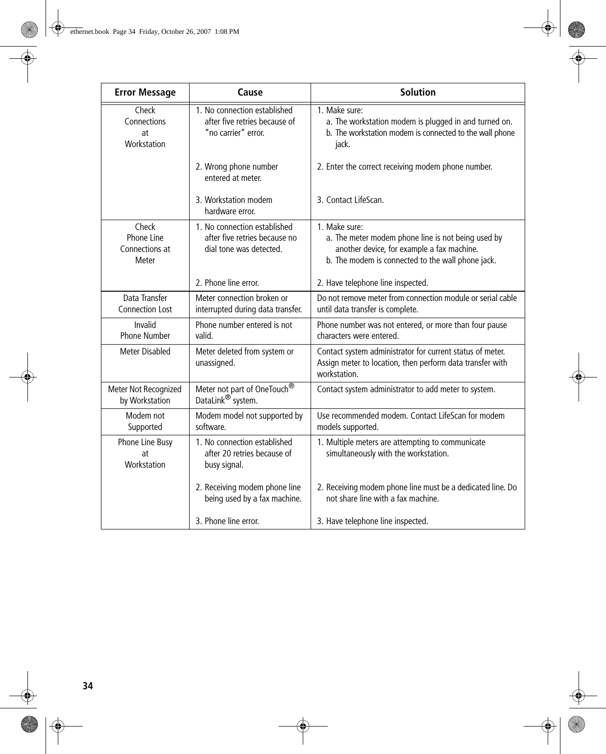
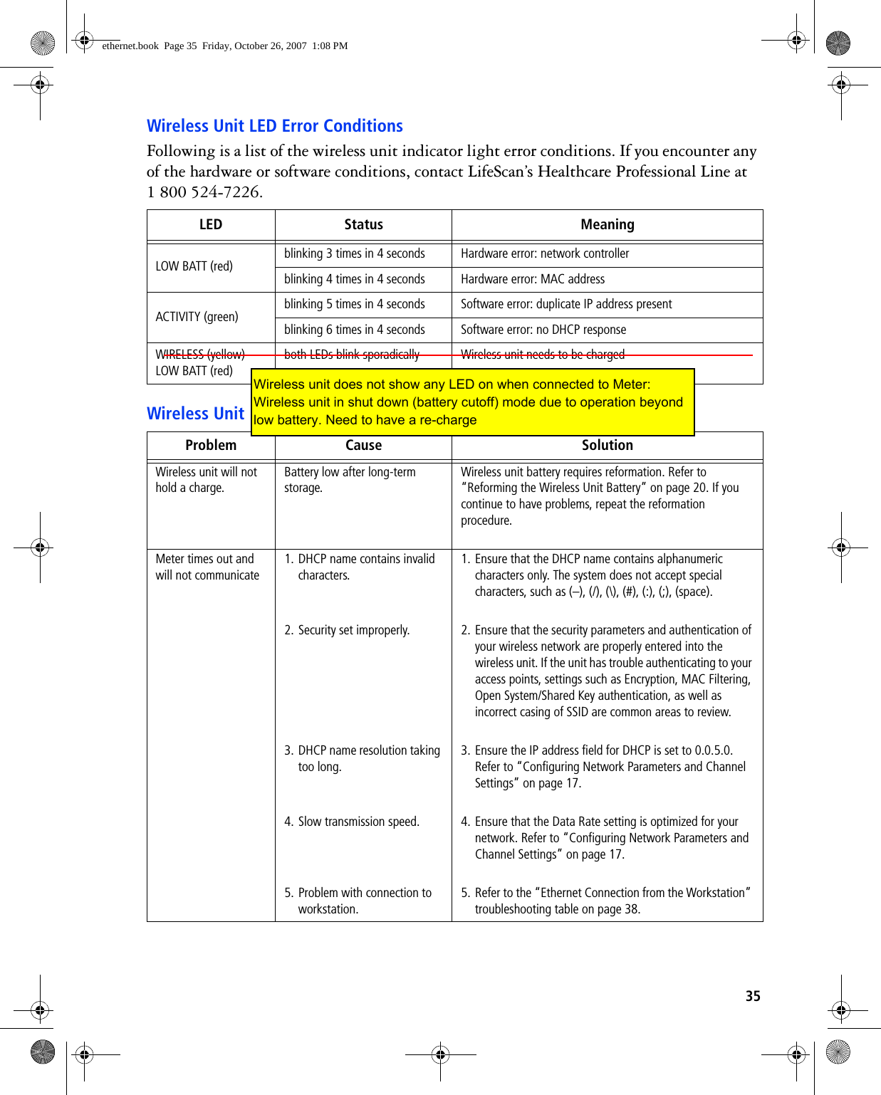
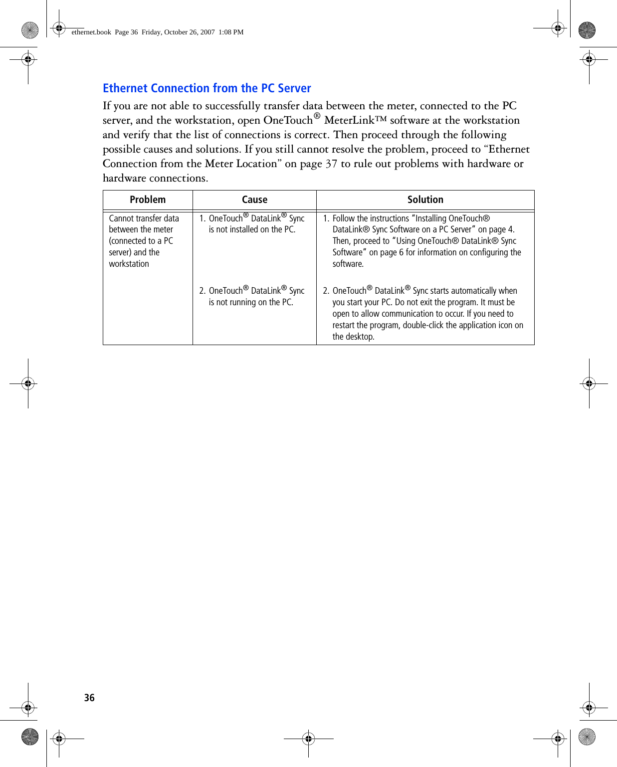
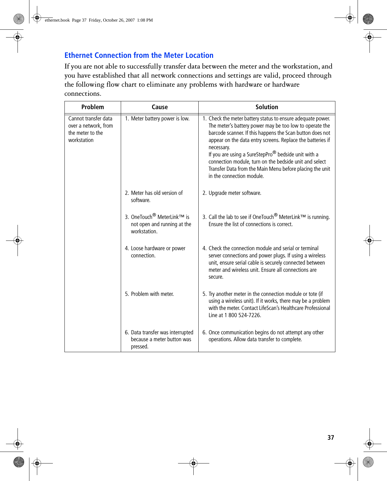
WIBATTV2 User Manual
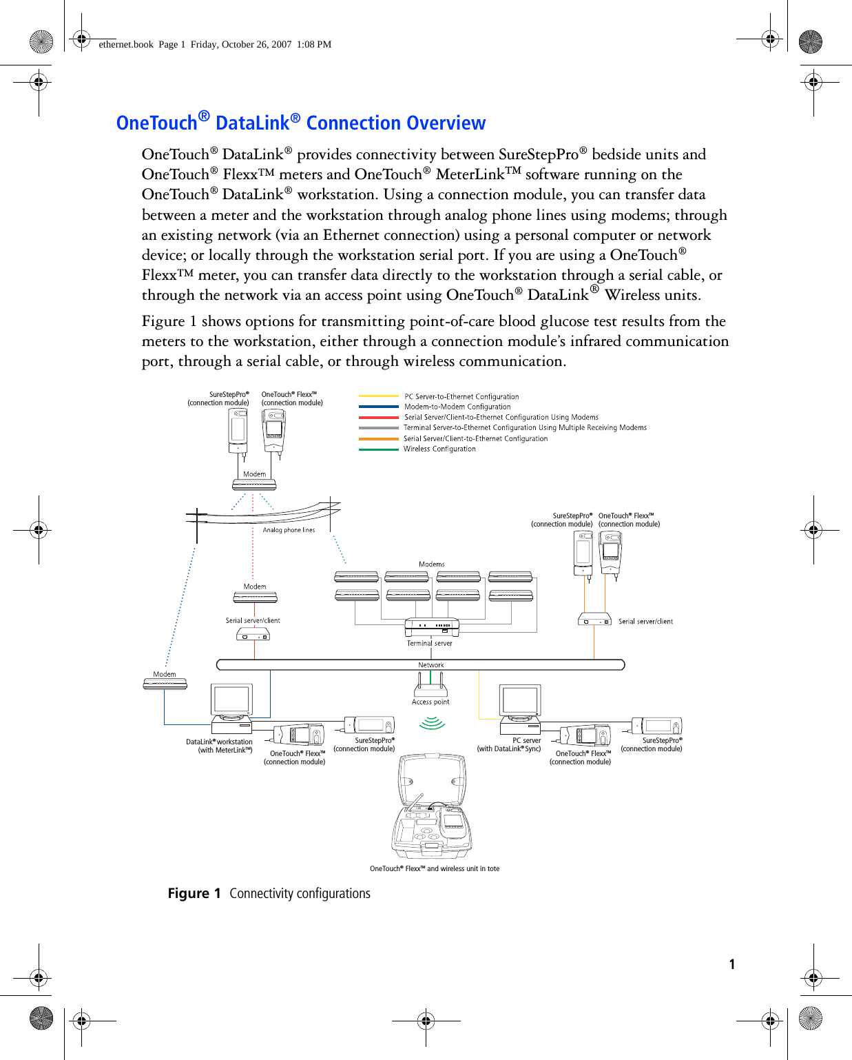
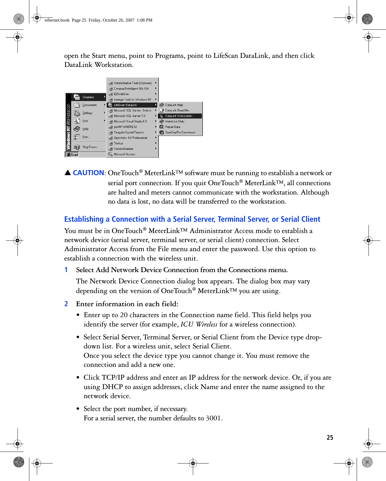
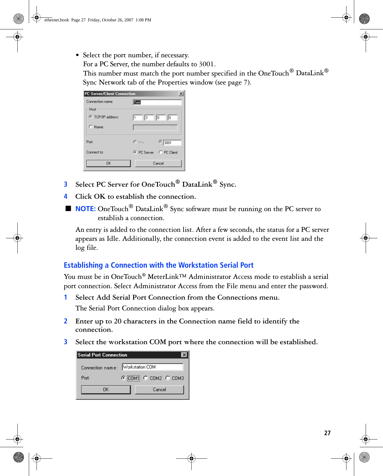
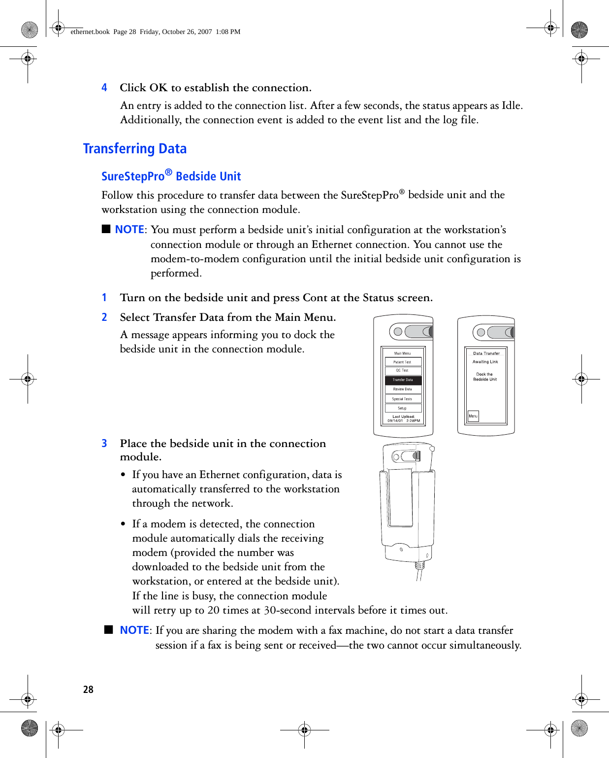
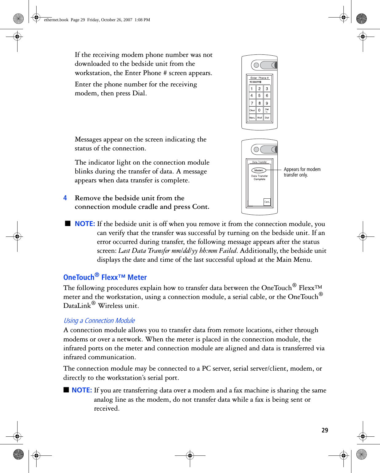
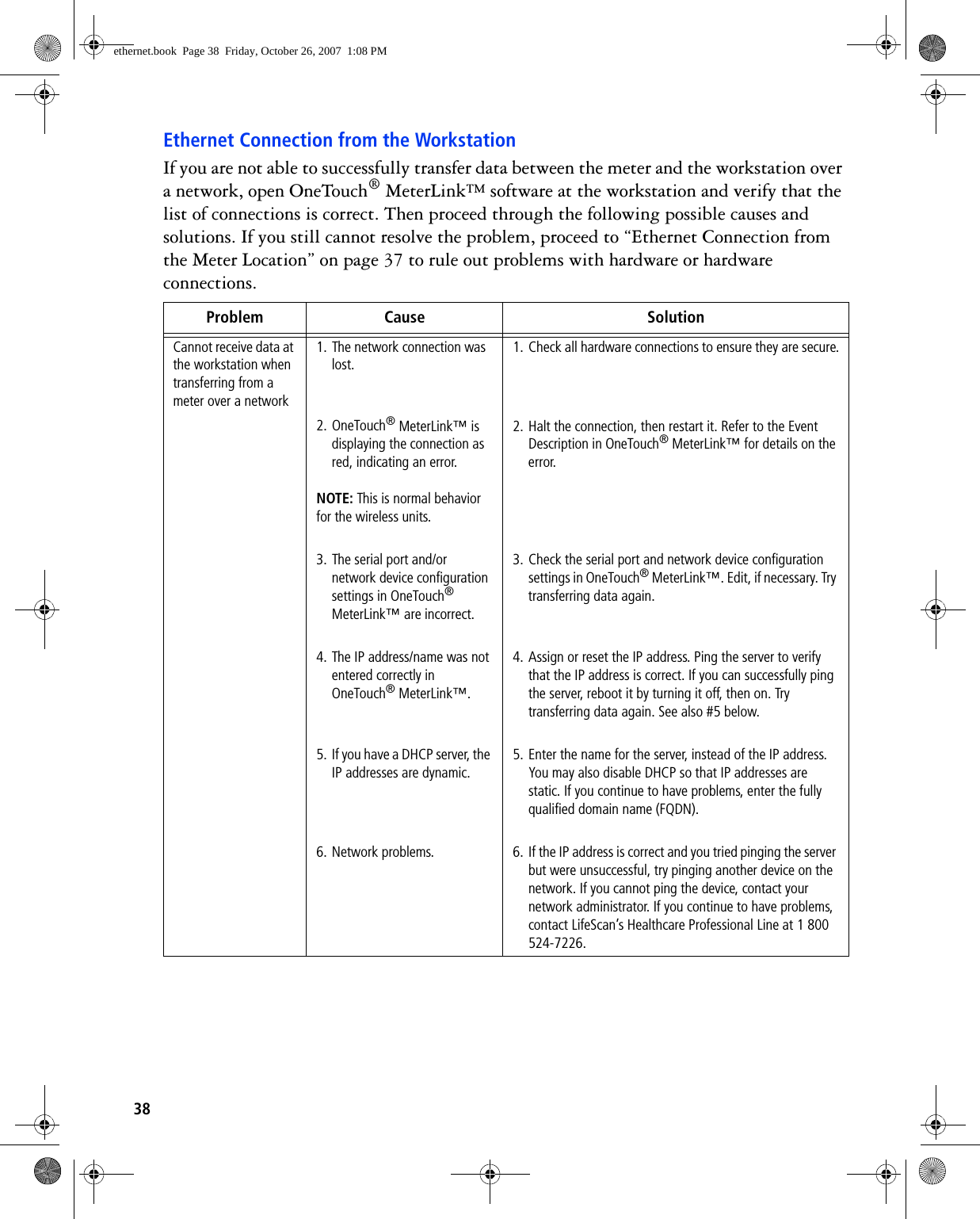
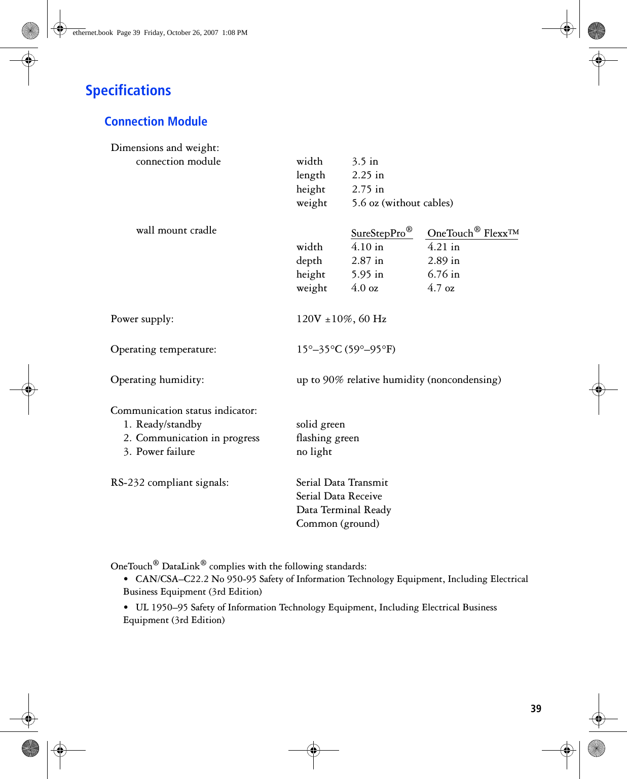
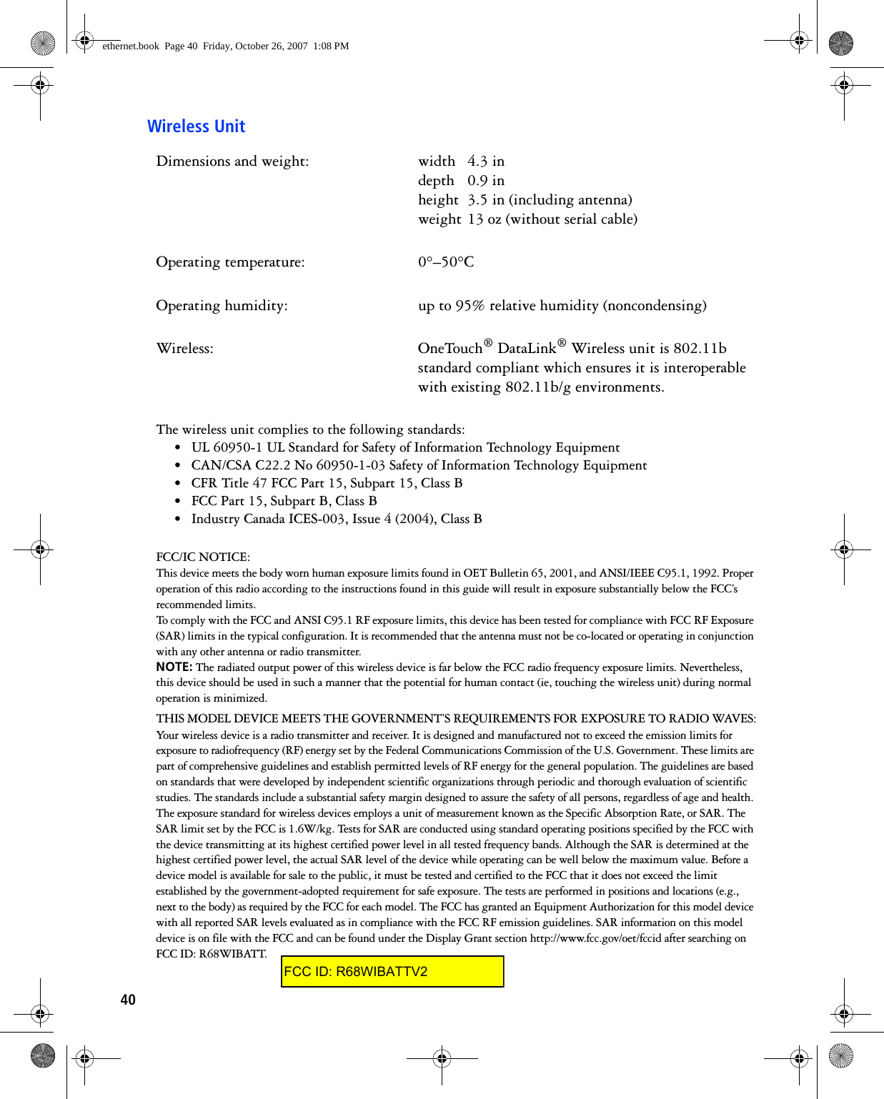
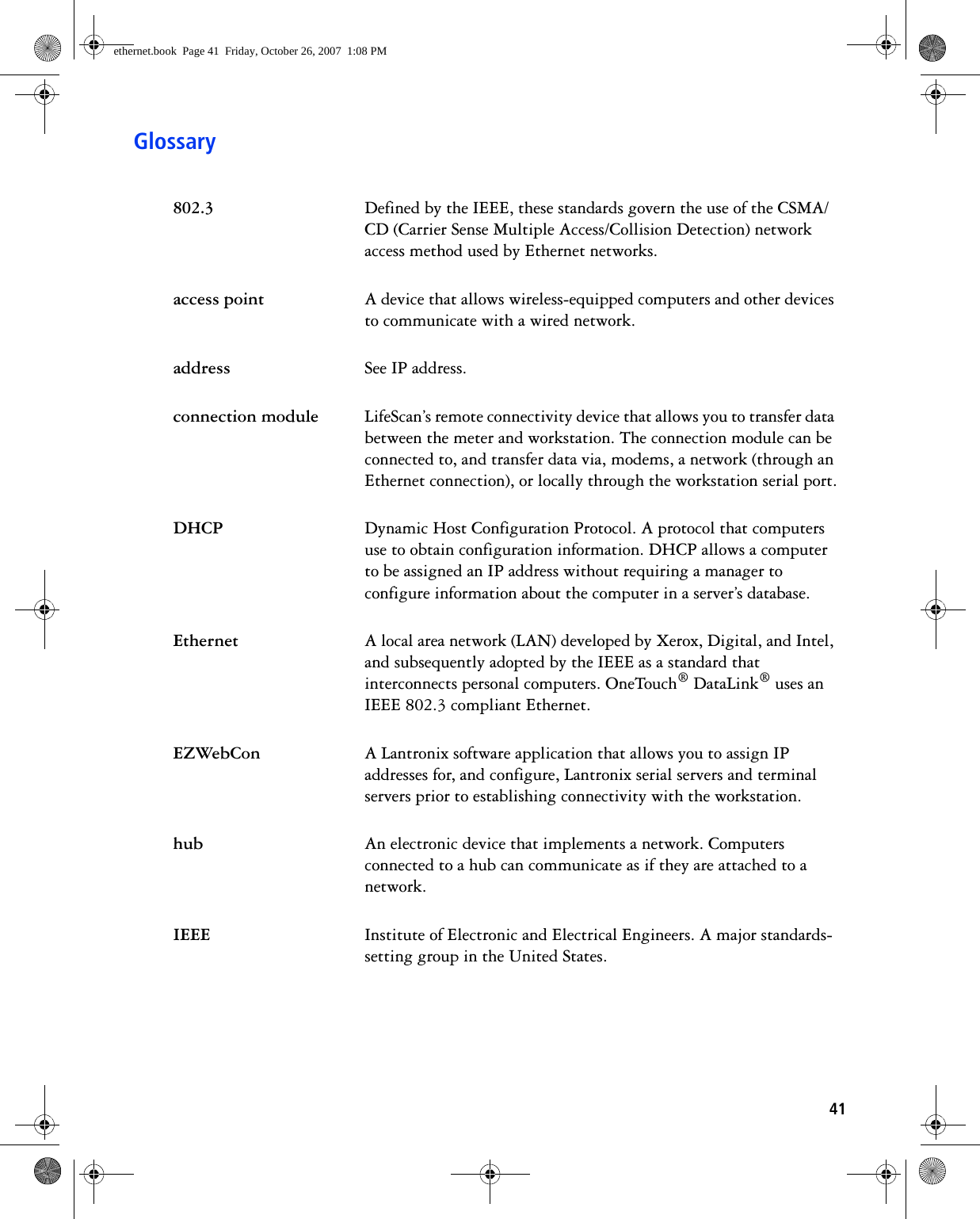
USERS MANUAL
Navigation menu
Upload a User Manual
Namespaces
Wiki Guide
HTML
PDF
Info
Views
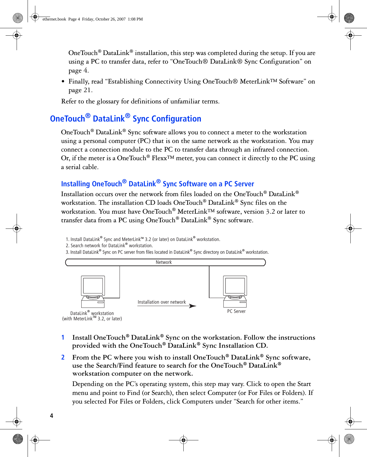
User Manual
Discussion / Help
Navigation