lantronix WIBATTV2 WIRELESS DEVICE SERVER User Manual ethernet
lantronix WIRELESS DEVICE SERVER ethernet
USERS MANUAL

OneTouch® DataLink®
Connection Guide
October 2007
ethernet.book Page 1 Friday, October 26, 2007 1:08 PM
Copyright © 2007 LifeScan, Inc. All rights reserved. No part of this publication may be
reproduced, transmitted, transcribed, stored in retrieval systems, or translated into
any language or computer language, in any form, or by any means: electronic,
mechanical, magnetic, optical, or otherwise, without the prior written permission
of LifeScan, Inc, 1000 Gibraltar Drive, Milpitas, California, 95035, United States
of America.
Disclaimer LifeScan reserves the right to change its products and services at any time to
incorporate the latest technological developments. This guide is subject to change
without notice.
Trademarks OneTouch, DataLink, and SureStepPro are registered trademarks of LifeScan, Inc.
MeterLink and Flexx are trademarks of LifeScan, Inc.
Lantronix is a registered trademark of Lantronix.
Windows is a registered trademark of Microsoft Corporation.
InstallAnywhere is a registered trademark of Zero G Software, Inc.
ethernet.book Page 2 Friday, October 26, 2007 1:08 PM
Note for Wireless Unit:
The Manufacturer is not responsible for any radio or TV interference caused by
unauthorized modifications to this equipment. Such modifications could void the user's
authority to operate the equipment
i
OneTouch® DataLink® Connection Overview . . . . . . . . . . . . . . . . . . . . . . . . . . . . . . . . . 1
Direct Connection . . . . . . . . . . . . . . . . . . . . . . . . . . . . . . . . . . . . . . . . . . . . . . . . . . . . . 2
Modem Configuration . . . . . . . . . . . . . . . . . . . . . . . . . . . . . . . . . . . . . . . . . . . . . . . . . . 2
Network Configuration . . . . . . . . . . . . . . . . . . . . . . . . . . . . . . . . . . . . . . . . . . . . . . . . . 2
Using This Guide . . . . . . . . . . . . . . . . . . . . . . . . . . . . . . . . . . . . . . . . . . . . . . . . . . . . . 3
OneTouch® DataLink® Sync Configuration . . . . . . . . . . . . . . . . . . . . . . . . . . . . . . . . . . . 4
Installing OneTouch® DataLink® Sync Software on a PC Server . . . . . . . . . . . . . . . . . . 4
Connecting a OneTouch® DataLink® Connection Module to the PC Server . . . . . . . . . 6
Using OneTouch® DataLink® Sync Software . . . . . . . . . . . . . . . . . . . . . . . . . . . . . . . . 6
Modem-to-Modem Configuration . . . . . . . . . . . . . . . . . . . . . . . . . . . . . . . . . . . . . . . . . . . . 9
Connecting a OneTouch® DataLink® Connection Module to a Sending Modem . . . . . 9
Serial Server/Client-to-Ethernet Configuration . . . . . . . . . . . . . . . . . . . . . . . . . . . . . . . . . 10
Connecting a OneTouch® DataLink® Connection Module to a Serial Server/Client . . 10
Serial Server/Client-to-Ethernet Configuration Using Modems . . . . . . . . . . . . . . . . . . . . . 11
Connecting a Receiving Modem to a Serial Server/Client . . . . . . . . . . . . . . . . . . . . . . . 12
Terminal Server-to-Ethernet Configuration Using Multiple Receiving Modems . . . . . . . . 13
Connecting a Receiving Modem to a Terminal Server . . . . . . . . . . . . . . . . . . . . . . . . . 13
Connecting to the Workstation . . . . . . . . . . . . . . . . . . . . . . . . . . . . . . . . . . . . . . . . . . . . 14
Connecting a OneTouch® DataLink® Connection Module to the Workstation . . . . . . 14
Connecting a Receiving Modem to the Workstation . . . . . . . . . . . . . . . . . . . . . . . . . . 15
Wireless Communication . . . . . . . . . . . . . . . . . . . . . . . . . . . . . . . . . . . . . . . . . . . . . . . . . 16
Setting Up the Wireless Unit . . . . . . . . . . . . . . . . . . . . . . . . . . . . . . . . . . . . . . . . . . . 16
Charging the Wireless Unit . . . . . . . . . . . . . . . . . . . . . . . . . . . . . . . . . . . . . . . . . . . . . 19
Reforming the Wireless Unit Battery . . . . . . . . . . . . . . . . . . . . . . . . . . . . . . . . . . . . . 20
Cleaning the Wireless Unit . . . . . . . . . . . . . . . . . . . . . . . . . . . . . . . . . . . . . . . . . . . . . 20
Establishing Connectivity Using OneTouch® MeterLink™ Software . . . . . . . . . . . . . . . 21
OneTouch® MeterLink™ Application Window . . . . . . . . . . . . . . . . . . . . . . . . . . . . . 21
Establishing a Connection with a Serial Server, Terminal Server, or Serial Client . . . . . 25
Establishing a Connection with a PC Server/Client . . . . . . . . . . . . . . . . . . . . . . . . . . . 26
Establishing a Connection with the Workstation Serial Port . . . . . . . . . . . . . . . . . . . . 27
Table of Contents
ethernet.book Page i Friday, October 26, 2007 1:08 PM
ii
Transferring Data . . . . . . . . . . . . . . . . . . . . . . . . . . . . . . . . . . . . . . . . . . . . . . . . . . . . . . . 28
SureStepPro® Bedside Unit . . . . . . . . . . . . . . . . . . . . . . . . . . . . . . . . . . . . . . . . . . . . . 28
OneTouch® Flexx™ Meter . . . . . . . . . . . . . . . . . . . . . . . . . . . . . . . . . . . . . . . . . . . . . 29
Troubleshooting . . . . . . . . . . . . . . . . . . . . . . . . . . . . . . . . . . . . . . . . . . . . . . . . . . . . . . . . 33
OneTouch® MeterLink™ Event Errors . . . . . . . . . . . . . . . . . . . . . . . . . . . . . . . . . . . . 33
Meter Error Messages . . . . . . . . . . . . . . . . . . . . . . . . . . . . . . . . . . . . . . . . . . . . . . . . . 33
Wireless Unit LED Error Conditions . . . . . . . . . . . . . . . . . . . . . . . . . . . . . . . . . . . . . . 35
Wireless Unit . . . . . . . . . . . . . . . . . . . . . . . . . . . . . . . . . . . . . . . . . . . . . . . . . . . . . . . 35
Ethernet Connection from the PC Server . . . . . . . . . . . . . . . . . . . . . . . . . . . . . . . . . . . 36
Ethernet Connection from the Meter Location . . . . . . . . . . . . . . . . . . . . . . . . . . . . . . . 37
Ethernet Connection from the Workstation . . . . . . . . . . . . . . . . . . . . . . . . . . . . . . . . . 38
Specifications . . . . . . . . . . . . . . . . . . . . . . . . . . . . . . . . . . . . . . . . . . . . . . . . . . . . . . . . . . 39
Connection Module . . . . . . . . . . . . . . . . . . . . . . . . . . . . . . . . . . . . . . . . . . . . . . . . . . . 39
Wireless Unit . . . . . . . . . . . . . . . . . . . . . . . . . . . . . . . . . . . . . . . . . . . . . . . . . . . . . . . 40
Glossary . . . . . . . . . . . . . . . . . . . . . . . . . . . . . . . . . . . . . . . . . . . . . . . . . . . . . . . . . . . . . . 41
Index . . . . . . . . . . . . . . . . . . . . . . . . . . . . . . . . . . . . . . . . . . . . . . . . . . . . . . . . . . . . . . . . 45
ethernet.book Page ii Friday, October 26, 2007 1:08 PM
1
OneTouch® DataLink® Connection Overview
OneTouch® DataLink® provides connectivity between SureStepPro® bedside units and
OneTouch® Flexx™ meters and OneTouch® MeterLinkTM software running on the
OneTouch® DataLink® workstation. Using a connection module, you can transfer data
between a meter and the workstation through analog phone lines using modems; through
an existing network (via an Ethernet connection) using a personal computer or network
device; or locally through the workstation serial port. If you are using a OneTouch®
Flexx™ meter, you can transfer data directly to the workstation through a serial cable, or
through the network via an access point using OneTouch® DataLink® Wireless units.
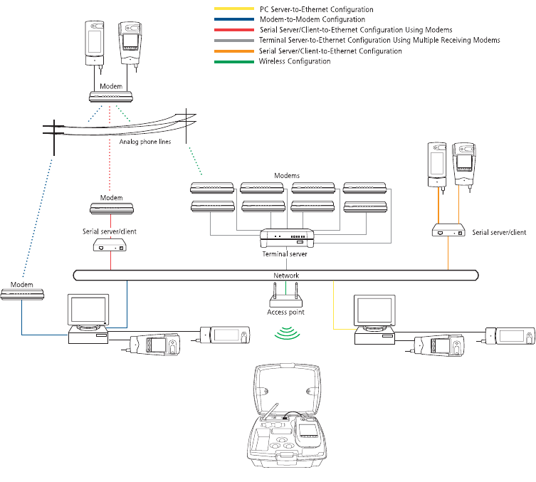
Figure 1 shows options for transmitting point-of-care blood glucose test results from the
meters to the workstation, either through a connection module’s infrared communication
port, through a serial cable, or through wireless communication.
Figure 1 Connectivity configurations
SureStepPro
®
(connection module)
OneTouch
®
Flexx
TM
(connection module)
SureStepPro
®
(connection module)
OneTouch
®
Flexx
TM
(connection module)
PC server
(with DataLink
®
Sync) OneTouch
®
Flexx
TM
(connection module)
SureStepPro
®
(connection module)
OneTouch
®
Flexx
TM
and wireless unit in tote
DataLink
®
workstation
(with MeterLink
TM
)OneTouch
®
Flexx
TM
(connection module)
SureStepPro
®
(connection module)
ethernet.book Page 1 Friday, October 26, 2007 1:08 PM
2
Because there are numerous configuration possibilities and each network is unique,
LifeScan recommends you consult with a LifeScan representative for an assessment of your
institution’s connectivity capabilities and needs.
■NOTE: Consult with your network administrator prior to installing any devices on the
network.
Direct Connection
You may connect either the SureStepPro® or the OneTouch® Flexx™ meter directly to the
workstation using a connection module. If you are using a OneTouch® Flexx™ meter, you
can connect to the workstation using the OneTouch® DataLink® serial cable.
Requirements for Direct Connection
• OneTouch® DataLink® system software, version 3.2 or later
• OneTouch® MeterLink™ software, version 3.0 or later
• OneTouch® DataLink® serial cable (for OneTouch® Flexx™ meter only); or connection
module, serial port connector, and phone cable
Modem Configuration
Data from the meter can be transferred from a sending modem through standard analog
phone lines to a receiving modem. To utilize an existing network, receiving modems can
be connected to a network device, which connects to the network through an Ethernet
connection. See “Network Configuration” below.
Requirements for Modem Configuration
• OneTouch® DataLink® system software, version 3.2 or later
• OneTouch® MeterLink™ software, version 3.0 or later
• OneTouch® DataLink® connection module and/or cradle
• Modems
• Analog phone lines
• Serial modem cable (for receiving modem/workstation connection)
• Modem connector and phone cable (for sending modem/connection module connection)
Network Configuration
There are several configuration options available if you have an existing network. By using
a standard personal computer (PC) connected to a network and running OneTouch®
DataLink® Sync software, you can transfer data from a meter to the workstation through
the PC. You may also use a serial server or serial client to connect a meter to the
workstation through the network. The serial server/client links the meter or a sending
modem to the network. If you are using modems with a network configuration, you can
connect one receiving modem to a serial server/client and up to eight receiving modems to
ethernet.book Page 2 Friday, October 26, 2007 1:08 PM
3
one terminal server. If you are using a wireless configuration, the serial client becomes the
OneTouch® DataLink® Wireless unit, which transmits data through the network via an
access point.
Requirements for Network Configuration
• OneTouch® DataLink® system software, version 3.2 or later
• OneTouch® MeterLink™ software, version 3.0 or later (version 3.2 or later for
OneTouch® DataLink® Sync configuration; version 3.3 or later for serial client network
devices and wireless configuration)
• OneTouch® DataLink® serial cable or cradle (for OneTouch® Flexx™ meter only); or
connection module, serial port connector, and phone cable
• Network connection supporting Ethernet IEEE 802.3 protocol
• Point-to-point connections across workstation and network device subnets
• TCP/IP protocol and services
Additional Requirements for OneTouch
®
DataLink
®
Sync Configuration
• OneTouch® DataLink® Sync software running on the PC
• Personal computer (PC) that is networked to the workstation and has: 300 MHz or
greater processor; 800 x 600, 256-color monitor; 50 MB free hard disk space; Windows
98 second edition, Windows NT, 2000, or XP operating system; minimum RAM
required by operating system; available RS-232 serial port for connection to a meter
■NOTE: A serial-to-USB adapter may be used if an RS-232, 9-pin serial port is not
available. LifeScan does not provide or recommend any serial-to-USB adapters.
Additional Requirements for Network Device Configuration
Contact LifeScan for a list of supported hardware and corresponding configuration
parameters for all network device connectivity options.
■NOTE: Connectors and/or hardware configurations for serial clients may be different
than for serial servers. Contact LifeScan for information on connecting serial
clients to the network.
Using This Guide
This guide outlines several connection configurations and provides instructions for
installing the components and transferring data.
After identifying the appropriate configuration setup:
• Refer to the specific section of this guide to connect the hardware components. The
numbered steps in the instructions correspond to the numbers in the connection figure.
• Then, if you are using a network configuration with network devices, assign IP
addresses and configure the devices. If LifeScan assisted you with your initial
ethernet.book Page 3 Friday, October 26, 2007 1:08 PM
4
OneTouch® DataLink® installation, this step was completed during the setup. If you are
using a PC to transfer data, refer to “OneTouch® DataLink® Sync Configuration” on
page 4.
• Finally, read “Establishing Connectivity Using OneTouch® MeterLink™ Software” on
page 21.
Refer to the glossary for definitions of unfamiliar terms.
OneTouch® DataLink® Sync Configuration
OneTouch® DataLink® Sync software allows you to connect a meter to the workstation
using a personal computer (PC) that is on the same network as the workstation. You may
connect a connection module to the PC to transfer data through an infrared connection.
Or, if the meter is a OneTouch® Flexx™ meter, you can connect it directly to the PC using
a serial cable.
Installing OneTouch® DataLink® Sync Software on a PC Server
Installation occurs over the network from files loaded on the OneTouch® DataLink®
workstation. The installation CD loads OneTouch® DataLink® Sync files on the
workstation. You must have OneTouch® MeterLink™ software, version 3.2 or later to
transfer data from a PC using OneTouch® DataLink® Sync software.
1Install OneTouch® DataLink® Sync on the workstation. Follow the instructions
provided with the OneTouch® DataLink® Sync Installation CD.
2From the PC where you wish to install OneTouch® DataLink® Sync software,
use the Search/Find feature to search for the OneTouch® DataLink®
workstation computer on the network.
Depending on the PC’s operating system, this step may vary. Click to open the Start
menu and point to Find (or Search), then select Computer (or For Files or Folders). If
you selected For Files or Folders, click Computers under “Search for other items.”
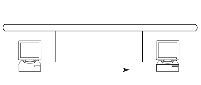
1. Install DataLink® Sync and MeterLinkTM 3.2 (or later) on DataLink® workstation.
2. Search network for DataLink® workstation.
3. Install DataLink® Sync on PC server from files located in DataLink® Sync directory on DataLink® workstation.
DataLink® workstation
(with MeterLinkTM 3.2, or later)
Installation over network
PC Server
Network
ethernet.book Page 4 Friday, October 26, 2007 1:08 PM
5
3Enter the name of the OneTouch® DataLink® workstation. The default name
should be LFS_DATALINK or LFS-DATALINK.
4Locate and open the DataLink Sync directory on the C drive.
5Double-click install.htm.
The browser launches and a window appears prompting you to install and run
“InstallAnywhere Web Installer.” Click Yes or Grant to accept—the button may vary
depending on your browser.
6Click Start Installer for Windows.
The Download Progress screen appears followed by the InstallAnywhere screen.
7Click Next in the Introduction window.
8Click Install to install OneTouch® DataLink® Sync software in the default
directory (C:/Program Files/LifeScan/DataLink Sync). Or, if you wish to install
the program in another location, click Choose and select a new directory.
The installer creates three shortcuts to OneTouch® DataLink® Sync:
• in the Programs folder
• on the desktop
• in the Startup folder
9Click Done in the Install Complete window.
You may now proceed to configuring OneTouch® DataLink® Sync. Refer to
“Configuring OneTouch® DataLink® Sync Software” starting on page 6.
10 Close the browser window.
■NOTE: If you suspect that the installation was not successful, for example, a
OneTouch® DataLink® Sync shortcut does not appear on the desktop after
installation, you may not have the correct log-in privileges for the PC. Contact
your system administrator for assistance.
ethernet.book Page 5 Friday, October 26, 2007 1:08 PM
6
Connecting a OneTouch® DataLink® Connection Module to the PC Server
The procedure for connecting a connection module or a serial cable to the PC server is the
same as connecting to the workstation. Follow the instructions under “Connecting a
OneTouch® DataLink® Connection Module to the Workstation” on page 14 to connect a
connection module or serial cable to the PC server.
Using OneTouch® DataLink® Sync Software
Configuring OneTouch
®
DataLink
®
Sync Software
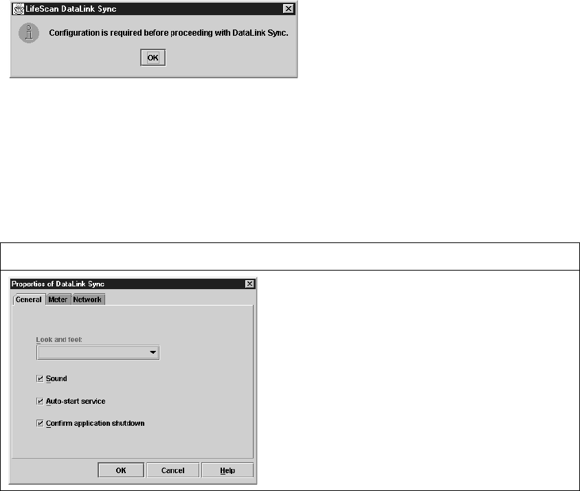
The first time you launch the program after you install it, the following dialog box
appears. If you restart your computer after installing OneTouch® DataLink® Sync
software, this dialog box appears after the computer starts.
1Click OK.
The properties window appears.
2Refer to the descriptions for each Properties tab field listed in the table below.
The Properties window allows you to set certain software features and select the meter
type and COM port used for data transfer. The table on page 6 includes information on
the General, Meter, and Network tabs. Options at the General tab do not need to be
configured for OneTouch® DataLink® Sync software to function correctly.
DataLink® Sync Properties Tabs Description
Look and feel
Select the appearance of the application. Choose between Metal or
Windows.
Sound
A sound is emitted at the start of a data transfer session.
Auto-start service
Opens a connection between the workstation and the PC for data
transfer when a meter is connected. OneTouch® DataLink® Sync
software starts minimized when this option is selected.
Confirm application shutdown
Always displays a confirmation dialog when you attempt to exit the
application.
ethernet.book Page 6 Friday, October 26, 2007 1:08 PM
7
OneTouch
®
DataLink
®
Sync Software Main Screen
OneTouch® DataLink® Sync software starts automatically when you turn on the PC. If
you do not want the program to launch automatically, you can remove the OneTouch®
DataLink® Sync shortcut from the Startup folder. Then, to start the program double-click
the OneTouch® DataLink® Sync icon on the desktop. Or, click Start, point to Programs,
then click LifeScan DataLink Sync.
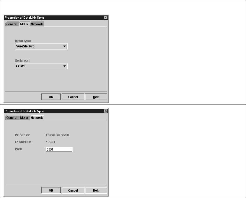
Meter type
Allows you to select the meter type used in the data transfer session.
If the meter is OneTouch® Flexx™, select SureStepFlexx (Direct) for
a serial cable connection, or SureStepFlexx (Infrared) for a
connection module connection. Select SureStepPro if you are
connecting a SureStepPro® bedside unit.
Serial port
Allows you to select the serial port used for data transfer. You may
connect a connection module (for OneTouch® Flexx™ and
SureStepPro®) or a serial cable (for OneTouch® Flexx™) to the
serial port.
PC server
The name assigned to the PC server.
IP address
The IP address of the PC server.
Port
The TCP/IP port number for the PC server (1024 to 65535). This
number must match the port number assigned to the PC server in
OneTouch® MeterLink™ software at the workstation (see step 2 on
page 26). The default is 3001.
DataLink® Sync Properties Tabs Description
ethernet.book Page 7 Friday, October 26, 2007 1:08 PM
8
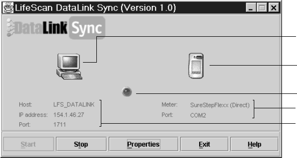
■IMPORTANT: The program must be open to allow communications to occur.
Figure 2 OneTouch® DataLink® Sync software main screen showing active connection with the workstation
•Start – opens a connection to the workstation (Host) allowing for data transfer when a
meter is connected.
•Stop – closes the connection between the workstation and the PC server.
•Properties – displays the Properties window allowing you to customize certain
OneTouch® DataLink® Sync software features.
•Exit – closes the program.
•Help – displays the online Help window.
■NOTE: OneTouch® MeterLink™ software regularly opens and closes the connection to
OneTouch® DataLink® Sync to ensure a valid connection. The workstation icon
and Host, IP address, and Port fields toggle between an active connection and
no connection when no communication with a meter is occurring. You will
notice the Port number changing with each established connection.
Transferring Data Using OneTouch
®
DataLink
®
Sync
Before using OneTouch® DataLink® Sync software to transfer data from the meter to the
workstation, you must install OneTouch® DataLink® Sync software on the PC server,
configure the settings, and connect a meter to the PC using either a connection module or
a serial cable. See page 4 for installation instructions, page 6 for information on
configuring OneTouch® DataLink® Sync, and page 6 for connection instructions.
1Place the meter in the connection module. Or, connect the OneTouch® Flexx™
meter to the PC using a serial cable.
You can connect a connection module to the PC for transferring data from a
SureStepPro® or OneTouch® Flexx™ meter. Or, you can connect a OneTouch®
DataLink® serial cable (or the serial cable in the connection module cradle) to the PC
Flashes during data transfer session.
OneTouch® DataLink® workstation
information. Appears when OneTouch®
MeterLink™ at workstation is actively
connected to OneTouch® DataLink®
Sync on PC server.
Displays type of meter used for transfer.
Select meter in Meter tab of Properties
window.
PC server configuration information.
Indicates status of connection between
workstation and OneTouch® DataLink®
Sync.
ethernet.book Page 8 Friday, October 26, 2007 1:08 PM

9
for transferring data from a OneTouch® Flexx™ meter. For more information on
transferring data from the meter, refer to “Transferring Data” on page 28.
If Auto-start service is selected in the General tab of the Properties window, data
transfer occurs automatically when you connect the meter. If Auto-start service is not
selected, you must click Start to begin data transfer.
■NOTE: The Start button simply opens a connection between the PC and the
workstation. It does not initiate communications. Therefore, the order in
which you connect and click Start is not critical (for example, you may
click Start, then connect the meter).
Modem-to-Modem Configuration
Modems can be used to connect a meter to the workstation through an analog phone line.
Connect a sending modem to the connection module and a receiving modem to the
workstation.
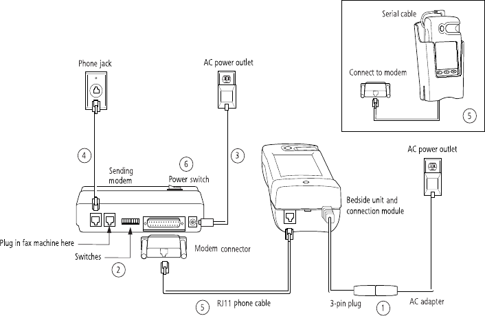
Connecting a OneTouch® DataLink® Connection Module to a Sending Modem
Follow this procedure to connect a sending modem to a connection module (see Figure 3).
If you have a OneTouch® Flexx™ meter, you can connect the meter to the modem with
the serial cable located in the cradle. For instructions on connecting a receiving modem to
the workstation, refer to page 15.
1Connect the 3-pin plug of the connection module power cord to the receptacle
on the AC adapter. Then, plug the AC adapter into an AC power outlet.
Make sure the green indicator light on the connection module is on.
2Set the switches on the back of the modem as follows:
3Connect the power cord from the modem to an AC power outlet.
4Connect a phone cable from the modem to an analog phone jack.
■NOTE: The modem’s jack is labeled with a wall plug icon on the bottom of the modem.
If you currently have a fax machine or analog phone plugged into the wall jack, you
may plug the fax/phone cable directly into the other jack on the modem (see Figure 3).
This jack is labeled with a phone icon on the bottom of the modem.
5Connect a phone cable from the connection module to the modem connector.
Then, connect the modem connector to the modem.
If the meter is a OneTouch® Flexx™, you may connect the serial cable in the
cradle to the meter. Connect a phone cable from the cradle to the modem
12345678
up up down up down up down down
ethernet.book Page 9 Friday, October 26, 2007 1:08 PM
10
connector. Then, connect the modem connector to the modem (as shown in
inset).
▲WARNING: Connect the phone cable to the modem connector only. Failure to do so
could result in electrical shock.
6Turn on the modem.
Figure 3 Modem-to-connection module (or meter) connection
Serial Server/Client-to-Ethernet Configuration
A serial server or serial client allows you to connect a connection module to the workstation
through your network’s Ethernet connection. One serial server/client is required for each
connection module. For wireless communication, a wireless unit (serial client) transmits
data to an access point installed on your network. The serial server/client must be
configured prior to use. Refer to the appropriate document for configuration information.
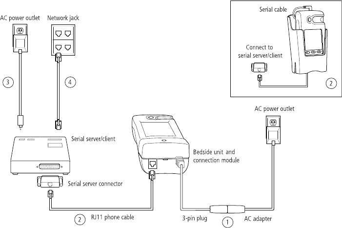
Connecting a OneTouch® DataLink® Connection Module to a Serial Server/Client
Follow this procedure to connect a serial server/client to a connection module (see
Figure 4). If you have a OneTouch® Flexx™ meter, you can connect the meter to the serial
server/client with the serial cable located in the cradle.
1Connect the 3-pin plug of the connection module power cord to the receptacle
on the AC adapter. Then, plug the AC adapter into an AC power outlet.
Make sure the green indicator light on the connection module is on.
ethernet.book Page 10 Friday, October 26, 2007 1:08 PM
11
2Connect a phone cable between the connection module and the serial server
connector. Then, connect the serial server connector to the serial server/client.
If the meter is a OneTouch® Flexx™ meter, you may connect the serial cable in
the cradle to the meter. Connect a phone cable from the cradle to the serial
server connector. Then, connect the serial server connector to the serial server/
client (as shown in inset).
▲WARNING: Connect the phone cable to the serial server connector only. Failure to do
so could result in electrical shock.
3Connect the power cord from the serial server/client to an AC power outlet.
4Connect the network patch cable from the serial server/client to the network jack
or hub.
Figure 4 Serial server/client-to-connection module connection
Serial Server/Client-to-Ethernet Configuration Using Modems
Using a serial server or serial client with a modem configuration allows you to incorporate
an existing modem configuration into a network. Additionally, if you are using a serial
server/client-to-Ethernet configuration and have a remote site(s) that communicates with
the parent institution via modem, a serial server/client connected to the receiving modem
allows you to transmit data from the remote site to the institution’s network. The serial
server/client must be configured prior to use. Refer to the appropriate document for
configuration information.
ethernet.book Page 11 Friday, October 26, 2007 1:08 PM
12
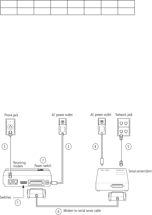
Connecting a Receiving Modem to a Serial Server/Client
Follow this procedure to connect a receiving modem to a serial server/client (see Figure 5).
For instructions on connecting a sending modem to a connection module, refer to page 9.
1Set the switches on the back of the modem as follows:
2Connect the power cord from the modem to an AC power outlet.
3Connect a phone cable from the modem to an analog phone jack. The jack must
be for a dedicated analog phone line.
■NOTE: The modem’s jack is labeled with a wall plug icon on the bottom of the modem.
4Connect the power cord from the serial server/client to an AC power outlet.
5Connect the network patch cable from the serial server/client to the network jack
or hub.
6Connect the modem-to-serial server cable between the serial server/client and
modem.
7Turn on the modem.
Figure 5 Modem-to-serial server/client connection
12345678
down up up down up up down up
ethernet.book Page 12 Friday, October 26, 2007 1:08 PM
13
Terminal Server-to-Ethernet Configuration Using Multiple Receiving Modems
A terminal server may be used to connect multiple (up to eight) receiving modems to an
existing network through an Ethernet connection. The terminal server must be configured
prior to use. Refer to the appropriate document for configuration information.
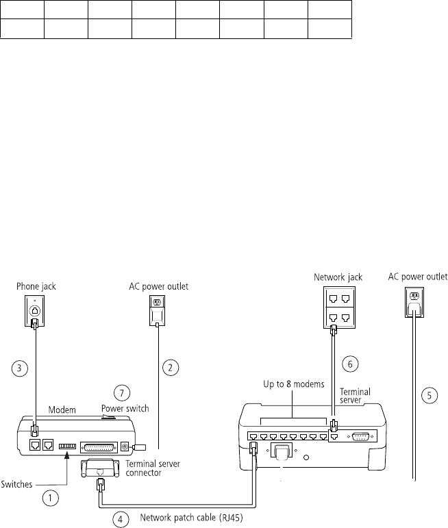
Connecting a Receiving Modem to a Terminal Server
Follow this procedure to connect up to eight receiving modems to a terminal server
(see Figure 6). For instructions on connecting a sending modem to a connection module,
refer to page 9.
1Set the switches on the back of the modem as follows:
2Connect the power cord from the modem to an AC power outlet.
3Connect a phone cable from the modem to an analog phone jack. The jack must
be for a dedicated analog phone line.
■NOTE: The modem’s jack is labeled with a wall plug icon on the bottom of the modem.
4Connect the network patch cable from the terminal server to the terminal
server connector. Then, connect the terminal server connector to the modem.
5Connect the power cord from the terminal server to an AC power outlet.
6Connect the network patch cable from the terminal server to the network jack or hub.
7Turn on the modem and terminal server.
Figure 6 Modem-to-terminal server connection
12345678
down up up down up up down up
ethernet.book Page 13 Friday, October 26, 2007 1:08 PM

14
Connecting to the Workstation
Workstation connections will vary depending on the configurations option you choose. See
Figure 1 for connection options.
Connecting a OneTouch® DataLink® Connection Module to the Workstation
Follow this procedure to connect a connection module to the workstation (see Figure 7). If
you have a OneTouch® Flexx™ meter, you can connect the meter directly to the
workstation using the OneTouch® DataLink® serial cable or the serial cable in the cradle.
Turn off the workstation before making any connections.
1Connect the 3-pin plug of the connection module power cord to the receptacle
on the AC adapter. Then, plug the AC adapter into an AC power outlet.
If you’re connecting a OneTouch® Flexx™ meter to the workstation using a
serial cable, skip this step.
Make sure the green indicator light on the connection module is on.
2Connect a phone cable from the connection module to the serial port connector.
Then, connect the serial port connector to the workstation’s serial port.
If you’re connecting a OneTouch® Flexx™ meter to the workstation, you may
connect the serial cable (either the OneTouch® DataLink® serial cable or the
serial cable in the cradle) between the meter and the workstation (as shown in
insets).
▲WARNING: Connect the phone cable to the serial port connector only. Failure to do so
could result in electrical shock.
3If applicable, connect the network patch cable from the workstation to the
network jack.
4Turn on the workstation.
ethernet.book Page 14 Friday, October 26, 2007 1:08 PM
15
Figure 7 Connection module-to-workstation connection
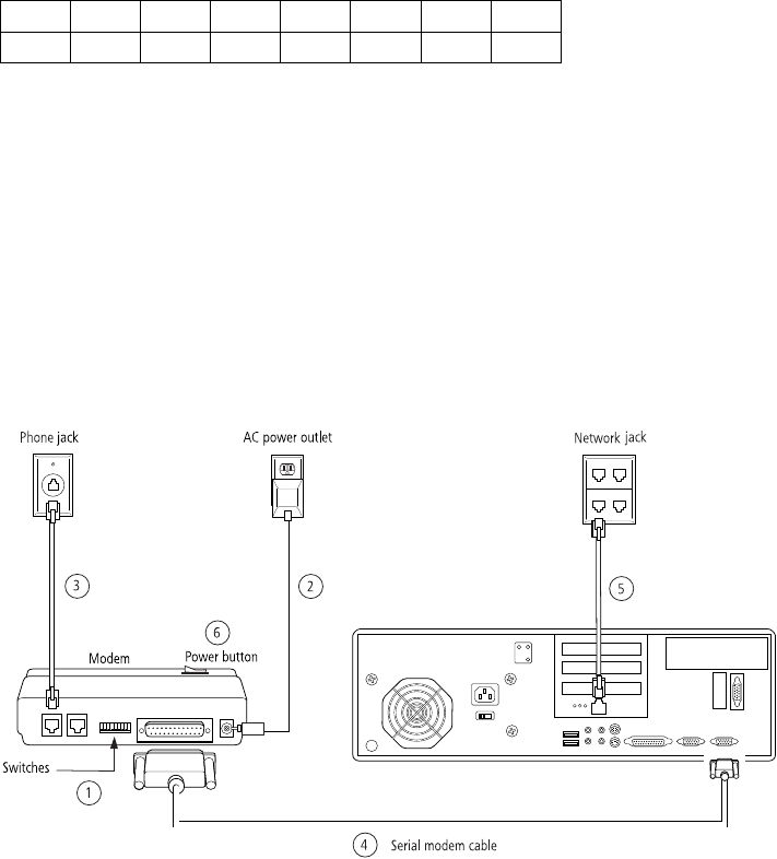
Connecting a Receiving Modem to the Workstation
Follow this procedure to connect a receiving modem to the workstation (see Figure 8).
1Set the switches on the back of the modem as follows:
2Connect the power cord from the modem to an AC power outlet.
3Connect a phone cable from the modem to an analog phone jack. The phone
jack must be for a dedicated analog phone line.
■NOTE: The modem’s jack is labeled with a wall plug icon on the bottom of the modem.
4Connect the serial modem cable from the modem to the serial port on the
workstation.
5If applicable, connect the network patch cable from the workstation to the
network jack.
6Turn on the modem and workstation.
Figure 8 Modem-to-workstation connection
12345678
down up up down up up down up
ethernet.book Page 15 Friday, October 26, 2007 1:08 PM
16
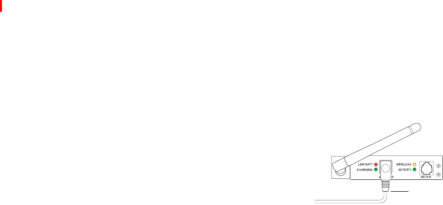
Wireless Communication
The OneTouch® DataLink® Wireless unit allows you to
transfer data from a OneTouch® Flexx™ meter to the
workstation via a network enabled through wireless
access. The meter plugs into a wireless unit located in the
meter tote. Data is transmitted through access points
installed on the network.
■NOTE: If you need to reload the wireless unit’s
firmware, or in the event of an upgrade,
LifeScan will assist you with obtaining
the correct version, as well as installation instructions.
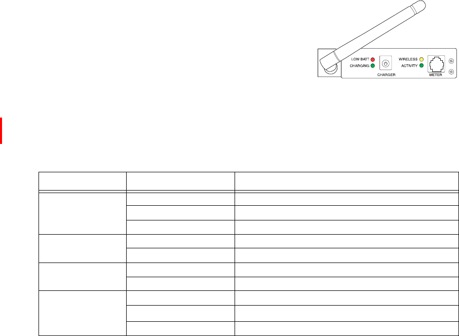
The following table provides a description of the LEDs found on the wireless unit.
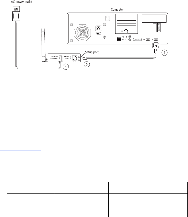
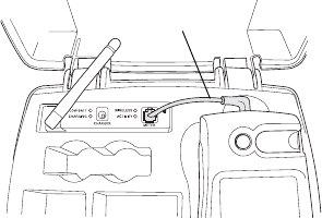
Setting Up the Wireless Unit
You must set up and configure the wireless unit before using it to transfer data. Units can
be configured from any computer. Charge the wireless unit before setting it up.
1Connect a phone cable to the serial port connector. Then, connect the serial
port connector to the workstation’s serial port.
2Open a HyperTerminal session in Windows.
3Click Restore Defaults on the Port Settings screen. The COM properties for the
port should be:
• Bits Per Second = 9600
• Data Bits = 8
• Parity = None
• Stop Bits = 1
LED Status Meaning
LOW BATT (red)
steady approximately 10% of battery capacity remaining (~20 minutes)
off sufficiently charged
blinking hardware error detected, see error table on page 35
CHARGING (green) steady fast charge is complete
blinking unit is fast charging
WIRELESS (yellow) steady wireless connection established
blinking searching for wireless connection
ACTIVITY (green)
steady active TCP (OneTouch® MeterLink™) connection
off no TCP (OneTouch® MeterLink™) connection
blinking software error detected, see error table on page 35
OneTouch® DataLink® Wireless unit
ethernet.book Page 16 Friday, October 26, 2007 1:08 PM
17
• Flow Control = None
4Connect the charger to the wireless unit. Then, plug the charger into an
AC power outlet.
5While holding down the X key on the keyboard (ensure Caps Lock is off),
connect the other end of the phone cable (from step 1) to the Setup jack on the
side of the wireless unit.
6Press Enter when prompted.
Figure 9 Setting up the OneTouch® DataLink® Wireless unit
Configuring Network Parameters and Channel Settings
Perform the following steps with the wireless unit still connected to the computer.
1From the Change Setup menu, select option 0 and press Enter.
2Continue with the appropriate instructions below depending on whether you
are using static IP addresses or DHCP.
For a Static IP
• Enter the IP address for the wireless unit.
• Enter the Gateway IP address.
• Define the Netmask: Number of Bits for Host Port.
• Change the default Telnet password, if you wish.
Network Class Host Bits Netmask
A 24 255.0.0.0
B 16 255.255.0.0
C 8 255.255.255.0
ethernet.book Page 17 Friday, October 26, 2007 1:08 PM

18
For DHCP
• Enter 0.0.5.0 for the IP address fields to disable the BOOTTP and improve response
time.
• If not supplied by the DHCP Server, enter the Gateway IP address.
• Define the Netmask: Number of Bits for Host Port.
• Change the default Telnet password, if you wish.
• Change the DHCP device name, if you wish.
■NOTE: The DHCP name defaults to CXXXXXX, where XXXXXX is the last six
digits of the MAC address for the wireless unit. Use alphanumeric characters
only. The system does not accept special characters such as (–), (/), (\), (#), (:), (;),
(space).
3Select option 2—Channel 2 configuration, and set the following options:
• Baud rate = 19200
• I/F (Interface) mode = 4C (RS-232, 8 Bit, No Parity, 1 Stop Bit)
• Flow control = 00 (no flow)
• Enter the port number (10002 for wireless unit)
• ConnectMode option = C1
• Send ‘+++’ in Modem Mode = N (for version 2 only of wireless unit)
• Show IP addr after ‘RING’ = N (for version 2 only of wireless unit)
• Auto increment source port = N
• Remote IP address = address of OneTouch® DataLink® workstation
• Remote Port = 3001
• DisConnMode = 00
• FlushMode = 00
• DisConnTime = 00:60
• SendChar1 & SendChar2 = 00
4Select option 4—WLAN to configure your institution’s wireless network’s
parameters.
Network Class Host Bits Netmask
A 24 255.0.0.0
B 16 255.255.0.0
C 8 255.255.255.0
ethernet.book Page 18 Friday, October 26, 2007 1:08 PM

19
■NOTE: Because each institution’s settings are unique, consult with your network
administrator to find the appropriate settings for the following parameters:
Topology, Network name, Security Suite, Encryption, and Data Rate.
5Select option 9 and press Enter.
■IMPORTANT: Ensure step 5 is completed or changes will not be saved.
6Unplug the cable from the setup port when you are finished.
Charging the Wireless Unit
Charge the battery before using the unit for the first time and when the LOW BATT LED
illuminates steady red, indicating that approximately 10% of battery capacity remains.
Although you can continue to use the unit when the LOW BATT LED in on, a successful
data transfer session may not be possible. The unit will eventually shut down when the
battery is drained, requiring that you charge the battery. Do not leave the unit completely
drained of battery power for an extended period of time. Doing so may require reforming of the
battery.
You can continue using the wireless unit for data transfer while it is charging.
1Plug the charging adapter into the charger receptacle on the front of the
wireless unit.
▲CAUTION: Use only the charger provided by LifeScan.
2Plug the other end of the charging adapter into an AC power outlet.
▲CAUTION: Do not crimp the charging adapter cable—either leave the tote lid open
during charging or remove the wireless unit from the tote.
Charging is indicated by a blinking CHARGING LED. When charging is complete,
the LED illuminates steady green. It takes 5.5 hours to charge a drained battery to full
capacity. Each hour of charging yields approximately 1.5 hours of continuous usage.
3When charging is complete, unplug the wireless unit from the AC power
outlet. Do not leave the unit plugged into the AC power outlet.
ethernet.book Page 19 Friday, October 26, 2007 1:08 PM
20
■IMPORTANT: The wireless unit contains a nickel metal hydride (NiMH) battery pack
that may require reformation after long-term storage. If, upon initial use,
you observe that the wireless unit does not hold a charge, reform the
battery. Refer to “Reforming the Wireless Unit Battery” below.
Reforming the Wireless Unit Battery
The wireless unit battery may require reformation after long-term storage. Reformation
restores the battery to normal operating condition. The process involves a series of charges
of progressively longer duration to activate the battery chemistry to its normal condition.
The duration of this process may vary depending on the state of the battery and may take as
long as 90 minutes.
If, upon initial use, you observe that the wireless unit does not hold a charge, perform the
following procedure to reform the battery.
Perform a series of charges as follows:
1Charge the battery by plugging the charging
adapter into the charger receptacle on the front of
the wireless unit (as shown).
Ensure the other end of the charging adapter is plugged
into an AC power outlet.
Charging is indicated by a blinking CHARGING LED.
2When the CHARGING LED illuminates steady green, unplug the charging
adapter from the wireless unit and wait approximately 30 seconds.
If, during charging, the CHARGING LED blinked for an hour or more before
changing to steady green, the reformation process is complete. The wireless unit is
ready for use.
3Repeat steps 1 and 2 six consecutive times.
■NOTE: Upon completion, the wireless unit will have approximately 30 continuous
minutes or more of charge capacity and will be ready for normal use. Charge
capacity will continue to increase with subsequent normal usage and charging
cycles.
Cleaning the Wireless Unit
Clean the wireless unit if dirt or blood is present, or as defined by your institution’s
infection control policies.
1Clean the exterior of the unit using a cloth moistened with a 10% bleach
solution. Follow with a cloth moistened with water to remove residual bleach.
charging
adapter
ethernet.book Page 20 Friday, October 26, 2007 1:08 PM

21
■NOTE: For a complete list of approved cleaning agents, refer to the Specifications
section of the SureStepFlexx Meter Operator’s Guide.
2Dry the unit thoroughly.
▲CAUTION: Do not get water inside the wireless unit. Never immerse the unit or hold it
under running water.
Establishing Connectivity Using OneTouch® MeterLink™ Software
OneTouch® MeterLink™ is an application that provides connectivity between the meters
and the OneTouch® DataLink® workstation via a network, modems, or locally through the
workstation’s serial port. The software opens a local serial port to the workstation and a
TCP/IP socket to each PC server or network device (serial server, terminal server, or serial
client) providing dedicated communication. OneTouch® MeterLink™ software must be
running to transfer data between the meters and the workstation.
OneTouch® MeterLink™ Application Window
OneTouch® MeterLink™ software launches automatically when you turn on the
computer; however, the application window is hidden. To open the window, double-click
the OneTouch® MeterLink™ icon in the notification tray of the taskbar. If you wish to
hide the window, click the window’s minimize button or select Hide Application from the
View menu.
▲CAUTION: Do not quit OneTouch® MeterLink™ software. It must be running on the
workstation to establish connections between the meters and the
workstation.
■NOTE: The menu options, icon descriptions, and dialog boxes displayed will vary
depending on the version of OneTouch® MeterLink™ software you are using.
Connection List
OneTouch® MeterLink™ software displays a list of all connections and the status of each in a
connection list. You may add/remove, edit, or halt/restart a connection using the Connection
menu available in Administrator Access mode. Refer to “Administrator/Viewer Access
Mode” on page 24. OneTouch® MeterLink™, version 3.2 and earlier, allows you to add up to
256 server connections. OneTouch® MeterLink™, version 3.3, allows you to add up to 500
connections, 200 of which can be server connections.
OneTouch® MeterLink™ software icon
ethernet.book Page 21 Friday, October 26, 2007 1:08 PM
22
■NOTE: Once you’ve added all connections and established that the list of connections is
complete and accurate, save the list to an ASCII text file by selecting Save
Connection List Report from the File menu. Print the list and keep it for
reference.
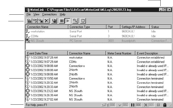
Figure 10 OneTouch® MeterLink™ software window
The MtrLink.ini file, located in the C:\Program Files\LifeScan\MeterLink directory,
contains information for all connections that have been added. Once you have established
the connection list, save a copy of the MtrLink.ini file to a safe location on a separate
storage device. In the event you need to restore the file, contact LifeScan for assistance.
Event list
Connection
list
Tool bar
Status bar
Menu bar
Minimize button
ethernet.book Page 22 Friday, October 26, 2007 1:08 PM

23
Event List
Below the connection list is the event list, which displays the date, time, and description
of the recorded events for each connection. Events may include establishing, halting,
restarting, or removing a connection, as well as transferring data. Each event is preceded
by an icon.
– indicates the event is a normal occurrence.
– indicates the event is an error or failure.
■NOTE: An error event is normal for the wireless unit in power-saving mode.
After 400 events, the software automatically replaces the oldest event with a new event on
a first-in-first-out basis. You can scroll through the list to see each event and description.
The software also creates a daily log file. The file contains a list of all events that occurred on
that day. The files are named by the date they were created, for example, 20020123.log
(YYYYMMDD format) and are located in the C:\Program Files\LifeScan\MeterLink\MLLog
directory. The window’s title bar displays the current event log name and path.
■NOTE: Certain event descriptions, for example, error messages, may be truncated
within the event list, making them difficult to interpret. To see an error
message in its entirety, refer to the log file. A description of the most common
error messages can be found in the Troubleshooting section.
Tool Bar
The tool bar contains the same commands that are found in the menu bar. Place the cursor
over an icon in the tool bar to display a description of the icon.
■NOTE: The icon descriptions will vary depending on the version of OneTouch®
MeterLink™ software you are using.
▲CAUTION: Do not edit a connection during an active communication session. For
example, halting or removing a connection during communication may
result in unstable communications for subsequent sessions.
Restart
Connection
Halt
Connection
Save
Connection List
Report
Hide
Application
Remove
Connection
Add Serial Port
Connection
Help
Add Network
Device
Connection
Add PC
Server/Client
Connection
ethernet.book Page 23 Friday, October 26, 2007 1:08 PM
24
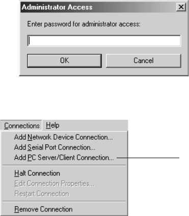
Administrator/Viewer Access Mode
OneTouch® MeterLink™ software operates in two modes, Viewer Access mode and
Administrator Access mode. When you start the computer, the program opens in Viewer
Access mode.
To execute the Administrator mode:
1Select Administrator Access from the File menu.
2Enter the password in the access dialog box.
The password was provided to you by a LifeScan representative during installation.
Administrator Access mode enables the Connections menu, which contains commands for
adding, editing, halting, restarting, and removing connections.
To switch back to Viewer Access mode, select Viewer Access from the File menu or select
Hide Application from the View menu—when you reopen the OneTouch® MeterLink™
window by double-clicking the icon in the notification tray, the window opens in Viewer
Access mode.
You may quit OneTouch® MeterLink™ software from Administrator Access mode only. If
you exit OneTouch® MeterLink™ software and wish to restart the application, click to
Available in OneTouch® MeterLink™, version 3.2
(earliest version that supports OneTouch® DataLink® Sync)
ethernet.book Page 24 Friday, October 26, 2007 1:08 PM
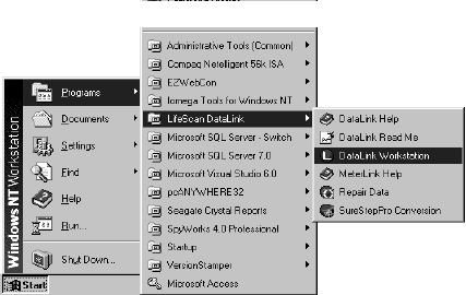
25
open the Start menu, point to Programs, point to LifeScan DataLink, and then click
DataLink Workstation.
▲CAUTION: OneTouch® MeterLink™ software must be running to establish a network or
serial port connection. If you quit OneTouch® MeterLink™, all connections
are halted and meters cannot communicate with the workstation. Although
no data is lost, no data will be transferred to the workstation.
Establishing a Connection with a Serial Server, Terminal Server, or Serial Client
You must be in OneTouch® MeterLink™ Administrator Access mode to establish a
network device (serial server, terminal server, or serial client) connection. Select
Administrator Access from the File menu and enter the password. Use this option to
establish a connection with the wireless unit.
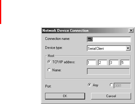
1Select Add Network Device Connection from the Connections menu.
The Network Device Connection dialog box appears. The dialog box may vary
depending on the version of OneTouch® MeterLink™ you are using.
2Enter information in each field:
• Enter up to 20 characters in the Connection name field. This field helps you
identify the server (for example, ICU Wireless for a wireless connection).
• Select Serial Server, Terminal Server, or Serial Client from the Device type drop-
down list. For a wireless unit, select Serial Client.
Once you select the device type you cannot change it. You must remove the
connection and add a new one.
• Click TCP/IP address and enter an IP address for the network device. Or, if you are
using DHCP to assign addresses, click Name and enter the name assigned to the
network device.
• Select the port number, if necessary.
For a serial server, the number defaults to 3001.
ethernet.book Page 25 Friday, October 26, 2007 1:08 PM
26
For a terminal server, enter 3001–3008 (corresponding to ports 1–8).
For a serial client, select Any if the port number is dynamic or if you don’t know the
port number. If the device is configured with a specific port number, you may enter it
(1024–65535). For a wireless unit the default is 10002. (Verify with your Network
Administrator if this setting was changed. See the fourth bullet in step 3 under “For
DHCP” starting on page 18.)
3Click OK.
An entry is added to the connection list. After a few seconds, the status appears as:
• Idle (normal for a serial server or terminal server)
• Listening (normal for a serial client other than a wireless unit)
• Connection failed (normal status for a wireless unit in power-saving mode)
Additionally, the connection event is added to the event list and the log file.
Establishing a Connection with a PC Server/Client
You must have OneTouch® MeterLink™ software, version 3.2 or later, and be in
Administrator Access mode to establish a PC server connection. Select Administrator Access
from the File menu and enter the password.
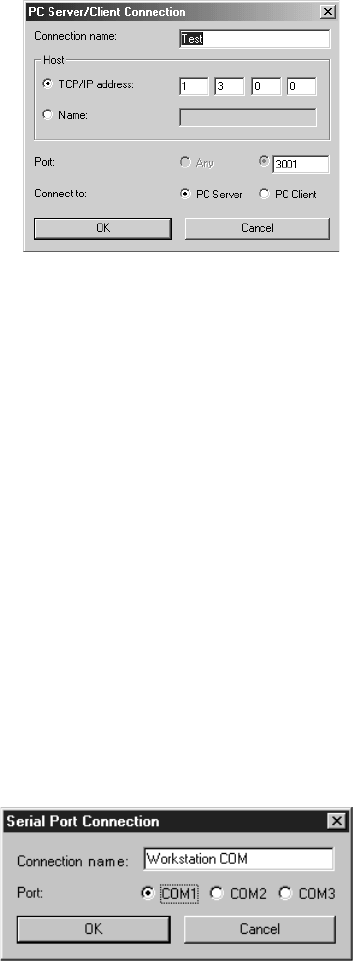
1Select Add PC Server/Client Connection from the Connections menu.
The PC Server/Client Connection dialog box appears. The dialog box may vary
depending on the version of OneTouch® MeterLink™ you are using.
2Enter information in each field:
• Enter up to 20 characters in the Connection name field to identify the PC.
• Click TCP/IP address and enter the static (or reserved) IP address for the PC. Or,
click Name and enter the name assigned to the PC. If DHCP is used for assigning a
variable IP address, select the computer name.
ethernet.book Page 26 Friday, October 26, 2007 1:08 PM
27
• Select the port number, if necessary.
For a PC Server, the number defaults to 3001.
This number must match the port number specified in the OneTouch® DataLink®
Sync Network tab of the Properties window (see page 7).
3Select PC Server for OneTouch® DataLink® Sync.
4Click OK to establish the connection.
■NOTE: OneTouch® DataLink® Sync software must be running on the PC server to
establish a connection.
An entry is added to the connection list. After a few seconds, the status for a PC server
appears as Idle. Additionally, the connection event is added to the event list and the
log file.
Establishing a Connection with the Workstation Serial Port
You must be in OneTouch® MeterLink™ Administrator Access mode to establish a serial
port connection. Select Administrator Access from the File menu and enter the password.
1Select Add Serial Port Connection from the Connections menu.
The Serial Port Connection dialog box appears.
2Enter up to 20 characters in the Connection name field to identify the
connection.
3Select the workstation COM port where the connection will be established.
ethernet.book Page 27 Friday, October 26, 2007 1:08 PM
28
4Click OK to establish the connection.
An entry is added to the connection list. After a few seconds, the status appears as Idle.
Additionally, the connection event is added to the event list and the log file.
Transferring Data
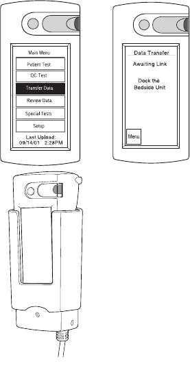
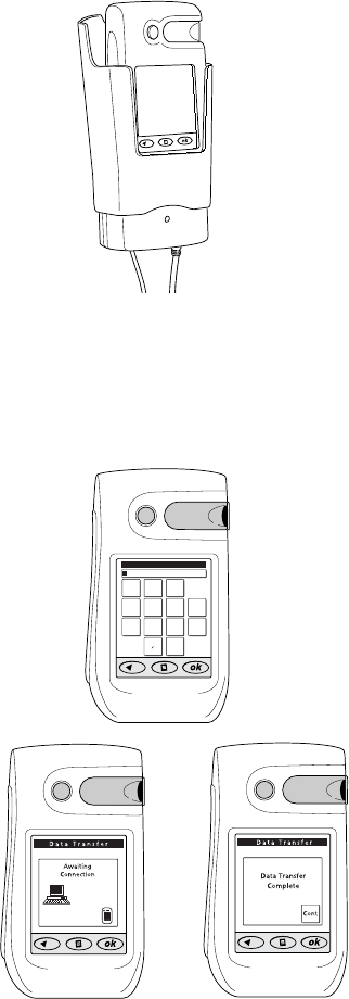
SureStepPro® Bedside Unit
Follow this procedure to transfer data between the SureStepPro® bedside unit and the
workstation using the connection module.
■NOTE: You must perform a bedside unit’s initial configuration at the workstation’s
connection module or through an Ethernet connection. You cannot use the
modem-to-modem configuration until the initial bedside unit configuration is
performed.
1Turn on the bedside unit and press Cont at the Status screen.
2Select Transfer Data from the Main Menu.
A message appears informing you to dock the
bedside unit in the connection module.
3Place the bedside unit in the connection
module.
• If you have an Ethernet configuration, data is
automatically transferred to the workstation
through the network.
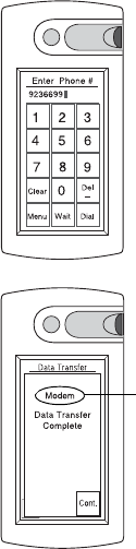
• If a modem is detected, the connection
module automatically dials the receiving
modem (provided the number was
downloaded to the bedside unit from the
workstation, or entered at the bedside unit).
If the line is busy, the connection module
will retry up to 20 times at 30-second intervals before it times out.
■NOTE: If you are sharing the modem with a fax machine, do not start a data transfer
session if a fax is being sent or received—the two cannot occur simultaneously.
ethernet.book Page 28 Friday, October 26, 2007 1:08 PM
29
If the receiving modem phone number was not
downloaded to the bedside unit from the
workstation, the Enter Phone # screen appears.
Enter the phone number for the receiving
modem, then press Dial.
Messages appear on the screen indicating the
status of the connection.
The indicator light on the connection module
blinks during the transfer of data. A message
appears when data transfer is complete.
4Remove the bedside unit from the
connection module cradle and press Cont.
■NOTE: If the bedside unit is off when you remove it from the connection module, you
can verify that the transfer was successful by turning on the bedside unit. If an
error occurred during transfer, the following message appears after the status
screen: Last Data Transfer mm/dd/yy hh:mm Failed. Additionally, the bedside unit
displays the date and time of the last successful upload at the Main Menu.
OneTouch® Flexx™ Meter
The following procedures explain how to transfer data between the OneTouch® Flexx™
meter and the workstation, using a connection module, a serial cable, or the OneTouch®
DataLink® Wireless unit.
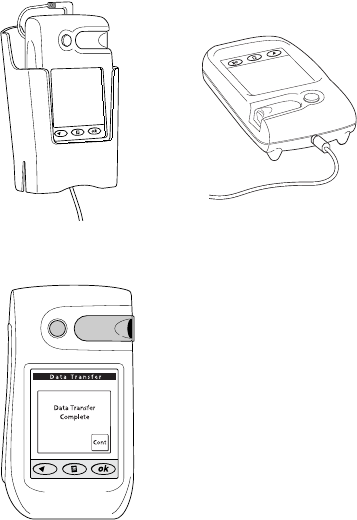
Using a Connection Module
A connection module allows you to transfer data from remote locations, either through
modems or over a network. When the meter is placed in the connection module, the
infrared ports on the meter and connection module are aligned and data is transferred via
infrared communication.
The connection module may be connected to a PC server, serial server/client, modem, or
directly to the workstation’s serial port.
■NOTE: If you are transferring data over a modem and a fax machine is sharing the same
analog line as the modem, do not transfer data while a fax is being sent or
received.
<
Appears for modem
transfer only.
ethernet.book Page 29 Friday, October 26, 2007 1:08 PM
30
1Place the meter into the connection
module cradle.
The connection module turns on the meter.
• If you have an Ethernet configuration, data
is automatically transferred to the
workstation through the network.
• If a modem is detected, the connection
module automatically dials the receiving
modem (provided the number was
downloaded to the meter from the
workstation, or entered at the meter).
If the line is busy, the connection module
retries up to 20 times at 30-second
intervals before it times out.
If the receiving modem phone number was
not downloaded to the meter from the
workstation, the Enter Phone # screen
appears.
Enter the phone number for the receiving
modem, then press Ok.
Messages appear on the screen indicating the
status of the transfer. The meter beeps and a
message appears when data transfer is
complete.
2Remove the meter from the connection module cradle and press Cont.
If the meter is off when you remove it from the connection module, you can verify that
the transfer was successful by turning on the meter. If an error occurred during the
transfer, the following message appears after the status screen: Last Data Transfer mm/
dd/yy hh:mm Failed. Additionally, the status of the last upload appears at the status
screen.
connection module and cradle
123
456
789
0
CLR
DEL
Enter Phone #
WAIT
ethernet.book Page 30 Friday, October 26, 2007 1:08 PM
31
Using a Serial Cable
A serial cable may be used to transfer data between the meter and the workstation. Use the
built-in serial cable in the cradle to connect to a PC server, serial server/client, modem, or
the workstation’s serial port. Or, use the OneTouch® DataLink® serial cable for a direct
connection to the workstation.
1Connect the serial cable (either the
OneTouch® DataLink® serial
cable or the cable in the cradle) to
the meter.
Messages appear on the screen
indicating the status of the transfer.
The meter beeps and a message
appears when data transfer is
complete.
2Unplug the serial cable from the meter and press Cont.
If the meter has turned off, you can verify that the transfer was successful by turning
on the meter. If an error occurred during the transfer, the following message appears
after the status screen: Last Data Transfer mm/dd/yy hh:mm Failed. Additionally, the
status of the last upload appears at the status screen.
serial cable in cradle serial cable
ethernet.book Page 31 Friday, October 26, 2007 1:08 PM
32
Using a Wireless Unit
1Perform a glucose test.
• If the meter is in the tote and connected to the
wireless unit, data transfer begins automatically
at the completion of each test.
• If you are testing with the meter outside the
tote, plug the meter into the wireless unit
using the serial cable. The meter turns on
automatically and data transfer begins.
■NOTE: It is not recommended to lift the antenna during data transfer.
A steady green ACTIVITY LED indicates communication with OneTouch®
MeterLink™.
2Following data transfer:
• To continue testing with the meter connected to the wireless unit, turn off the
meter and turn it on again.
• To continue testing with the meter outside the tote, remove the serial cable from
the meter and press Cont if the meter is still on.
■NOTE: When you turn on the meter while it is connected to the wireless unit or
when you plug the meter into the wireless unit using the serial cable, you
have approximately 15 seconds from the time the main menu appears until
you need to select an option before the meter automatically attempts a data
transfer.
If the meter has turned off, you can verify that the transfer was successful by turning on
the meter. If an error occurred during the transfer, the following message appears after the
status screen: Last Data Transfer mm/dd/yy hh:mm Failed. Additionally, the status of the last
upload appears at the status screen.
After approximately 60 seconds or when communication has finished, the wireless unit
will go into a power-saving mode.
serial cable
ethernet.book Page 32 Friday, October 26, 2007 1:08 PM

33
Troubleshooting
OneTouch® MeterLink™ Event Errors
Following is a list of the more common OneTouch® MeterLink™ event errors.
Meter Error Messages
Error Message Cause Solution
Connection reset by
peer
1. PC server was turned off, or
the user logged off or exited
OneTouch® DataLink® Sync.
2. The network device is turned
off or disconnected.
1. Check the PC server to ensure that it is turned on,
connected to the network device, and that OneTouch®
DataLink® Sync is running.
2. Check the network device to ensure it is turned on and
connected to the network.
Failed to locate client 1. OneTouch® MeterLink™
cannot ping the serial client.
2. Wireless unit may be in
power-saving mode.
1. Check the serial client to make sure it is turned on and
connected. Verify that the IP address/name is correct.
2. This is normal behavior if the serial client is a wireless unit
in power-saving mode.
Graceful shutdown in
progress
1. PC server was turned off, or
the user logged off or exited
OneTouch® DataLink® Sync.
2. The network device is turned
off or disconnected.
1. Check the PC server to ensure that it is turned on,
connected to the network device, and that OneTouch®
DataLink® Sync is running.
2. Check the network device to ensure it is turned on and
connected to the network.
Invalid or already used
IP address/port
Connection could not be
established with specified IP
address/name and specified port
(if not “Any”).
Check the serial server or terminal server to make sure it is
turned on and connected. Verify that the device’s IP address
or name was correctly entered in OneTouch® MeterLink™.
Error Message Cause Solution
Awaiting
Communications
Link
(This message may also
indicate meter status.)
1. Modem not detected.
2. Connection module or meter
modem hardware error.
1. Make sure:
a. The meter is docked in the connection module.
b. The phone cable is securely connected between the
connection module and modem.
c. The connection module is plugged in.
d. The modem is plugged in and turned on.
e. The modem switches are set properly.
2. Contact LifeScan.
Check
Connections at
Meter
Modem detected but link was
broken.
Make sure meter is positioned in the connection module. Do
not move the meter until the transfer is complete.
ethernet.book Page 33 Friday, October 26, 2007 1:08 PM

34
Check
Connections
at
Workstation
1. No connection established
after five retries because of
“no carrier” error.
2. Wrong phone number
entered at meter.
3. Workstation modem
hardware error.
1. Make sure:
a. The workstation modem is plugged in and turned on.
b. The workstation modem is connected to the wall phone
jack.
2. Enter the correct receiving modem phone number.
3. Contact LifeScan.
Check
Phone Line
Connections at
Meter
1. No connection established
after five retries because no
dial tone was detected.
2. Phone line error.
1. Make sure:
a. The meter modem phone line is not being used by
another device, for example a fax machine.
b. The modem is connected to the wall phone jack.
2. Have telephone line inspected.
Data Transfer
Connection Lost
Meter connection broken or
interrupted during data transfer.
Do not remove meter from connection module or serial cable
until data transfer is complete.
Invalid
Phone Number
Phone number entered is not
valid.
Phone number was not entered, or more than four pause
characters were entered.
Meter Disabled Meter deleted from system or
unassigned.
Contact system administrator for current status of meter.
Assign meter to location, then perform data transfer with
workstation.
Meter Not Recognized
by Workstation
Meter not part of OneTouch®
DataLink® system.
Contact system administrator to add meter to system.
Modem not
Supported
Modem model not supported by
software.
Use recommended modem. Contact LifeScan for modem
models supported.
Phone Line Busy
at
Workstation
1. No connection established
after 20 retries because of
busy signal.
2. Receiving modem phone line
being used by a fax machine.
3. Phone line error.
1. Multiple meters are attempting to communicate
simultaneously with the workstation.
2. Receiving modem phone line must be a dedicated line. Do
not share line with a fax machine.
3. Have telephone line inspected.
Error Message Cause Solution
ethernet.book Page 34 Friday, October 26, 2007 1:08 PM

35
Wireless Unit LED Error Conditions
Following is a list of the wireless unit indicator light error conditions. If you encounter any
of the hardware or software conditions, contact LifeScan’s Healthcare Professional Line at
1 800 524-7226.
Wireless Unit
LED Status Meaning
LOW BATT (red) blinking 3 times in 4 seconds Hardware error: network controller
blinking 4 times in 4 seconds Hardware error: MAC address
ACTIVITY (green) blinking 5 times in 4 seconds Software error: duplicate IP address present
blinking 6 times in 4 seconds Software error: no DHCP response
WIRELESS (yellow)
LOW BATT (red)
both LEDs blink sporadically Wireless unit needs to be charged
Problem Cause Solution
Wireless unit will not
hold a charge.
Battery low after long-term
storage.
Wireless unit battery requires reformation. Refer to
“Reforming the Wireless Unit Battery” on page 20. If you
continue to have problems, repeat the reformation
procedure.
Meter times out and
will not communicate
1. DHCP name contains invalid
characters.
1. Ensure that the DHCP name contains alphanumeric
characters only. The system does not accept special
characters, such as (–), (/), (\), (#), (:), (;), (space).
2. Security set improperly. 2. Ensure that the security parameters and authentication of
your wireless network are properly entered into the
wireless unit. If the unit has trouble authenticating to your
access points, settings such as Encryption, MAC Filtering,
Open System/Shared Key authentication, as well as
incorrect casing of SSID are common areas to review.
3. DHCP name resolution taking
too long.
3. Ensure the IP address field for DHCP is set to 0.0.5.0.
Refer to “Configuring Network Parameters and Channel
Settings” on page 17.
4. Slow transmission speed. 4. Ensure that the Data Rate setting is optimized for your
network. Refer to “Configuring Network Parameters and
Channel Settings” on page 17.
5. Problem with connection to
workstation.
5. Refer to the “Ethernet Connection from the Workstation”
troubleshooting table on page 38.
ethernet.book Page 35 Friday, October 26, 2007 1:08 PM
Wireless unit does not show any LED on when connected to Meter:
Wireless unit in shut down (battery cutoff) mode due to operation beyond
low battery. Need to have a re-charge

36
Ethernet Connection from the PC Server
If you are not able to successfully transfer data between the meter, connected to the PC
server, and the workstation, open OneTouch® MeterLink™ software at the workstation
and verify that the list of connections is correct. Then proceed through the following
possible causes and solutions. If you still cannot resolve the problem, proceed to “Ethernet
Connection from the Meter Location” on page 37 to rule out problems with hardware or
hardware connections.
Problem Cause Solution
Cannot transfer data
between the meter
(connected to a PC
server) and the
workstation
1. OneTouch® DataLink® Sync
is not installed on the PC.
1. Follow the instructions “Installing OneTouch®
DataLink® Sync Software on a PC Server” on page 4.
Then, proceed to “Using OneTouch® DataLink® Sync
Software” on page 6 for information on configuring the
software.
2. OneTouch® DataLink® Sync
is not running on the PC.
2. OneTouch® DataLink® Sync starts automatically when
you start your PC. Do not exit the program. It must be
open to allow communication to occur. If you need to
restart the program, double-click the application icon on
the desktop.
ethernet.book Page 36 Friday, October 26, 2007 1:08 PM

37
Ethernet Connection from the Meter Location
If you are not able to successfully transfer data between the meter and the workstation, and
you have established that all network connections and settings are valid, proceed through
the following flow chart to eliminate any problems with hardware or hardware
connections.
Problem Cause Solution
Cannot transfer data
over a network, from
the meter to the
workstation
1. Meter battery power is low. 1. Check the meter battery status to ensure adequate power.
The meter’s battery power may be too low to operate the
barcode scanner. If this happens the Scan button does not
appear on the data entry screens. Replace the batteries if
necessary.
If you are using a SureStepPro® bedside unit with a
connection module, turn on the bedside unit and select
Transfer Data from the Main Menu before placing the unit
in the connection module.
2. Meter has old version of
software.
2. Upgrade meter software.
3. OneTouch® MeterLink™ is
not open and running at the
workstation.
3. Call the lab to see if OneTouch® MeterLink™ is running.
Ensure the list of connections is correct.
4. Loose hardware or power
connection.
4. Check the connection module and serial or terminal
server connections and power plugs. If using a wireless
unit, ensure serial cable is securely connected between
meter and wireless unit. Ensure all connections are
secure.
5. Problem with meter. 5. Try another meter in the connection module or tote (if
using a wireless unit). If it works, there may be a problem
with the meter. Contact LifeScan’s Healthcare Professional
Line at 1 800 524-7226.
6. Data transfer was interrupted
because a meter button was
pressed.
6. Once communication begins do not attempt any other
operations. Allow data transfer to complete.
ethernet.book Page 37 Friday, October 26, 2007 1:08 PM

38
Ethernet Connection from the Workstation
If you are not able to successfully transfer data between the meter and the workstation over
a network, open OneTouch® MeterLink™ software at the workstation and verify that the
list of connections is correct. Then proceed through the following possible causes and
solutions. If you still cannot resolve the problem, proceed to “Ethernet Connection from
the Meter Location” on page 37 to rule out problems with hardware or hardware
connections.
Problem Cause Solution
Cannot receive data at
the workstation when
transferring from a
meter over a network
1. The network connection was
lost.
1. Check all hardware connections to ensure they are secure.
2. OneTouch® MeterLink™ is
displaying the connection as
red, indicating an error.
NOTE: This is normal behavior
for the wireless units.
2. Halt the connection, then restart it. Refer to the Event
Description in OneTouch® MeterLink™ for details on the
error.
3. The serial port and/or
network device configuration
settings in OneTouch®
MeterLink™ are incorrect.
3. Check the serial port and network device configuration
settings in OneTouch® MeterLink™. Edit, if necessary. Try
transferring data again.
4. The IP address/name was not
entered correctly in
OneTouch® MeterLink™.
4. Assign or reset the IP address. Ping the server to verify
that the IP address is correct. If you can successfully ping
the server, reboot it by turning it off, then on. Try
transferring data again. See also #5 below.
5. If you have a DHCP server, the
IP addresses are dynamic.
5. Enter the name for the server, instead of the IP address.
You may also disable DHCP so that IP addresses are
static. If you continue to have problems, enter the fully
qualified domain name (FQDN).
6. Network problems. 6. If the IP address is correct and you tried pinging the server
but were unsuccessful, try pinging another device on the
network. If you cannot ping the device, contact your
network administrator. If you continue to have problems,
contact LifeScan’s Healthcare Professional Line at 1 800
524-7226.
ethernet.book Page 38 Friday, October 26, 2007 1:08 PM

39
Specifications
Connection Module
Dimensions and weight:
connection module
wall mount cradle
width 3.5 in
length 2.25 in
height 2.75 in
weight 5.6 oz (without cables)
SureStepPro®OneTouch® Flexx™
width 4.10 in 4.21 in
depth 2.87 in 2.89 in
height 5.95 in 6.76 in
weight 4.0 oz 4.7 oz
Power supply: 120V ±10%, 60 Hz
Operating temperature: 15°–35°C (59°–95°F)
Operating humidity: up to 90% relative humidity (noncondensing)
Communication status indicator:
1. Ready/standby
2. Communication in progress
3. Power failure
solid green
flashing green
no light
RS-232 compliant signals: Serial Data Transmit
Serial Data Receive
Data Terminal Ready
Common (ground)
OneTouch® DataLink® complies with the following standards:
• CAN/CSA–C22.2 No 950-95 Safety of Information Technology Equipment, Including Electrical
Business Equipment (3rd Edition)
• UL 1950–95 Safety of Information Technology Equipment, Including Electrical Business
Equipment (3rd Edition)
ethernet.book Page 39 Friday, October 26, 2007 1:08 PM
40
Wireless Unit
Dimensions and weight: width 4.3 in
depth 0.9 in
height 3.5 in (including antenna)
weight 13 oz (without serial cable)
Operating temperature: 0°–50°C
Operating humidity: up to 95% relative humidity (noncondensing)
Wireless: OneTouch® DataLink® Wireless unit is 802.11b
standard compliant which ensures it is interoperable
with existing 802.11b/g environments.
The wireless unit complies to the following standards:
• UL 60950-1 UL Standard for Safety of Information Technology Equipment
• CAN/CSA C22.2 No 60950-1-03 Safety of Information Technology Equipment
• CFR Title 47 FCC Part 15, Subpart 15, Class B
• FCC Part 15, Subpart B, Class B
• Industry Canada ICES-003, Issue 4 (2004), Class B
FCC/IC NOTICE:
This device meets the body worn human exposure limits found in OET Bulletin 65, 2001, and ANSI/IEEE C95.1, 1992. Proper
operation of this radio according to the instructions found in this guide will result in exposure substantially below the FCC’s
recommended limits.
To comply with the FCC and ANSI C95.1 RF exposure limits, this device has been tested for compliance with FCC RF Exposure
(SAR) limits in the typical configuration. It is recommended that the antenna must not be co-located or operating in conjunction
with any other antenna or radio transmitter.
NOTE: The radiated output power of this wireless device is far below the FCC radio frequency exposure limits. Nevertheless,
this device should be used in such a manner that the potential for human contact (ie, touching the wireless unit) during normal
operation is minimized.
THIS MODEL DEVICE MEETS THE GOVERNMENT’S REQUIREMENTS FOR EXPOSURE TO RADIO WAVES:
Your wireless device is a radio transmitter and receiver. It is designed and manufactured not to exceed the emission limits for
exposure to radiofrequency (RF) energy set by the Federal Communications Commission of the U.S. Government. These limits are
part of comprehensive guidelines and establish permitted levels of RF energy for the general population. The guidelines are based
on standards that were developed by independent scientific organizations through periodic and thorough evaluation of scientific
studies. The standards include a substantial safety margin designed to assure the safety of all persons, regardless of age and health.
The exposure standard for wireless devices employs a unit of measurement known as the Specific Absorption Rate, or SAR. The
SAR limit set by the FCC is 1.6W/kg. Tests for SAR are conducted using standard operating positions specified by the FCC with
the device transmitting at its highest certified power level in all tested frequency bands. Although the SAR is determined at the
highest certified power level, the actual SAR level of the device while operating can be well below the maximum value. Before a
device model is available for sale to the public, it must be tested and certified to the FCC that it does not exceed the limit
established by the government-adopted requirement for safe exposure. The tests are performed in positions and locations (e.g.,
next to the body) as required by the FCC for each model. The FCC has granted an Equipment Authorization for this model device
with all reported SAR levels evaluated as in compliance with the FCC RF emission guidelines. SAR information on this model
device is on file with the FCC and can be found under the Display Grant section http://www.fcc.gov/oet/fccid after searching on
FCC ID: R68WIBATT.
ethernet.book Page 40 Friday, October 26, 2007 1:08 PM
FCC ID: R68WIBATTV2
41
Glossary
802.3 Defined by the IEEE, these standards govern the use of the CSMA/
CD (Carrier Sense Multiple Access/Collision Detection) network
access method used by Ethernet networks.
access point A device that allows wireless-equipped computers and other devices
to communicate with a wired network.
address See IP address.
connection module LifeScan’s remote connectivity device that allows you to transfer data
between the meter and workstation. The connection module can be
connected to, and transfer data via, modems, a network (through an
Ethernet connection), or locally through the workstation serial port.
DHCP Dynamic Host Configuration Protocol. A protocol that computers
use to obtain configuration information. DHCP allows a computer
to be assigned an IP address without requiring a manager to
configure information about the computer in a server’s database.
Ethernet A local area network (LAN) developed by Xerox, Digital, and Intel,
and subsequently adopted by the IEEE as a standard that
interconnects personal computers. OneTouch® DataLink® uses an
IEEE 802.3 compliant Ethernet.
EZWebCon A Lantronix software application that allows you to assign IP
addresses for, and configure, Lantronix serial servers and terminal
servers prior to establishing connectivity with the workstation.
hub An electronic device that implements a network. Computers
connected to a hub can communicate as if they are attached to a
network.
IEEE Institute of Electronic and Electrical Engineers. A major standards-
setting group in the United States.
ethernet.book Page 41 Friday, October 26, 2007 1:08 PM
42
IP address A name, set of numbers, or sequence of bits used to identify devices
on a network. Each computer, printer, server, or other device on the
network must have a unique address. Addresses are necessary so that
information transmitted on the network will get to the right
destination.
modem A device that transforms digital information into an analog signal
and vice versa for transmission across phone lines. A pair of modems
allows you to transmit data from the connection module to the
workstation through analog phone lines.
modem connector A DB25 male to RJ11 connector that plugs into the modem and
connects the modem to the meter connection module.
modem-to-serial
server cable
A DB25 male to DB25 female molded cable that connects a modem
to a serial server.
network A system of computers and peripherals connected by some media
and capable of communication.
network device A device (serial server, terminal server, or serial client) that connects
a connection module or modem to a network through an Ethernet
connection.
network patch cable
(RJ45)
A twisted-pair cable used for transmitting information across an
Ethernet network.
OneTouch® DataLink®
Sync software
The communications software running on a nursing unit PC, which
allows you to transfer data from a meter connected to the PC to the
OneTouch® DataLink® workstation over the network.
OneTouch®
MeterLink™ software
LifeScan’s software application that establishes a connection between
a meter and the OneTouch® DataLink® workstation. The software
opens a local serial port to the workstation and a TCP/IP socket to
each PC server or network device (serial server, terminal server, or
serial client).
ethernet.book Page 42 Friday, October 26, 2007 1:08 PM
43
PC server The computer running OneTouch® DataLink® Sync software and
networked to the OneTouch® DataLink® workstation. The PC
server uses OneTouch® DataLink® Sync software to communicate
with OneTouch® MeterLink™ software on the workstation,
allowing you to transfer data from a meter to the workstation over
an Ethernet network.
phone cable (RJ11) A cable used for transmitting information across analog phone lines.
PING Packet InterNet Groper. A program used to test network
connectivity. PING sends a request message to a destination, and
reports whether it receives a reply as expected.
To PING a device, access the DOS prompt, then type ping, followed
by a space, and the IP address (example: ping 154.1.80.82). Press
Enter.
protocol A set of rules for communication between two or more computers.
OneTouch® DataLink® uses the TCP/IP protocol suite.
serial client A device that connects a connection module or modem to a network
through an Ethernet connection. A serial client may also be a
wireless unit, which allows you to connect a OneTouch® Flexx™
meter to a workstation via a network enabled for wireless access. The
serial client connection is active only when the meter is
communicating with the workstation. The serial client is
configurable and communicates using TCP/IP.
serial modem cable A DB25 male to DB9 female molded cable that connects a modem
to the workstation’s serial port.
serial port connector A DB9 female to RJ11 connector that plugs into the workstation’s
serial port and connects the workstation to a meter connection
module.
serial server A device that connects a connection module or modem to a network
through an Ethernet connection. The serial server connection is
constant, even when the meter is not communicating with the
workstation. The serial server is configurable and communicates
using TCP/IP.
ethernet.book Page 43 Friday, October 26, 2007 1:08 PM
44
serial server connector A DB25 female to RJ11 connector that plugs into the modem and
connects the modem to a serial server.
TCP/IP Transmission Control Protocol/Internet Protocol. A widely used
industry protocol suite for connecting computer equipment. TCP/IP
is fully compatible across different hardware platforms, allowing
computers from different vendors to interoperate and share data and
services. Although the suite has many protocols, TCP and IP are two
of the most important.
terminal server A device that connects up to eight receiving modems to a network
through an Ethernet connection. The terminal server is configurable
and communicates using TCP/IP.
terminal server
connector
A DB25 male to RJ45 connector that plugs into the modem and
connects the modem to a terminal server.
wireless unit A serial client device which allows you to transfer data from the
OneTouch® Flexx™ meter to the workstation through a network
enabled for wireless access. After you connect the meter to the
wireless unit using the serial cable, data is transmitted from the
wireless unit through an access point installed on the network.
workstation A high-performance computer specialized for a certain application.
The OneTouch® DataLink® workstation uses the Windows®
operating system and OneTouch® DataLink® Data Management
System.
ethernet.book Page 44 Friday, October 26, 2007 1:08 PM
45
A
adding
PC server connection 26–27
serial server/client connection 25–26
terminal server connection 25–26
wireless connection 25–26
workstation serial port connection 27–28
C
cable
connection module serial cable 31
DataLink serial cable 31
wireless serial cable 32
COM port
PC server 6
workstation 27
configuration options
DataLink Sync 3, 4–9
diagram 1
direct connection 2
modem 2, 9–10
network 2, 10–13
wireless 10
configuring
DataLink Sync 6–7
wireless unit 16–19
connecting
connection module to modem 9
connection module to PC server 6
connection module to serial server/client 10
connection module to workstation 14
modem to serial server/client 12
modem to terminal server 13
modem to workstation 15
connection module
connecting to modem 9
connecting to PC server 6
connecting to serial server/client 10
connecting to workstation 14
connection module cradle serial cable 31
D
data
transferring 28–32
data transfer
failed 29, 30, 32
DataLink serial cable 31
DataLink Sync
configuring 6–7
installing 4–5
starting 7
DataLink Sync configuration 3, 4–9
direct connection 2, 14
E
Ethernet network 1
I
installing
DataLink Sync 4–5
M
meter
data transfer 28–32
types 1
MeterLink software
administrator access 24
application window 21–23
connecting to PC server 26
connecting to serial server, terminal server,
or serial client 25
connecting to workstation serial port 27
connection list 21–22
event list 23
log file 23
starting 21, 24
tool bar 23
Index
ethernet.book Page 45 Friday, October 26, 2007 1:08 PM
46
using 21–28
viewer access 24
modem
configuration 2, 9–10
connecting to connection module 9
connecting to serial server/client 12
connecting to terminal server 13
connecting to workstation 15
multiple receiving 13
using with a fax machine 9
modem switches
receiving modem 12, 13, 15
sending modem 9
N
network configuration 2
using DataLink Sync with PC 4–9
using modems 11–13
using serial server/client 10–12
using terminal server and modems 13
wireless 10
O
OneTouch Flexx meter
transferring data using connection module
29–30
P
PC server
adding connection 26–27
connecting to connection module 6
requirements 3
R
reforming wireless unit battery 20
S
serial cable
DataLink 2, 14, 31
in connection module cradle 9, 11, 14, 31
wireless unit 32
serial server/client
adding connection 25–26
adding wireless connection 25
connecting to connection module 10
connecting to modem 12
in network configuration 2
starting
DataLink Sync software 7
MeterLink software 21
SureStepFlexx meter
transferring data using serial cable 31
transferring data using wireless unit 32
SureStepPro bedside unit
transferring data 28–29
T
TCP/IP
address for network device 25
address for PC server 26
MeterLink connection over network 21
terminal server
adding connection 25–26
connecting to modem 13
in network configuration 3
transferring data 28–32
from OneTouch Flexx meter 29–32
from SureStepPro bedside unit 28–29
using connection module 29–30
using DataLink Sync 8–9
using serial cable connection 31
W
wireless unit 1, 16
battery, reforming 20
charging 19
cleaning 20
LED descriptions 16
serial cable 32
setting up 16–19
workstation
connecting to connection module 14
connecting to modem 15
name 5
workstation serial port
adding connection 27–28
ethernet.book Page 46 Friday, October 26, 2007 1:08 PM