lantronix XPICO200 xPico 200 Series Wi-Fi IoT Gateway module User Manual xPico 200 Series
lantronix xPico 200 Series Wi-Fi IoT Gateway module xPico 200 Series
Contents
User Manual
Part Number 900-818a
Preliminary Draft – September 2017
xPico 200 Series
Wi-Fi® IoT Gateway
Module Data Sheet

xPico® 200 Series Wi-Fi® IoT Gateway module Data Sheet 2
Table of Contents
xPico® 200 Series Wi-Fi® IoT Gateway Module Data Sheet 1
List of Figures _____________________________________________________________ 4
List of Tables ______________________________________________________________ 5
1: Functional Description 6
Overview _________________________________________________________________ 6
Applications _______________________________________________________________ 6
Product Features ___________________________________________________________ 7
2: Hardware and Software Description 8
Software Features __________________________________________________________ 9
3: Host Interfaces 13
Ethernet _________________________________________________________________ 13
UART ___________________________________________________________________ 13
Serial Peripheral Interface (SPI) ______________________________________________ 14
USB Device ______________________________________________________________ 15
SDIO Interface ____________________________________________________________ 15
Configurable General Purpose I/O Pins (GPIO) __________________________________ 16
System Pins ______________________________________________________________ 17
Strap Pins _______________________________________________________________ 17
4: IEEE 802.11 Wireless Lan Specifications 18
5: Antenna Connection Options 19
6: General Technical Data 20
7: Electrical Characteristics 21
Recommended Operating Conditions __________________________________________ 21
DC Characteristics – Digital I/O Signals ________________________________________ 21
Dynamic Power Management Modes __________________________________________ 22
Output Power _____________________________________________________________ 24
EVM ____________________________________________________________________ 24
Receive Sensitivity ________________________________________________________ 25
Power, Reset, Wake, Shutdown and Default Timing ______________________________ 26
Memory _________________________________________________________________ 27

xPico® 200 Series Wi-Fi® IoT Gateway module Data Sheet 3
8: Package Description and Mechanical Footprint 28
Pin and Pad Definitions _____________________________________________________ 32
9: Product Information Label 35
10: Evaluation Kit 36
11: Compliance (PLANNED) 37
Federal Communication Commission Interference Statement _______________________ 38
Industry Canada statement: _________________________________________________ 39
RoHS, REACH, and WEEE Compliance Statement _______________________________ 44
12: Ordering Information 45
Contact Information ________________________________________________________ 45
Warranty ________________________________________________________________ 45

xPico® 200 Series Wi-Fi® IoT Gateway module Data Sheet 4
List of Figures
Figure 2-1 xPico 200 Block Diagram ______________________________________________ 8
Figure 2-2 Hosted Microcontroller Mode ____________________________________________ 9
Figure 2-3 Wireless Microcontroller Mode __________________________________________ 10
Figure 7-1 Reset Timing _______________________________________________________ 26
Figure 7-2 Reset to Defaults Timing ______________________________________________ 26
Figure 7-3 Wake Timing _______________________________________________________ 26
Figure 8-1 xPico 200 Enterprise Wi-Fi IoT Wi-Fi Module (Part 1 of 2) ____________________ 28
Figure 8-2 xPico 200 Enterprise Wi-Fi IoT Wi-Fi Module (Part 2 of 2) ____________________ 29
Figure 8-3 Layout Footprint for xPico 200 Enterprise Wi-Fi IoT Module __________________ 30
Figure 8-4 xPico 200 Edge Connector Module dimensions ____________________________ 31
Figure 9-1 xPico 200 Module Label ______________________________________________ 35

xPico® 200 Series Wi-Fi® IoT Gateway module Data Sheet 5
List of Tables
Table 2-1: xPico 200 Series Product Variants ________________________________________ 8
Table 3-1: xPico 200 Ethernet Signal Definitions ____________________________________ 13
Table 3-2: xPico 200 UART Signal Definitions ______________________________________ 14
Table 3-3: xPico 200 Module SPI Signal Definitions __________________________________ 14
Table 3-4: xPico 200 Module USB Signal Definitions _________________________________ 15
Table 3-5: SDIO Interface Pins __________________________________________________ 15
Table 3-6: xPico 200 Module GPIO Signal Definitions ________________________________ 16
Table 3-7: xPico 200 Module System Signal Definitions _______________________________ 17
Table 3-8 xPico 200 Pins ______________________________________________________ 17
Table 4-1: xPico 200 Module Radio Specification ____________________________________ 18
Table 5-1: External Antenna Options ______________________________________________ 19
Table 5-2: On-Module Antenna Option ____________________________________________ 19
Table 6-1: General Technical Data _______________________________________________ 20
Table 7-1: Recommended Operating Conditions for xPico 200 Module ___________________ 21
Table 7-2: DC Characteristics & Digital I/0 Signals ___________________________________ 21
Table 7-3: xPico 200 Power Consumption 2.4Ghz ___________________________________ 22
Table 7-4: xPico 200 Power Consumption 5Ghz _____________________________________ 23
Table 7-5: xPico 200 Module RF Output Power (Preliminary) ___________________________ 24
Table 7-6: xPico 200 Module Wi-Fi EVM ___________________________________________ 24
Table 7-7: xPico 200 Module Rx Sensitivity ________________________________________ 25
Table 7-8 Shutdown Pin Timing __________________________________________________ 27
Table 8-1: xPico 200 Interface Signal Definitions: ____________________________________ 32
Table 9-1: Datamatrix ECC200 Barcode Standard Descriptions _________________________ 35
Table 11-1: Country Certifications (PLANNED) ______________________________________ 37
Table 11-2: Country Transmitter IDs ______________________________________________ 38
Table 11-3: Europe – EU Declaration of Conformity __________________________________ 43
Table 11-4: Approved External Antenna(s) List ______________________________________ 44
Table 12-1: xPico 200 Series Order Information _____________________________________ 45

xPico® 200 Series Wi-Fi® IoT Gateway module Data Sheet 6
1: Functional Description
Overview
The Lantronix® xPico 200 series of embedded IoT Gateway modules offers the smallest and
highly integrated triple-play combo that provides the quickest and most secure on-ramp to your
IoT applications and services.
xPico 200 series delivers always-on dual-band enterprise Wi-Fi, dual-mode Bluetooth
(Bluetooth Classic v2.1+EDR and Bluetooth Low Energy v4.2) as well as Ethernet connectivity
for business critical assets.
It is a stand-alone module that does not require an external host processor for the wireless and
network stack. With customer proven TruPort technology, that includes essential IoT
connectivity firmware, cloud-based management and an integrated device security framework,
xPico 200 series delivers a complete network and IoT connectivity offload solution for any
microcontroller.
In many cases, device manufacturers can use xPico 200 series as the wireless microcontroller
within their device and focus on the application firmware components while leveraging the
integrated secure connectivity and network and cloud service enablement capabilities within
the module.
The high performance xPico 200 series is available in different versions (see
Product Features).
With the xPico 200 family, design engineers and system architects can reduce product
development time and deploy their secure connected devices with confidence that their
products will connect and work as expected.
Applications
For applications that need Ethernet and wireless connectivity options, xPico 200 delivers a
compact combo solution without needing to integrate two different network stacks from
different modules or controllers.
Integrated Bluetooth capability (on xPico 250 model) also enables creating Gateway modules
that need to aggregate Bluetooth sensor devices or provide BLE location enabled services for
the connected products.
Key applications include:
Medical devices
Industrial Machines
Retail/POS
Weighing Scales
Asset and warehouse management
Environmental monitoring
Transportation and Telematics
xPico 200 series is designed for applications in a variety of industries where reliability,
extended operating temperature range, and robust wireless connectivity are business critical.
xPico 200 series is also particularly well-suited for products with long lifecycles in highly

xPico® 200 Series Wi-Fi® IoT Gateway module Data Sheet 7
regulated industries where the constant change in Wi-Fi technologies and certification would
typically make it difficult or cost prohibitive to incorporate a wireless solution.
Product Features
Industrial rated dual-band Wi-Fi (802.11 a/b/g/n) for high performance enterprise IoT
2.4GHz and 5 GHz bands supported
IEEE 802.3 10/100 Mbps Ethernet (RMII)
BT/BLE 4.2 (xPico 250)
On-module antenna or Dual u.fl
Serial (x1), SPI (x1), USB (Device or Host), SDIO, I2C, GPIO
Ethernet MAC(RMII), USB, serial – host interfaces
Simultaneous AP and client (STA), AP only, client (STA) only modes
TruPort Serial, TruPort USB, TruPort Web providing industry’s most compatible device
data access technology
TruPort Security – adding integrated root of trust security and data-at-rest and data-in-
motion encryption, authentication and identification
Direct mobile to device service interface via SoftAP or Wi-Fi Direct®
technologyWPA/WPA2 – Personal and Enterprise Wi-Fi Security
SSL/TLS 1.2 with X.509 Certificate Management
Dual Network Support
Embedded Ethernet to Wi-Fi STA bridge
Integrated Cloud Based Device ManagementWeb API, XML Configuration, Serial
Command API
Modular RF Certification (FCC, IC, ETSI, Japan, AU/NZS, China)
Compact SMT (LGA) Footprint (17mm x 25 mm)
Operating temperature range: -40⁰C to +85⁰C
Wi-Fi Alliance® Certified
5 year limited warranty
xPico® 200 Series Wi-Fi® IoT Gateway module Data Sheet 8
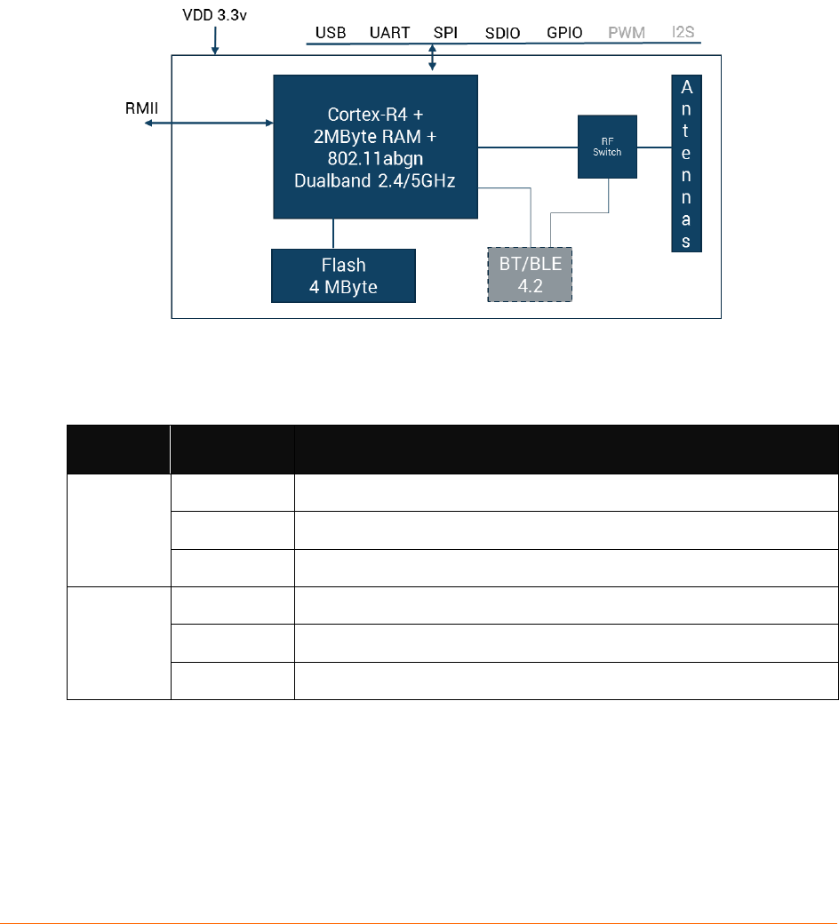
2: Hardware and Software Description
The xPico 200 series is a highly integrated module that includes a Cortex R4 controller, 802.11
a/b/g/n MAC/BB, 10/100Mbps Ethernet MAC, Bluetooth 4.2 (on xPico 250 model), RAM, flash,
and antenna connectors.
The xPico 200 series operated on 3.3V power with 3.3V logic, and has a built-in voltage
supervisory circuit.
Figure 2-1 xPico 200 Block Diagram
Table 2-1: xPico 200 Series Product Variants
Model
Number
Part Number
Description
xPico 240
XPC240100B
xPico 240 Wi-Fi IoT Gateway module, 802.11abgn, Eth, Dual u.fl, Ind.
Temp, LGA, Bulk
XPC240200B
xPico 240 Wi-Fi IoT Gateway module, 802.11abgn, Eth, On-module
Antenna, Ind. Temp, LGA, Bulk
XPC240300B
xPico 240 Wi-Fi IoT Gateway module, 802.11abgn, Eth, Dual u.fl, Ind.
Temp, EdgeConn, Bulk
xPico 250
XPC250100B
xPico 250 Wi-Fi IoT Gateway module, 802.11abgn, Eth, BT/BLE 4.2, Dual
u.fl, Ind. Temp, LGA, Bulk
XPC250200B
xPico 250 Wi-Fi IoT Gateway module, 802.11abgn, Eth, BT/BLE 4.2, On-
module Antenna, Ind. Temp, LGA, Bulk
XPC250300B
xPico 250 Wi-Fi IoT Gateway module, 802.11abgn, Eth, BT/BLE 4.2, Dual
u.fl, Ind. Temp, EdgeConn, Bulk
xPico® 200 Series Wi-Fi® IoT Gateway module Data Sheet 9
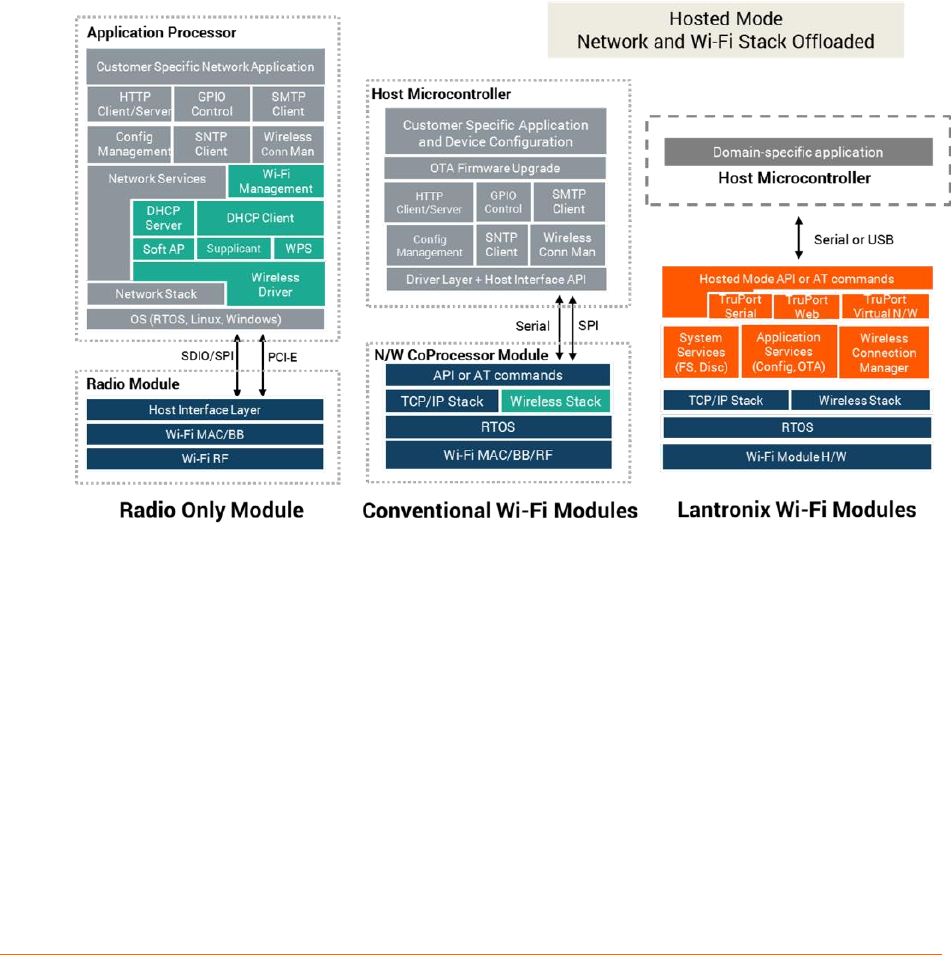
Software Features
xPico 200 software stack provides the essential IoT connectivity infrastructure for building
secure connected products. Device Manufacturers can offload this complexity from their
application microcontroller when interfacing with the module in Hosted Mode or use the
module as the wireless microcontroller in Host-less or Standalone Mode.
Hosted Microcontroller Mode
The module completely offloads all Wi-Fi and secure network connectivity requirements for
attached microcontrollers thereby reducing device firmware complexity while accelerating
OEM’s time to introduce and support secure connected products in the market. The host
interfaces available for connecting to the microcontroller are UART, USB, SPI and Ethernet.
Figure 2-2 Hosted Microcontroller Mode
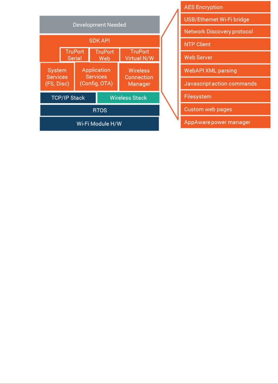
Wireless Microcontroller Mode
In addition to these interfaces, xPico 200 series also offers additional interface such as I2C,
GPIOs and SDIO along with their control lines to support integration with other peripherals and
use as a wireless microcontroller in standalone mode. With the provided SDK, device
manufacturers can leverage not only network and wireless stacks, but also the complete
application framework that includes the configuration management system, reliable remote
OTA firmware upgrades, automated connection management features described below.
xPico® 200 Series Wi-Fi® IoT Gateway module Data Sheet 10
Figure 2-3 Wireless Microcontroller Mode
TruPort Serial
Robust serial to Wi-Fi and serial to Ethernet application that supports transparent transport of
hundreds of serial protocols over the network. TruPort Serial is very suitable for hosted
microcontroller applications with very little to no programming and development effort.
Key capabilities included are:
Support RS232 serial and USB (CDC Serial and CDC ACM Device Classes)
Advanced connectivity modes and configuration knobs to tune the connection parameters
for a specific protocol without requiring custom software programming
Automatic and Manual connect modes
Inbound (Accept Mode) and Outbound (Connect Mode) connections
Modem emulation mode enables connecting to different servers using a standard AT
command set
AES (128-bit, 192-bit, 256-bit) Encrypted session and TLS session modes for secure
tunneling
TruPort Offload
Connect your device microcontroller to multiple services and communicate directly with mobile
devices and cloud services at the same time via TruPort Offload. The simple API for TruPort
Offload is available via the UART or USB interface operating in CDC ACM mode.
Seamlessly switch between data mode and module management mode (CLI access) for total
control and data channel access from your device application microcontroller.
Access TCP, UDP, TLS, HTTP, SMTP channels and communicate with external services
through these channels without implementing these protocol stacks within your microcontroller.

xPico® 200 Series Wi-Fi® IoT Gateway module Data Sheet 11
TruPort Security
Device Manufacturers are exposed to new security risks that emerge with having connected
products. They also have to navigate the engineering complexity of providing integrated security
within their connected devices. Lantronix TruPort Security provides an integrated device security
framework that lets device manufacturers build this into their connected products from the start of
their design cycle instead of as an after-thought or bolted on component.
TruPort Security enables building secure connected products quickly and easily with a full range
of features including:
Secure Boot – run only signed software on device
Secure Connectivity – Enterprise Wi-Fi Security, Data-at-rest and Data-in-motion
authentication and encryption
Encrypted Storage – stored configuration and device data securely
Fine Grained Port Access Control – Prevent back-doors with fine grained control over
network ports
Root of Trust and Device Identity – Certificate Management, Secure Key Storage, OEM
Keys
Ethernet to Wi-Fi Client Bridge
For devices with microcontrollers that include a network stack and also have Ethernet
connectivity available, the Gateway module module software provides wireless connectivity to
these devices via the Ethernet to Wi-Fi Client Bridge mode. In this mode, the Wi-Fi stack is
fully offloaded and managed via the configuration interface. This mode is most suitable for
networked microcontrollers that do not have the resources to integrate wireless device drivers
and add-on the complexity of managing the wireless stack.
Enterprise Wi-Fi Security
Centralized control of security policies and ability to permit and revoke access rights and
scaling to support the large number of devices deployed within the enterprise are primary
considerations that Enterprise Wi-Fi Security addresses. With support for 802.1X, 802.11i and
EAP authentication methods along with support PKI support and X.509 certificate
management, connectivity to the enterprise network is handled via configuration and without
any integration, testing and certification of supplicant and authenticator software.
Wi-Fi Connection Profiles
Connect to multiple wireless networks autonomously by configuring the network parameters
once and then letting the module automatically select the best network to connect to or set
policies for connecting to specific networks. Wi-Fi connection profiles eliminate the need to
manage the state of connection management from the device microcontroller or writing this via
the SDK in wireless microcontroller mode.
Configuration and Management Interface
Access the module configuration and management engine via the microcontroller or via the
network. Command Line Interface (CLI) mode offers a text based interactive interface versus
writing an elaborate driver interface for the AT command and control interface on the device
microcontroller. XML and Web API offer the ability to program the module configuration via the
Over-The-Air (OTA) or Network interface. For more details on the usage of these management
interfaces, please refer to the xPico 200 Command Reference Guide.

xPico® 200 Series Wi-Fi® IoT Gateway module Data Sheet 12
Reliable OTA Firmware Upgrade
As device requirements evolve and new product features are provided, device manufacturers
can leverage the reliable OTA firmware upgrade capabilities to prevent “system bricks”. OTA
firmware upgrade always ensures there is at-least one known version of firmware available in
the event an upgrade operation does not succeed. It operates over the connected network and
does not require placing the module into specific operational modes into order to trigger the
update. Updates can be performed remotely and securely using the included Secure Boot
features.
xPico® 200 Series Wi-Fi® IoT Gateway module Data Sheet 13
3: Host Interfaces
The xPico 200 module offers a number of common interfaces to allow for easy connectivity to
the module. These include 10/100Mbps Ethernet MAC with RMII, UART for asynchronous
serial communication, serial peripheral interface for synchronous formatted data, and USB
host interface.
Ethernet
The xPico 200 module has an integrated 10/100Mbps Ethernet MAC and with an RMII
interface. External PHY, magnetics and RJ45 are required for connection to a standard
Ethernet network. See the xPico 200 Enterprise Wi-Fi IoT Module Integration Guide available
at www.lantronix.com/support/documentation for more details.
Table 3-1: xPico 200 Ethernet Signal Definitions
Pin Name
Description
xPico 200
SMT Pin
Edge connector
pin
RMII_TXD0
RMII TXD0 transmit output
23
73
RMII_TXD1
RMII TXD1 transmit output
24
71
RMII_CLK
RMII interface clock
25
61
RMII_TXEN
RMII transmit enable output
27
67
RMII_RST
RMII reset output
28
70
RMII_RXDV
RMII RX data valid input
30
65
RMII_RXD0
RMII RXD0 receive input
31
55
RMII_RXD1
RMII RXD1 receive input
32
53
MDC
MDIO clock
35
47
MDIO
MDIO data
36
49
UART
The xPico 200 module supports one UART interface
The UART supports asynchronous data rate up to 921 Kbps, with Odd/Even parity, and
1 & 2 stop bits
Software flow control (Xon, Xoff)
Operational mode as a DTE device
UART supports TX, RX, RTS, CTS (hardware flow control)

xPico® 200 Series Wi-Fi® IoT Gateway module Data Sheet 14
Table 3-2: xPico 200 UART Signal Definitions
Pin Name
Description
xPico 200
SMT Pin
Edge
Connector pin
TXD1
Serial transmit data output
48
22
RTS1
Serial ready-to-send / serial transmit enable
output
46
34
RXD1
Serial receive data input
47
32
CTS1
Serial clear-to-send input
42
36
Serial Peripheral Interface (SPI)
The xPico 200 module has a master SPI interface. The SPI is multiplexed with five
configurable GPIO pins and is managed by configuration at system initialization.
Five wire interface consisting of Serial In, Serial Out, Chip Select, Serial Clock and
Interrupt
Table 3-3: xPico 200 Module SPI Signal Definitions
Pin Name
Description
xPico 200
SMT Pin
Edge connector
pin
CP7
Configurable I/O-SPI Clock
10
42
CP8
Configurable I/O-SPI Chip Select
11
40
CP2/INT
Configurable I/O-SPI interrupt input
12
48
CP3
Configurable I/O- SPI MISO
8
46
CP4
Configurable I/O-SPI MOSI
9
44
xPico® 200 Series Wi-Fi® IoT Gateway module Data Sheet 15
USB Device
The xPico 200 module has one USB port interfaces.
The USB 2.0 port supports high speed host and device modes
Support for USB CDC/ACM serial profile
1
which will have the module appear as a
CDC/ACM device enumerated as a virtual COM port.
Table 3-4: xPico 200 Module USB Signal Definitions
Pin Name
Description
xPico 200
SMT Pin
Edge
Connector
pin
USB+
USB Device Port Positive pin
19
3
USB-
USB Device Port Negative pin
20
5
USB_H/D_SEL
USB Host/Device Mode Select
Pull high for device mode on USB port.
Pull low for host mode on USB port
26
12
USB Host Power
Enable (CP2)
Output to enable external USB power switch for
host port connector (Use configurable CP2)
12
48
USB Host Port Over
Current Flag (CP1)
Input from external USB power switch indicating
the host port is over current (Use configurable pin
1)
38
50
SDIO Interface
The xPico 200 has one external SDIO interface which can be run in master or slave mode. The SDIO
port mode (host or slave) is configured by the SDIO mode pin.
Table 3-5: SDIO Interface Pins
Pin Name
Description
Reset State
xPico 200
SMT Pin
Edge
Connector
pin
SDCLK
SDIO Clock1
Input
2
9
SDCMD
SDIO CMD1
Input
3
11
SDIO0
SDIO Data 01
Input
4
13
SDIO1
SDIO Data 11
Input
5
15
SDIO2
SDIO Data 21
Input
6
17
SDIO3
SDIO Data 3
Input
7
19
SDIO_MODE
Pull high for master mode on SDIO port.
Pull low for slave mode on SDIO port.
Input
29
14

xPico® 200 Series Wi-Fi® IoT Gateway module Data Sheet 16
Configurable General Purpose I/O Pins (GPIO)
The xPico 200 module provides up to 12 configurable General Purpose Input/Output (GPIO)
pins. Certain of the GPIOs are multiplexed with other interface functions (e.g. SPI). Mapping of
these functions to CPs will be driven via configuration and applied at system initialization.
Each CP can be configured as a general purpose input, general purpose output, micro-
controller peripheral block or a soft function. These pins are 3.3V CMOS logic level tolerant.
Table 3-6: xPico 200 Module GPIO Signal Definitions
Pin
Name
Description
Reset State
xPico 200
SMT Pin
Edge
Connector
pin
CP1
Configurable I/O-USB Over Current Flag
Input
38
50
CP2/INT
Configurable I/O-SPI interrupt input-USB Host
Port Power Enable Output
Input
12
48
CP3
Configurable I/O- SPI MISO1
Input
8
46
CP4
Configurable I/O-SPI MOSI1
Input
9
44
CP5
Configurable I/O-I2CDATA1
Input
15
58
CP6
Configurable I/O-I2CCLK1
Input
16
60
CP7
Configurable I/O-SPI Clock1
Input
10
42
CP8
Configurable I/O-SPI Chip Select1
Input
11
40
CP15
Configurable I/O-I2CDATA21
Input
13
56
CP16
Configurable I/O-I2CCLK21
Input
14
54
CP17
Configurable I/O-PWM
Input
22
16
CP18
Configurable I/O-PWM
Input
37
62
1
Available in a future release. Contact your local sales representative for availability.

xPico® 200 Series Wi-Fi® IoT Gateway module Data Sheet 17
System Pins
Table 3-7: xPico 200 Module System Signal Definitions
Pin Name
Description
xPico 200
SMT Pin
Edge
Connector
Pin
EXT_RESET#
Unit hardware reset, active low. Drive low for 50 ms to
reboot unit. Signal should be driven high or pulled high
after reset. EXT_RESET# is inactive during module
power down (standby) state. Assert WAKE signal to
come out of low power states prior to asserting reset.
41
52
DEFAULT#
Unit reset to default, active low. Drive low for 6 seconds or
longer to reset unit to default settings. May be left floating
if unused.
57
23
WAKE2
Toggle signal to WAKE from SLEEP or STANDBY state.
WAKE signal is noise sensitive. Filter as close as
possible to the module pin.
17
20
Strap Pins
The xPico 200 module has two strap pins for setting the mode of the USB and SDIO ports.
These pins must be strapped high or low. The mode definitions are listed below.
Table 3-8 xPico 200 Pins
Pin Name
Description
xPico 200
SMT Pin
Edge
Connector
Pin
USB_H/D_SEL
Pull high for device mode on USB port.
Pull low for host mode on USB port.
26
12
SDIO_MODE
Pull high for master mode on SDIO port.
Pull low for slave mode on SDIO port.
29
14
2
Available in a future release. Contact your local sales representative for availability.

xPico® 200 Series Wi-Fi® IoT Gateway module Data Sheet 18
4: IEEE 802.11 Wireless Lan Specifications
The table below provides the specifications and performance attributes for the xPico 200
module IEEE 802.11 radio.
Table 4-1: xPico 200 Module Radio Specification
Feature
Description
Frequency Band
2.412 – 2.484 GHz (channels 1 – 14)
4.9 to 5.845 Ghz
Channels dependent on assigned country code
Supported Data Rates
802.11abgn (20)
a, b, g data rates up to 54 Mbps
n data rates up to MCS7
Modulation
OFDM with BPSK, QPSK, 16-QAM, 64-QAM
801.11b with CCK and DSSS
802.11 MAC Features
WEP, WPA, WPA2, WMM, WMM-PS (UAPSD), WMM-SA, AES, TKIP,
CKIP
802.11 PHY Features
802.11b, 802.11g, 802.11n, 802.11a
802.11 modes
/n/a/b/g/d/h/i

xPico® 200 Series Wi-Fi® IoT Gateway module Data Sheet 19
5: Antenna Connection Options
The xPico 200 module supports wireless connectivity via two U.FL connectors for single
stream transmit and receive diversity.
An on-module stamped metal antenna version is also available as a product SKU option. The
single antenna is used for transmit and receive. Diversity is not available on the module with
the on-module antenna.
The xPico 200 modules are certified using the antennas listed in Table 5-1 and Table 5-2
below.
Refer to the compliance section below for certification requirements related to antenna selection.
Table 5-1: External Antenna Options
Antenna Type
Peak Gain
Typical
Lantronix
Part
Number
Vendor
Vendor Part
Number
Approved
Region
PCB strip antenna
with 50 mm cable to
U.FL connector
With tape backing
2.5 dBi, 2.39 Ghz
to 2.49 Ghz
5dBi, 4.9Ghz to
5.9Ghz
XPW100A
003-01-B
50 piece
bulk pack
Ethertronics
1001077
FCC, IC,
EU,
AUS/NZS,
JPN, China,
Mexico
PCB strip antenna
with 50 mm cable to
U.FL connector
Without tape
backing
2.5 dBi, 2.39 Ghz
to 2.49 Ghz
5dBi, 4.9Ghz to
5.9Ghz
Ethertronics
1000668
FCC, IC,
EU,
AUS/NZS,
JPN, China,
Mexico
Swivel type
antenna, with RP-
SMA(M) connector
2 dBi, 2.4 Ghz to
2.5 Ghz, 2 dBi,
5.15 Ghz to 5.85
Ghz
930-033-R-
ACC
50 piece
bulk pack
Wanshih
WSS002
FCC, IC,
EU,
AUS/NZS,
JPN, China,
Mexico
Swivel type
antenna, with RP-
SMA(M) connector
3.8 dBi, 2.4Ghz to
2.5Ghz,
5.5 dBi, 4.9 Ghz
to 5.8Ghz
Taoglas
GW.71.5153
(Not for EU
use)
FCC, IC,
AUS/NZS,
JPN, China,
Mexico
Note: Antenna gain listed above excludes cable loss.
Table 5-2: On-Module Antenna Option
Antenna Type
Peak Gain Typical
On module stamped metal antenna
0 dBi 2.4 Ghz, 4 dBi 5 Ghz

xPico® 200 Series Wi-Fi® IoT Gateway module Data Sheet 20
6: General Technical Data
Table 6-1: General Technical Data
Category
Description
Firmware
OTA upgradable
Internal Web Server
Serves web pages
Weight
1.654g (with on module antenna option), 1.552g (with two U.FL option)
Material
Metal shell
Temperature
Operating range: -40°C to +85°C (-40°F to +185°F)
Storage range: -40°C to +85°C (-40°F to +185°F)
Relative Humidity
Operating: 5% to 85% no- condensing
Shock/Vibration
Non-operational shock: 500 g’s. Non-operational vibration: 20 g’s.
RAM
2 MB SRAM
Flash
8MB NOR Serial Flash

xPico® 200 Series Wi-Fi® IoT Gateway module Data Sheet 21
7: Electrical Characteristics
Recommended Operating Conditions
Table 7-1 specifies the recommended operation conditions and parameters for optimum
performance of the xPico 200 module.
Table 7-1: Recommended Operating Conditions for xPico 200 Module
Parameter
Symbol
Min
Typ
Max
Units
Voltage
VCC
3.15
3.3
3.45
V DC
Supply Voltage Ripple/droop
VCC pp
± 1%
Extended Operating Temperature
Ta
-40
+85
⁰C
Humidity (non-condensing, relative)
85
%
Power Supply ramp rate
VCC
40
10001
us
1For slower power supply ramp rates it is recommended to assert reset for 50ms after power
reaches 3.15V.
DC Characteristics – Digital I/O Signals
Table 7-2: DC Characteristics & Digital I/0 Signals
Symbol
Parameter/Sig
nal
Min
Typ
Max
Unit
VIL
RESET#
-0.5
0.8
V
VIH
RESET#
2.0
VCC + 0.5
V
VIL
CPx, UART,
JTAG
-0.5
0.8
V
VIH
CPx, UART,
JTAG
2.0
VCC + 0.5
V
VOL
CPx, UART,
JTAG
0.4
V
VOH
CPx, UART,
JTAG
VCC-0.4
V
VIL
SDIO pins
0.25*VCC
V
VIH
SDIO pins
0.625*VCC
V
VOL
SDIO pins
0.125*VCC
V
VOH
SDIO pins
0.75*VCC
V
RPU
39.58
kΩ
RPD
SDIO_MODE
44.57
kΩ
RPU
44.57
kΩ

xPico® 200 Series Wi-Fi® IoT Gateway module Data Sheet 22
Dynamic Power Management Modes
The table below describes the power management modes for the xPico 200 module, along
with their typical and maximum current consumption values.
The xPico 200 module supports power-up and sleep modes within its dynamic power
management framework.
Table 7-3: xPico 200 Power Consumption 2.4Ghz
Parameter
Power
Management
Soft AP
Symbol
Typical
Max
Units
Boot sequence peak
N/A
N/A
ICC
580
mA
Idle current average-unit
connected to AP on client
11n Ch6
OFF
ON
ICC
95
mA
Idle current average-unit
connected to AP on client
11n Ch6
ON,
Beacon 100
ms, DTIM 5
ON
ICC
95
mA
Idle current average unit
connected to AP on client
11n Ch6
ON,
Beacon 100
ms, DTIM 5
OFF
ICC
41
mA
Idle current average unit not
connected to AP on client
OFF
OFF
ICC
TBD
mA
Iperf(UDP) in bridge mode to
AP on client interface 1Mbps-
Sustained
11n Ch6
ON,
Beacon 100
ms, DTIM 5
OFF
ICC
95
mA
Transmitter surge, 11g
54Mbps, 15dBm
N/A
N/A
ICC
345
399
mA
Transmitter surge, 11n, 20
Mhz BW, MCS7, 17 dBm
N/A
N/A
ICC
345
398
mA
Transmitter surge, 11g
54Mbps, 0dBm
N/A
N/A
ICC
298
358
mA
Transmitter surge, 11n, 20Mhz
BW, MCS7, 0dBm
N/A
N/A
ICC
299
356
mA
Stand by, external IO
connections removed @+25C
N/A
N/A
ICC
30
uA
Stand by with external PHY,
other external IO connections
removed @ +25C
N/A
N/A
ICC
97
uA
Ethernet ping, Wi-Fi disabled.
External PHY current not
included
N/A
N/A
Icc
37
mA

xPico® 200 Series Wi-Fi® IoT Gateway module Data Sheet 23
Table 7-4: xPico 200 Power Consumption 5Ghz
Parameter
Power
Management
Soft AP
Symbol
Typical
Max
Units
Boot sequence peak
N/A
N/A
ICC
580
mA
Idle current average-unit
connected to AP on
client 11n Ch48
OFF
ON
ICC
148
mA
Idle current average-unit
connected to AP on
client 11n Ch48
ON,
Beacon
100ms, DTIM 5
ON
ICC
148
mA
Idle current average unit
connected to AP on
client 11n Ch48
ON,
Beacon
100ms, DTIM 5
OFF
ICC
40
mA
Idle current average unit
not connected to AP on
client,
OFF
OFF
ICC
TBD
mA
Iperf(UDP) in bridge
mode to AP on client
interface 1Mbps-
Sustained, 11n Ch48
ON,
Beacon
100ms, DTIM 5
OFF
ICC
134
mA
Transmitter surge, 11a
54Mbps, 14dBm
N/A
N/A
ICC
390
465
mA
Transmitter surge, 11n,
40Mhz BW, MCS7,
14dBm
N/A
N/A
ICC
401
494
mA
Transmitter surge, 11a
54Mbps, 0dBm
N/A
N/A
ICC
316
395
mA
Transmitter surge, 11n,
40Mhz BW, MCS7,
0dBm
N/A
N/A
ICC
334
419
mA
Stand by, external IO
connections removed
@+25C
N/A
N/A
ICC
30
uA
Stand by with external
PHY, other external IO
connections removed @
+25C
N/A
N/A
ICC
97
uA
Ethernet ping, Wi-Fi
disabled.
External PHY current not
included
N/A
N/A
Icc
37
mA
xPico® 200 Series Wi-Fi® IoT Gateway module Data Sheet 24
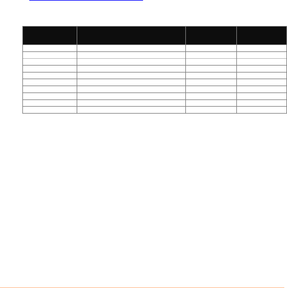
Output Power
xPico 200 module RF output power is listed in the Table 7-4 below.
Table 7-5: xPico 200 Module RF Output Power (Preliminary)
Characteristics
TYP.
Criteria
Unit
RF Average Output Power, 802.11b
1 Mbps
17
+ 2
dBm
11 Mbps
17
+ 2
dBm
RF Average Output Power, 802.11g
6 Mbps
15
+ 2
dBm
54 Mbps
15
+ 2
dBm
RF Average Output Power, 802.11n (2.4Ghz)
MCS0
15
+ 2
dBm
MCS7
15
+ 2
dBm
RF Average Output Power, 802.11a
6 Mbps
15
+ 2
dBm
54 Mbps
15
+ 2
dBm
RF Average Output Power, 802.11n (5Ghz)
MCS0
13
+ 2
dBm
MCS7
13
+ 2
dBm
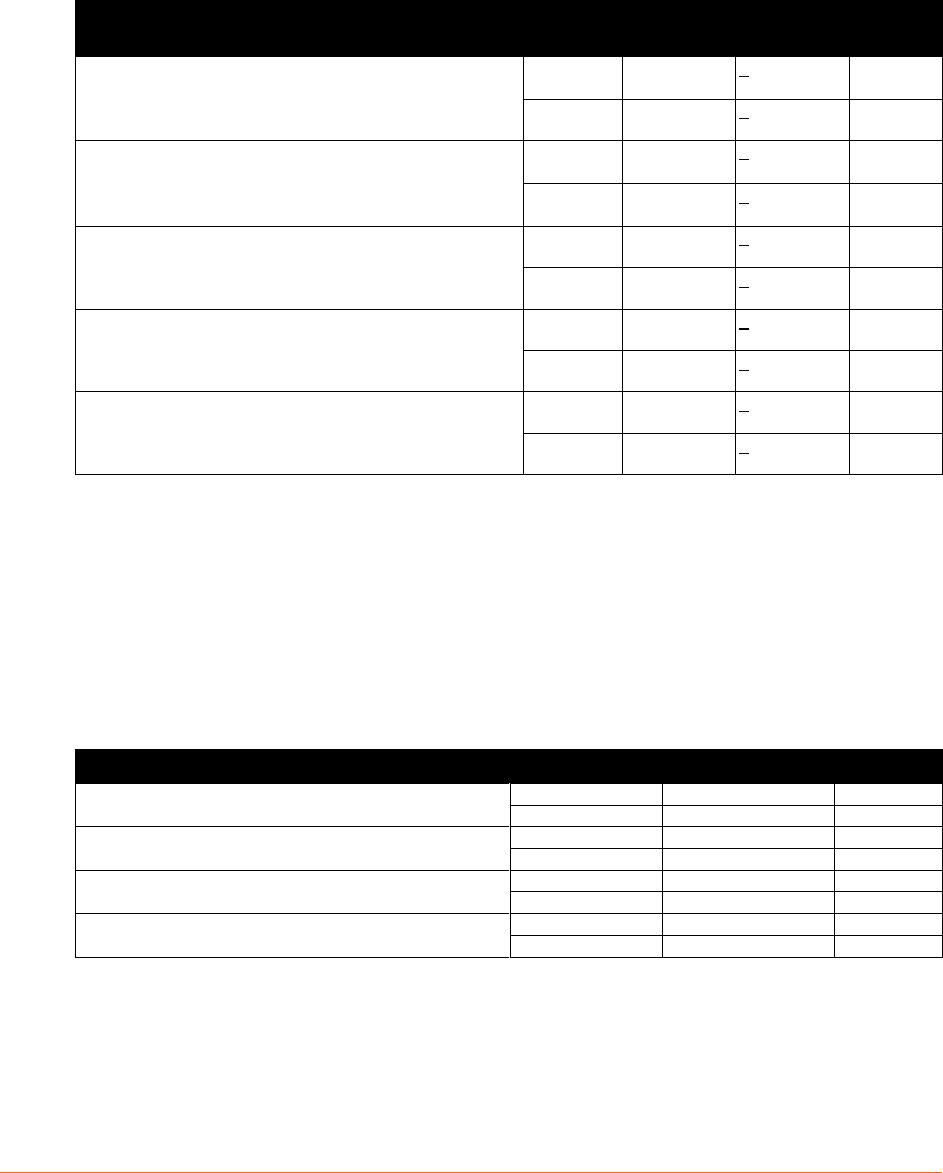
EVM
xPico 200 module TX EVM follow the IEEE specification listed in Table 7-6 below.
Table 7-6: xPico 200 Module Wi-Fi EVM
Characteristics
EVM Value MAX
Unit
RF Average Output EVM (11g)
6 Mbps
-5
dB
54 Mbps
-25
dB
RF Average Output EVM (11n 2.4Ghz)
MCS0
-5
dB
MCS7
-27
dB
RF Average Output EVM (11a)
6 Mbps
-5
dB
54 Mbps
-25
dB
RF Average Output EVM (11n 5Ghz)
MCS0
-5
dB
MCS7
-27
dB

xPico® 200 Series Wi-Fi® IoT Gateway module Data Sheet 25
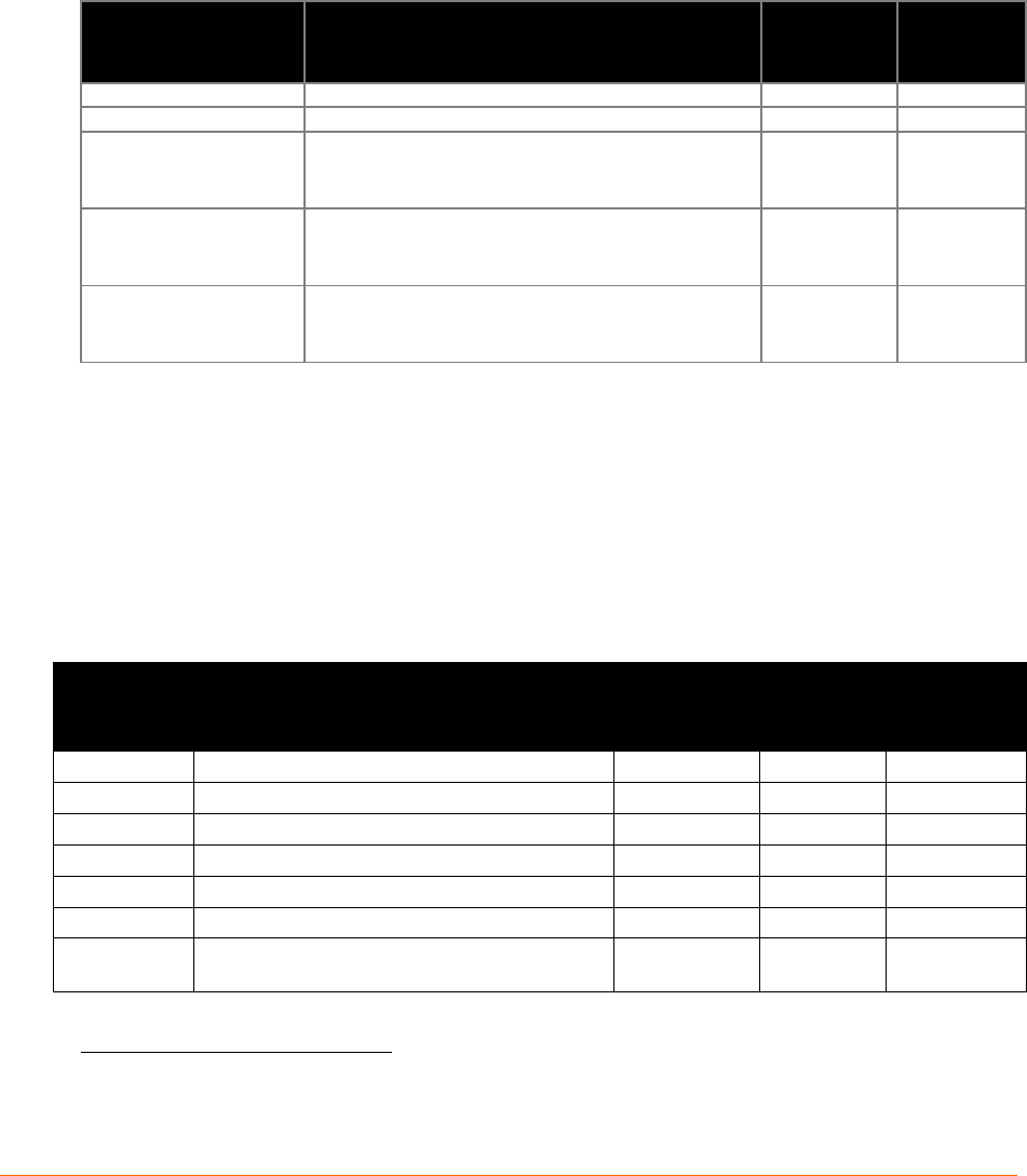
Receive Sensitivity
xPico 200 module Rx sensitivity is listed in Table 7-7 below.
Table 7-7: xPico 200 Module Rx Sensitivity
Receiver Characteristics
TYP.
MAX.
PER <8%, Rx Sensitivity @ 802.11b 1 Mbps
PER <8%, Rx Sensitivity @ 802.11b 11 Mbps
PER <10%, Rx Sensitivity @ 802.11g 6 Mbps
PER <10%, Rx Sensitivity @ 802.11g 54 Mbps
PER <10%, Rx Sensitivity @ 802.11n 2.4Ghz MCS0
PER <10%, Rx Sensitivity @ 802.11n 2.4Ghz MCS7
PER <10%, Rx Sensitivity @ 802.11a 6 Mbps
PER <10%, Rx Sensitivity @ 802.11a 54 Mbps
PER <10%, Rx Sensitivity @ 802.11n 5Ghz MCS0
PER <10%, Rx Sensitivity @ 802.11n 5Ghz MCS7
PER <10%, Rx Sensitivity @ 802.11ac MCS8 HT20
PER <10%, Rx Sensitivity @ 802.11ac MCS9 HT80
xPico® 200 Series Wi-Fi® IoT Gateway module Data Sheet 26
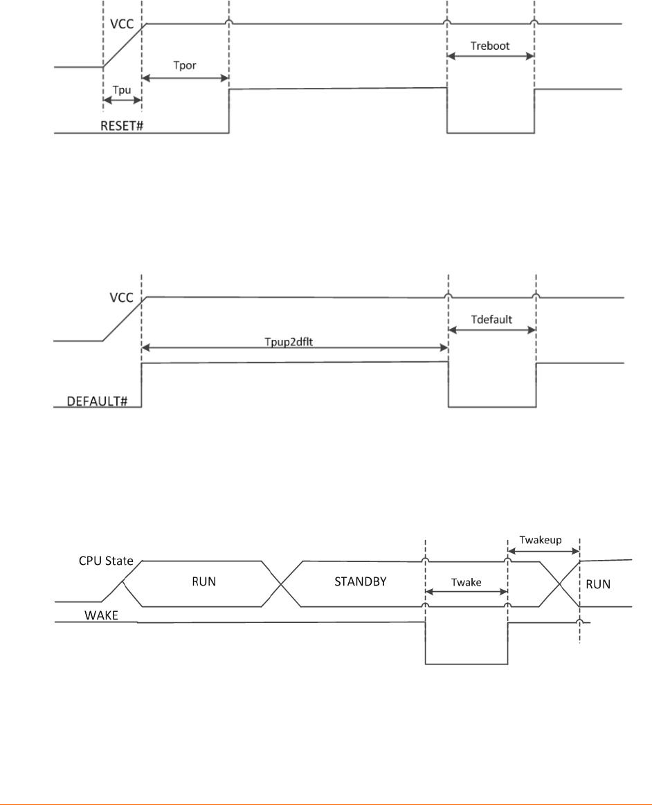
Power, Reset, Wake, Shutdown and Default Timing
The diagrams below show the timing requirement for VCC, RESET#, DEFAULT#, WAKE and
SHDN.
Figure 7-1 Reset Timing
Figure 7-2 Reset to Defaults Timing
Figure 7-3 Wake Timing

xPico® 200 Series Wi-Fi® IoT Gateway module Data Sheet 27
Table 7-8 Shutdown Pin Timing
Parameter
Description
Minimum
Maximum
Unit
Tpu
Time for VCC to reach 90% of its maximum
value
40
1000
us
Tpor
Time from VCC to reach 90% of its maximum
value and de-assertion of external reset.
50
ms
Treboot
Recommended reset pulse for system reboot
50
ms
Tpup2dflt
Time from VCC power up to DEFAULT#
assertion. Note DEFAULT# can be left floating
if unused.
0
ns
Tdefault
Assertion time for DEFAULT# to unit reset to
default and reboot.
6
S
Twake
Wake pulse width. Note wakeup is triggered on
the rising edge.
100
us
Teio_off
Time recommended to shut off external IO to
prevent leakage into module
0
ms
Memory
The xPico 200 module comes with the following memory profile:
Flash Memory
The xPico 200 module has 8MB serial NOR flash that is shared between the boot, OS, and user
space
SRAM
The xPico 200 module has 2MB SRAM
xPico® 200 Series Wi-Fi® IoT Gateway module Data Sheet 28
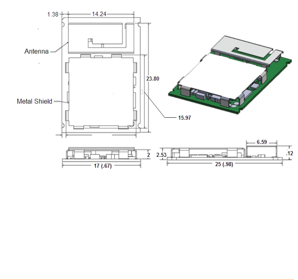
8: Package Description and Mechanical Footprint
The xPico 200 module comes in two different mechanical packages. The first is an SMT module
with an LGA footprint. The LGA footprint version is for SMT applications. The second
mechanical package is the xPico 200 module mounted on an edge card. The mechanical
dimensions for both options are shown below. Both mechanical packages also come with options
for two u.FL connectors for connection to external antennas or a single on-module antenna.
Note, Bluetooth is not available for the options with on-module antenna. The Edge Connector
version mates to TE Connectivity part number 2199230-4.
Dimensions
The size and thickness of the xPico 200 module is 25 mm (L) x 17 mm (W) x 2.53 mm (H) +/-
0.3 mm (including shielding). The PCB footprint is shown in the figure on the next page.
Figure 8-1 xPico 200 Enterprise Wi-Fi IoT Wi-Fi Module (Part 1 of 2)
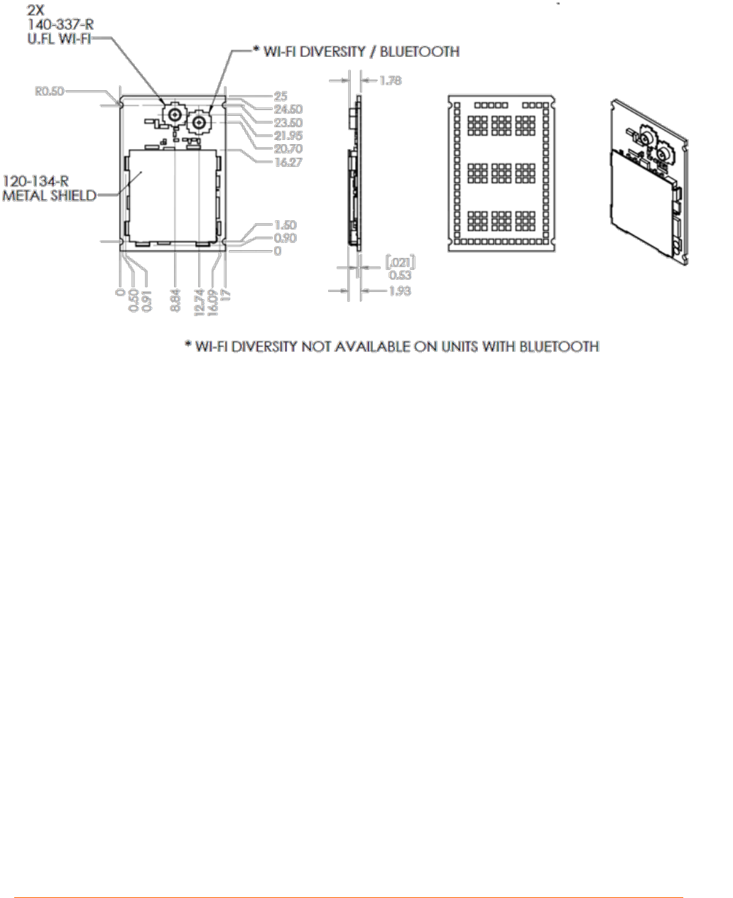
xPico® 200 Series Wi-Fi® IoT Gateway module Data Sheet 29
Figure 8-2 xPico 200 Enterprise Wi-Fi IoT Wi-Fi Module (Part 2 of 2)
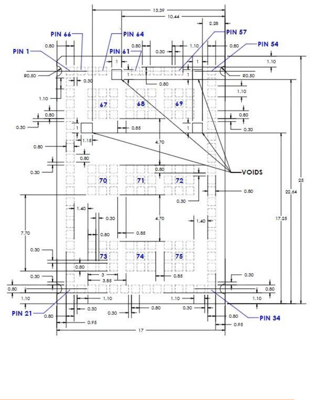
xPico® 200 Series Wi-Fi® IoT Gateway module Data Sheet 30
Figure 8-3 Layout Footprint for xPico 200
Enterprise Wi-Fi IoT Module
Note: It is recommended to follow the evaluation platform layout. The evaluation
platform CAD reference files are available upon request. Contact your local FAE or sales
account manager for access to the CAD package.
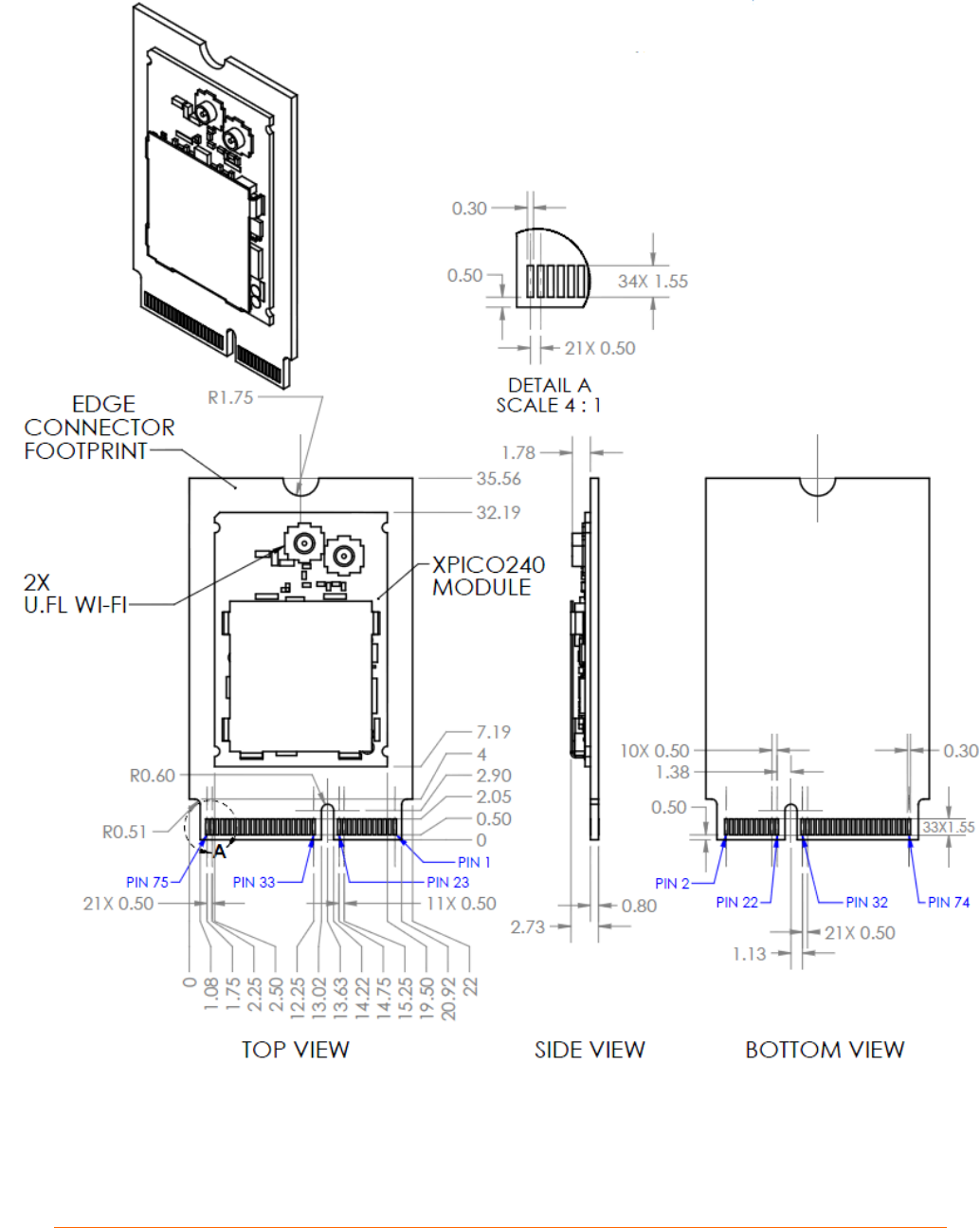
xPico® 200 Series Wi-Fi® IoT Gateway module Data Sheet 31
Figure 8-4 xPico 200 Edge Connector Module dimensions
Note: the Edge Connector Module mates to TE Connectivity part number 2199230-4.

xPico® 200 Series Wi-Fi® IoT Gateway module Data Sheet 32
Pin and Pad Definitions
Table 8-1 describes the xPico 200 Wi-Fi interface signal definitions as used in the modules.
The Signal Name column identifies the signal pin being described while the Primary Function
column provides definitions of the signal pin depending upon the member of the xPico 200
family being used. Differentiating the signal pins is beneficial when using multiple xPico 200
device types on a single platform.
Table 8-1: xPico 200 Interface Signal Definitions:
Signal Name
Primary Function
xPico 200 SMT
Pin
Edge Connector
Pin
Driver
Strength
GND
Signal Ground
1
1
SDCK
SDIO Clock
2
9
8mA
SDCMD
SDIO CMD
3
11
8mA
SDIO0
SDIO Data 0
4
13
8mA
SDIO1
SDIO Data 1
5
15
8mA
SDIO2
SDIO Data 2
6
17
8mA
SDIO3
SDIO Data 3
7
19
8mA
CP3/MISO
Configurable I/O- SPI MISO
8
46
8mA
CP4/MOSI
Configurable I/O-SPI MOSI
9
44
8mA
CP7/SCK
Configurable I/O-SPI Clock
10
42
8mA
CP8/CS
Configurable I/O-SPI Chip
Select
11
40
8mA
CP2/INT
Configurable I/O-SPI
interrupt input
12
48
8mA
CP15
Configurable I/O-I2CDATA2
13
56
8mA
CP16
Configurable I/O-I2CCLK2
14
54
8mA
CP5/I2CDATA
Configurable I/O-I2CDATA
15
58
8mA
CP6/I2CCLK
Configurable I/O-I2CCLK
16
60
8mA
WAKE
Toggle signal from low to
high to WAKE from SLEEP
or Power down state. This
pin must be pulled high with
a 100K ohm resistor.
Note: signal is noise
sensitive. Filter as close as
possible to module pin.
17
20
GND
Signal Ground
18
7
USB+
USB Device Port Positive
pin
19
3
USB-
USB Device Port Negative
pin
20
5
GND
Signal Ground
21
33
CP17/PWM/LED
Configurable I/O-PWM
22
16
8mA
RMII_TXD0
RMII TXD0 transmit output
23
73

xPico® 200 Series Wi-Fi® IoT Gateway module Data Sheet 33
Signal Name
Primary Function
xPico 200 SMT
Pin
Edge Connector
Pin
Driver
Strength
RMII_TXD1
RMII TXD1 transmit output
24
71
RMII_CLK
RMII interface clock
25
61
USB_H/DEV_SEL
USB Host/Device Mode
Select
Pull high for device mode
on USB
Pull low for host mode on
USB
Connect to ID pin of USB
connector
26
12
RMII_TXEN
RMII transmit enable output
27
67
RMII_RST
RMII reset output
28
70
SDIO_MODE
SDIO Master/Slave select
Pull high for master mode
on SDIO
Pull low for slave mode on
SDIO
29
14
RMII_RXDV
RMII RX data valid input
30
65
RMII_RXD0
RMII RXD0 receive input
31
55
RMII_RXD1
RMII RXD1 receive input
32
53
SYS_LED
System status LED, active
high
33
6
GND
Signal Ground
34
39
MDC
MDIO clock
35
47
MDIO
MDIO data
36
49
CP18/PWM
Configurable I/O-PWM
37
62
8mA
CP1
Configurable I/O
38
50
8mA
RESERVED1
Reserved for future UART
RX output
39
66
RESERVED2
Reserved for future UART
TX output
40
68
EXT_RESET#
Unit hardware reset, active
low. Drive low for 50ms to
reboot unit. Signal should
be driven high or pulled high
after assertion.
EXT_RESET# is inactive
during module power down
(standby) state. Assert
WAKE signal to come out of
low power states prior to
asserting reset.
41
52
CTS1
Serial clear-to-send input
42
36
8mA
VCC
Power input. Must be
connected to 3.3V power
supply
43
74

xPico® 200 Series Wi-Fi® IoT Gateway module Data Sheet 34
Signal Name
Primary Function
xPico 200 SMT
Pin
Edge Connector
Pin
Driver
Strength
VCC
Power input. Must be
connected to 3.3V power
supply
44
72
VCC
Power input. Must be
connected to 3,3V power
supply
45
2,4
RTS1
Serial ready-to-send (232) /
serial transmit enable (485)
output
46
34
8mA
RXD1
Serial receive data input
47
32
8mA
TXD1
Serial transmit data output
48
22
TMS
JTAG TMS Input
49
43
TCK
JTAG Clock Input
50
41
TDI
JTAG Data Input
51
37
TDO
JTAG Data Output
52
35
TRST
JTAG Reset Input
53
38
GND
Signal Ground
54
45
DEFAULT
Drive low for 6 seconds or
longer to reset unit to
default settings.
57
23
GND
Signal Ground
58
51
GND
Signal Ground
59
57
GND
Signal Ground
60
63
GND
Signal Ground
61
69
GND
Signal Ground
64
75
GND
Signal Ground
65
18
GND
Signal Ground
66
GND_PADS
Signal Ground
67,68,69,
70,71,72,
73,74,75
Note1: The current module supports an external 10/100Mbps Ethernet PHY via the RMII interface.
Note2: The logic IO pins are 3.3V tolerant.
Note3: SMT Pins 67 to 75 are the ground pads under the module. These pads must be connected to ground.
These pads also provide thermal relief for the module. It is recommended that multiple vias for each pad be used to
connect the ground pads to the ground plane. Please see the evaluation board layout as a reference for the ground
pad and multiple via in pad recommendation. Contact your local FAE or sales support for the evaluation kit artwork.
Note 4: All unused IO pins may be left floating, except for the required straps on pins 17, 26, and 29.
xPico® 200 Series Wi-Fi® IoT Gateway module Data Sheet 35
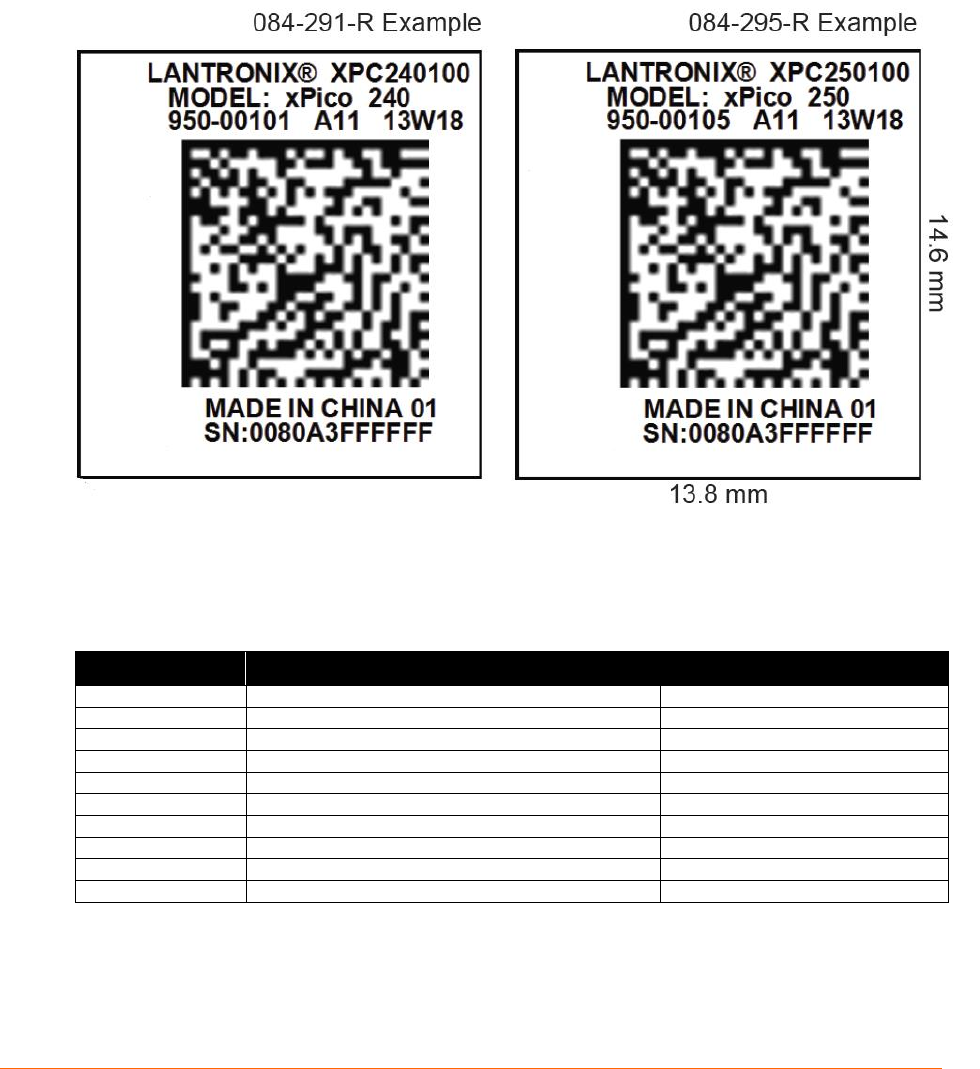
9: Product Information Label
The product information label contains important information about your specific module,
including the part number, revision, manufacturing date code, product model, country of origin,
datamatrix barcode, and MAC address.
Figure 9-1 xPico 200 Module Label
The xPico 200 module uses the Datamatrix ECC200 barcode standard. The field definitions are
as follows:
Table 9-1: Datamatrix ECC200 Barcode Standard Descriptions
Field
Description
Example
V1
Barcode format revision
1
C1
Field count.
6
P1
Part number of the module
R1
Revision of the module
A11
D1
Manufacturing datecode of the module
14W20
L1
Country and factory ID# of manufacturer
CHINA 03
S1
Serial number
0080A3980404
M1
MAC address
0080A3980404
M2
MAC address 2
0080A3980511
E1
End of barcode

xPico® 200 Series Wi-Fi® IoT Gateway module Data Sheet 36
10: Evaluation Kit
A xPico 200 module evaluation kit is available to provide a simple, quick and cost effective way to
evaluate the xPico 200 module. Use the evaluation kit to integrate the module into to your product
design and find out how simple, easy it is to get started.
The TBD_kit, is a single board with the xPico 200 module mounted.
The TBD_kit2 is a single board with the xPico 250 module mounted.
This allows the simple use of the module and use of the on-module antenna version. The
evaluation board includes the necessary keep out areas, so performance and positioning can be
evaluated.

xPico® 200 Series Wi-Fi® IoT Gateway module Data Sheet 37
11: Compliance (PLANNED)
DRAFT: All certs listed in this section are planned prior to the formal product release. The list is
subject to change based on final certification.
(According to ISO/IEC Guide and EN 45014)
Manufacturer's Name & Address:
Lantronix, Inc.
7535 Irvine Center Drive, Suite 100, Irvine, CA 92618 USA
Declares that the following product:
Product Name Model: xPico 200
Conforms to the following standards or other normative documents:
Table 11-1: Country Certifications (PLANNED)
Country
Specification
USA
FCC Part 15,Subpart B, Class B
FCC Part 15, Subpart C 15.247 (WLAN)
FCC Part 15, Subpart C 15.247 (BT)
FCC Part 15, Supbart E 15.407 (DFS)
Canada
ICES-003:2012 Issue 5, Class B
RSS-Gen, Issue 4, 2014-11
RSS-102, Issue 5, 2015-03
RSS-247, Issue 2, 2017-02
EU
See EU Declaration of Confirmity below.
Australia, New Zealand
N11206
AS/NZS 4268 2017
AS/NZS 2772.2
Japan
ARIB STD-T66(v3.7), MIC notice 88 Appendix 43 RCR STD-33 (v5.4), MIC
notice 88 Appendix 44
ARIB STD-T71(v6.1), MIC notice 88 Appendix 45
China SRRC
Planned
Safety
UL/CSA/EN/IEC 62368-R

xPico® 200 Series Wi-Fi® IoT Gateway module Data Sheet 38
Table 11-2: Country Transmitter IDs
Country
Specification
USA FCC ID
R68XPICO200 (Pending certification)
Canada IC ID
3867A-XPICO200 (Pending certification)
Japan ID
020-170133
China SRRC
TBD
Federal Communication Commission Interference Statement
This device complies with Part 15 of the FCC Rules. Operation is subject to the following two
conditions: (1) This device may not cause harmful interference, and (2) this device must accept
any interference received, including interference that may cause undesired operation.
This equipment has been tested and found to comply with the limits for a Class B digital device,
pursuant to Part 15 of the FCC Rules. These limits are designed to provide reasonable protection
against harmful interference in a residential installation. This equipment generates, uses, and can
radiate radio frequency energy and, if not installed and used in accordance with the instructions,
may cause harmful interference to radio communications. However, there is no guarantee that
interference will not occur in a particular installation. If this equipment does cause harmful
interference to radio or television reception, which can be determined by turning the equipment
off and on, the user is encouraged to try to correct the interference by one of the following
measures:
Reorient or relocate the receiving antenna.
Increase the separation between the equipment and receiver.
Connect the equipment into an outlet on a circuit different from that to which the receiver
is connected.
Consult the dealer or an experienced radio/TV technician for help.
FCC Caution: Any changes or modifications not expressly approved by the party responsible for
compliance could void the user's authority to operate this equipment.
This transmitter must not be co-located or operating in conjunction with any other antenna or
transmitter.
Operations in the 5.15-5.25GHz band are restricted to indoor usage only.
Radiation Exposure Statement:
This equipment complies with FCC radiation exposure limits set forth for an uncontrolled
environment. This equipment should be installed and operated with minimum distance 20cm
between the radiator & your body.

xPico® 200 Series Wi-Fi® IoT Gateway module Data Sheet 39
This device is intended only for OEM integrators under the following
conditions:
1) The antenna must be installed such that 20 cm is maintained between the antenna and users,
and
2) The transmitter module may not be co-located with any other transmitter or antenna.
As long as 2 conditions above are met, further transmitter test will not be required. However, the
OEM integrator is still responsible for testing their end-product for any additional compliance
requirements required with this module installed.
IMPORTANT NOTE: In the event that these conditions cannot be met (for example certain
laptop configurations or colocation with another transmitter), then the FCC authorization is no
longer considered valid and the FCC ID cannot be used on the final product. In these
circumstances, the OEM integrator will be responsible for re-evaluating the end product (including
the transmitter) and obtaining a separate FCC authorization.
End Product Labeling
This transmitter module is authorized only for use in device where the antenna may be installed
such that 20 cm may be maintained between the antenna and users. The final end product must
be labeled in a visible area with the following: “Contains FCC ID: R68XPICO200”. The grantee's
FCC ID can be used only when all FCC compliance requirements are met.
Manual Information To the End User
The OEM integrator has to be aware not to provide information to the end user regarding how to
install or remove this RF module in the user’s manual of the end product which integrates this
module.
The end user manual shall include all required regulatory information/warning as show in this
manual.
Industry Canada statement:
This device complies with RSS-247 of the Industry Canada Rules. Operation is subject to the
following two conditions: (1) This device may not cause harmful interference, and (2) this device
must accept any interference received, including interference that may cause undesired
operation.
Ce dispositif est conforme à la norme CNR-247 d'Industrie Canada applicable aux appareils radio
exempts de licence. Son fonctionnement est sujet aux deux conditions suivantes: (1) le dispositif
ne doit pas produire de brouillage préjudiciable, et (2) ce dispositif doit accepter tout brouillage
reçu, y compris un brouillage susceptible de provoquer un fonctionnement indésirable.
Radiation Exposure Statement:
This equipment complies with IC radiation exposure limits set forth for an uncontrolled
environment. This equipment should be installed and operated with minimum distance 20cm
between the radiator & your body.

xPico® 200 Series Wi-Fi® IoT Gateway module Data Sheet 40
Déclaration d'exposition aux radiations:
Cet équipement est conforme aux limites d'exposition aux rayonnements IC établies pour un
environnement non contrôlé. Cet équipement doit être installé et utilisé avec un minimum de 20
cm de distance entre la source de rayonnement et votre corps.
This device is intended only for OEM integrators under the following
conditions: (For module device use)
1) The antenna must be installed such that 20 cm is maintained between the antenna and users,
and
2) The transmitter module may not be co-located with any other transmitter or antenna.
As long as 2 conditions above are met, further transmitter test will not be required. However, the
OEM integrator is still responsible for testing their end-product for any additional compliance
requirements required with this module installed.
Cet appareil est conçu uniquement pour les intégrateurs OEM dans les
conditions suivantes: (Pour utilisation de dispositive module)
1) L'antenne doit être installée de telle sorte qu'une distance de 20 cm est respectée entre
l'antenne et les utilisateurs, et
2) Le module émetteur peut ne pas être coïmplanté avec un autre émetteur ou antenne.
Tant que les 2 conditions ci-dessus sont remplies, des essais supplémentaires sur l'émetteur ne
seront pas nécessaires. Toutefois, l'intégrateur OEM est toujours responsable des essais sur son
produit final pour toutes exigences de conformité supplémentaires requis pour ce module installé.
IMPORTANT NOTE:
In the event that these conditions can not be met (for example certain laptop
configurations or co-location with another transmitter), then the Canada authorization is
no longer considered valid and the IC ID can not be used on the final product. In these
circumstances, the OEM integrator will be responsible for re-evaluating the end product
(including the transmitter) and obtaining a separate Canada authorization.
NOTE IMPORTANTE:
Dans le cas où ces conditions ne peuvent être satisfaites (par exemple pour certaines
configurations d'ordinateur portable ou de certaines co-localisation avec un autre
émetteur), l'autorisation du Canada n'est plus considéré comme valide et l'ID IC ne peut
pas être utilisé sur le produit final. Dans ces circonstances, l'intégrateur OEM sera chargé
de réévaluer le produit final (y compris l'émetteur) et l'obtention d'une autorisation
distincte au Canada.
End Product Labeling
This transmitter module is authorized only for use in device where the antenna may be installed
such that 20 cm may be maintained between the antenna and users. The final end product must
be labeled in a visible area with the following: “Contains IC: 3867A-XPICO200”.
Plaque signalétique du produit final
Ce module émetteur est autorisé uniquement pour une utilisation dans un dispositif où l'antenne
peut être installée de telle sorte qu'une distance de 20cm peut être maintenue entre l'antenne et

xPico® 200 Series Wi-Fi® IoT Gateway module Data Sheet 41
les utilisateurs. Le produit final doit être étiqueté dans un endroit visible avec l'inscription
suivante: "Contient des IC: 3867A-XPICO200".
Manual Information To the End User
The OEM integrator has to be aware not to provide information to the end user regarding how to
install or remove this RF module in the user’s manual of the end product which integrates this
module.
The end user manual shall include all required regulatory information/warning as show in this
manual.
Manuel d'information à l'utilisateur final
L'intégrateur OEM doit être conscient de ne pas fournir des informations à l'utilisateur final quant
à la façon d'installer ou de supprimer ce module RF dans le manuel de l'utilisateur du produit final
qui intègre ce module.
Le manuel de l'utilisateur final doit inclure toutes les informations réglementaires requises et
avertissements comme indiqué dans ce manuel.
Caution :
(i) the device for operation in the band 5150-5250 MHz is only for indoor use to reduce
the potential for harmful interference to cochannel mobile satellite systems;
(ii) the maximum antenna gain permitted for devices in the bands 5250-5350 MHz and
5470-5725 MHz shall be such that the equipment still complies with the e.i.r.p. limit;
(iii) the maximum antenna gain permitted for devices in the band 5725-5850 MHz shall be
such that the equipment still complies with the e.i.r.p. limits specified for point-to-point
and non-point-to-point operation as appropriate; and
(iv) Users should also be advised that high-power radars are allocated as primary users
(i.e. priority users) of the bands 5250-5350 MHz and 5650-5850 MHz and that these
radars could cause interference and/or damage to LE-LAN devices.
Avertissement:
Le guide d’utilisation des dispositifs pour réseaux locaux doit inclure des instructions précises sur
les restrictions susmentionnées, notamment :
(i) les dispositifs fonctionnant dans la bande 5150-5250 MHz sont réservés uniquement pour une
utilisation à l’intérieur afin de réduire les risques de brouillage préjudiciable aux systèmes de
satellites mobiles utilisant les mêmes canaux;
(ii) le gain maximal d'antenne permis pour les dispositifs utilisant les bandes de 5250 à 5 350
MHz et de 5470 à 5725 MHz doit être conforme à la limite de la p.i.r.e;
(iii) le gain maximal d'antenne permis (pour les dispositifs utilisant la bande de 5 725 à 5 850
MHz) doit être conforme à la limite de la p.i.r.e. spécifiée pour l'exploitation point à point et
l’exploitation non point à point, selon le cas;
(iv) De plus, les utilisateurs devraient aussi être avisés que les utilisateurs de radars de haute
puissance sont désignés utilisateurs principaux (c.-à-d., qu’ils ont la priorité) pour les bandes
5250-5350 MHz et 5650-5850 MHz et que ces radars pourraient causer du brouillage et/ou des
dommages aux dispositifs LAN-EL.
xPico® 200 Series Wi-Fi® IoT Gateway module Data Sheet 42
7535 Irvine Center Drive, Suite 100, Irvine, CA 92618
EU DECLARATION OF CONFORMITY
This declaration of conformity is issued under the sole responsibility of the manufacturer.
Object of the declaration
Product Information
Product Name: xPico 200
Model
SW Version
(Radio FW)
HW Version
xPico 240
7.15.168.87
11 (or later)
xPico 250
7.15.168.87
11 (or later)
The object of the declaration described above is in conformity with the relevant Union
harmonisation legislation:
• References to the relevant harmonised standards used or references to the technical
specifications in relation to which conformity is declared
Radio Equipment Directive 2014/53/EU
EN 300 328 V2.1.1
EN 301 489-1 V2.1.1
EN 301 489-17 V3.1.1
EN 301 893-1 V2.1.1
EN 62311:2008
62368-1
The notified body, ___________________________, performed a conformity assessment of the technical
construction file and issued certificate _________________________.
Signature: ________________________________ Date: ___________________________
Name: Daryl R. Miller
Title: VP of Engineering, Lantronix, Inc.

xPico® 200 Series Wi-Fi® IoT Gateway module Data Sheet 43
Table 11-3: Europe – EU Declaration of Conformity
Česky [Czech]
Lantronix tímto prohlašuje, že tento xPico 200 je ve shodě se základními
požadavky a dalšími příslušnými ustanoveními směrnice 2014/53/EU.
Dansk [Danish]
Undertegnede Lantronix erklærer herved, at følgende udstyr xPico 200 overholder
de væsentlige krav og øvrige relevante krav i direktiv 2014/53/EU.
Deutsch [German]
Hiermit erklärt Lantronix, dass sich das Gerät xPico 200 in Übereinstimmung mit
den grundlegenden Anforderungen und den übrigen einschlägigen Bestimmungen
der Richtlinie 2014/53/EU befindet.
Eesti [Estonian]
Käesolevaga kinnitab Lantronix seadme xPico 200 vastavust direktiivi 2014/53/EU
põhinõuetele ja nimetatud direktiivist tulenevatele teistele asjakohastele sätetele.
English
Hereby, Lantronix, declares that this xPico 200 is in compliance with the essential
requirements and other relevant provisions of Directive 1999/5/EC.
Español [Spanish]
Por medio de la presente Lantronix declara que el xPico 200 module cumple con
los requisitos esenciales y cualesquiera otras disposiciones aplicables o exigibles
de la Directiva 2014/53/EU.
Ελληνική [Greek]
ΜΕ ΤΗΝ ΠΑΡΟΥΣΑ Lantronix ΔΗΛΩΝΕΙ ΟΤΙ xPico 200 ΣΥΜΜΟΡΦΩΝΕΤΑΙ ΠΡΟΣ
ΤΙΣ ΟΥΣΙΩΔΕΙΣ ΑΠΑΙΤΗΣΕΙΣ ΚΑΙ ΤΙΣ ΛΟΙΠΕΣ ΣΧΕΤΙΚΕΣ ΔΙΑΤΑΞΕΙΣ ΤΗΣ
ΟΔΗΓΙΑΣ 2014/53/EU.
Français [French]
Par la présente Lantronix déclare que l'appareil xPico 200 est conforme aux
exigences essentielles et aux autres dispositions pertinentes de la directive
2014/53/EU.
Italiano [Italian]
Con la presente Lantronix dichiara che questo xPico 200 è conforme ai requisiti
essenziali ed alle altre disposizioni pertinenti stabilite dalla direttiva 2014/53/EU.
Latviski [Latvian]
Ar šo Lantronix deklarē, ka xPico 200 atbilst Direktīvas 2014/53/EU būtiskajām
prasībām un citiem ar to saistītajiem noteikumiem.
Lietuvių [Lithuanian]
Šiuo Lantronix deklaruoja, kad šis xPico 200 atitinka esminius reikalavimus ir kitas
2014/53/EU Direktyvos nuostatas.
Nederlands [Dutch]
Hierbij verklaart Lantronix dat het toestel xPico 200 overeenstemming is met de
essentiële eisen en de andere relevante bepalingen van richtlijn 2014/53/EU.
Malti [Maltese]
Hawnhekk, Lantronix, jiddikjara li dan xPico 200 jikkonforma malħtiġijiet essenzjali
u ma provvedimenti oħrajn relevanti li hemm fid-Dirrettiva 1999/5/EC.
Magyar [Hungarian]
Alulírott, Lantronix nyilatkozom, hogy a xPico 200 megfelel a vonatkozó alapvetõ
követelményeknek és az 2014/53/EU irányelv egyéb elõírásainak.
Polski [Polish]
Niniejszym Lantronix oświadcza, że xPico 200 jest zgodny z zasadniczymi
wymogami oraz pozostałymi stosownymi postanowieniami Dyrektywy 2014/53/EU.
Português
[Portuguese]
Lantronix declara que este xPico 200 está conforme com os requisitos essenciais
e outras disposições da Directiva 2014/53/EU.
Slovensko [Slovenian]
Lantronix izjavlja, da je ta xPico 200 v skladu z bistvenimi zahtevami in ostalimi
relevantnimi določili direktive 2014/53/EU.
Slovensky [Slovak]
Lantronix týmto vyhlasuje, že xPico 200 enterprise Wi-Fi IoT module spĺňa
základné požiadavky a všetky príslušné ustanovenia Smernice 2014/53/EU.
Suomi [Finnish]
Lantronix vakuuttaa täten että xPico 200 tyyppinen laite on direktiivin 2014/53/EU
oleellisten vaatimusten ja sitä koskevien direktiivin muiden ehtojen mukainen.
Svenska [Swedish]
Härmed intygar Lantronix att denna xPico 200 står I överensstämmelse med de
väsentliga egenskapskrav och övriga relevanta bestämmelser som framgår av
direktiv 2014/53/EU.
查詢 NB no.
http://ec.europa.eu/enterprise/newapproach/nando/index.cfm?fuseaction=notifiedbody.main
cs
da
de
et
en
es
el
fr
it
nl
mt
hu
pl
pt
sl
fi
sv

xPico® 200 Series Wi-Fi® IoT Gateway module Data Sheet 44
Table 11-4: Approved External Antenna(s) List
Antenna Type
Peak Gain
Typical
Lantronix
Part
Number
Vendor
Vendor Part
Number
Approved
Region
PCB Strip Antenna
with 50 mm cable to
U.FL connector
With tape backing
2.5dBi, 2.39 Ghz
to 2.49 Ghz
5dBi, 4.9Ghz to
5.9Ghz
XPW100A0
03-01-B
50 piece
bulk pack
Ethertronics®
1001077
FCC, IC, EU,
AUS/NZS,
JPN, China,
PCB Strip Antenna
with 50 mm cable to
U.FL connector
Without tape
backing
2.5dBi, 2.39 Ghz
to 2.49 Ghz
5dBi, 4.9Ghz to
5.9Ghz
Ethertronics
1000668
FCC, IC, EU,
AUS/NZS,
JPN, China,
Swivel type antenna,
with RP-SMA(M)
connector
2 dBi, 2.4 Ghz to
2.5 Ghz, 2 dBi,
5.15 Ghz to 5.85
Ghz
930-033-R-
ACC
50 piece
bulk pack
Wanshih
WSS002
FCC, IC, EU,
AUS/NZS,
JPN, China,
Swivel type antenna,
with RP-SMA(M)
connector
3.8 dBi, 2.4Ghz to
2.5Ghz,
5.5 dBi, 4.9 Ghz to
5.8Ghz
Taoglas
GW.71.5153
(Not for EU
use)
FCC, IC,
AUS/NZS,
JPN, China,
Manufacturer's Contact:
Lantronix, Inc.
7535 Irvine Center Drive
Suite 100
Irvine, CA 92618 USA
Tel: 949-453-3990
Fax: 949-453-3995
RoHS, REACH, and WEEE Compliance Statement
Please visit http://www.lantronix.com/legal/rohs/ for Lantronix’s statement about RoHS,
REACH and WEEE compliance.

xPico® 200 Series Wi-Fi® IoT Gateway module Data Sheet 45
12: Ordering Information
Table 12-1: xPico 200 Series Order Information
Part Number
Description
XPC240100B
Pico 240 Emb GW, Wi-Fi, Eth, Dual u.fl, LGA, BULK
XPC240200B
xPico 240 Emb GW, Wi-Fi, Eth, Module Ant, LGA, BULK
XPC240300B
xPico 240 Emb GW, Wi-Fi, Eth, Dual u.fl, Edge, BULK
XPC240300K
xPico 240 Evaluation Kit with Edge Connector Module
XPC250100B
xPico 250 Emb GW, Wi-Fi, Eth, BT, Dual u. fl, LGA, BULK
XPC250300B
xPico Emb GW, Wi-Fi, Eth, BT, Dual u. fl, Edge, BULK
XPC250300K
xPico 250 Evaluation Kit with Edge Connector Module
Contact Information
For details contact your local Lantronix representative or Lantronix directly:
Asia Pacific Region via e-mail at asiapacific_sales@lantronix.com
Europe via e-mail at eu_sales@lantronix.com
Japan via e-mail at japan_sales@lantronix.com
United States via e-mail at sales@lantronix.com or call OEM sales support at
800-526-8764.
Warranty
The xPico 200 module comes with an industry best 5-year warranty. For more details on the
Lantronix warranty replacement policy, please go to our web site at
www.lantronix.com/support/warranty.
© 2017 Lantronix, Inc. All rights reserved. No part of the contents of this book may be transmitted or reproduced in any form or by any
means without the written permission of Lantronix. Lantronix and xPico are registered trademarks of Lantronix, Inc. in the United States
and other countries. Patented: http://patents.lantronix.com; additional patents pending.