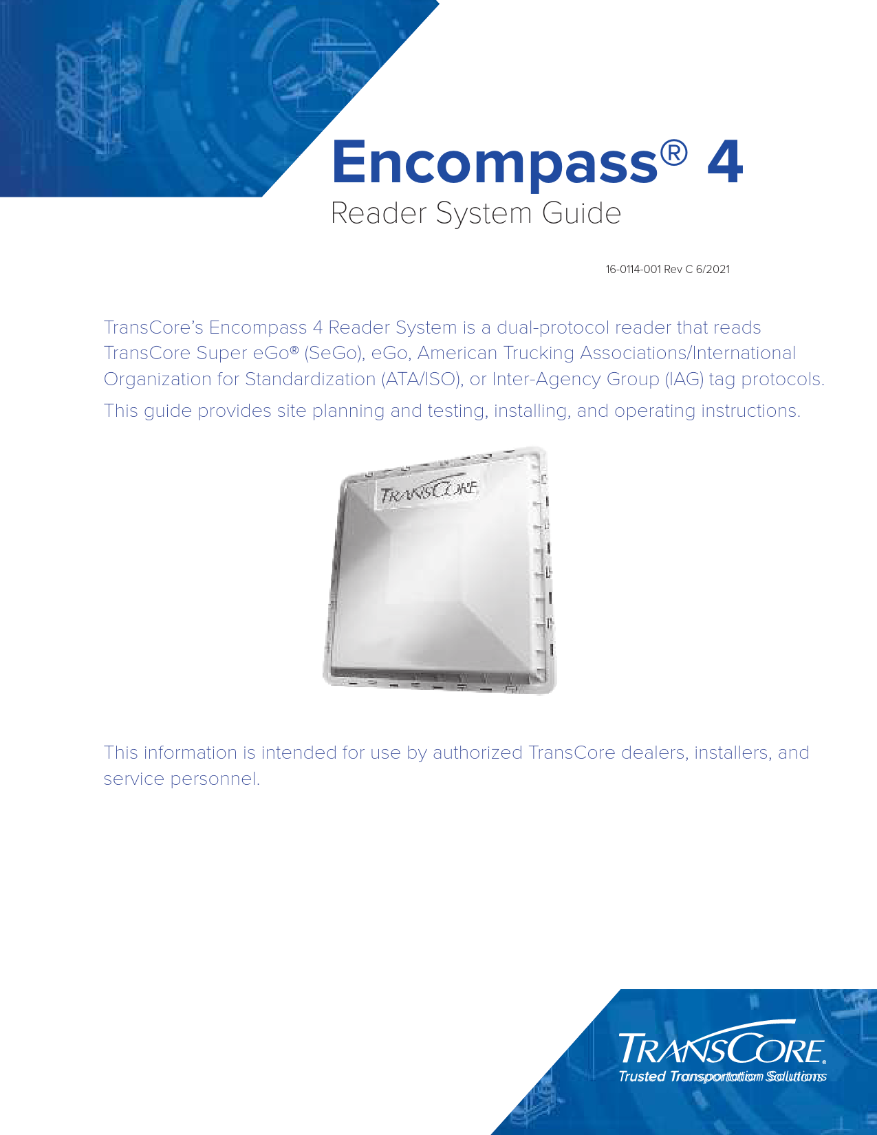
User Guide for TRANSCORE models including: E4PT90V45, FIHE4PT90V45, 10-4002-002 Encompass 4 RFID Reader, Encompass 4 RFID Reader
TransCore E4PT90V45 Location and Monitoring Service Interrogator FIHE4PT90V45 FIHE4PT90V45 e4pt90v45
Encompass® 4 Reader System Guide 16-0114-001 Rev C 6/2021 TransCore's Encompass 4 Reader System is a dual-protocol reader that reads TransCore Super eGo® (SeGo), eGo, American Trucking Associations/International Organization for Standardization (ATA/ISO), or Inter-Agency Group (IAG) tag protocols. This guide provides site planning and testing, installing, and operating instructions. This information is intended for use by authorized TransCore dealers, installers, and service personnel. Trusted Transportation Solutions Encompass 4 Reader System Guide © 2009-2021 TransCore, LP. All rights reserved. TRANSCORE, AMTECH, EGO, and ENCOMPASS are registered trademarks and are used under license. All other trademarks are the property of their respective owners. Contents are subject to change. Printed in the U.S.A. Information in this document is subject to change and does not represent a commitment on the part of TransCore, LP. For further information, contact: TransCore 8600 Jefferson Street NE Albuquerque, New Mexico 87113 USA TransCore Technical Support Web: www.transcore.com Phone: (505) 856-8007 ii TransCore Proprietary WARNING TO USERS IN THE UNITED STATES FEDERAL COMMUNICATIONS COMMISSION (FCC) LOCATION AND MONITORING SERVICE STATEMENT 47 CFR §90.351 NOTE: The user is required to obtain a Part 90 site license from the Federal Communications Commission (FCC) to operate this radio frequency identification (RFID) device in the United States. The FCC ID number is FIHE4PT90V45. Access the FCC website at www.fcc.gov to obtain additional information concerning licensing requirements. NOTE: Users in all countries should check with the appropriate local authorities for licensing requirements. FCC RADIO FREQUENCY INTERFERENCE STATEMENT 47 CFR §15.105(A) NOTE: This equipment has been tested and found to comply with the limits for a Class A digital device pursuant to Part 15 of the FCC rules. These limits are designed to provide reasonable protection against harmful interference when the equipment is operated in a commercial environment. This equipment generates, uses, and can radiate RF energy and may cause harmful interference to radio communications if not installed and used in accordance with the instruction manual. Operating this equipment in a residential area is likely to cause harmful interference, in which case, depending on the laws in effect, the user may be required to correct the interference at their own expense. NO UNAUTHORIZED MODIFICATIONS 47 CFR §15.21 CAUTION: This equipment may not be modified, altered, or changed in any way without permission. Unauthorized modification may void the equipment authorization from the FCC and will void the warranty. USE OF SHIELDED CABLES AND GROUNDING 47 CFR §15.27(A) NOTE: Shielded cables and earth grounding the unit is recommended for this equipment to comply with FCC regulations. TRANSCORE, LP USA TransCore Proprietary iii Encompass 4 Reader System Guide AVERTISSEMENT À L'ATTENTION DES UTILISATEURS AUX ÉTATS-UNIS DÉCLARATION 47 CFR §90.351 (CODE DES RÈGLEMENTS FÉDÉRAUX) DE LA FEDERAL COMMUNICATIONS COMMISSION (FCC) SUR LES SERVICES DE LOCALISATION ET DE CONTRÔLE REMARQUE : L'utilisateur est tenu d'obtenir une licence d'utilisation sur site Partie 90 auprès de la Federal Communications Commission (FCC) afin de pouvoir utiliser ce dispositif RFID (radioidentification) aux États-Unis ou au Canada. Le numéro d'identification de la FCC est FIHE4PT90V45. Pour obtenir de plus amples informations concernant les exigences relatives aux licences, prière de consulter le site web de la FCC à www.fcc.gov. REMARQUE : Il est recommandé à tous les utilisateurs, quel que soit leur pays, de consulter les autorités locales compétentes sur les exigences de licence. DÉCLARATION 47 CFR §15.105(A) DE LA FCC SUR LES INTERFÉRENCES DES FRÉQUENCES RADIO REMARQUE : Cet appareil a été testé et déclaré conforme à la catégorie d'un appareil numérique de classe A en accord avec la partie 15 des directives de la FCC. Ces normes visent à assurer une protection raisonnable contre les interférences nuisibles lorsque l'appareil est utilisé dans un environnement commercial. Cet appareil génère, utilise et peut émettre de l'énergie RF et peut être à l'origine d'interférences nuisibles aux communications radio s'il n'est pas installé et utilisé en suivant les directives du manuel d'instructions. Si cet appareil est utilisé dans une zone résidentielle, il est probable qu'il cause des interférences nuisibles. Dans ce cas, l'utilisateur pourrait être amené à remédier aux interférences à ses propres frais, selon les lois du pays en vigueur. AUCUNE MODIFICATION NON AUTORISÉE 47 CFR §15.21 MISE EN GARDE : Il est interdit de modifier, d'altérer ou d'apporter des changements à cet appareil de quelque manière que ce soit sans autorisation. Toute modification non autorisée peut annuler l'autorisation d'utilisation accordée par la FCC et annulera la garantie. UTILISATION DE CÂBLES BLINDÉS ET MISE À LA TERRE 47 CFR §15.27(A) REMARQUE : Il est recommandé d'utiliser des câbles blindés et une mise à la terre avec cet appareil afin de répondre aux réglementations de la FCC TRANSCORE, LP ÉTATS-UNIS iv TransCore Proprietary WARNING TO USERS IN CANADA INDUSTRY CANADA (IC) INDUSTRY CANADA'S RADIO STANDARD SPECIFICATIONS (RSS-137) LOCATION AND MONITORING SERVICE IN THE BAND 902-928 MHZ SECTION 2.1 NOTE: The user is required to obtain a license from Industry Canada (IC), to operate this radio frequency identification (RFID) device in Canada. The IC ID number is 1584A-E4RSS137V45 access the IC website at www.ic.gc.ca to obtain additional information concerning licensing requirements. Industry Canada (IC) Industry Canada's Radio Standard Specifications General Requirements (RSS-GEN) for Compliance of Radio Apparatus Statement Section 8.4 This device complies with Industry Canada's license-exempt RSSs. Operation is subject to the following two conditions: 1 ) This device may not cause interference; and 2 ) This device must accept any interference, including interference that may cause undesired operation of the device. AVERTISSEMENT AUX UTILISATEURS AU CANADA INDUSTRIE CANADA (IC) INDUSTRIE CANADA RADIO STANDARD SPECIFICATIONS (CNR-137) EMPLACEMENT ET SERVICE DE SURVEILLANCE DANS LA BANDE 902-928 MHZ, SECTION 2.1 Remarque : L'utilisateur est tenu d'obtenir une licence d'Industrie Canada (IC), afin d'exploiter ce dispositif d'identification par radiofréquence au Canada. Le numéro d'identification d'IC est 1584A-E4RSS137V45. Pour obtenir de plus amples informations concernant les exigences relatives aux licences, prière de consulter le site web de d'IC à www.ic.gc.ca . Radio Standard Spécifications exigences générales Industrie Canada (IC) Industrie Canada (CNRGEN) pour s'acquitter du Radio appareil déclaration article 8.4 Le présent appareil est conforme aux CNR d'Industrie Canada applicables aux appareils radio exempts de licence. L'exploitation est autorisée aux deux conditions suivantes : 1 ) l'appareil ne doit pas produire de brouillage, et 2 ) l'utilisateur de l'appareil doit accepter tout brouillage radioélectrique subi, même si le brouillage est susceptible d'en compromettre le fonctionnement. TransCore Proprietary v Encompass 4 Reader System Guide RADIO FREQUENCY HEALTH LIMITS FOR ENCOMPASS 4 READER USING AN EXTERNAL ANTENNA IN FREQUENCY BAND OF 902.25 TO 903.75 AND 910.00 TO 921.50 MHZ Several agencies (OSHA, FCC, IC) have environmental guidelines regulating maximum permissible exposure (MPE) or "safe" exposure levels that this product falls under. To ensure that proper safety guideline for the end users of this product, i.e. Occupational (Controlled) and General Population/Public (Uncontrolled), the recommended levels for each of the agencies are presented in the next sections with TransCore's recommendations for safety in the last section. OSHA (Occupational Safety and Health Administration) OSHA (an agency of The United States of America) legislates in the Code of Federal Regulations (CFR) Title 29 Part 1910 Subpart G 1910.97 titled "Nonionizing radiation", a maximum safe exposure limit of 10 milliwatts per square centimeter (mW/cm2) during any 0.1-hour period (i.e. 6 minutes). Using the frequency (in the middle of the band of operation of this equipment) of 915 MHz and the highest antenna gain that this equipment is certified for use in a final installation, the minimum safe distance was calculated to be 7.7 in (19.5 cm). FCC (Federal Communication Commission) FCC (an agency of The United States of America) legislates in the Code of Federal Regulations (CFR) Title 47 Chapter I Subchapter A Part 1 Subpart I Section 1.1310 titled "Radiofrequency radiation exposure limits" that the maximum permissible exposure (MPE) is the following: Occupational/Controlled Exposure Power density = frequency (in MHz)/300 mW/cm2 with an Averaging time of 6 Min General Population/Uncontrolled Exposure Power density = frequency (in MHz)/1500 mW/cm2 with an Averaging time of 30 Min Using the frequency (in the middle of the band of operation of this equipment) of 915MHz and the highest antenna gain that this equipment is certified for use in a final installation, the minimum safe distance was calculated. The MPE minimum distances are 13.9 in (35.4 cm) for the Occupational/ Controlled environment, and 31.1 in (79.1 cm) for the General Population/Uncontrolled environment. Industry Canada (Innovation, Science and Economic Development Canada) Industry Canada (a Department of the Government of Canada) sets out the requirements in Radio Standards Specification RSS-102, Issue 5 guidelines, recommending a maximum safe power density in W/m2. Thus, the maximum permissible exposure for general population/uncontrolled exposure at 915 MHz is 8.77 W/m2. The average time is 6 minutes. The maximum permissible exposure (MPE) is the following: vi TransCore Proprietary Controlled Environment Power density = 0.6455*frequency (in MHz)0.5 W/m2 with a Reference Period time of 6 Min General Public/Uncontrolled Environment Power density = 0.02619*frequency (in MHz)0.6834 W/m2 with a Reference Period time of 6 Min Using the frequency (in the middle of the band of operation of this equipment) of 915MHz and the highest antenna gain that this equipment is certified for use in a final installation, the minimum safe distance was calculated. The MPE minimum distances are 15.6 in (39.5 cm) for the Controlled environment and 26 in (66 cm) for the General Public/Uncontrolled environment. TransCore Recommendation on MPE (Maximum Permissible Exposure) The calculated power densities and MPE distance for each of the agencies respective to the environment is shown below. Agency OSHA FCC IC Occupational/Controlled Environment Power Density (mW/cm2) 10 3.05 2.43 MPE minimum distance in cm 7.7 19.5 13.9 35.4 15.6 39.5 Time (min) 6 6 6 General Population/Public/Uncontrolled Environment Agency OSHA Power Density (mW/cm2) 10 MPE minimum distance In cm 7.7 19.5 Time (min) 6 FCC 0.61 31.1 79.1 30 IC 0.877 26.0 66.0 6 With the equipment installed and running at the maximum transmit power of 2.0W (33 dBm), 0dB transmit attenuation, using the highest gain antenna that the equipment is certified for, the recommendation for each of the operation environments is as follows: 1 ) The antenna should be installed at least 31.1 in (79.1 cm) from the General Population/Public i.e. Uncontrolled Environment. 2 ) Maintenance personnel (i.e. Occupational/Controlled Environment) must remain at least 16 in (40 cm) from the antenna and limit their time in the environment to 6 minutes when the system is operating. TransCore Proprietary vii Encompass 4 Reader System Guide LIMITES D'EXPOSITION AUX RADIOFRÉQUENCES POUR LE LECTEUR ENCOMPASS 4 UTILISANT UNE ANTENNE EXTERNE SUR LA BANDE DE FRÉQUENCES DE 902.25 À 903.75 ET DE 910.00 À 921.50 MHZ Plusieurs organismes (OSHA, FCC, IC) publient des directives environnementales qui recommandent des limites d'exposition maximale autorisée (normes MPE) ou des niveaux d'exposition « sûrs » auxquels cet appareil se conforme. Pour faire en sorte que chaque utilisateur final ait connaissance des directives de sécurité qui le concerne, que ce soit dans son travail (accès contrôlé) ou pour la population générale/le grand public (accès non contrôlé), TransCore présente les niveaux recommandés par chaque organisme dans ses recommandations sécuritaires détaillées dans la dernière section. OSHA (Occupational Safety and Health Administration) Dans le Code des réglementations fédérales (CFR), Titre 29, Partie 1910, Sous-partie G 1910.97, intitulée « Nonionizing radiation » (Rayonnements non ionisants), l'OSHA (organisme américain) recommande un plafond d'exposition maximale de 10 milliwatts par centimètre carré (mW/cm2) pendant une période de 0,1 heure (soit 6 minutes). En utilisant la fréquence de 915 MHz (milieu de la bande de fréquences de cet appareil) et le gain d'antenne maximal pour lequel cet appareil a reçu une certification d'utilisation dans une installation finale, la distance minimale sécuritaire est de 19,5 cm (7,7 po). FCC (Federal Communication Commission) Dans le Code des réglementations fédérales (CFR), Titre 47, Chapitre I, Sous-chapitre A, Partie 1, Sous-partie I, Section 1.1310 intitulée « Radiofrequency radiation exposure limits » (Limites d'exposition aux rayonnements de radiofréquence), la FCC (organisme américain) établit les limites d'exposition maximale autorisée (normes MPE) comme suit : Exposition professionnelle/contrôlée Densité de puissance = fréquence (en MHz)/300 mW/cm2 avec une durée moyenne de 6 min. Exposition de la population générale/non contrôlée Densité de puissance = fréquence (en MHz)/1500 mW/cm2 avec une durée moyenne de 30 min. En utilisant la fréquence de 915 MHz (milieu de la bande de fréquences de cet appareil) et le gain d'antenne maximal pour lequel cet appareil a reçu une certification d'utilisation dans une installation finale, la distance minimale sécuritaire est la suivante : les distances MPE minimales sont de 35,4 cm (13,9 po) pour l'environnement professionnel/contrôlé et de 79,1 cm (31,1 po) pour la population générale/environnement non contrôlé. viii TransCore Proprietary Industrie Canada (Innovation, Sciences et Développement économique Canada) Le Cahier des charges sur les normes radioélectriques 102, 5e édition, d'Industrie Canada (un ministère du Gouvernement du Canada) établit des recommandations pour une densité de puissance maximale sécuritaire en W/m2. Ainsi, l'exposition maximale admissible pour la population générale/non contrôlée à 915 MHz est calculée à 8,77 W/m2. La durée moyenne est de 6 minutes. Les limites d'exposition maximale autorisée (normes MPE) sont les suivantes : Environnement contrôlé Densité de puissance = 0,6455*fréquence (en MHz)0,5 W/m2 avec une durée de référence de 6 min. Grand public/environnement non contrôlé Densité de puissance = 0,02619*fréquence (en MHz)0,6834 W/m2 avec une durée de référence de 6 min. En utilisant la fréquence de 915 MHz (milieu de la bande de fréquences de cet appareil) et le gain d'antenne maximal pour lequel cet appareil a reçu une certification d'utilisation dans une installation finale, la distance minimale sécuritaire est la suivante : les distances MPE minimales sont de 39,5 cm (15,6 po) pour l'environnement professionnel/contrôlé et de 66 cm (26 po) pour le grand public/ environnement non contrôlé. Recommandations de TransCore sur les limites d'exposition maximale autorisée (normes MPE) Les densités de puissance et la distance MPE calculées par chaque organisme pour un environnement donné sont présentées ci dessous. Exposition professionnelle/environnement contrôlé Organisme OSHA FCC IC Densité de puissance (mW/ cm2) 10 3,05 2,43 Distance MPE minimale po cm 7,7 19,5 13,9 35,4 15,6 39,5 Durée (en min.) 6 6 6 Organisme OSHA FCC IC Population générale/environnement non contrôlé Densité de puissance (mW/ cm2) 10 0,61 0,877 Distance MPE minimale po cm 7,7 19,5 31,1 79,1 26,0 66,0 Durée (en min.) 6 30 6 TransCore Proprietary ix Encompass 4 Reader System Guide Avec l'appareil installé et fonctionnant à la puissance de transmission maximale de 2,0W (33 dBm), 0dB d'atténuation de transmission, et en utilisant le gain d'antenne maximal pour lequel l'appareil a reçu une certification, les recommandations pour chaque environnement d'exploitation sont les suivantes : 1 ) L'antenne devrait être installée à au moins 79,1 cm (31,1 po) de la population générale/ du grand public, c'est-à-dire d'un environnement non contrôlé. 2 ) Le personnel d'entretien (c'est-à-dire dans un environnement professionnel/contrôlé) doit rester à au moins 40 cm (16 po) de l'antenne et limiter son temps d'exposition à 6 minutes lorsque l'appareil est en fonctionnement. x TransCore Proprietary Table of Contents Chapter1Introduction . . . . . . . . . . . . . . . . . . . . . . . . . . . . . . . . . . . . . . . . . . .11 System Guide Organization . . . . . . . . . . . . . . . . . . . . . . . . . . . . . . . . . . . . . . . . . 11 System Description . . . . . . . . . . . . . . . . . . . . . . . . . . . . . . . . . . . . . . . . . . . . . . . . 11 Reader . . . . . . . . . . . . . . . . . . . . . . . . . . . . . . . . . . . . . . . . . . . . . . . . . . . . . . . . . . . 11 Tags . . . . . . . . . . . . . . . . . . . . . . . . . . . . . . . . . . . . . . . . . . . . . . . . . . . . . . . . . . . . 12 How It Works . . . . . . . . . . . . . . . . . . . . . . . . . . . . . . . . . . . . . . . . . . . . . . . . . . . . . 12 Licensing Requirements . . . . . . . . . . . . . . . . . . . . . . . . . . . . . . . . . . . . . . . . . . . 12 Chapter2Developing the Site Plan. . . . . . . . . . . . . . . . . . . . . . . . . . . . . . . 24 Overview . . . . . . . . . . . . . . . . . . . . . . . . . . . . . . . . . . . . . . . . . . . . . . . . . . . . . . . . 24 Reading of Mixed Population Tags . . . . . . . . . . . . . . . . . . . . . . . . . . . . . . . . . . 24 Reader, Tag, and Antenna Alignment . . . . . . . . . . . . . . . . . . . . . . . . . . . . . . . . 25 Antenna Selection . . . . . . . . . . . . . . . . . . . . . . . . . . . . . . . . . . . . . . . . . . . . . . . . 29 Site Layout, Mounting Requirements, and Traffic Flow . . . . . . . . . . . . . . . . 210 Electrical and Communications Requirements . . . . . . . . . . . . . . . . . . . . . . . 215 Chapter3 Choosing, Installing, Removing Tags . . . . . . . . . . . . . . . . . . .320 Compatible Tag Types . . . . . . . . . . . . . . . . . . . . . . . . . . . . . . . . . . . . . . . . . . . . 320 Windshield Sticker Tag General Installation Instructions . . . . . . . . . . . . . . . 321 Hard Case Tag General Installation Instructions . . . . . . . . . . . . . . . . . . . . . 324 Installing eGo Plus Exterior-Mounted Tags . . . . . . . . . . . . . . . . . . . . . . . . . . 326 Chapter4Installing the Encompass 4 Reader . . . . . . . . . . . . . . . . . . . . . 4-32 Installation Process . . . . . . . . . . . . . . . . . . . . . . . . . . . . . . . . . . . . . . . . . . . . . . 4-32 Pre-installation Testing of the Encompass 4 Reader . . . . . . . . . . . . . . . . . . 4-33 Mounting the Encompass 4 Reader . . . . . . . . . . . . . . . . . . . . . . . . . . . . . . . . 4-40 Mounting the Antenna. . . . . . . . . . . . . . . . . . . . . . . . . . . . . . . . . . . . . . . . . . . . 4-49 Connecting Communications . . . . . . . . . . . . . . . . . . . . . . . . . . . . . . . . . . . . . . 4-55 Connecting Sense Input and Sense Output Circuits . . . . . . . . . . . . . . . . . . 4-59 Marking the Read Zone . . . . . . . . . . . . . . . . . . . . . . . . . . . . . . . . . . . . . . . . . . . 4-63 TransCore Proprietary xi Encompass 4 Reader System Guide Chapter5General Software Information . . . . . . . . . . . . . . . . . . . . . . . . .567 Command Entry Conventions. . . . . . . . . . . . . . . . . . . . . . . . . . . . . . . . . . . . . . 567 Command Response Conventions . . . . . . . . . . . . . . . . . . . . . . . . . . . . . . . . . 568 Operating Parameters . . . . . . . . . . . . . . . . . . . . . . . . . . . . . . . . . . . . . . . . . . . . 569 Power Fail . . . . . . . . . . . . . . . . . . . . . . . . . . . . . . . . . . . . . . . . . . . . . . . . . . . . . . 569 Program Download . . . . . . . . . . . . . . . . . . . . . . . . . . . . . . . . . . . . . . . . . . . . . . 569 Startup . . . . . . . . . . . . . . . . . . . . . . . . . . . . . . . . . . . . . . . . . . . . . . . . . . . . . . . . . 570 Chapter6Communications Protocols. . . . . . . . . . . . . . . . . . . . . . . . . . . . 671 Introduction . . . . . . . . . . . . . . . . . . . . . . . . . . . . . . . . . . . . . . . . . . . . . . . . . . . . . 671 Basic Protocol . . . . . . . . . . . . . . . . . . . . . . . . . . . . . . . . . . . . . . . . . . . . . . . . . . . 672 Error Correcting Protocol . . . . . . . . . . . . . . . . . . . . . . . . . . . . . . . . . . . . . . . . . 672 Data Inquiry Protocol . . . . . . . . . . . . . . . . . . . . . . . . . . . . . . . . . . . . . . . . . . . . . 673 Basic Protocol and ECP Format . . . . . . . . . . . . . . . . . . . . . . . . . . . . . . . . . . . . 673 ECP Reliability . . . . . . . . . . . . . . . . . . . . . . . . . . . . . . . . . . . . . . . . . . . . . . . . . . . 680 CRC Calculation . . . . . . . . . . . . . . . . . . . . . . . . . . . . . . . . . . . . . . . . . . . . . . . . . 681 Manually Disabling ECP for Maintenance . . . . . . . . . . . . . . . . . . . . . . . . . . . 684 Chapter7Commands . . . . . . . . . . . . . . . . . . . . . . . . . . . . . . . . . . . . . . . . .786 Introduction . . . . . . . . . . . . . . . . . . . . . . . . . . . . . . . . . . . . . . . . . . . . . . . . . . . . . 786 Operating Modes . . . . . . . . . . . . . . . . . . . . . . . . . . . . . . . . . . . . . . . . . . . . . . . . 786 Command List . . . . . . . . . . . . . . . . . . . . . . . . . . . . . . . . . . . . . . . . . . . . . . . . . . . 788 Chapter8Configuring the Encompass 4 Reader. . . . . . . . . . . . . . . . . . 8133 Configuring the Reader . . . . . . . . . . . . . . . . . . . . . . . . . . . . . . . . . . . . . . . . . . 8133 Configuring Parameters with Terminal Emulation Software . . . . . . . . . . . 8135 Configuring Encompass 4 Parameters . . . . . . . . . . . . . . . . . . . . . . . . . . . . . 8139 Chapter9Troubleshooting and Maintenance . . . . . . . . . . . . . . . . . . . . 9149 Error Messages. . . . . . . . . . . . . . . . . . . . . . . . . . . . . . . . . . . . . . . . . . . . . . . . . 9149 Troubleshooting . . . . . . . . . . . . . . . . . . . . . . . . . . . . . . . . . . . . . . . . . . . . . . . . 9150 Encompass 4 Reader Repair. . . . . . . . . . . . . . . . . . . . . . . . . . . . . . . . . . . . . . 9153 Technical Support. . . . . . . . . . . . . . . . . . . . . . . . . . . . . . . . . . . . . . . . . . . . . . . 9153 AppendixAGlossary . . . . . . . . . . . . . . . . . . . . . . . . . . . . . . . . . . . . . . . . . . . A1 xii TransCore Proprietary AppendixBTechnical Specifications . . . . . . . . . . . . . . . . . . . . . . . . . . . . . . B1 Reader Specifications . . . . . . . . . . . . . . . . . . . . . . . . . . . . . . . . . . . . . . . . . . . . . B1 AppendixCWiring Tables . . . . . . . . . . . . . . . . . . . . . . . . . . . . . . . . . . . . . . . C1 Cable Supplied with the Encompass 4 Reader . . . . . . . . . . . . . . . . . . . . . . . . C1 Input/Output Cabling Assignments . . . . . . . . . . . . . . . . . . . . . . . . . . . . . . . . . . C3 AppendixD Command Quick Reference . . . . . . . . . . . . . . . . . . . . . . . . . . D1 Command Syntax . . . . . . . . . . . . . . . . . . . . . . . . . . . . . . . . . . . . . . . . . . . . . . . . . D1 Factory Default Settings . . . . . . . . . . . . . . . . . . . . . . . . . . . . . . . . . . . . . . . . . . . D1 Numerical Command List . . . . . . . . . . . . . . . . . . . . . . . . . . . . . . . . . . . . . . . . . . D3 Alphabetical Command List . . . . . . . . . . . . . . . . . . . . . . . . . . . . . . . . . . . . . . . D10 AppendixECompatible Tag Information . . . . . . . . . . . . . . . . . . . . . . . . . . E1 Tag Configurations. . . . . . . . . . . . . . . . . . . . . . . . . . . . . . . . . . . . . . . . . . . . . . . . E1 Tag Data Formats . . . . . . . . . . . . . . . . . . . . . . . . . . . . . . . . . . . . . . . . . . . . . . . . . E4 TransCore Proprietary xiii Encompass 4 Reader System Guide List of Figures Figure1Encompass 4 Reader System Front and Side Views . . . . . . . . . . . . . . . . . . 12 Figure2Tag and Reader Orientation . . . . . . . . . . . . . . . . . . . . . . . . . . . . . . . . 26 Figure3Encompass 4 Reader Location Relative to Tag Position . . . . . . . . . . . . . . . . 27 Figure4Typical Tag Positions for U.S. Driver's Side Reader . . . . . . . . . . . . . . . . . . . 27 Figure5Typical Tag Positions for U.S. Passenger's Side Reader . . . . . . . . . . . . . . . . 28 Figure6Typical Tag Positions Used with Overhead Reader . . . . . . . . . . . . . . . . . . . 28 Figure7Gate Application with Center Island . . . . . . . . . . . . . . . . . . . . . . . . . . . 212 Figure8Parking Garage Application . . . . . . . . . . . . . . . . . . . . . . . . . . . . . . . . 213 Figure9Overhead Installation . . . . . . . . . . . . . . . . . . . . . . . . . . . . . . . . . . . 214 Figure10WST Tag Location for Optimal Performance . . . . . . . . . . . . . . . . . . . . . . 322 Figure11Tag Location for Large Trucks . . . . . . . . . . . . . . . . . . . . . . . . . . . . . . 323 Figure12Location of Release Tab . . . . . . . . . . . . . . . . . . . . . . . . . . . . . . . . . 323 Figure13Rub Tag to Bond Adhesive to Windshield . . . . . . . . . . . . . . . . . . . . . . . 323 Figure14HC Tag Location for Optimal Performance . . . . . . . . . . . . . . . . . . . . . . . 324 Figure15Remove backing to expose adhesive . . . . . . . . . . . . . . . . . . . . . . . . . . 325 Figure16Correct Tag Orientation for an Exterior-Mounted Tag . . . . . . . . . . . . . . . . . 326 Figure17Mounting Locations for the LPT . . . . . . . . . . . . . . . . . . . . . . . . . . . . . 327 Figure18Correct Tag Orientation. . . . . . . . . . . . . . . . . . . . . . . . . . . . . . . . . . 327 Figure19Upper Placement over the Top Area of the License Plate . . . . . . . . . . . . . . 328 Figure20Obstruction Free Area . . . . . . . . . . . . . . . . . . . . . . . . . . . . . . . . . . 328 Figure21Spacer Positioned Behind Tag . . . . . . . . . . . . . . . . . . . . . . . . . . . . . . 329 Figure22Guidelines for exterior tag placement . . . . . . . . . . . . . . . . . . . . . . . . . 331 Figure23Removing adhesive strip backing . . . . . . . . . . . . . . . . . . . . . . . . . . . . 331 Figure24Wiring for Audible Circuit Tester (Buzzer) . . . . . . . . . . . . . . . . . . . . . . . 4-34 Figure25Connect RF N-type Load or Attenuator to Reader Cable End . . . . . . . . . . . . 4-35 Figure26 Short Load to Earth Ground . . . . . . . . . . . . . . . . . . . . . . . . . . . . . . . 4-35 Figure27 Back of Encompass 4 Reader Showing Antenna Connector . . . . . . . . . . . . 4-36 Figure28Pin Assignments for Signal to Host Connectors . . . . . . . . . . . . . . . . . . . . 4-38 Figure29Correct Orientation of Reader . . . . . . . . . . . . . . . . . . . . . . . . . . . . . . 4-41 Figure30Back of the Encompass 4 Reader . . . . . . . . . . . . . . . . . . . . . . . . . . . 4-42 xiv TransCore Proprietary Figure31Factory Mounted Bracket. . . . . . . . . . . . . . . . . . . . . . . . . . . . . . . . . 4-42 Figure32Pole-Mount Bracket Assembly. . . . . . . . . . . . . . . . . . . . . . . . . . . . . . 4-43 Figure33 The Encompass 4 Reader Attached to the Pole Mount Bracket. . . . . . . . . . . 4-43 Figure34Front and Top Views of the Encompass 4 Reader Position. . . . . . . . . . . . . . 4-44 Figure35 Wall Mount Bracket Accessory (part number 54-1620-001) . . . . . . . . . . . . . 4-45 Figure36Wall Mount Bracket Attached to the Encompass 4 Reader . . . . . . . . . . . . . . 4-46 Figure37 Factory-Mounted Bracket Attached to Wall Mount Bracket . . . . . . . . . . . . . 4-47 Figure38 Pole Mount Bracket Attached to Wall . . . . . . . . . . . . . . . . . . . . . . . . . 4-47 Figure39 Connecting the Encompass 4 Assembly to Pole Mount Bracket . . . . . . . . . . 4-48 Figure40Connect RF N-type Load or Attenuator to Reader Cable End . . . . . . . . . . . . 4-49 Figure41Short Load to Earth Ground . . . . . . . . . . . . . . . . . . . . . . . . . . . . . . . 4-50 Figure42Front and Top Views of the Curb-Side Antenna Position . . . . . . . . . . . . . . . 4-51 Figure43Encompass 4 Reader Installation with Overhead Antenna . . . . . . . . . . . . . . 4-53 Figure44 Recommended Reader Cable Grounding . . . . . . . . . . . . . . . . . . . . . . . 4-54 Figure45 RS-232 Cable Extension Diagram . . . . . . . . . . . . . . . . . . . . . . . . . . . 4-57 Figure46Wiegand Cable Extension Diagram . . . . . . . . . . . . . . . . . . . . . . . . . . . . . 4-59 Figure47 Sample Circuit Connections. . . . . . . . . . . . . . . . . . . . . . . . . . . . . . . 4-60 Figure48Sample Circuit Connections for IAG Installations . . . . . . . . . . . . . . . . . . . 4-60 Figure49Sample Read Zone Marking Pattern . . . . . . . . . . . . . . . . . . . . . . . . . . 4-65 Figure50Synchronization Bus Wiring . . . . . . . . . . . . . . . . . . . . . . . . . . . . . . . 7124 Figure51RF ON by Sense Input (641 Factory Default) . . . . . . . . . . . . . . . . . . . . . .8142 TransCore Proprietary xv Encompass 4 Reader System Guide List of Tables Table1Examples of Staggered Reader Frequencies . . . . . . . . . . . . . . . . . . . . . . . . . . . . . . . . 211 Table2Connector Cabling Accessory Kits . . . . . . . . . . . . . . . . . . . . . . . . . . . . . . . . . . . . . . . 215 Table3Power Supply Requirements . . . . . . . . . . . . . . . . . . . . . . . . . . . . . . . . . . . . . . . . . . . . . 216 Table4Recommended Cable Length from Transformer to the Encompass 4 Reader . . . 217 Table5Communications Interfaces and Conductor Requirements . . . . . . . . . . . . . . . . . . 217 Table6Recommended Cables . . . . . . . . . . . . . . . . . . . . . . . . . . . . . . . . . . . . . . . . . . . . . . . . . 219 Table7Installation Accessories . . . . . . . . . . . . . . . . . . . . . . . . . . . . . . . . . . . . . . . . . . . . . . . . . .4-33 Table8AC Transformer Connections for Colored-Wire 13-Pair Cable . . . . . . . . . . . . . . . . . .4-37 Table9Low Voltage DC Cable Connections for the Colored-Wire 13-Pair Cable . . . . . . . .4-37 Table10Commands for Bench Testing . . . . . . . . . . . . . . . . . . . . . . . . . . . . . . . . . . . . . . . . . . . 4-40 Table11 RS232 Interface Signal Wiring for Colored-Wire 13-Pair Cable . . . . . . . . . . . . . . 4-56 Table12RS422 Interface Signal Wiring for Colored-Wire 13-Pair Cable . . . . . . . . . . . . . . .4-57 Table13Wiegand Interface Signal Wiring for Colored-Wire 13-Pair Cable. . . . . . . . . . . . . . 4-58 Table14Sense Input/Output Cabling 13-Pair Assignments . . . . . . . . . . . . . . . . . . . . . . . . . . . 4-61 Table15Four-Character Command Structure. . . . . . . . . . . . . . . . . . . . . . . . . . . . . . . . . . . . . . 567 Table16 Sample Command Sequence . . . . . . . . . . . . . . . . . . . . . . . . . . . . . . . . . . . . . . . . . . . 568 Table17Select Baud Rate Commands. . . . . . . . . . . . . . . . . . . . . . . . . . . . . . . . . . . . . . . . . . . . 789 Table18Select Stop Bits Commands . . . . . . . . . . . . . . . . . . . . . . . . . . . . . . . . . . . . . . . . . . . . . 789 Table19Select Parity Commands . . . . . . . . . . . . . . . . . . . . . . . . . . . . . . . . . . . . . . . . . . . . . . . . 790 Table20Append Time and Date Commands . . . . . . . . . . . . . . . . . . . . . . . . . . . . . . . . . . . . . 792 Table21 Append Auxiliary Information Commands . . . . . . . . . . . . . . . . . . . . . . . . . . . . . . . . 792 Table22Unique ID Code Criteria . . . . . . . . . . . . . . . . . . . . . . . . . . . . . . . . . . . . . . . . . . . . . . . . 794 Table23Select Valid Code Commands and Frames . . . . . . . . . . . . . . . . . . . . . . . . . . . . . . . 795 Table24Alternate Group Select . . . . . . . . . . . . . . . . . . . . . . . . . . . . . . . . . . . . . . . . . . . . . . . . 7100 Table25Open/Closed Conditions for Output Status . . . . . . . . . . . . . . . . . . . . . . . . . . . . . . 7106 Table26Open/Closed Conditions for Output Status (IAG Applications) . . . . . . . . . . . . . . 7107 Table27Open/Closed Conditions for Input Status . . . . . . . . . . . . . . . . . . . . . . . . . . . . . . . . 7107 Table28Display Operating Status Mode . . . . . . . . . . . . . . . . . . . . . . . . . . . . . . . . . . . . . . . . . 7113 Table29Flow Control Commands . . . . . . . . . . . . . . . . . . . . . . . . . . . . . . . . . . . . . . . . . . . . . . . 7115 Table30Output Control Commands . . . . . . . . . . . . . . . . . . . . . . . . . . . . . . . . . . . . . . . . . . . . . 7116 Table31RF Control Commands . . . . . . . . . . . . . . . . . . . . . . . . . . . . . . . . . . . . . . . . . . . . . . . . . 7117 Table32 RF Frequency Commands . . . . . . . . . . . . . . . . . . . . . . . . . . . . . . . . . . . . . . . . . . . . . 7118 Table33RF Attenuation Command Variables . . . . . . . . . . . . . . . . . . . . . . . . . . . . . . . . . . . . . 7121 Table34Select RF Operating Frequency Commands . . . . . . . . . . . . . . . . . . . . . . . . . . . . . 7122 Table35Example of Encompass 4 Reader Plaza Synchronization Bus Settings . . . . . . . 7125 Table36Output Pulse Duration Commands. . . . . . . . . . . . . . . . . . . . . . . . . . . . . . . . . . . . . . 7126 xvi TransCore Proprietary Table37Presence Without Tag Report Commands . . . . . . . . . . . . . . . . . . . . . . . . . . . . . . . 7127 Table38RF Control Algorithm Commands . . . . . . . . . . . . . . . . . . . . . . . . . . . . . . . . . . . . . . . 7127 Table39 Timeout Period Values . . . . . . . . . . . . . . . . . . . . . . . . . . . . . . . . . . . . . . . . . . . . . . . 7128 Table40 Input Inversion Options . . . . . . . . . . . . . . . . . . . . . . . . . . . . . . . . . . . . . . . . . . . . . . . 7129 Table41Input Status Change Report Options . . . . . . . . . . . . . . . . . . . . . . . . . . . . . . . . . . . . . 7131 Table42Encompass 4 Reader Configuration Label Fields . . . . . . . . . . . . . . . . . . . . . . . . . 8133 Table43Encompass 4 Reader Default Configuration Settings . . . . . . . . . . . . . . . . . . . . . . 8134 Table44Command Sequence to Verify Communications . . . . . . . . . . . . . . . . . . . . . . . . . . 8137 Table45ID Separation Commands . . . . . . . . . . . . . . . . . . . . . . . . . . . . . . . . . . . . . . . . . . . . . 8140 Table46Error Messages . . . . . . . . . . . . . . . . . . . . . . . . . . . . . . . . . . . . . . . . . . . . . . . . . . . . . . 9149 Table47Symptoms and Remedies. . . . . . . . . . . . . . . . . . . . . . . . . . . . . . . . . . . . . . . . . . . . . . .9151 Table48RS232 Interface Signal Wiring for Alternate Wire 15-Pair Cable . . . . . . . . . . . . . . C1 Table49 RS422 Interface Signal Wiring for Alternate Wire 15-Pair Cable . . . . . . . . . . . . . C2 Table50Wiegand Interface Signal Wiring for Alternate Wire 15-Pair Cable . . . . . . . . . . . . . C2 Table51 AC Transformer Connections for Alternate Wire 15-Pair Cable . . . . . . . . . . . . . . . . C3 Table52Low Voltage DC Cable Connections for Alternate Wire 15-Pair Cable. . . . . . . . . . C3 Table53Sense Input/Output Cabling Assignments for Alternate Wire 15-Pair Cable . . . . . C4 Table54All Cabling Assignments for Colored-Wire Pair Cable or Alternate Wire Cable . . C6 Table55Encompass 4 Reader Default Configuration Settings . . . . . . . . . . . . . . . . . . . . . . . . D1 Table56Encompass 4 Reader Commands Listed Numerically . . . . . . . . . . . . . . . . . . . . . . . D3 Table57Encompass 4 Reader Commands Listed Alphabetically. . . . . . . . . . . . . . . . . . . . . D10 Table58Compatible TransCore Tags . . . . . . . . . . . . . . . . . . . . . . . . . . . . . . . . . . . . . . . . . . . . . .E1 Table59Legacy Tags . . . . . . . . . . . . . . . . . . . . . . . . . . . . . . . . . . . . . . . . . . . . . . . . . . . . . . . . . . . E2 TransCore Proprietary xvii Chapter 1 Introduction Chapter1Introduction System Guide Organization TransCore offers the Encompass 4 Reader in two models: one with an integrated antenna and one that requires connection to an external antenna. In this system guide, information and instructions for both Encompass 4 Reader models are presented. Where separate instructions dictate, a section detailing one Encompass 4 Reader model is followed immediately with a section detailing the other reader model. In this system guide, the reader with an integrated antenna is listed first. In cases where the information does not warrant a separate section, the addition of "...or antenna" distinguishes between the Encompass 4 Reader models. System Description The Encompass 4 Reader System is a dual-protocol reader supporting the low-cost, high-performance SeGo radio frequency identification (RFID) technology. SeGo technology provides the capability to read miniature RFID tags in a myriad of options including rugged, durable, or thin flexible forms such as the eGo Plus Micro Mini Sticker Tag. The Encompass 4 Reader System also supports legacy transportation applications such as gated toll, parking, or security gate access and is designed to be compatible with existing TransCore SmartPass® parking access control applications certified for licensed use. The Encompass 4 Reader System also supports TransCore ATA/ISO tag types, as well as the IAG tag protocol. The Encompass 4 Reader System is a high-power unit that can read both half-frame and full-frame tags. The reader output power can be adjusted using reader commands. Reader The Encompass 4 Reader System consists of an input/output (I/O) module, a reader logic board (also called a tag decoder), a radio frequency (RF) transmitter/receiver (called the RF module), and a patch antenna. Note: A dedicated electrical power supply must be present at the site and available to the Encompass 4 Reader at all times. Refer to "Electrical Power" on page 216. A second version of the Encompass 4 Reader is designed to be used with a high-performance external antenna. These Encompass 4 Reader System components are contained in a highly reliable, compact, and easy-to-install environmentally-sealed package. Figure1 shows the front and side views of an Encompass 4 Reader System. TransCore Proprietary 11 Encompass 4 Reader System Guide HORIZONTALLY POLARIZED READER MOUNTING BRACKETS FRONT VIEW SIDE VIEW Figure1Encompass 4 Reader System Front and Side Views Tags The Encompass 4 Reader System has the capability to read TransCore SeGo, ATA and IAG protocol tags, and ISO-compliant read-only full- and half-frame tags. The reader can be ordered with up to two protocols enabled. How It Works The Encompass 4 Reader System directs the RF module to generate an RF signal, which is broadcast through the integrated or external antenna. Entering the Encompass 4 Reader System's reading range, a TransCore RFID tag installed on a vehicle or other object to be tracked adds its programmed identification information to the signal and reflects the signal back to the Encompass 4 Reader System. The Encompass 4 Reader System receives this modified, or modulated signal, and decodes the tag data carried by the reflected signal and transmits this data to a local host computer for processing. Licensing Requirements Users of the Encompass 4 Reader System in the United States must obtain a license from the FCC. In the United States, the authorized modulated frequency band for this product is 911.75 to 919.75 MHz and the authorized continuous wave frequency band is 902.25 to 903.75 MHz and 910.00 to 921.50 MHz. An FCC license provides the user with the legal authorization to operate the Encompass 4 on the licensed frequencies at the site specified in the license. Only an authorized installer or service technician can set the RF frequency of the Encompass 4 Reader System to the frequency specified in the FCC site license. 12 TransCore Proprietary. Chapter 1 Introduction The FCC license may provide the user with protection and authorization to maintain the system should any other RFID product be used in the licensed area after the Encompass 4 equipment is installed. The user is responsible for filing the FCC license application before use. It can take up to two months before the application is granted. The TransCore dealer will provide assistance and support as necessary. Registration New users will need to register with the Commission Registration System (CORES). Registration will enable the user to: · Receive and manage a 10-digit FCC Registration number (FRN) · View financial status with the FCC and make payments Online filing is available to submit the application and related technical drawings. Visit the FCC Universal Licensing System (ULS) webpage at https://www.fcc.gov/wireless/systems-utilities/ universal-licensing-system. Application and License Application and license status can be searched from the ULS home page. Readers must be installed and in use within a year of the license grant. If the FCC is not notified that the readers are active, the license will be automatically deleted. An FCC license typically has a 10-year term. Licenses should be renewed 90 days or less before the expiration date. For further information on obtaining a license from the FCC, contact TransCore technical support. Note: The FCC continually updates and improves the web interface for online license applications. This information in this section is subject to change. TransCore Proprietary 13 Encompass 4 Reader System Guide Chapter2Developing the Site Plan This chapter discusses site plan development for installing the Encompass® 4 Reader System. Overview Note: In this section, unless specifically stated, "Encompass 4 Reader" applies both to the Encompass 4 Reader with integrated antenna and Encompass 4 Reader with external antenna. Developing a site plan provides the foundation for the site's system design and establishes the following system configuration parameters: · Number and general location of primary components · Number of different radio frequencies required Gathering relevant site information is crucial before applying for Federal Communications Commission (FCC) approval and ordering and installing Encompass 4 Reader(s) and tags. Also, consider the following factors when developing a site plan: · Reading of mixed population tags · Reader, tag, and antenna alignment · Antenna selection · Site layout, mounting requirements, and traffic flow · Electrical and communication requirements These factors provide relevant information regarding each site's physical and electromagnetic environment and the conditions under which the system must perform. Reading of Mixed Population Tags The Encompass 4 Reader reads TransCore's Super eGo® (SeGo) protocol tags, the American Trucking Association (ATA) and International Organization for Standardization (ISO) read-only tags, whether powered by battery or beam, and Inter-Agency Group (IAG) tags. Note: The Encompass 4 Reader can read ATA or ISO read-only tags in the presence of Intellitagbased tags, however, it is not recommended to read an Intellitag-based tag in the presence of an ATA or ISO read-only tag. Doing so may provide unreliable results. The factors that influence the readability include, but are not limited to physical orientation and configuration, type of read-only tag, ratio of backscatter cross-section of the tags, and whether the tag is battery or beampowered. 24 TransCore Proprietary. Chapter 2 Developing the Site Plan Reader, Tag, and Antenna Alignment The position of the Encompass 4 Reader, antenna, and placement of the tag on the vehicle must be compatible. Also, consider any existing tagged vehicles now using the facility to determine the optimal Encompass 4 Reader, antenna, and tag location and orientation at the site. Note: If any of the vehicles using your facility already have tags, such as those used in toll applications, contact TransCore for information about mixed-tag installations before you plan tag type, location, and programming. Three primary criteria must be satisfied to achieve the highest read reliability: · Polarization of the tag and the Encompass 4 Reader must be aligned in the same direction -- both horizontal. · The installed tag must be in a direct, unobstructed line of sight to the Encompass 4 Reader. · Tags designed to be mounted in a vehicle windshield must be mounted in the vehicle's windshield, and tags designed to be mounted on the exterior surface of the vehicle must be mounted on the exterior surface of the vehicle. Caution A tag may not be reliably read unless the preceding criteria are met. TransCore Proprietary 25 Encompass 4 Reader System Guide Polarization The polarization of the tag must be aligned in the same direction as the Encompass 4 Reader, as shown in Figure2. Note: Matching the tag and antenna polarization is critical to obtain optimal system performance. Figure2Tag and Reader Orientation Unobstructed Line of Sight For optimum readability, install the Encompass 4 Reader and the vehicle's tag so that when the vehicle approaches the Encompass 4 Reader, the tag is directly facing the reader and the line of sight is clear between the Encompass 4 Reader and the tag. If a fence or barrier is between the tag and the reader, the Encompass 4 Reader cannot reliably read the tags. Figure3 illustrates possible installation locations of an Encompass 4 Reader in relation to a tag's mounting location on a vehicle. If the tags are not in the recommended location, reliable optimum operation requires lower vehicle speeds. 26 TransCore Proprietary. Chapter 2 Developing the Site Plan Figure3Encompass 4 Reader Location Relative to Tag Position If the Encompass 4 Reader is installed on a pole or wall to the left of the vehicle, optimal tag position is on the left side of the vehicle as illustrated in Figure4. Figure4Typical Tag Positions for U.S. Driver's Side Reader TransCore Proprietary 27 Encompass 4 Reader System Guide If an Encompass 4 Reader is installed on a pole or wall to the right of the vehicle, optimal tag position is on the right side of the vehicle as illustrated in Figure5. Figure5Typical Tag Positions for U.S. Passenger's Side Reader If the Encompass 4 Reader is installed in an overhead location, optimal tag position is in the top center of the windshield in the area behind the rear view mirror or on the vehicle's front license plate or center bumper as illustrated in Figure6. Figure6Typical Tag Positions Used with Overhead Reader 28 TransCore Proprietary. Chapter 2 Developing the Site Plan Note: Metallized coatings on some vehicle windshields and windows shield the RF energy emitted by the Encompass 4 Reader and may cause tags to be misread. Many metallized windshields have areas that are not metallized in which the tag can be placed and reasonable results achieved. If there are no openings in the metallized coating in which to install an interior tag, install exteriortype tags on the exterior of the vehicle. Refer to "Chapter3 Choosing, Installing, Removing Tags" on page 320 for more detailed information on tag positioning. Antenna Selection This section contains guidelines that assist in antenna selection for an Encompass 4 Reader installation that uses an external antenna. The following antennas are compatible with the Encompass 4 Reader installation. AA3100 Yagi (without radome) Appropriate for installations with the following requirements and conditions: · 902 to 928 MHz operation · Non-icing environments · Relatively symmetrical reading range · Antenna profile not a major consideration AA3101 Yagi (with radome) Appropriate for installations with the following requirements and conditions: · 902 to 928 MHz operation · Exposure to harsh environments · Relatively symmetrical reading range · Antenna profile not a major consideration AA3110 Parapanel Appropriate for installations with the following requirements and conditions: · 902 to 928 MHz operation · Exposure to harsh environments · Broad radiation pattern in one dimension, narrow in the other · Low antenna profile · Horizontal polarization TransCore Proprietary 29 Encompass 4 Reader System Guide AA3140 PCB Log Periodic Appropriate for installations with the following requirements and conditions: · 845 to 950 MHz operation · Exposure to harsh environments · Maximum coverage at close range (<20 ft [6.1 m]) · Vertical or horizontal polarization AA3152 Universal Toll Antenna Appropriate for installations with the following requirements and conditions: · 902 to 928 MHz operation · Exposure to harsh environments · Broadcast pattern of similar size and shape in both horizontal and vertical planes · Low antenna profile Note: Do not use an AA3152 Universal Toll Antenna for side-fire application. Site Layout, Mounting Requirements, and Traffic Flow The following site layout and traffic flow considerations are critical when determining Encompass 4 Reader installation locations: · The Encompass 4 Reader read zone · Other Encompass 4 Reader units and antennas in the area · Lane configurations · Reflection, refraction, and diffraction of RF signals · Existing signal interference at the site The Encompass 4 Reader Read Zone The Encompass 4 Reader must be able to read the tag data properly within a specified area, called the read zone, without reading other nearby tags or interfering with other Encompass 4 Readers at the site. The following are some of the factors that affect the size and shape of the read zone: · Mounting method used (pole or wall mount) · Mounting location (overhead or side mount) · Height from the ground and mounting angle · Mounting method used (pole or wall mount) of the antenna · Mounting location (overhead or side mount) of the antenna · Height from the ground and mounting angle of the antenna · Indoor or outdoor location 210 TransCore Proprietary. Chapter 2 Developing the Site Plan · RF output attenuation · Range discrimination setting · Other sources of interference and reflection The Encompass 4 Reader must be positioned to allow the RF signal to travel to and return from the tags within the designated range and be placed in an area where it is not likely to be bumped out of alignment. If the antenna becomes misaligned or some nearby structure is added or removed, system operation can be seriously affected. The external antenna must be positioned to allow the RF signal to travel to and return from the tags within the designated range and be placed in an area where it is not likely to be bumped out of alignment. If the antenna becomes misaligned or some nearby structure is added or removed, system operation can be seriously affected. For instructions on setting the read zone, refer to "Fine-Tuning and Verifying the Read Zone" on page 8145. Other Encompass 4 Readers in the Area Sites with more than one Encompass 4 Reader in proximity should have them configured with a frequency separation of at least 2 MHz from adjacent readers. If more than one Encompass 4 Reader and antenna is in a side-by-side or multiple lane application, the frequencies should be staggered. Also, Encompass 4 Readers may not operate accurately if they directly face each other or are positioned back-to-back. Table1 shows examples of staggered reader frequencies in a site with up to 14 readers. Table1Examples of Staggered Reader Frequencies Lane Number Reader Frequency Lane Number Reader Frequency 1 912.5 2 915 3 917.5 4 913.5 5 916 6 918.5 7 914.5 8 917 9 913 10 915.5 11 918 12 914 13 916.5 14 919 Lane Configurations TransCore recommends that traffic be guided through a controlled lane to consistently obtain accurate tag readings and to prevent physical damage to the Encompass 4 Reader. The following subsections describe some common lane configurations and offer suggestions for positioning the Encompass 4 Reader within the controlled traffic flow. TransCore Proprietary 211 Encompass 4 Reader System Guide Gate with Center Island Configuration Figure7 illustrates a typical gate application with the Encompass 4 Reader units positioned on a center island to read tags mounted on the inside windshield on the driver's side (United States). The readers are placed to allow time for the gate to open so the vehicle can roll through without stopping while not allowing room for an untagged vehicle to be between the vehicle being read and the gate. 212 Figure7Gate Application with Center Island TransCore Proprietary. Chapter 2 Developing the Site Plan Parking Garage with Ticket Island Configuration Figure8 illustrates a parking garage application with each Encompass 4 Reader mounted on the ticket island to read tags mounted on the inside center windshield or on the center front vehicle bumper. The Encompass 4 Reader placement may require the vehicle to stop before the gate opens. Figure8Parking Garage Application Overhead Reader Installation Configuration Another option for Encompass 4 Reader placement is to mount it overhead in each lane as illustrated in Figure9. This illustration assumes that tags are mounted on the inside center windshield or center bumper of the vehicle. TransCore Proprietary 213 Encompass 4 Reader System Guide Figure9Overhead Installation Lane Configurations Using an External Antenna TransCore recommends that traffic be guided through a controlled lane to consistently obtain accurate tag readings and to prevent physical damage to the Encompass 4 Reader and antenna. Reflection, Refraction, and Diffraction of RF Signals RF signals can be reflected, refracted, or diffracted by metal objects, walls, and even wet pavement or ice. Any of these factors can alter or degrade system performance. When designing your site plan, you must consider permanent structures and transient factors in the vicinity that may affect RF signals being generated by the Encompass 4 Reader. Permanent structures include buildings, chain link fences, guard shacks, and gates. Transient factors include passing traffic and local weather conditions, such as rain or snow. Symptoms of reflection, refraction, and diffraction include reading tags that are out of the desired read zone or tags being read from another lane. The most common RF reflectors are metallic surfaces. RF signals may also be partially reflected by nonconducting materials such as dirt, wood, ice, asphalt, and concrete. When nonconducting materials in the system environment become wet, they increase reflection of RF signals. The Encompass 4 Reader and/or antenna mounting location, aiming, and range control adjustment, and use of presence detectors can reduce interference from RF reflections. When these actions cannot adequately control reflections, other techniques such as shielding, absorbing, range sensitivity adjustment, or barriers can also be used. Refer to "Chapter9 Troubleshooting and Maintenance" on page 9149 for more information. 214 TransCore Proprietary. Chapter 2 Developing the Site Plan Existing Interference Interference from RF and electrical sources can degrade system performance and must also be considered in the site design. Fluorescent lights, neon signs, nearby radio stations, or power lines can interfere with the optimal operation of the system. The magnetic impulse noise from relays that control gate opening and closing can also disrupt the RF signal. Interference may degrade both reader and tag performance. Existing interference at the site may be shielded, removed, or positioned further from the Encompass 4 Reader and/or antenna. In some cases, changing the operating frequency of the Encompass 4 Reader may provide a simple solution. Readers in proximity should have at least a 2 MHz frequency separation. Refer to "Other Encompass 4 Readers in the Area" on page 211. Strong RF sources of any frequency, in proximity to the tag, can preclude the tag receiving the reader interrogation. Refer to "Chapter9 Troubleshooting and Maintenance" on page 9149 for more information. Electrical and Communications Requirements All construction work at the site must be completed before installing the Encompass 4 Reader. Electrical and communications cables should be installed according to all applicable local and federal building code requirements. Specific instructions for positioning and installing the Encompass 4 Reader are discussed in "Figure29 Correct Orientation of Reader" on page 4-41. Junction Box Use a watertight junction box that meets applicable local and national building codes for connecting power and communications wiring. The junction box houses the terminal strip for power and communications connections. TransCore recommends a NEMA Type-4 junction box with a back-mounting panel. Power and Communications Cables Cable length for power and communications depends on the physical characteristics of the Encompass 4 Reader installation site. Table2 lists accessory kits available for cabling options based on your site's requirements. Table2Connector Cabling Accessory Kits Part Number Description 58-1620-001 5-ft connector cable harness 58-1620-002 20-ft connector cable harness 58-1620-006 35-ft connector cable harness 58-1620-007 45-ft connector cable harness 76-1620-005 110V AC to 18V AC Class C transformer 76-1620-006 12V AC to 18V AC step-up transformer TransCore Proprietary 215 Encompass 4 Reader System Guide Electrical Power A dedicated electrical power supply must be present at the site and available to the Encompass 4 Reader at all times. The power must be 16-20V AC or 16-28V DC. A step-down transformer is available (North America only) to convert a 120V AC duplex wall outlet with ground to 18V AC, as is a step-up transformer to convert a low-voltage 12V AC outlet to 18V AC. Consult your local and national electrical codes for installation and safety requirements. Note: Encompass 4 Readers installed outside North America require a locally supplied transformer. If 18V AC or 18V DC power is available, the transformer option is unnecessary. TransCore offers a Class C transformer accessory kit (part number 76-1620-005) for sites where 110V AC is available. It is the installer's responsibility to supply conversion equipment and wiring for other voltages. Table3 contains power supply current requirements. Table3Power Supply Requirements Supply 16 to 20V AC 16 to 28V DC (RF On)a Maximum Power at 68°F (20°C) 20 watts (W) 20 W (RF Off)a Standby Operating Power at 68°F (20°C) 14 W 14 W a1700 milliamp (mA) initial rush-in current at startup Power circuits are protected internally against power surges. Power Extension Use Table4 to determine the correct cable size according to the American Wire Gauge (AWG) standard for the necessary length of extension cable. The numbers in the first row of the table indicate cable size for the approximate cable length. Note: If the cable is close to the maximum length, measure voltage at the Encompass 4 Reader with RF ON to ensure voltage does not drop below 16V. A drop in voltage below 16V causes a reduction in read range and possible damage to internal electronics as well as unreliable operation. 216 TransCore Proprietary. Chapter 2 Developing the Site Plan Table4Recommended Cable Length from Transformer to the Encompass 4 Reader Cable Size (AWG)a 24 22 20 18 Maximum DCR (Ohms per foot at 68°F)b 0.0270 0.0175 0.0109 0.0069 TransCore 5-ft cable (P/N 58-1620-001)c 23 ft 36 ft 58 ft 92 ft TransCore 20-ft cable (P/N 58-1620-002)c 15 ft 23 ft 38 ft 60 ft TransCore 35-ft cable (P/N 58-1620-006)c 7 ft 11 ft 17 ft 27 ft TransCore 45-ft cable (P/N 58-1620-007)c 1 ft 2 ft 4 ft 6 ft aUse two pair (two conductors for power and two for return). TransCore cable is 22AWG. bDirect current resistance (DCR) information is from the Belden catalog. cBased on a 1.0V drop at 1200 mA (RF ON) with 15% margin. 16 0.0044 144 ft 93 ft 43 ft 9 ft 14 0.0027 12 0.0017 235 ft 373 ft 152 ft 242 ft 70 ft 110 ft 14 ft 23 ft Host Communications Your site design must include communications between the Encompass 4 Reader and a host computer. The Encompass 4 Reader communicates with the host computer through an asynchronous serial line or through a Wiegand interface. This serial line can be an RS232 interface or an RS422 interface. The host computer must be able to accept one of the interfaces shown in Table5. Table5Communications Interfaces and Conductor Requirements Interface Number of Conductors RS232 3 RS232 with RTS and CTS hardware and handshake signals 5 RS422 5 Wiegand 3 RS232 Interface Use an RS232 interface if one or more of the following conditions apply to your site: · The host computer system is 50 ft (15.2 m) or less from the Encompass 4 Reader. · The host computer system is more than 50 ft (15.2 m) from the Encompass 4 Reader and a pair of RF modems or limited distance modem/line drivers over copper wire are used for communications between the Encompass 4 Reader and the host. The distance from the RF modem to the Encompass 4 Reader should not exceed 50 ft (15.2 m). · Other common communications devices that can extend the RS232 distance, such as fiber optic modems, have been selected. TransCore Proprietary 217 Encompass 4 Reader System Guide The standard RS232 connection maximum distance depends on the baud rate, cable type, and the RS 232 device at the other end. Note: When extending the RS-232 interface, use a three-pair cable such as Belden 2919. Use a twisted pair for the black (RxD) with ground (yellow of the black/yellow pair), and a twisted pair for red (TxD) with ground (yellow of the black/yellow pair). The third pair of the three-pair cable can be used for a spare in the event either of the other two pair are damaged or fail. The cable shield should be tied to a single-point earth ground on the controller end of the cable. RS422 Interface Use an RS422 interface if one or more of the following conditions apply to your site: · The host computer is more than 50 ft (15.2 m) from the Encompass 4 Reader · The host computer has an external limited-distance modem The standard RS422 connection maximum distance depends on the baud rate, cable type, and the RS 422 device at the other end. Wiegand Interface The Encompass 4 Reader can interface with equipment requiring the Wiegand +5V DC data0-data1-signalground interface. The reader uses the Wiegand interface included with the RS232 or RS422 option. Note: The Encompass 4 Reader comes from the factory with either RS232 and Wiegand or RS 422 and Wiegand. If you want to use Wiegand, you must first connect the Encompass 4 Reader using the RS232 or RS422 interface, set all necessary operating parameters in the reader, then set the Encompass 4 Reader's configuration to Wiegand, and then connect the Encompass 4 Reader to the Wiegand interface. Note: You must order tags programmed with Wiegand-formatted data when using a Wiegandcompatible reader. Note: When extending the Wiegand interface, use a three-pair cable such as Belden 2919. Use a twisted pair for the red (Data1) with ground (black of the black/yellow pair), and a twisted pair for blue (Data0) with ground (black of the black/yellow pair). The third pair of the three-pair cable can be used for a spare in the event either of the other two pair are damaged or fail. The cable shield should be tied to a single-point earth ground on the controller end of the cable. Input/Output Circuits To connect the Encompass 4 Reader to external equipment such as a treadle or traffic control light, install wires from these devices at the junction box. The Encompass 4 Reader input circuit is designed to connect to a dry contact closure. The Encompass 4 Reader output circuits are single-pole, double-throw relays providing dry contact closures. These contacts are rated at 42.2V AC peak (30Vrms) or 60V DC, at 1 A maximum with non-inductive load. Output circuits are not intended for the direct control of electromechanical devices such as motorized gates and barrier arms. For such applications, the Encompass 4 Reader output circuits should be used to drive a secondary, appropriately rated high-power relay. 218 TransCore Proprietary. Chapter 2 Developing the Site Plan External Antenna Interface For sites using an Encompass 4 Reader with external antenna, the design must include an interface cable between the Encompass 4 Reader and the compatible antenna chosen for the site. The antenna interface is RF coaxial connector with female Type N plug. Table6 is a summary of coaxial cable performance. Figures indicate cable loss per 100 feet. Table6Recommended Cables Cable Typea Overall Diameter (in.) Cable Loss per 100ft RG223 0.216 12.8 dB RG214 0.425 7.5 dB FHJ150A 0.250 5.68 dB LDF250 0.375 3.35 dB FSJ450B 0.500 3.4 dB LDF450A 0.500 2.1 dB LMR300 0.300 6.1 dB LMR400 0.405 4 dB LMR600 0.590 2.5 dB aSuffixes 50, 50A, and 50B indicate 50-ohm cables available from CommScope, formerly the Andrew Corporation. TransCore Proprietary 219 Encompass 4-S Reader System Guide Chapter3 Choosing, Installing, Removing Tags This chapter describes the various tag types compatible with the Encompass® 4-S Reader and the procedures for installing and removing compatible internal and external tags. Compatible Tag Types The Encompass 4-S Reader provides the capability to read the various TransCore eGo® Plus-type tags employing Super eGo (SeGo) protocol and other American National Standards Institute (ANSI) ANS INCITS 256-2001-compliant tags. Depending on options ordered, the Encompass 4-S Reader can read eGo Plus, ATA-protocol, ISO-compliant tags, and Inter-Agency (IAG) tags. It can also read tags formatted to a wide range of industry-standard proprietary formats, including SIA Wiegand 26-bit standard format. TransCore tags offer security features to prevent data corruption, data alteration, and tag cloning. Tags support factory locked data fields for Tag ID, customer, and user information as well as open data fields for agency use. Refer to "AppendixE Compatible Tag Information" on page E1 for infomation about specific tag models. Windshield Sticker Tags TransCore's eGo® Plus windshield sticker tags are beam-powered, radio-frequency identification (RFID) tags, ideal for applications that require low-cost and easy installation. These tags do not require batteries or maintenance. The peel and stick design provides ease of installation on an interior windshield. Tags are constructed from strong, flexible material that can withstand long-term exposure to the sun. Windshield sticker tags are suitable for a wide variety of automatic vehicle identification (AVI) applications, including electronic toll collection, airport/ground transportation management, parking access, and security access. Installation is semi-permanent and the tag cannot be reused once it is removed from the windshield. Hard Case Tags TransCore's hard case RFID tags offer flexibility, durability, and versatility. Constructed of highly durable, impact resistant, molded plastic, these tags are durable enough for use in commercial environments. Easy installation and removal is assured by a choice of mounting options: 3MTM Dual Lock, hook-and-loop, or suction cups. Double-sided tape strips are an available mounting option for semi-permanent installations. Hard Case Tags are suitable for a wide variety of automatic vehicle identification (AVI) applications, including electronic toll collection, airport/ground transportation management, parking access, and security access. Features of these tags vary, depending on the model. Refer to "AppendixE Compatible Tag Information" on page E1 for information about specific tag types. Many hardcase tags are powered by a lithium battery. Some cases have batteries that are replaceable by the user, while others have long-lasting non-replaceable batteries when a maintenance free tag is required. 320 TransCore Proprietary. Chapter 3 Choosing, Installing, Removing Tags Rail/Transportation/Container Tags The AT Series tags are ideal for external mounting on vehicle chassis, intermodal containers, or any environment that requires a durable, weatherproof tag. The rugged weatherproof, sealed, UV-stabilized gray case can withstand harsher environments such as railyards. Many of the AT Series tags are beam-powered, requiring no internal battery, for an unlimited service life. Exterior-Mounted Tags Packaged in a water-resistant case, TransCore's exterior mounted tags are ideal for applications that require exterior-mounted, easily installed tags. Exterior tags feature rugged cases that are water, weather, and impact resistant. They are beam-powered, eliminating the need for batteries or maintenance. They are suitable for a wide variety of automatic vehicle identification (AVI) applications, including electronic toll collection, airport/ground transportation management, parking access, and security access. TransCore's License Plate tags are designed to fit over a vehicle license plate and are typically mounted on the vehicle using existing license plate brackets and hardware. TransCore's Mini External tag can be mounted on any flat or slightly curved glass, plastic, or metal surface with two semi-permanent adhesive strips. Its compact size is ideal for applications requiring exterior mounting and easy installation. Hang Tags Hang tags are designed to hang on a vehicle's rear-view mirror. When a tag is not needed, it can be easily removed and stored for later use. Hang tags have the same features as eGo Plus Windshield Sticker tags. They are suitable for temporary applications that require a robust, yet easily removable tag, such as electronic toll collection. Windshield Sticker Tag General Installation Instructions Required supplies · eGo Plus Windshield Sticker Tag · Commercial glass cleaner and paper towels General instructions and guidelines · You MUST correctly and permanently install the tag on the windshield before driving to the toll plaza. Do not attach the tag to your visor or other temporary location. · Do not wave the tag or hold it on the inside or outside of your vehicle as you approach the toll plaza. · If your vehicle has a metallized windshield, the tag should be mounted in the section that is not metallized, usually near the rear-view mirror. Contact the dealership, manufacturer, or review the vehicle user manual for proper placement. TransCore Proprietary 321 Encompass 4-S Reader System Guide Choose a location for your windshield sticker tag Determine where you will position the windshield sticker tag. Figure10 shows the zone where your tag should be located for optimal performance. Tags should be mounted with the long edge oriented horizontally as shown in Figure10. Mirror mounted to windshield Locate the tag approximately 1" below the rear view mirror mount and center tag on the windshield behind the rear view mirror. Mirror mounted to header Measure down approximately 4" from the top edge of the interior windshield and center the tag on the windshield behind the rear view mirror. Minimum 1" distance from mirror mount Mirror Mount Minimum 4" inches from top edge of windshield TAG Mirror Mounted to Windshield Tag should be centered behind rearview mirror within this zone TAG Mirror Mounted to Header TA-0475B Figure10WST Tag Location for Optimal Performance Large truck If the truck does not have a center bar, the tag should be centered 3" from the bottom of the windshield. If the truck has a center bar, position the tag 2" to the right of the center bar (looking from the inside of the vehicle), and 2" from the bottom of the windshield. (Figure11). 322 TransCore Proprietary. Chapter 3 Choosing, Installing, Removing Tags 3" 2" Centered, 3" from bottom of windshield 2" from center bar, 2" from bottom of windshield. Figure11Tag Location for Large Trucks TA-0472 Install your windshield sticker tag Install the tag when the windshield's temperature is above 50°F (10°C). In colder climates, use your heater/ defroster to warm the windshield before installing the tag. Note: Once the tag is installed, it cannot be repositioned or moved. 1. Clean and dry the area where the tag will be installed with commercial glass cleaner and paper towels. 2. Hold the tag so that the release liner is facing you. Starting at the upper right corner of the tag, peel the release liner to expose the adhesive (Figure12). Figure12Location of Release Tab 3. With the adhesive side facing toward the windshield but not touching the glass, move the tag to the desired location, and then press one edge to the glass. 4. Adhere the tag to the glass by rubbing your thumb up and down in a zigzag motion across the entire tag surface (Figure13). Figure13Rub Tag to Bond Adhesive to Windshield 5. The tag is installed and ready for use. TransCore Proprietary 323 Encompass 4-S Reader System Guide Removing the windshield sticker tag Note: Once you remove the windshield sticker tag, you cannot reuse it. If you need to remove the tag from your windshield, peel off the tag starting at one corner, then clean any adhesive residue remaining on the windshield using isopropyl alcohol. Discard the used tag. Hard Case Tag General Installation Instructions TransCore's eGo Plus hard case tags are designed for mounting to a vehicle's interior windshield surface. They are constructed of highly durable, impact-resistant, molded plastic. Customers may choose among four different mounting options: 3MTM Dual LockTM, hook-and-loop, double-sided tape strips, or suction cups. Required Supplies · eGo Plus Hard Case Tag · Commercial glass cleaner and paper towels General Instructions and Guidelines · You MUST correctly and permanently install the tag on the windshield before driving to the toll plaza. Do not attach the tag to your visor or other temporary location. · Do not wave the tag or hold it on the inside or outside of your vehicle as you approach the toll plaza. · If your vehicle has a metallized windshield, the tag should be mounted in the section that is not metallized, usually near the rear-view mirror. Contact the dealership, manufacturer, or review the vehicle user manual for proper placement. Choose a location for your tag Determine the appropriate location for your hard case tag (Figure14). The tag should be mounted on the interior windshield, approximately 1 inch (2.54 cm) below the rear-view mirror post. 324 Figure14HC Tag Location for Optimal Performance TransCore Proprietary. Chapter 3 Choosing, Installing, Removing Tags Clean and dry the interior windshield surface completely before mounting the tag. The windshield temperature must be at least 68ºF (20ºC) for optimum bonding. Hard Case Tag Mounting Options Dual Lock, hook-and-loop, and suction cups are viable mounting options if tag portability is desired. Double-sided tape strips are the best mounting option for semi-permanent installation. Dual Lock or Hook-and-Loop Installation 1. Peel the backing off of the Dual Lock or hook-and-loop strips to expose adhesive. Note that the tag should be oriented as shown in Figure15. Figure15Remove backing to expose adhesive 2. Leave both sides of the strips pressed together to ensure the strips will align between the tag and the windshield. Hold the tag so that the printed text or image is right side up and facing toward you. Apply the tag to the windshield using moderate pressure and hold for approximately 10 seconds. Note: When installing the tag using Dual Lock or hook-and-loop for the first time, the manufacturer recommends leaving the tag in place for at least 24 hours to allow the adhesive to cure. Double-Sided Tape Strips 1. Peel the backing off of the tape strips to expose adhesive. Note that the tag should be oriented as shown in Figure15. 2. Hold the tag so that the printed text or image is right side up and facing toward you. Apply the tag to the windshield using moderate pressure and hold for approximately 10 seconds. Note: Mounting with double-sided tape strips is semi-permanent. The tag cannot be moved or repositioned after installation. Suction Cups 1. Orient the tag in the same direction as shown in Figure15. 2. Hold the tag so that the printed text or image is right side up and facing toward you. 3. Moisten the cups and stick the tag to the windshield. 4. Press the tag against the windshield until the tag is secure (approximately 10 seconds). TransCore Proprietary 325 Encompass 4-S Reader System Guide Removing the Tag To remove a tag mounted with Dual Lock or hook-and-loop, grip the tag at the top and bottom sides. Gently lift the tag away from the windshield on one end until the tag is free from the windshield. To remove a tag mounted with suction cups, slide a finger under the tab on the suction cup to loosen it from the windshield surface. To remove a tag mounted with double-sided tape, lift the tag away from the windshield working from one end to the other until the tag comes free. Clean any adhesive residue remaining on the windshield using isopropyl alcohol. The tape strips cannot be reused. Installing eGo Plus Exterior-Mounted Tags This section describes general installation guidelines for TransCore's eGo Plus Exterior-Mounted tags. Contact TransCore sales for installation instructions for specific tags. TransCore's eGo Plus exterior-mounted tags are constucted from highly durable molded plastic. Designed for outdoor environments, these rugged tags are water and weather resistant. Beam-powered tags do not use batteries and require little to no maintenance after installation. Tags should be mounted with the long edge oriented horizontally (Figure16). Figure16Correct Tag Orientation for an Exterior-Mounted Tag eGo Plus License Plate Tag The eGo Plus License Plate Tag (LPT) should be installed on the front of your vehicle on a flat surface. The LPT is typically screw-mounted in the area of the front bumper where the license plate is located. If the license plate area of your vehicle is not perpendicular to the ground or is partially obstructed by an overhanging bumper, you will need to mount the tag at an alternate location in the vicinity of the license plate. Note: If your vehicle does not have a front license plate area or if you need to mount the LPT in an alternate location, contact your tag agency for further options. 326 TransCore Proprietary. Chapter 3 Choosing, Installing, Removing Tags Required supplies · eGo Plus License Plate Tag · Screwdriver (flat-blade or Phillips depending on your vehicle's license plate mounting screws) · Optional TransCore Exterior Tag Accessory Kit (19077-01). This kit contains tamper-resistant mounting screws and wrench. Mounting the LPT to the Vehicle 1. Remove the screws from the license plate area of your front bumper. If your vehicle does not have mounting screws you will need two self-tapping threaded screws. You can also contact the tag agency to inquire about the optional TransCore Exterior Tag Accessory Kit. 2. Position the LPT so that it is within 18 inches (46 cm) of the center of the front bumper as shown by the shaded area in Figure17. If your vehicle's license plate mounting area is more than 18 inches (46 cm) from the center, you may need to select an alternate location to mount the tag. Contact your tag agency if your vehicle requires an alternate mounting location for the LPT. Figure17Mounting Locations for the LPT 3. Hold the LPT so that the etched lettering is facing you, the mounting holes are to the top, and the TransCore logos are at the bottom as shown in Figure18. Figure18Correct Tag Orientation TransCore Proprietary 327 Encompass 4-S Reader System Guide 4. Fasten the LPT to the bumper using the license plate mounting screws (Figure19). Install the LPT over the top area of the vehicle's license plate if your vehicle has a front license plate. If your state does not require a front license plate, install the LPT in the area where a license plate would normally be mounted. Note: You may need to use longer screws to fasten the LPT over the top area of your license plate. Figure19Upper Placement over the Top Area of the License Plate Tag Placement Guidelines 1. The area within 45 degrees of the center of the tag should be free of obstructions (Figure20). 328 Figure20Obstruction Free Area TransCore Proprietary. Chapter 3 Choosing, Installing, Removing Tags 2. No material should overhang the tag. If overhang is more than ½ inch (1.27 cm), insert spacers or washers directly behind the tag so that the tag is clear of any overhanging obstruction. Secure the bolts with a nut (Figure21). Figure21Spacer Positioned Behind Tag 3. Tighten the bolts and nuts with a screwdriver and wrench to secure the tag to the vehicle. Alternate Mounting Methods If the LPT cannot be mounted on the license plate bracket, the tag may be mounted directly on the bumper or on a relatively vertical front surface of the vehicle. The LPT should be mounted as close to the bumper as possible, following all guidelines regarding orientation, obstruction, and overhang. For applications where the integrity of the mounting surface cannot be compromised, the LPT can be mounted on a smooth flat surface using double-sided tape. Mounting on a Front Bumper · Tags can be mounted on any metal or non-metallic surface; composition of bumper does not matter. · Tags can be mounted to plastic bumpers using self-threading screws. · Metal bumpers should be pre-drilled; self-threading screws may be used. TransCore Proprietary 329 Encompass 4-S Reader System Guide Double-sided Tape You need the following materials to install the LPT with double-sided tape: · Rubbing alcohol, 50/50 isopropyl alcohol and water, or solvent/cleaner for metal · Sponge and dry cloth · LPT with the double-sided adhesive tape attached 1. Clean and degrease the tag installation area of the vehicle bumper with solvent/cleaner. 2. Dry the area thoroughly using a clean, dry cloth. 3. Remove the backing from the double-sided tape on the back of the tag. 4. Position the tag over the installation area, making sure that the tag and the reader orientation are the same (horizontal or vertical). 5. Press the tag firmly against the bumper. Blind Rivets 1. Position the tag on the bumper in the installation area and mark the hole positions of the tag's installation tabs on the bumper. 2. Follow the rivet manufacturer's instructions to drill holes in the bumper for rivets. 3. If the rivet head is smaller than the tag installation holes and can be pulled through the holes, use a small washer to secure the rivet through the tag. Note: To remove an exterior tag installed with rivets, follow the rivet manufacturer's instructions to remove the rivets. eGo Plus Mini External Tag The eGo Plus Mini External Tag can be installed on any flat or slightly curved glass, plastic, or metal surface. The tag is attached with two strips of durable non-removable adhesive. 1. The outward-facing side of the tag should be pointed toward the front of the vehicle. Position the tag so that no part of the vehicle hangs over the tag. The tag should have a minimum field-of-view of 90 degrees. Refer to Figure22 for correct tag placement. 330 TransCore Proprietary. Chapter 3 Choosing, Installing, Removing Tags Figure22Guidelines for exterior tag placement 2. The tag can be attached to any flat or slightly curved surface made of glass, metal, or plastic. For best results, find a location where the back of the tag makes maximum contact with the surface, close to the centerline of the vehicle. 3. Once you have identified a location for the tag, prepare the area where the tag will be installed. The ideal temperature range for mounting the tag is between 70°F to 100°F. Dust, grime, or greasy residue can adversely affect the bond strength of the adhesive on the tag. 4. Clean and degrease the tag installation area with solvent or cleaner. Dry the area thoroughly using a clean, dry cloth. 5. Remove the backing from both of the adhesive strips located on the back of the tag, as shown in Figure23. Figure23Removing adhesive strip backing 6. Position the tag over the installation area. 7. Press both ends of the tag firmly against the mounting surface. 8. Allow the adhesive to cure for a minimum of one hour to ensure a firm bond. Hang Tags Hang tags are designed to hook over a rear-view mirror post. The tag must be displayed on the post in order for it to function correctly. The tag may not be read if it is placed on the dashboard or held or taped against the interior windshield. Store the hang tag in the glovebox any time it is not in use. TransCore Proprietary 331 Encompass 4 Reader System Guide Chapter4Installing the Encompass 4 Reader This chapter lists the materials needed and presents the procedures to pre-test and install the Encompass 4 Reader. Installation Process In this section, unless specifically stated, "Encompass 4 Reader" applies both to the Encompass 4 Reader with integrated antenna and Encompass 4 Reader with external antenna. After you have developed the site plan and identified the location to install the Encompass 4 Reader and antenna1, if required, you are ready to install the equipment. Installation involves the following tasks: · Pre-installation testing of Encompass 4 Reader power and tag read capability · Mounting the Encompass 4 Reader, and antenna if required, on a pole, ceiling, or wall · Discharging voltage from an external antenna · Connecting the antenna · Connecting the Encompass 4 Reader power · Marking the read zone · Connecting the Encompass 4 host and sense input/sense output and communications Materials Supplied by TransCore You need the following materials to pre-test and install the Encompass 4 Reader. TransCore supplies some of the materials; other materials must be obtained from other sources. Contents of Shipping Carton Ensure that you have received all parts before beginning your pre-installation Encompass 4 Reader tests. Your Encompass 4 Reader is packaged with the following materials: · One Encompass 4 Reader · One mounting bracket and the mounting hardware · One Encompass 4 Reader Quick Start Guide · Any accessories ordered as options as listed in Table7. Required accessories These may be ordered as accessories from TransCore or obtained from other sources. · Power/communications cable harness · 110V AC wall transformer or a 12V AC to 18V AC step-up transformer 1 The Encompass 4 Reader is designed with an integrated patch antenna or with a RF cable connector for use with an external antenna. Unless noted in the text, "antenna" refers to an "external antenna." 4-32 TransCore Proprietary. Chapter 4 Installing the Encompass 4 Reader · If you are using an antenna with the Encompass 4, you will also need an Encompass 4 Readercompatible antenna and an antenna RF interface. Installation Accessory Options Table7 lists optional TransCore Encompass 4 Reader installation accessory items. Part No. 54-1620-001 58-1620-001 58-1620-002 76-1620-005 76-1620-006 16-4000-002 Table7Installation Accessories Description Wall or ceiling mount kit 5-ft connector cable harness 20-ft connector cable harness 110V AC to 18V AC Class C transformer 12V AC to 18V AC step-up transformer Encompass 4 Reader System Guide (this manual) Note: The Encompass 4 Reader may be ordered with a multi-wire cable harness (part number 581620-001 or 58-1620-002 in Table7) as a separate accessory. One end has a waterproof connector for the Encompass 4 Reader, and the other end has 13 pairs of color-coded wires. Additional Materials Needed for Testing You need these additional materials to perform the pre-tests on the Encompass 4 Reader: · Test tags, supplied by the TransCore dealer or distributor · Suitable 18V AC or 18V DC power wiring for the Encompass 4 Reader · Audible circuit tester and 9V DC battery for circuit tester power · Wire stripper · One Encompass 4 Reader-compatible antenna (if required) · Suitable RF interface coaxial cable (if using antenna) Pre-installation Testing of the Encompass 4 Reader Before installing the Encompass 4 Reader permanently at the site, you should use an audible circuit tester (buzzer) to confirm that the Encompass 4 Reader has power and can read a tag presented in the tag read zone. You also need to ensure that the Encompass 4 Reader-compatible antenna has had any voltage properly discharged prior to connecting it to the reader. TransCore Proprietary 4-33 Encompass 4 Reader System Guide Using an Audible Circuit Tester (Buzzer) An audible circuit tester is also called a buzzer or buzz box. These boxes are available at some electronic parts supply stores, or you can make a buzz box, as shown in Figure24. The buzz box is powered by a 9V DC battery and is equipped with two alligator-clip leads. When you touch the leads together, the box makes an audible sound. Figure24Wiring for Audible Circuit Tester (Buzzer) To test the Encompass 4 Reader that uses an integrated antenna, connect the power supply as described in the appropriate section below, and then test as described in the section "Bench Testing the Encompass 4 Reader Before Installation" on page 4-39. Caution During shipping and installation, an external antenna can build up a very high voltage charge. The voltage needs to be discharged before connecting the antenna to the reader. To test the Encompass 4 Reader that uses an external antenna, connect the antenna and power supply as described in the appropriate section below, and then test as described in the section "Bench Testing the Encompass 4 Reader Before Installation" on page 4-39. Discharging Voltage from the External Antenna Use these instructions to discharge high voltage from the external antenna before proceeding with further pre-installation testing of the reader connected to an external antenna. Required Equipment This procedure requires the following equipment. · TransCore Encompass 4 Reader (external antenna models only) · External antenna 4-34 TransCore Proprietary. Chapter 4 Installing the Encompass 4 Reader · RF cable · N-type load (e.g., 50) or RF attenuator (e.g., 20 dB) Discharging the Voltage 1. Terminate the reader end of the RF cable with any N-type load or RF attenuator (Figure25). Figure25Connect RF N-type Load or Attenuator to Reader Cable End 2. Connect the RF cable to the antenna (see Item 1 in Figure26). 3. Short the outer metal case of the load or attenuator to Earth Ground for approximately 10 seconds (see item 2 in Figure26). In this example, the operator is using the mounting screw of the electrical outlet faceplate for Earth Ground. Figure26 Short Load to Earth Ground 4. Remove the load or attenuator from the RF cable and connect cable to reader. Once the antenna is discharged and properly connected to the reader, the reader circuitry provides a DC path to keep any further charge from building up in the antenna. TransCore Proprietary 4-35 Encompass 4 Reader System Guide Caution TransCore does not recommend using a screwdriver or other tool to short the RF cable center conductor to the outer ground of the cable. This grounding method can damage the center pin or the threads of the connector. TransCore strongly advises using adequate Earth Ground for this voltage discharge procedure in accordance with the National Electric Code for the locale where the the Encompass 4 Reader is installed. Use these instructions to connect the Encompass 4 Reader and external antenna. Connect the Reader and Antenna 1. Ensure the reader is turned off and unplugged. 2. Connect one end of the RF interface cable to the antenna. 3. Connect the other end of the RF interface cable to the antenna connector on the back of the Encompass 4 Reader. Refer to Figure27. Caution If using an external antenna, connect the antenna before applying power to the Encompass 4 Reader to avoid damage to the reader. Figure27 Back of Encompass 4 Reader Showing Antenna Connector Connecting the AC Power Supply To connect the Encompass 4 Reader to a low-voltage AC power supply 1. Connect the Encompass 4 power wires from the cable to the transformer using the color coding as described in Table8. To see the alternate wire (15-pair) assignments for connection to a low-voltage AC power supply, refer to "Table51 AC Transformer Connections for Alternate Wire 15-Pair Cable" on page C3. 4-36 TransCore Proprietary. Chapter 4 Installing the Encompass 4 Reader Table8AC Transformer Connections for Colored-Wire 13-Pair Cable Signal from Encompass 4 Colored-Wire Pair Cable Wire Pair from Encompass 4 Reader Cable Color Used Main power input Main power return Brown/Red and Orange/Red Orange and Brown Red and Red Connect to Transformer Terminal Strip L1 (16 to 20V AC) L2 (16 to 20V AC) 2. Complete the power connections at the power supply. Connecting the DC Power Supply To connect the Encompass 4 Reader to a low-voltage DC power supply Caution If using an external antenna, connect the antenna before applying power to the Encompass 4 Reader to avoid damage to the reader. Connect the Encompass 4 Reader power wires from the cable to the low-voltage terminals using the connection designations shown in Table9. To see the alternate wire (15-pair) assignments for connection to a low-voltage AC power supply, refer to "Table52 Low Voltage DC Cable Connections for Alternate Wire 15-Pair Cable" on page C3. Table9Low Voltage DC Cable Connections for the Colored-Wire 13-Pair Cable Colored-Wire Pair Cable Signal from Encompass 4 Wire Pair from Encompass 4 Reader Cable Color Used Connection Use Main power input Main power return Brown/Red and Orange/Red Orange and brown Red and red 16 to 28V DC+ terminal 16 to 28V DCterminal Connecting Communications for Bench Testing TransCore offers reader models that communicate through RS232, RS422, and Wiegand interface protocols. This section describes the procedures and materials required for connecting the communications to perform pre-installation bench testing of the Encompass 4 Reader. Required Materials You need the following materials to connect the communications cable to the PC: · PC or laptop TransCore Proprietary 4-37 Encompass 4 Reader System Guide · Any terminal emulation program running on a PC · Communications cable to connect to the COM1 port on your PC Encompass 4 Reader communications and customer interface signals are supplied from the Encompass 4 Reader to the host through a multi-wire cable, which is a 13-pair pigtail. The connector for this cable is located on the back of the Encompass 4 Reader. Refer to the following sections to connect the appropriate communications wires from the cable to the PC. These sections contain instructions for connecting RS232 and RS422 communications between the Encompass 4 Reader and the PC for bench testing purposes. Each section contains wiring instructions and pin assignments followed by step-by-step connection procedures. The Encompass 4 Reader can remain powered up while connecting reader-to-host PC communications. Connecting for Bench Testing with RS232 Interface RS232 interface signals are supplied by three or five wires from the Encompass 4 communications cable. The pin assignments for the signal to the host male DB9 and DB25 connectors are shown in boldface in Figure28. Note: Supported pin assignments are in boldface. 4-38 Figure28Pin Assignments for Signal to Host Connectors TransCore Proprietary. Chapter 4 Installing the Encompass 4 Reader Connecting for Bench Testing with Colored-Wire Pair Cable For temporary bench testing purposes only, you will need to connect the RS232 interface signal wires by following the pin-outs of your interface device. For permanent installations, follow the instructions listed under "Connecting the Encompass 4 Reader Colored-Wire Pair Cable" on page 4-56. Connecting for Bench Testing with RS422 Interface RS422 interface signals are supplied by four wires from the Encompass 4 Reader communications cable. Your host must have an RS422 interface with either an internal or external converter. Note: For temporary bench testing purposes only, you will need to connect the RS422 interface signal wires by following the pin-outs of your interface device. For permanent installations, follow the instructions listed under "RS422 Interface" on page 4-57. Bench Testing the Encompass 4 Reader Before Installation The Encompass 4 Reader is set to read the tag protocol(s) programmed into your reader. Note: Test tags should match the protocol(s) selected for your reader. These tags can be ATAprotocol, ISO-compliant tags, or Inter-Agency Group tags affixed to a plastic or wooden yardstick, or eGo Plus Windshield Sticker Tags (WSTs) affixed to a piece of nonmetallic windshield-type glass 0.190 to 0.230 in (4.82 to 5.84 mm) in thickness. The eGo Plus sticker tags have a reduced read range when not attached to glass. Test that the Encompass 4 Reader has power and can read a tag presented in the read zone 1. Confirm that the Encompass 4 Reader colored-wire pair cable is correctly connected to a suitable AC or DC low-voltage power supply as discussed on "Connecting the AC Power Supply" on page 4-36 and "Connecting the DC Power Supply" on page 4-37, and that the transformer is connected to a power outlet. If you are using an external antenna, confirm that the antenna is connected to the Encompass 4 Reader. Caution To avoid damage to the Encompass 4 Reader, you must connect the antenna before applying power to the reader. 2. Confirm that the Encompass 4 Reader colored-wire pair cable communications are connected correctly as described in the section "Connecting Communications for Bench Testing" on page 4-37. 3. Connect the two leads from the audible circuit tester to the white and red wire pair (pair #8, lock/lock return) from the Encompass 4 Reader power/communications cable. 4. Start the terminal emulation application. 5. Set the properties in the terminal emulation application as follows: · Bits per second: 9600 baud · Data bits: 8 TransCore Proprietary 4-39 Encompass 4 Reader System Guide · Parity: none · Stop bits: 1 · Flow control: none 6. Cycle the power on the Encompass 4 Reader and ensure that the sign-on message displays. 7. Input the following commands in the order provided in Table10. Commands include those to switch to command mode, set radio frequency (RF), turn on RF, and return the reader to data mode. Entry #01 <CR> #647XXX #6401 #00 <CR> Table10Commands for Bench Testing Reader Response Notes #Done <CR/LF> Switches Encompass 4 Reader to command mode #Done <CR/LF> Sets frequency #Done <CR/LF> Turns on RF #Done <CR/LF> Returns Encompass 4 Reader to data mode 8. Pass the correct test tag for your reader application in front of the Encompass 4 Reader or antenna. The audible circuit tester should sound a tone when the tag is read. If no tone sounds, ensure that steps 1 through 5 were performed correctly and that you are using a compatible tag. Repeat steps 6 and 7. If no tone sounds, contact TransCore Technical Support. 9. Disconnect the circuit tester from the Encompass 4 Reader power/communications cable. 10. Disconnect the power and communications connections made for pre-installation testing. Note: You will need the audible circuit tester again to determine the read zone when installing the Encompass 4 Reader at the site. Mounting the Encompass 4 Reader This section lists procedures and materials required for mounting the Encompass 4 Reader on a round pole or on a ceiling, wall, or other flat surface based on the site's requirements. In permanent installations using an antenna, the Encompass 4 Reader should be positioned as close as possible to the antenna. Long cable runs increase system sensitivity to noise. Refer to "Table4 Recommended Cable Length from Transformer to the Encompass 4 Reader" on page 217 for maximum RF cable lengths. The Encompass 4 reader has a weep hole located on the bottom left side to allow moisture to escape. The reader should always be positioned so that the side with the weep hole is lower than the top. For overhead mounting, the reader angle should be at least 10° (Figure29). 4-40 TransCore Proprietary. Chapter 4 Installing the Encompass 4 Reader Figure29Correct Orientation of Reader Mounting the Encompass 4 Reader on a Round Pole The Encompass 4 Reader can be mounted on a round pole. The pole must be a minimum of 2 inches (5 cm) in diameter and should extend approximately 8 feet (2.4 m) above the pavement level. The pole must be installed according to local building codes. Required Materials To Be Supplied by Customer You need the following materials to mount the Encompass 4 Reader on a round pole: · A 5/32-inch Allen wrench to assemble and adjust the mounting brackets · Two 0.5-inch (1.3-cm) wide, stainless steel hose clamp straps that are 12 inches (30.5-cm) long for a typical 2-inch (5-cm) diameter pole or 24 inches (61-cm) long for a 10-inch (25-cm) diameter pole · Flat-tip screwdriver or adjustable wrench to tighten hose clamp straps · Length of 12-14 AWG wire, stake, and clamps to connect reader to earth ground Procedures To mount the Encompass 4 Reader to a pole 1. Unpack the Encompass 4 Reader. A factory-mounted bracket (Figure30 and Figure31) is attached to the back of the Encompass 4 Reader. TransCore Proprietary 4-41 Encompass 4 Reader System Guide Figure30Back of the Encompass 4 Reader Figure31Factory Mounted Bracket 4-42 TransCore Proprietary. Chapter 4 Installing the Encompass 4 Reader 2. A pole mount bracket assembly (Figure32) is bubble-wrapped separately and contains a plastic bag of four Allen screws and washers. Figure32Pole-Mount Bracket Assembly 3. Using the two 0.5-inch (1.3-cm) stainless steel hose clamps, attach the pole mount bracket assembly to the pole approximately 8-feet (2.4-m) above the pavement surface. Tighten slightly so you can adjust the Encompass 4 Reader left or right, but not so slightly the straps slide down the pole. 4. Using the four Allen screws and washers, attach the Encompass 4 Reader to the pole mount bracket as shown in Figure33. Tighten the screws slightly so that the Encompass 4 Reader can be adjusted up or down, but not so slightly the mounting assembly slips. Figure33 The Encompass 4 Reader Attached to the Pole Mount Bracket TransCore Proprietary 4-43 Encompass 4 Reader System Guide Adjust the assembly by pointing the Encompass 4 Reader to the middle of the area where tags will be read, and tighten all screws and straps slightly. 5. Note: Adjust the Encompass 4 Reader to provide the most direct line of sight to the tags. Figure34 illustrates front and top views of a pole-mounted Encompass 4 Reader with the approximate measurements for sites where tags would be mounted on the interior driver-side windshield. eGo Plus Sticker tags may be mounted on the interior upper center of the windshield. Note: Determine the read zone before you tighten all screws and straps permanently. Refer to the section "Marking the Read Zone" on page 4-63. Figure34Front and Top Views of the Encompass 4 Reader Position 4-44 TransCore Proprietary. Chapter 4 Installing the Encompass 4 Reader Note: The dimensions in Figure34 are for demonstration purposes only and are approximations for sites using the older ATA-type tags. Actual dimensions vary as lane geometry and tag style varies from site to site. Adjust the Encompass 4 Reader matching site and tag mounting positions to provide the most direct line of sight to the tags. Caution To ensure reliable reader operation, TransCore strongly advises following the National Electric Code for lightning protection for the locale where the Encompass 4 Reader is installed. Mounting the Encompass 4 Reader to a Wall or Flat Surface The basic Encompass 4 Reader is supplied with a pole-mount bracket assembly that allows you to adjust the Encompass 4 Reader up and down. TransCore recommends using the wall-mount bracket accessory kit (Figure35) in addition to the pole-mount bracket to provide additional horizontal aiming flexibility when attaching the Encompass 4 Reader to a pole with flat sides or to a wall or ceiling where other structures can interfere with accurately aiming the Encompass 4 Reader toward the tags. Figure35 Wall Mount Bracket Accessory (part number 54-1620-001) RD-0085 TransCore Proprietary 4-45 Encompass 4 Reader System Guide Required Materials You need the following materials to install the Encompass 4 Reader on a wall or flat surface. Ensure the use of high-quality, corrosion-resistant anchor hardware. · Anchor hardware suitable for the surface on which you mount the Encompass 4 Reader. Because the Encompass 4 Reader weighs only 9 1/2-lbs (4.3-kg), 0.25-in (0.6-cm) bolt hardware is adequate to secure the unit to a wall or ceiling. · Four hex nuts 3/8-16 threaded and four lock washers · 5/32-inch Allen wrench · One Encompass 4 wall mount bracket accessory kit (required) Procedures To mount the Encompass 4 Reader to a wall or ceiling 1. Unpack the Encompass 4 Reader. Set aside the pole mount bracket. Use the bracket in the remaining steps to provide greater adjustment for the Encompass 4 Reader. The pole-mount bracket is wrapped separately from the Encompass 4 Reader and contains a plastic bag of four Allen screws and washers. 2. Using the 5/32-inch Allen wrench, remove the factory-mounted bracket attached to the back of the Encompass 4 Reader. Remove all four Allen screws and lock washers from the bracket and set aside. 3. Unpack the wall-mount bracket accessory kit. 4. Using the Allen screws and lock washers set aside in Step 2, attach the wall-mount bracket to the back of the Encompass 4 Reader, as shown in Figure36. Tighten the screws to secure the bracket. 4-46 Figure36Wall Mount Bracket Attached to the Encompass 4 Reader TransCore Proprietary. Chapter 4 Installing the Encompass 4 Reader 5. Using the four screws and washers supplied with the wall-mount bracket, attach the factory-mounted bracket to the wall mount bracket, lining up the four outside screw holes as shown in Figure37. Figure37 Factory-Mounted Bracket Attached to Wall Mount Bracket 6. Tighten lightly, since you will want to adjust the bracket later. This subassembly allows you to aim the Encompass 4 Reader left or right when all three brackets are assembled. 7. Mount the pole-mount bracket to the wall, ceiling, or fixture using appropriate anchors as shown in Figure38. Figure38 Pole Mount Bracket Attached to Wall TransCore Proprietary 4-47 Encompass 4 Reader System Guide 8. Mount the Encompass 4 Reader to the pole-mount bracket using Allen screws, as shown in Figure39. Figure39 Connecting the Encompass 4 Assembly to Pole Mount Bracket 9. Adjust the assembly by pointing the Encompass 4 Reader to the middle of the area where tags will be read and tighten all screws and straps slightly. Note: Adjust the Encompass 4 Reader to provide the most direct line of sight to the tags. Caution To ensure reliable reader operation, TransCore strongly advises that you follow the National Electric Code for lightning protection for the locale where you are installing the Encompass 4 Reader. After mounting the Encompass 4 Reader, you must connect it to a dedicated 16 to 20V AC or 16 to 28V DC power supply. To avoid damage to the Encompass 4 Reader, you must connect the antenna before applying power to the reader. 4-48 TransCore Proprietary.Adobe PDF Library 15.0 Adobe InDesign 16.2 (Windows)