File info: application/pdf · 220 pages · 115.43MB
Document preview and download links are below.
Extracted Text
=oR ENGINEERS AND ENGINEERING MANAGERS - WORLDWIDE
JUNE 7, 1978
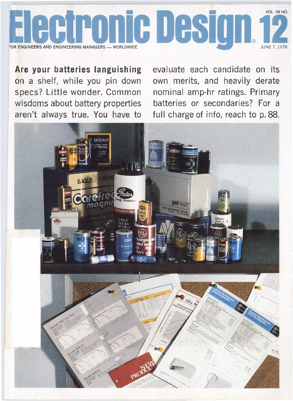
Are your batteries languishing
on a shelf, while you pin down specs? Little wonder. Common wisdoms about battery properties aren't always true. You have to
evaluate each candidate on its own merits, and heavily derate nominal amp-hr ratings. Primary batteries or secondaries? For a full charge of info, reach to p. 88.
We've put it all together in one space/cost saving package.
We named it MFfTM ... our multi function trimmer. This revolutionary concept combines cermet trimmers and fixed resistors into a single prepackaged circuit. A consolidation of functions has been designed into a new product line of cost-effective DIP components.
All trimmer applications require a fixed resistor to either divide a voltage or limit a current. The nine MFT trimmer models will functionally satisfy almost any trimmer application.
SAVES SPACE - MFT trimmers drastically reduce PC board space required for the peripheral components of a linear IC.
SAVES TIME - MFT trimmers reduce the time and cost of designing circuits. It also saves production time as MFT trimmers are compatible with DIP automatic insertion equipment. And, there are less components to purchase and handle.
SAVES MONEY - MFT trimmers lower total "on-board" component costs. In addition, MFT trimmer DIPS are compatible with automatic test equipment, reducing inspection costs.
INCREASES PERFORMANCE - Temperature tracking is better than discrete components ... 50 ppm/ �C. Trimmers/Resistors are manufactured simultaneously on a common substrate. MFT trimmers are more reliable as a result of pre-tested circuitry and reduction of connections.
The sealed multi function trimmers are available in nine configurations of the multiple trimmer and network combinations. Call or write today for your MFT trimmer catalog.
TRIMPOT PRODUCTS DIVISION, BOURNS, INC., 1200 Columbia Avenue, Riverside, CA 92507. Phone: 714 781-5204. TWX: 910 332-1252.
The only other professional quality sweepers in our price range that we know about make a loud noise and are constantly needing their bags emptied.
So if you're more interested in clean sweeps than clean floors, we recommend our Model 1061. It sweeps from lMHz to 400MHz at
line frequency, with excellent
you a sweeper with a three-digit �
signal quality. Output flatness is
price tag, watch out. You may be
� 0.25dB, sweep linearity 2%.
The calibrated output is + 10 to
getting sucked in. Wavetek Indiana, Inc. 66 N.
-60 dBm and you have a choice of First Ave., P.O. Box 190, Beech
either 50-ohm or 75-ohm output
Grove, Indiana 46107. Telephone
impedance.
(317) 783-3221, TWX 810-341-3226.
v /AV, E T E All for $675.
'
But if anyone else tries to sell
Av~
~
The only Double �Balanced llixers with a 2� YBIB IUIB.&1111.
featuring Hi-Rel tested diodes�
Introduced in 1971 at $7 .95 ...
still only
S7.Q.~, $9.95 (1-49)
�including diodes!
Yes, a two-year guarantee for hermetically sealed DBM 's is now a reality ... made possible by an accelerated-life diode screening program adopted at Mini-Circuits.
Each Schottky diode used in Mini-Circuits' SRA-1 mixers is now preconditioned by the HTRB (High Temperature Reverse Bias) technique, previously reserved almost exclusively for semiconductors assigned to space applications. With HTRB testing , each diode is operated for 168 hours
at 1so �c with one volt reverse bias applied.
To screen out " infant mortality ", the diodes are deliberately stressed to accelerate aging and to force time-related failure modes to take their toll. In conventional testing or " baking ", the diode does not experience anywhere near the stress encountered with the HTRB program. Hence, the ability at Mini-Circuits ' to locate the potentially-unreliable diodes before they are assembled into SRA-1 units And, with double-balanced mixers, the overall re� liability hinges almost entirely on the diodes used.
Yes, the HTRB procedure costs us more and screens out more devices. But our goal is to improve reliability to a level unmatched for off-theshelf DBM 's at no increase in cost to our customers. You - our customers by your overwhelming confidence in our product line have made us the number one suppl ie r of DBM 's in the world .
To earn your continuing support, we are now employing HTRB Hi-Rel testing for every diode used in the SRA-1 , at no increase in cost to you . So , for the same low price of $7.95, you can purchase our SRA-1 , with a two-year guarantee, including diodes.
To ensure highest system reliability demand highest quality diodes on your source-control drawings and purchase orders. Specify SRA-1 mixers, with HTRB tested diodes from Min i- Circuits: .. where low price now goes hand-in-hand with unmatched qua11ty.
MODEL SRA-1- - -- - -- - - - -
Freq . range IMH1l LO . 0 5-500. RF 0 5 500. IF de 500
Conversion loss ldBl One oc tav e from band edge To tal range
Typ . Max . 5 5 7.0 65 85
tsol at1on ldBI Lower ba nd edge l o one decade highe r Mid 1ange
Up�e1 ba nd edge to one oc tave lowe1
LO �RF LO -RF LO�RF LO -IF LO �RF LO �IF
Typ. Min. 50 45
45 35
45 30
40 25
35 25 30 20
Min. Electronic attenuation 120 mAI 3 dB
+ Signal, 1 dB compression level I dBm
Impedance all port s 50 ohm s
2625 East 14th Street Brooklyn, New York 11235 (212) 769-0200 Domestic and International Telex 125460 International Telex 620156
lnlernallon�I RepreHnfatins: 0 AFRICA : Al1t ra (PTY) lid P 0 Box 9813 Johannesburg 2000 S Africa 0 AUSTRALIA: General Elec 1romc Services 99 A lexander S1ree 1 New South Wales A ustraha 2065 0 ENGLAND : Da l e Elec lro n1 cs Dale House. Wharf Road Fr 1mley Green Camberley Surrey 0 EASTERN CANADA : B D H ummel 2224 Mayna rd Avenue. Utica NY 13502 (31 5) 736-7 8 2 1 D FRANCE : SC I E - DI M ES 31 Rue G Porge - Sand 91120 Pala1seau France D GERMANY. AUSTRIA. SWITZERLAND. DENMARK: lnduslnal Elec1romcs G MBH 6000 Frankf urt / Main Kl uberstrasse 14 West Germa ny 0 INDIA: Gaekw ar Enterpnse Kama Mahal M L
Oana nukar Marg B o mbay 400 026 India 0 ISRAEL : Vectromcs lid 69 Gordon Slreel Tel� Avtv Israel 0 NETHERLANDS. BELGIUM, LUXEMBOURG � Co1mex Veld weg ti Hattem Holland
0 N ORWAY Da1amat1k AS Oc;tPn!\1011e1Pn 62 Oslo 6 Norwav 0 SINGAPORE & MALAYSIA Elec1ron1cs Trading Co tPTEJ Lid 87 Buk1 1 Trmah Road Singapore 9 M alay Peninsula O SWEDEN l n1eqe1ad E1ec11onik AB Box 43 5�18251 D1ursho!m Sweden
U.S D1str1butors 0 NORTHERN CALIFORNIA� PENN�STOCK Co Fool hrll Qlhce Cen1e1 105 Fremont Avenue Los Altos CA 94022 (4151 948~6533 0 SOUTHERN CALIFORNIA . ARIZONA C1own tl(>Clronics 11440 Colhns ~trPet No Hollywood CA 91601 t2131 877-3550 NEW YOAK ; MICROWAVE OISTRIBUiORS COMP"NV
61 Malt Dri11e Commack N v 11ns 516 543.4771
CIRCLE NUMBER 3
R 16/Rev/E
NEWS
49 News Scope 54 Z 800016-bit�Cfamilywill challenge minis. 60 ln-circuittests find more faults on PC boards. 64 Faster, denser static RAMs push into new designs. 76 Lower-costfixed discs will fill in the gaps. 81 Washington Report
TECHNOLOGY
88 Focus on batteries: Battery specs are expressed in a special jargon : Understand the jargon , derate heavily and you 'll avoid trouble .
104 Pick the right de/de converter for your switch-mode power supply. Different circuit types determine the characteristics of the magnetic components.
112 Protect your rechargeable battery. Put hysteresis into the discharge-sensing circuit so that the load stays removed-even as battery-voltage rebounds.
116 Develop cooperative �P subroutines that exchange information without hogging memory. The clue: a routine based on register-controlled stacking.
122 Reduce your �C system's overhead. With a system-monitor analysis of the system 's operations, you can spot possible bottlenecks in program execution.
128 Puttestability into PC boards during the design stage. You'll make it easier to diagnose and isolate faults automatically, and you'll cut the cost of repair .
134 Test your charge-pump phase.detectors. Pinpoint the nonlinearities so you can operate your detectors in the good part of their characteristics.
140 George Bugliarello of Polytechnic Institute of New York speaks on expanding your research capabilities.
144 Ideas for Design: Sample-and-holds and a summing amplifier form an analog memory unit. Quad comparator provides two functions-level shifting and time delays. Turn a car's side marker lamps into 'turn' signals with a CMOS gate.
152 International Technology
PRODUCTS
155 ICs &Semiconductors: PROM family is fastest and densest-and plugs right into expandabil ity.
162 Micro/Mini Computing: Alphanumeric and graphic boards include microprocessor software.
188 Data Processing: Computers family get high speed from hardware arithmetic
unit.
190 Data Processing: Bell-compatible high-speed modem comes as single board .
178 Packaging & Materials
208 Instrumentation
195 Modules & Subassemblies
210 Power Sources
202 Components
DEPARTMENTS
85 Editorial: Sharing vital information
7 Across the Desk 212 Evaluation Samples 212 Vendo~ Report
221 Employment Opportunities 230 Advertisers ' Index 230 Information Retrieval Card
213 New Literature
Cover: Photo by Art Director, Bill Kelly. Batteries courtesy of Eagle Picher, Gates,
GE, Globe , Gould, Mallory, Marathon, Ray-0-Vac, and Union Carbide. And spec sheets
are from El power, Gates, Honeywell, Panasonic, Power Conversion and Ray-0-Vac.
ELECTRONIC DESIGN is published biweekly except 3 issues in July by Hayden Publishing Company. Inc.. 50 Essex St. . Roche lle Park. NJ 07662. James S. Mulholland Jr.. President. Printed at Brown Printing Co.. Waseca . MN Controlled circulat ion postage paid at Waseca . MN and New York, NY. postage pending Rochelle Park, NJ. Copyrightc 1978. Hayden Publishing Company. Inc. All rights reserved . POSTMASTER: Please send form 3579 to ELECTRONIC DESIGN , P.O. Box 13803, Ph iladelphia. PA
19101.
ELECTRONIC DESIGN 12, June 7, 1978
3
Watch this space for a whole new family of microprocessor components designed by Advanced Micro Devices.
They're built from your side of the board. They're microprocessor-based solutions from a system viewpoint.
For example:
DMAWITH
EVERYTHING ON IT.
Advanced Micro Devices' new Am9517. It's a multimode DMA controller that lets you transfer information directly
MOS
MICROPROCESSING:
WE.REON
YOUR SIDE.
4
ELECTRONIC DESIGN 12, June 7, 1978
from your peripheral controller to your system memory at blinding speeds of up to 2 million words per second. And that's just the beginning.
The An19517 is a 40-pin, 5V only, N-channel, silicon-gate device that implements four fully independent DMA channels and includes provision for unlimited expansion.
Software control provides automatic reinitialization of all channels upon completion or external tem1ination of a DMA transfer.
It's got everything: Memory-to-n1emory trans�er, address increment or decre1nent and software DMA request capability offer powerful data manipulation options. Software control of the polarity of DMA request and acknowledge signals-plus
a simple interface-provide easy inter�acing with a great variety of microprocessor systems. And, as always, MIL-STD-883 for free.
(For those designs that don't need everything, we supply the Arn8257, a plug-in replacement for the Intel 8257.)
If you're looking for a DMA controller that looks at microprocessing the way you do, call us.
Advanced Micro Devices
~
Multiple technologies. One product: excellence. 901 Thompson Place, Sunnyvale, California 94086
Telephone (408) 732-2400
CIRCLE NUMBER 4
E1.1�.CTR 0 1c D ES IGN 12, June 7, 1978
s
-�� ,, _.,.,,...,
�""
One- and three-phase rack-mounted power supplies from 500 to 10,000 watts. Call TOLL FREE 800-631-4298 for complete information and prices, or write for our catalog.
6Y~M ELECTRONIC MEASUREMENTS INC. 405 Essex Road, Neptune, N.J. 07753 Phone: (New Jersey) 201-922-9300. TOLL FREE 800-631-4298 Specialists in Power Conversion Equipment CIRCLE NUMBER S 6
Publisher
William Maass
Associate Publisher
George Rostky
Editor
Laurence Altman
Managing Editors Ralph Dobriner Michael Elphick
Senior Editors Stanley Runyon Stephen E. Scrupski
Associate Editors Sid Adlerstein Nicholas Bodley Dave Bursky Morris Grossman Gene Heftman Andy Santoni Max Schindler
Contributing Editors: Jules H. Gilder, Alfred D. Gronner, Sidney Moskowitz, Nathan Sussman
Editorial Offices
Headquarters 50 Essex St. Rochelle Park, NJ 07662 (201) 843-0550 TWX: 710-990-5071 (HAYDENPUB ROPK) Cable: Haydenpubs Rochellepark
East Jim McDermott, Eastern Editor P.O. Box 272 Easthampton, MA 01027 (413) 527-3632
West 8939 S. Sepulveda Blvd., Suite 414 Los Angeles, CA 90045 (213) 641-6544 TWX-1-910-328-7240
Dave Barnes, Western Editor 465 S. Mathilda, Suite 302 Sunnyvale, CA 94086 (408) 736-6667
Editorial Production
Marjorie A. Duffy, Production Editor James Keane, Copy Editor
Art
Art Director, William Kelly Richard Luce, Anthony J. Fischetto
Business Manager
Thomas E. Vachon
Production
Manager, Dollie S. Viebig Edward J. Grimm, Paul lnCalcatera
Circulation
Director, Barbara Freundlich Senior Assistant, Gail Stone
Information Retrieval
Paula Greenleaf
Advertising Promotion
Director, WITliam Hussey Assistant, Judith Nappo
Reprints
Maxine Sassano
ELECTRONIC DESIGN 12, June 7, 1978
Aeross the desk
Magic circuit
Texas Instruments seems to have performed some magic if it can "Put BIFETs into your Linear Circuits" (Dale Pippenger and Dave May, ED No. 1, Jan. 4, 1978, p. 104). The instrumentation amplifier of Fig. 2 (p. 106) could care less whether a 741 or a TL081 is in the circuit, as far as input impedance is concerned. The 100-kQ resistors determine the input impedance in either case. Also, the 100-kQ resistors may look nice in Figs. 1 and 2 at room temperature, but look out for that bias current doubling every 8 to 10 C at elevated temperatures. Here a good bipolar amplifier may well produce less error!
Barry Baril Design Engineer Burr-Brown International Airport Industrial Park P.O. Box 11400 Tucson, AZ 85734
Dale Pippenger replies
In response to Mr. Baril of BurrBrown:
Obviously, the purpose of having 100-kP. input resistors on the circuits shown in Figs. 2 and 3 was merely to demonstrate that you can operate from very large source impedances with BIFET inputs and their low-input-bias currents.
Moreover, a typical bipolar amplifier may be very stable on input bias current compared to BIFETs, but only on a percentage value. For example, a 741 input-bias current changes only about 60% from 0 C to 70 C, while a TL071 would change 100% (or double) every 10�. But look at the actual numbers. The typical Li Is for the 741 going from 0 to 70 � is 75 nanoamps. The ..l Is for a TL071 would be less than 7 �A under the same conditions.
Mr. Baril is correct, though, in that there are some good bipolar amplifiers that will produce less error-for a price.
Lots of snow
While sitting out "The Blizzard of 78," I came across an even bigger snow job in the January 4 issue of ELECTRONIC DESIGN.
"Put BIFETs into your Linear Circuits" includes a section ("BIFETs hold down the noise," p. 106) that doesn't belong between the covers of ELECTRONICDESIGN. For starters, the authors categorize noise as "burst, broadband and root hertz." Burst and broadband noise are indeed well recognized, but "root-hertz noise" can only be a corruption of the unit volts (or more typically nanovolts) per root hertz. This unit is not a category for noise but rather the dimension of noise spectral density. Noise spectral density is, in turn, the usual form of measurement for broadband noise, one of the authors' other two categories for n01se.
In the second paragraph, burst noise is described in terms of "rail-to-rail jolts." Now perhaps this is a metaphor referring to the choo-choos of old. But, if it refers to power rails, the rails at TI must be a lot closer together than they are at other places, or TI must have record popcorn noise in its bipolar amplifiers.
In the next paragraph, the authors equate broadband and 1/f noise, which are generally categorized as two different regions in the noise spectrum. At low frequencies, 1/f noise dominates, but the spectral density falls with increasing frequency (hence, the term 1/f noise) until it approaches, asymptotically, the wide-band noise.
(continued on page 44)
P -C
Rotary Switches
"THE MIGHTY MINIATURE"
.
. liclty! Features
Optimum. s1mp d circuitry of a
the sophisticate
II the ad-
cvaoandndtea1dt9sessowni~(tf�cha�5m.sp, eliunamsldeoiduaanmrtoienttagerryfaa.nc�de�
.5" deep ro f tnoalsth):eMobuanste1n. r0~
IAtshvseaimllpapibnlelert!eiwrnm�ir~i--�
i1anovg.a1i1la2s bspleioms1pintlieoun�p\o1..24diapmoseittieorns1s.
~�~~'l.
. ' :l::. )>'. . '
P~ ."~ " ,;�
Rotary Selector Switches
Standard ro~:? ~i~\:fu\oer,
switche_s .. po 'lenoid opermicro-mk in1loactukrem, soomentary. etc� a. t.e.dJ,anecyo halsi�ctahteiorno.taPrryoosfw.iistc�ihn for your afR1most every military
the usage . rcial craft that flies
and comme s�ing Janco rotary
has been u
1
switches tor over 30 years.
Electronic Design welcomes the opinions of its readers on the issues raised in the magazine's editorial columns. Address letters to Managing Editor, Electronic Design, 50 Essex St., Rochelle Park, NJ 07662. Try to keep letters under 200 words. Letters must be signed. Names will be withheld upon request.
ELt CTRO NIC DESIG 12, June 7, 1978
.1-~!~o~~!!
3111 Winona Ave., Burbank, CA. 91504 Phone 213-845-7473 �TWX 910-498-2701
CIRCLE NUMBER 6 7
Intel delivers the 8-bit microcomputer,
Our newest 8085A selection is, quite simply, the world's fastest 8,bit
microcomputer. It's the 8085A,2, with a 5 MHz clock rate-66% faster than a
standard 3 MHz 8085A. Now you can achieve a new level of system performance
using the world's best selling and best supported microcomputer family.
There's a surprising measure of economy
that goes along with the 8085A,2's startling
performance. Its superior bus architecture ~�II enables you to use
relatively slow, low cost
standard memories.
You don't need the costly, high speed memories
that other high performance microcomputers
demand. In fact, at any clock rate , MCS,85TMCPUs
operate with 25o/o slower memories than even the
most efficient competitive microcomputers.
The 8085A,2's faster clock rate sets a perfor,
mance trend all MCS,85 components will follow.
That gives you the design option of 5 MHz or
3 MHz operation within the same family.
Of course the 8085A is fully
compatible with the 8085, and
offers the same growing selection
poef nm.pehmeorari1ei.sn,teprrfo:agcreasmamndable /
,
ilU.W
~3,...;:t;.,.)-, ~,~,. .Yy-�4i{-.J/_-J@-_ h
support circuitry.
_ ~Zr~
8
Eu-.CTRON IC D ESIGN 12, Jun e 7, 1978
worldS fastest the ne\Vest 8085A.
Join the Majority. Since its introduction, more major companies have chosen the 8085A than all other microcomputers combined. Almost overnight, the 8085A became the new industry standard.
Full software and bus compatibility with the familiar 8080 is one reason why. Designers have found they have a head start in implementing new MCS,85,based designs. And, the 8085A is your bridge to compatibility with upcoming Intel microcomputer advances.
# 1 in Support. Choosing the right microcomputer means more than
evaluating CPU performance. When you choose MCS,85, you get the highest performance CPU, plus a full family of compatible memories and peripherals,
and access to our fast growing software library. Making Intel your micro, computer supplier unlocks the door to the industry's most comprehensive development support, too. Our Intellec ~ and new Intellec�Series II, Microcomputer Development System speeds your product to market. It's the only development system with two high level languages, PL/M and FORTRAN. It's the only develop, ment system that gives you symbolic debugging, using ICE,85TM in,circuit emulation. And it's the only development system you'll need for today's leading microcomputers, and tomorrow's, too. Intel further supports our microcomputers worldwide with on,site FAE applications assistance, training classes and design seminars. The quickest way to get started is to order MCS,85 components from your nearest Intel distributor. Or, for a new 8085A,2 data sheet, contact your local Intel sales office or write: Intel Corporation, 3065 Bowers Avenue, Santa Clara, CA 95051. Telephone: (408) 987,8080.
intel"delivers.
Europe: Intel International, Rue du Moulin a Papier, 51-Boite 1, B-1160, Brussels, Belgium. Telex 24814. Japan: Intel Japan, K.K., Flower Hlll- Shinmachi East Bldg. 1-23-9, Shlnmachl, Setagaya-ku, Tokyo 154. Telex 781-28426.
Distributors: Almac/Stroum, Component Specialties, Cramer, Hamilton/Avnet, Harvey, Industrial Components, Pioneer, Sheridan, Wyle/Elmar, Wyle/Liberty, L.A. Varah or Zentronlcs.
CIRCLE NUMBER 7
E11 n KON1C. o~s1G 12, June 7, 1978
9
performance n a
flip microcomputer. With
,_
bytes of ROM, 32 1/0 lines, � gle +5 Volt power supply,
rs. With
the 3870 wpower
70 simplifies system design requirements, the
and lowers cost.
unit runs on flashlight
That's why it was chosen for use batteries making it
in Cambridge Instruments' Model ideal for outdoor use.
3038/2 Electrocardiograph. The
Computer Auto-
3870 receives 12 different electrode mation used Mostek's 3870 in a low
inputs, monitors the keyboard
cost programmer's console for their
input, and controls the chart re- Naked Mini 4 computer. The result :
corder pens and driver. ......:;
a control and dis-
Shakespeare Marine
play panel that
Electronics designed
facilitates initial
the 3870 into their chart
start-up, program
printing depth finder,
debugging, and
the Ultimate 1TM. It reads
troubleshooting.
and charts the number
Bell and Howell
and size of fish at depths
designed a micro-
from 6 inches to 400
film recorder, the
feet . With the 3870 as a
ABR System 100TM,
control center, the
with a 3870. They
Ultimate 1 offers more features than chose single-chip technology for
its competitors.
its design simplicity, low cost, and
Oehler Research developed a enhanced serviceability. The 3870
bullet speedometer called the
met those requirements while
Chronotach 33TM. Using a Mostek allowing additional features .
3870, it computes bullet velocity,
These are just some of the proven
CIRCLE NUMBER 8
Aers
Mostek's 3872, a chip microcomputer with 4K bytes of ROM and InSocket Expandability (ISE-1 )TMfor easy system upgrade.
For more information about Mostek's 3870 family , contact Mostek, 1215 West Crosby Road , Carrollton , Texas 75006; phone (214) 242-0444. In Europe : Mostek GmbH , West Germany; phone (49) (0711) 701045.
MOSTEI<�
� 1978 Mostek Corporation
Photo courtesy of Pleasant Grove Hospital . Pleasant Grove , Texas.
The power audio leaders
are sounding off again.
Fairchild didn 't get to be the largest manufacturer of power audio amplifiers in the United States by resting on its laurels. So here we go again.
The low-down on low.
Our new �A7307 is, modesty aside, simply the best low-cost amp for battery operation available today. Particularly at low voltage.
It's constructed on a single silicon chip using Fairchild's patented Planar process. And to save space, it's packaged in a plastic 8-pin mini-DIP with copper frame.
Power supply voltages range from 3.5 to 12 V. Power output from 0.22 to 1.6 W. Speaker impedance is 40 .And minimum working voltage is 3 V.
The low-down on high.
Our new �A783 is a high voltage monolithic integrated circuit in a 12-pin power package.
It's designed for use as an audio frequency Class B power amplifier and for 8 and 160 applications.
With 24 V of power supply voltage, you get 9 W of power output using an 8 O speaker.
The �A783 also has a wide supply voltage range from 4-30 V
Applications are primarily line operated TV and audio.
Apowerful perfOl'IWe
Our new TDA2002/2002A's are l 0 W audio power amps in 5-pin T0-220 power type packages.
The specs are powerful, too: Power supply voltage 16 V. Power output l 0 W
Speaker impedance 2 o.
Features include thermal shutdown, overvoltage protection (on the TDA2002 only) and short-circuit protection.
TDA2002/2002A's are perfect for auto and mobile radios and CB's.
All-purpose,
all-Ameriam amp.
Our new TBA820 is an integrated monolithic audio amplifier in a 14-pin plastic power package. It's constructed on a single silicon chip, using Fairchild's Planar process.
12
E11crno 1c DESIGN 12, June 7, 1978
Dev ice
TDA2002 TDA2002A
AUDIO POWER AMPLIFIERS
Power Supply Voltage Speaker Impedance
Power Output
16V, 20 , lOW
w 14.4 \I, 2 0 ' 8
14.4 \I, 40 , SW
Package
5-pin T0-220type Power package
�A783P3 �A783P4
24 V, 80 , 9W
TBA810DS 14.4 V, 4o , 6W TBA810DAS
TBA810S TBA810AS
�A706BPC
14.4\/,40 ,6 W 14V, 4o , 5.5 W
TBA800 TBA800A
24\/, 160 , SW
TBA641Bll 14 V, 40 , 4.SW
�A706APC 9V,4o, 2.2W
TBA641A12 9V, 4o, 2.2W
TBA820 TBA820L
�A7307TC
12V,8o , 2W 9\1, 80 , 1.2W 6\/,4o , 0.75W
w 3.5 \I, 40 ' 0.22
9V, 4o , 1.6W 9\/,80 , 1.2W 6\/,40 , 0.75W
w 3.5 \I, 4 0 ' 0.22
12-pin Batwing
12-pin Batwing
12-pin Batwing
14-pin dual in-line power pkg. w/bracket 12-pin Batwing
14-pin quad in-line power pkg. w/bracket 14-pin dual in-line power package 14-pin dual in-line power package 14-pin DIP
8-pin mini-DIP
Features/Mkt. Area
2-40 loads Thermal shutdown Overvoltage protection Short-circuit protection Auto radio, CB , Mobile Radio Thermal shutdown Operation 4-30 V Line operated TV & A udio
Thermal shutdown Overvoltoge protection Auto radio, CB, Mobile Radio
Thermal shutdown General purpose audio
Not recommended for new designs
Suitable for 24 V supply operation, e.g., TV and line operated radio
Not recommended for new designs
Not recommended for new designs
Not recommended for new designs
Low power supply operation Suitable for battery operation
Low cost low voltage-battery operation
The TBA820 is an inexpensive, all-purpose amplifier used primarily as a low frequency Class Bamp.
It operates over a wide supply voltage range of 3- 16 V And it's capable of providing up to 2 W of output power:
The low quiescent current in TBA820's make them extremely useful in battery operated portable applications.
Sayhello to smne old favorites.
Fairchild has the broadest and most complete power audio line in the U.S. for use in TY, radio, hi-fi, CB and industrial applications.
It covers the entire range from 3.0 to 30 V of power supply. And from less than 1to10 W of power output.
In short, we've got your amp. For details on our power audio products, or for your own power audio line card, just contact your Fairchild sales office, distributor or representative today. Or use the direct line at the bottom of this ad to reach our Linear Division. Fairchild Camera and Instrument Corporation, 464 Ellis Street, Mountain View, California 94042. Telephone: (415) 962-4903. TWX: 910-379-6435.
F=AIRCHIL.CJ
Call us on it.
(415) 962-4903
CIRCLE NUMBER 9
ELECTRO IC D ES IGN 12, June 7, 1978
13
GE's exclusive winning combination: rechargeable standby power in a DIP.
GE's new DataSentry � nickel-cadmium batteries are Dual Inline Packagedthey mount right on the card in standard pin sockets. There's no costly auxiliary mounting hardware or interconnectir.g wiring. And, the multi-pin design and rugged plastic case insure mechanical integrity. Keep in mind too that the compact size and DIP configuration make the DataSentry�standby power modules highly compatible with microelectronic P.C. board design.
Two of a kind, and any combination wins.
DataSentry � modules are available in two voltages: 2.4 and 3.6 volts. Multiples of these two sizes give you the versatility to custom match standby power to the design requirements of your system. For example, if you need 6.0v, simply combine one 2.4v module and one 3.6v module. A 4.Bv design means two 2.4v modules. And so on. Now you can match system requirements by simply combining inexpensive standard components.
The backing you need to cover
your bits.
With DataSentry<D modules, not only
can you "build-up" the right voltage for
your system. but you can also "back-up" a
wide range of memory requirements. For
example, these
versatile modules will typically support f000 ����� ��� �� --�--1�MONTH
a small memory
~ 0 100
drawing lo micro ~
amps for almost
~ 10
three months. or a i~f 1
larger memory
~
drawing one half er O.l
+
r
amp for more than five minutes.
.01, ............................. . . _.....................................
1 �A
lO "A 1 ~~:..D~Y~UR:~N~A lOO mA
1 A
GE's standby power lowers your ante ... again.
You already know you can create a non-volatile RAM through the addition of standby power. And you also know the cost savings are considerable. Now with Datasentry <D modules, you can save even more. The DIP configuration means you can take full advantage of standardized board manufacturing techniques as well as high volume soldering and cleaning processes. And that means less production time. And cost.
You can bet your bits it's a consistent winner.
Datasentry<D modules provide proven application reliability, backed up by GE's reputation as a world leader in rechargeable battery technology. Take a look at the hand DataSentry<D modules hold:
� no maintenance � continuous overcharge capability � the versatility of both high and low
discharge rate capability � flat discharge voltage profile � resealable safety vent
Now it's your deal. You can always deal yourself winning cards when you back your chips with Datasentry <D standby power modules. For a first hand look at your ace on the board, simply fill out the reply card below and mail to: Datasentry� General Electric Battery Department P.O. Box 922/Gainesville, FL 32601
fj GENERAL ELECTRIC
A world leader in rechargeable battery technology.
REPLY CARD
Title: - - - - - - - - - - - - - - - Compa n y: _ _ _ _ _ _ _ _ _ _ _ _ __
A ddress: - - - - - - - - - - - - - - City: _ _ __ _ _ _ _ s ta te :_ __ _ __ Pho n e Numbc r: _ _ _ _ _ __ __ _ __ Applica tion: - - - - - - - -- - - - Require m e nts: - - - - - - - - - - - - D Please h a v e a Sales Engineer contact m e imme diately.
� Tradem a rk o ! the Gen e ra l Electric Com pan y
CIRCLE NUMBER 10
If you want
more information please use this coupon.
~---------------------, I 0 AMERICA
D , � � � � I MGeicnreorealleIcntsrotrnuimcsent Corporation I I 600 West John Street I D Hicksville, New York, U.S.A. 11802
0 EUROPE
I 1 General Instrument
D I Microelectronics, Ltd. I Regency House, 1/ 4 Warwick Street,
I London , W1 R SWB I O ASIA
I General Instrument I International Corp.
I Fukide Bldg ., 8th Floor
1-3 Toranomon 4-Chome
I _J Minato-ku, Tokyo 105
GI MICROELECTRONICS 1978 PRODUCT GUIDE:
I m impressed. Please send me more information re.
I'm very impressed. Please call me re :
I'd like to be impressed, but your guide has been removed. Please send me a copy.
NAME :
TITLE: _ _ _ _ _ _ __
COMPANY :
ADDRESS : --------------------
CITY :
STATE/COUNTRY: _ _ _ _ __
ZIP :
TELEPHONE:_ _ _ _ _ _ __
L --------------------r-=I GENERAL INSTRUMENT CORPORATION l.!.I MICROELECTRONICS
CIRCLE NUMBER 11
16
E1.1,crnoN 1c D ESIGN 12, June 7, 1978
HOW TO PROFIT FROM THE FIRST BOOK
BASIC BASIC,
YOUR PERSONAL
OF KIM
Second Edition
COMPUTER:
Professional, Business, and Home Applications By T. G. Lewis . Describes how to
By Jim Butterfield , Stan Ockers, and Eric Rehnke. How to write KIM programs, with illustrations. # 5119-0, paper, 176 pp., $8.95
By James S. Coan. Fundamentals of BASIC programming. # 5106-9, paper, $8.95; # 5107-7, cloth, 288 pp ., $9.95
put the computer to work for you . # 5761-X, paper, 256 pp., $7.95
HOME COMPUTER SYSTEMS HANDBOOK
FORTRAN WITH STYLE: Programming Proverbs
By Henry F. Ledgard and Louis J.
Chmura. Programming style
HOW TO BUILD A COMPUTERCONTROLLED ROBOT
By Tod Loofbourrow. Provides an
By Sol Libes. A technical look at guide that conforms to the new
application of a microprocessor
personal computers.
definition of standard FORTRAN . and hands-on experience with
# 5678-8, paper, $8.45
# 5682-6, paper, 176 pp.,
robotics. # 5681-8, paper, $7.95
Available May, 1978
IloRDER FORM---15-DAYFREEEXAMINATION! -~Rush-:: the -;:ok(s~sted -:~5-da-;l
Catalog No.
Title
Price
j FREE examination. At the end of that
I
I time, I will send payment, plus postage,
or return the book(s) and owe nothing.
I
D Payment enclosed. Publisher pays post-1
j
age. Same return guarantee.
Name
I Title
I Company
I Prices are subject to change without
I notice. Offer good in U.S.A. and Canada I only.
I Ad. d ress- - - - - - - - - - - - - - - - - -.- - - -
C1ty _ _ _ _ _ _ _ _ _ _ _ State
Zip
I Send to: HAYDEN BOOK COMPANY, INC.
I Payment must accompany o rde rs from
P.O. Box numbers. Name of individual
ordering must be filled in.
I
L_ _ ~EssexStreet,RochellePark,~.07662 ----------------------E~~
ASYN C interface.
: I � . �~I
4K bytes PROM.
32 line Digital I/O.
ACTUAL SIZE.
2K bytes RAM.
E)
16-bit microNOVA.
Introducing the Data General microNOVA
Board Computer, MBC/1. The smallest,
most functional 16-bit single board micro-
computer you can buy. More power and
capability in less space than any other.
It's a full 16-bit processing unit. And it has
multiply/divide, stack architecture, data
channel (DMA) and 16-level priority inter-
rupt, 2K bytes static RAM, sockets for
up to 4K bytes of PROM. It also has async
interface, 32-line digital 1/0, optional con-
sole debug software and self-test diag-
nostics. All in a space of 7. 5 x 9. 5 inches.
It's all supported by our MBC/M
real-time multi-tasking monitor and moni-
tor emulator that lets you develop soft-
ware under Data General's AOS, RDOS
and DOS operating systems for execution
onMBC/l.
To go along with all of this, there's
a full array of compatible interfaces, design
interface support, compatible software
and excellent program development tools.
If you want more board in less room,
reserve a Data General MBC/1 micro-
NOVA Board Computer. For more infor-
mation, mail the coupon, call Data General
or your nearest full service industrial
distributor: Schweber or Wyle (Elmar/
.---------------, Liberty). Or call your local dealer. *Single unit price. Quantity discounts available.
Mail to: microNOVA PRODUCT INFORMATION
I DATA GENERAL CORPORATION, I WESTBORO, MA 01581
I I
I Name
Title
I
I Company
Tel. No.
I
I Address
I
I I City
State
Zip
I Data General Corporation, Westboro. MA 01581, (617) 366-8911. Data General (Canada) Ltd ,
I Ontario. Data Geoeral Europe, 61 rue de Courcelles, Paris, France, 766.51. 78. Data General
I Australia, (03) 89-0633. Data General Ltda., Sao Paulo, Brazil, 543-0138. Data General Middle
East, Athens, Greece, 952-0057. � Data General Corporation, 1978.
IL.--------------- microNOVA is a registered trademark of Data General Corporation.
_ ED67 I
4�DataGeneral
We make computers that make sense.
CIRCLE NUMBER 12
Aero.s.s the des�
(continued from page 7)
Next, we are given an expression for "broadband-noise spectral density," which is related to reciprocal frequency. I don't know where the authors dug up this expression, which they purport to relate to equivalent input noise. It looks suspiciously like the equation that describes excess noise (above Johnson or thermal noise) for a resistor under bias. In any case, it could hardly be the expression for spectral density, since it is dimensionally incorrect. Remember that spectral density should be V/J"HZ.
The last paragraph in the section, a discussion of "root-hertz noise," appears to be a garbled description of 1/f noise.
A. Paul Brokaw Director of Product Planning Analog Devices Inc. Semiconductor Div. 829 Woburn St. Wilmington, MA 01887
Dale Pippenger replies
A few comments relative to "The Blizzard of '78," the January BIFET article and Paul Brokaw's comments:
1. Although the term of "nanovolt per root hertz" is a narrow-bandwidth measurement of noise density, it is often referred to as root-hertz noise and is used as a meaningful test for noise. Even the popular Analog lownoise device AD504 specifies noise at 100 Hz and 1 kHz in nanovolts per root hertz. It's not exactly broadband noise -it's the noise density over a 1-Hz bandwidth at the frequencies tested.
2. The rail-to-rail jolt at the output of an op amp during burst noise is well known when used as transducer amplifiers operating at high gain. This burst of noise, or jolt, could swing the output from rail to rail even with 1mV input burst, if the amplifier were operating at a gain of, say, 10,000. The resulting 10-V burst on the output is what is referred to as "popcorn noise" due to its high energy level. Though 1 mV of input burst noise is a lot, it is not uncommon in older generalpurpose bipolar amplifiers.
3. The 1/f noise and broadband-
noise measurements are definitely separate techniques. While broadband noise is an average level of the total noise over some bandwidth (frequently 10 Hz to 10 kHz for op amps), 1/f noise is, as stated, spot noise-over a narrow 1-Hz bandwidth measured at frequencies of typically 10 Hz, 100 Hz, 1 kHz, 10 kHz and 100 kHz.
4. Regarding amplifier input impedances, we did not intend the values mentioned to be the result of external circuit techniques that yield high values. The 741 4-Mn input impedance mentioned is actually higher than the data-sheet specification for a typical value.
I do hope the snow storms are over for this winter.
Incredible
The TI BIFET article in your January 4 issue raises several questions of credibility:
1. The chip photos, claimed to be the same scale, are stated to show that the TI chip is "about the same size" as the 741 chip, but the National LF355 is "twice as large." Simple measurement of the photos reveals that the TL081
1 est c
voltages, mountings, enclosures and contact arrangements. Save
design time by selecting a standard P&B time delay relay. Or,
we'll make a special for you if your application
demands it. All built to P&B's high standards of quality and performance. Potter
& Brumfield Division AMF Incorporated,
200 Richland Creek Dr., Princeton, IN 47671. 812/386-1000.
POtter&Brumfield
is 1.97 times the 741 area, and the LF355 is 1.90 times the TL081 area.
It appears to me that TI has shown what we have been claiming all along: Even the most simple BIFET op amp chip is larger than a 741 and has an extra two ion-implant steps. Therefore, it must cost more to produce than a 741. If priced below a 741, the only valid reason is to buy market share.
2. Comparing the TL081 with the LF355 isn't cricket anyway. Comparison should have been made with the LF351, National's equivalent to the TL081. The LF355 (now LFT355), like the PMI OP15, is a precision op amp, against which neither the TL081 nor LF351 can compete in performance.
3. Although the virtues of BIFETs are considerably extolled, I believe that one must evaluate the advantages on a sound engineering basis:
a) Noise in a BIFET circuit is a function of a lot more than just the ionimplant process characteristics. In an LF355 circuit it comes primarily from the current noise in the second stage reflected by the gm of the first-stage FETs to the inputs. In fact, evaluating units from several sources have even shown popcorn noise. The best BIFET
amplifiers have yet to meet the noise performance of the best bipolar amplifiers .
b) Warm-up drift of IB and its change over even the 0 to 70-C range was not discussed. Since the input bias current is junction leakage current on the FETs, this will approximately double every 10 C. Therefore, warmed up at 70 C, the input current is equal to or greater than a number of bipolaramplifier families .
Daniel J. Dooley VP, Engineering Precision Monolithics Inc. 1500 Space Park Dr. Santa Clara, CA 95050.
Ooops!
Those of you who read our special report on data converters (ED No. 12, April 12, 1978, p. 38) and who know Russell Apfel, manager of LIC systems at Advanced Micro Devices, may get the idea that he changed his last name to Aptel. He hasn't. We did it for him, accidently. For that we apologize to Russell and promise to write 1000 times: "f not t, f not t, f not t . . ."
Misplaced Caption Dept.
So that's what an overloaded power transformer smells like.
Sorry. That Franz Xavier Messerschmidt's "A Rascal," a sculpture in the Osterreichische Galerie in Vienna.
NEW low-cost S87R industrial relay. UL recognized . Contacts rated to 20 amps, 277V AC, 50,000 operations at rated load. Contact forms to 2C. Ideal for vending machines, HVAC, home appliances and machine tool controls.
CIRCLE NUMBER 156
NEW T10 PC Board Relay.
Now sealed for flow soldering and immersion cleaning. Only .425" high allowing 0.6" center-tocenter spacing. Ideal for high density applications . Choice of 2, 4 and 6 Form C contacts for 0.1 to 3 amp switching
@ 28V DC.
CIRCLE NUMBER 157
W 58 thermal circuit breaker. Positive snap action switching up to 35 amps for under $1.00 in quantity. Exclusive blade design. Pressure actually increases unti I contacts open . . .with a " snap'.' Trip times at 200% of rated load-1 to 4 amp models 10 to 45 seconds, 5 to 35 amp models, 6 to 30 seconds. CIRCLE NUMBER 158
NEW EAX solid state AC relay. Thyristor controlled and isolated by pulse transformer circuit. Can be driven directly by logic circuits such as TTL, MOS and HTL. Terminals for 0.1" grid printed circuit board mounting. Rated 1.2 amps, 120V AC.
CIRCLE NUMBER 159
wllhthenewMiao-ModLVConcept
Anyway you want it. In ~ configuration you need. For any small Mil-Spec computer system with large
performance requirements, you can start with the ROLM� Model 5605 microprocessor. This high speed, single module processor can address 64K of memory and as many as
61 devices. It uses our semi-conductor or core memory modules.
Like the CPU, they're Mil-Spec components ready for severe environments.
Select from a full line of ROLM interfaces ranging from standard 1/0 buffers to NTDS and communications interfaces.
Tie the whole system together with a custom, or standard, motherboard ready for an enclosure of your design or the ROLM Mil-Spec Half ATR chassis.
While your system is in design & development, your software can be developed on one of the ROLM standard AN/UYK-19 processors. Since all ROLM modules are interchangeable and compatible, processors such as the ROLM 1602A can be used for programming, test and maintenance-without modification!
And your flexibility of selection doesn't stop with hardware. At no added cost you have your pick of extensive,
updated, upward compatible software with your program-
ming station. We call this the "micro-modular" approach to de-
signing a Mii-Spec computer system. It puts it all together
in a way that makes sense ; just the way you want it.
That's Why We're #1 in Mil-Spec Computer Systems
MI L-SPEC Computers
4900 Old Ironsides Drive, Santa Clara, CA 95050. (408) 988-2900. TWX 910-338-7350.
In Eu rope : 645 Hanau, MuehlatrHae 19, Germany, 06181 15011, TWX 418-4170. CIRCLE NUMBER 13
You can use our complete NRZI Magnetic Tape System with your PDP-II or Nova for under $5250.*
or,you can pay 20-100�10 more to other independent peripheral suppliers like Pertee wangco, Kennedy... and even to DEC and Data ceneral.
Then trvtojustifyit.
Unless your firm likes giving money away, Digi-Data is the only recommendation that makes sense.
And whether you need compatibility with PDP-11 or NOVA, Eclipse or even HP21 MX, it's not just our price advantage that gives you the edge.
� It's the product reliability that results from our ultra-simplistic design. Thousands of field installations have verified that reliability.
� It's the confidence that our 16-year record of corporate stability assures.
� It's our 30-day ARO delivery for most standard configurations.
� It's our long-term record of responsible service.
� And it's the performance, serviceability and economy realized by using common designs for the many different configurations available in our Minidek, Mididek and Maxidek tape transpo rt models.
And after all what really counts is the overall value that Digi-Data provides. Whether you need stand-alone tape drives, formatted systems or minicomputer mag tape systems, Digi-Data is First in Value. Call or write today for details.
*Single quantity price. Substantial volume discounts available.
I��I- ��..DIGl-DATA
,~ ~~~~e~fun~l!~e~up, MD 20794
-
(301 ) 498- 0200
First In Value
CIRCLE NUMBER 14
,,,,
Ill
FOr all standard 11reclsl� a1111111cat1ons
You're looking at the state-of-the-art in discrete film resistor technology. MEPCO/ELECTRA'S SPA 5000 Y-the only
resistor that gives you everything you need for all your 1%, 100 PPM applications ... in one size, one style.
Whether you're building automotive, instrumentation or communications equipment, with all the tight space requirements high power handling capabilities, and broad range of values these applications require, you 'll find what you need in SPA 5000 Y .. .
with this big plus-reduced resistor inventory. MEPCO/ELECTRA SPR 5000 Y: DUAL RATED-1 /4W & 1/2W
One resistor can be used in both 1/4 and 1/2W applications,
which means dual power handling capability in the smallest possible size.
n n BROADER RESISTANCE RANGE-10 to 22 .1M
Widest resistance range for any resistor with comparable tolerance and T.C .'s. REPLACES RN55, RN60 and RN65Perfect replacement for these MIL styles with the added plus of a broader resistance range,
dual rated ... and at a better price. CWV-{350V Max.
STANDARD TOLERANCE-1 % STANDARD T.C.- �100 PPM ( :�:50PPM available) In the market for a standard precision resistor that offers better than standard specs? Find out about SPA 5000 Y. For more information .. . "Call M/E" at (817) 325-7871 . Or write MEPCO/ELECTRA Inc., P. 0. Box 760, Mineral Wells, Texas 76067.
MEPCO/ELECTRA, INC.
A ~H AMERICAN PHii.JPS COMMHT
CIRCLE NUMBER 15
Newsseope
June 7, 1978
Computer model improves fiber-optic communications
Working from a new computer modeling program to predict performance of a fiber-optics communications system, engineers at Harris Corp. (Melbourne, FL) have developed a 7.8-kilometer link for a cable-television system in London, Ontario, Canada. The system transmits at 322 megabits per second, and has two repeaters spaced 2.6 km apart.
Rather than set up rise-time budgets and add up the rise times of each system element to see if the over-all system goals are met, the Harris group uses computer models for each of the system elements-transmitter, optical waveguide, receiver, noise filter and equalizer-and, with the computer, applies a pseudorandom word to the cascaded models. The output is an "eye" diagram which shows the resulting distortion and jitter.
In comparing the computed and measured results, a Harris spokesman says, "If you lay one on top of the other, you can't tell the difference. Most people have been too scientific," he adds, "and not approached the problem in a practical way."
The system is described in a paper at this week's International Com-
munications Conference in Toronto, Canada. Author C. Richard Patispaul notes that a number of approaches have been taken for calculating error rates in avalanche photodetector receivers, including an exact solution, Monte Carlo Simulation, Chernoff bounding, and Gaussian approximations. The Gaussian approach is the most convenient, says Patispaul, although it cannot accurately predict optimum avalanche gain and the decision threshold. Patispaul notes that such factors are rarely encountered in practical receivers . Optimum gain cannot be achieved because it generally exceeds the maximum rating of the device, while decision thresholds are unimportant since the data waveform must be symmetrically limited prior to retransmission to prevent excessive pulse-width distortion.
Thus, with the Gaussian approach, he can compute noise effects and then calculate the intersymbol interference and the jitter.
Jitter comes in two forms: random and systematic. Random jitter is estimated using an approximation based on signal slope and signal-to-noise ratio, whereas systematic jitter is taken
Fiber-optic transmitter (left) and receiver (right) developed by Harris Corp. handles 322 megabits per second . First installation will be in a cable TV system in Canada .
EL ECTRONI C D ESI GN 12, June 7, 1978
from the waveform simulations. With nonregenerative receivers, the random jitter grows as the square root of the number of receivers, while systematic jitter increases linearly with the number of receivers. All taken, the degradation due to jitter was found to be about 2 dB.
The signals are transmitted over the 7.8-km link using injection-laser diode transmitters, low-loss, graded-index optical fibers and avalanche photodiode receivers (see photo).
The response time of the diode transmitter is minimized by biasing the diode above the lasing threshold and modulating the drive current around the bias point in binary fashion, with operation always in the lasing region. Average optical power output coupled from the laser to an integral fiber pigtail is more than 1 milliwatt.
The fiber pigtail is coupled to the trunk cable with a single-fiber optical connector with a maximum insertion Joss of 2 dB, and the cable fibers have attenuations Jess than 8.5 dB/km at the operating wavelength of 850 nm. A total of eight fibers are incorporated in the cable; six are used for two-way video signals and two are reserved for spares and future expansion.
The receiver comprises the avalanche photodiode and a wideband amplifier, providing a modulation bandwidth greater than 500 megahertz.
MSI beats �Ps and custom LSI-sometimes
Off-the-shelf Schottky TTL can make a better computer CPU than can custom logic or bit-slice microprocessors, says Carlton G. Amdahl, executive vice-president of Magnuson Systems Corp. (Santa Clara, CA). That's why Amdahl chose MSI over LSI for Magnuson's M80 Series ofIBMcompatible central processors.
"Bit-slice microprocessors are too restrictive to provide the performance levels we want," says Amdahl, who claims the Magnuson processor is 1.2 to 2 times faster than the equivalent IBM 360 and 370 units. The greatest advantage is in business data processing applications using Cobol, and the smallest advantage in scientific applications using Fortran.
There are microprocessors in the $200,000-and-up computer's control console, though, and the CPU architecture is designed so that higher technology devices, when they become eco-
49
nomical, can replace TTL boards easily.
The modular approach to computer architecture allows changes and upgrades in software and hardware to follow any new developments from IBM, as well as allow compatibility with Honeywell, Burroughs, and other manufacturers' machines. Emulating IBM CPUs is becoming a favorite pastime: Two Pi Company Inc. (Sunnyvale, CA) with its V32 (ED 10, May 10, p. 36) and National Semiconductor Corp. (Santa Clara, CA) with its System/400 (ED 11, May 24, p. 37).
DMM responds to rms, average and peak ac
Digital-multimeter users no longer have to be concerned if their meters respond to ac signals with average, rms, or peak readings-or carry around three different instruments to cover all needs. The Model 3030A from Ballantine Laboratories Inc. (Boonton, NJ) has switch-selectable ac response, as well as a decibel range with an adjustable reference and high sensitivity on ac and de ranges .
In audio-equipment testing, for example, average response can check sinusoidal signals, rms response can check distorted signals, and peak response can check sound waveforms and power-supply noise. In addition, the 3030A can make a gross check for distortion in sinusoidal signals: a clean sinusoid has a peak value 1.414 times its rms value.
In the decibel mode, the 3030A has rms response from 20 Hz to 50 kHz, with a reference adjustable from over 1000 n to less than 50nat1 mW. Range is more than 60 dB.
In voltage and current modes, fullscale ranges are from 20 mV to 1200 V and from 20 �A to 2 A in both ac and de modes-unlike some DMMs, which are less sensitive on ac signals. Resistance ranges are 20 n to 2 Mn.
The 3030A responds from 20 Hz to 50 kHz in the rms mode, to 110 kHz in the average mode, and to 20 kHz in the peak mode. In rms, crest factor is 10 at 650 counts and 3 at full scale of 1999 counts.
The tradeoff is cost. At $365, the 3030A is twice the price of some average or rms-only 3V2-digit instruments. And the instrument's 90-day delivery is rather long for a DMM.
CIRCLE NO. 315
50
Sensing thermal gradients raises peak IC currents
Peak currents twice as large as any previously allowed can now be handled safely in linear power devices. A temperature-gradient sensing system built into National Semiconductor's LM-138 three-terminal 5-A voltage regulator permits the chip to pass 10A pulses as often as every 2 ms.
Even with the sensitive system, the LM-138's die size is no larger than a conventional 5-A voltage regulator whose internal-protection circuits would cause the output to collapse instantly at such a transient. Of the three protection modes usually built into voltage regulators-current limiting, safe-area protection, and thermal shutdown-the new method affects only the current-limit mechanism.
"Such a sophisticated thermal control technique will be widely used, both for protection and for optimizing performance," predicts Bob Dobkin, director of advanced circuit development at National Semiconductor (Santa Clara, CA).
The gradient-sensing system makes the LM-138 adjustable-voltage regulator very useful for driving switched loads with high start-up or surge-current demands.
But the spike could come from the power line as well as the load, Dobkin points out. No matter. The new technique uses thermal time-constants within the chip to "time" the overload and permit high transients, but safely shuts the regulator down if the overcurrent persists for more than a few milliseconds.
In high-power outputs for audio or motor-control amplifiers, shutdown can be delayed without external components. The amount of delay can be controlled by deciding how close the gradient-sensing devices will be to the chip's primary heat sources, the power transistors.
Two flexible disc drives introduced at NCC
Both single and double-density recording are possible with two new intelligent flexible disc drives shown at the National Computer Conference.
Both machines, the RFS 1200 and RFS 2400 from Ex-Cell-O's Remex Div. (Irvine, CA), contain integral formatters and Motorola 6800 microprocessor controllers.
The RFS 2400 double-density ma-
chine is one of the first floppy discs to be directly compatible with IBM's double-density format, introduced last November.
The single-density Remex unit, the RFS 1200, can record 256-kbytes while the RFS 2400 holds 512 k. The 1200 uses FM recording, while the 2400 employs a modified FM system that doubles the information capacity without doubling the number of flux reversals in the disc .
Both the 1200 and 2400 machines respond to a macrocommand, as opposed to the standard single-command structures. The macrocommand is an 8-bit word that tells the disc systems to perform the complete recording operation while the controlling central processing unit attends to other computing tasks.
Self-correcting memory can cut service costs
The error-correcting features built into a new 65 kbyte �C memory board not only eliminates most data errors, but also speeds repair by pinpointing the faulty IC among the 52 dynamic RAM chips on the board.
The board's error-correction logic corrects all single-bit errors and detects all double-bit errors in each 8-bit word .
Board-edge LEDs show which IC produced the error. And the service technician can judge the frequency and severity of the fault by manually resetting the error-status LEDs and watching for the occurrence of another fault.
The fault-locating design, the MBC-064C from Mupro of Sunnyvale, CA, may cut field service costs by reducing the costly field inventory of complete replacement boards.
Raster-matrix printer charts new speeds
At 600 lines per minute, the P600 matrix printer is invading the speed territory held by full-font band and drum machines.
Introduced at the National Computer Conference in Anaheim, CA, the Printronix (Irvine, CA) printer uses a raster-matrix technique that is faster than the conventional dot-matrix. The P600 lays down a line of overlapping dots one row at a time rather than form characters serially and one at a time in, say, a 5 X 9 or 7 X 9 format.
The raster technique is also found in printers from Tally (Kent, WA) and Okidata (Mt. Laurel, NJ).
ELECT RONIC D ESIGN 12, June 7, 1978
Advertisement
Notes and observations from IBM that may prove of interest to the engineering community
To increase the power available to customers in Fridley, Minn., a Northern States Power Co. construction crew is converting a single-phase 13,800-volt line to three-phase service.
Northern States Builds with'Compatible Units'
Northern States Power Company is saving about $1 million a year in construction costs with computer management of standardized equipment assemblies and construction procedures, called "compatible units." The Minneapolis-based utility spends about $35 million a year to expand and maintain the distribution network that carries electric power from substations out to its residential and commercial customers.
"Power distribution is a huge , permanent construction program," says G.A. Breyer, superintendent of distribution performance. "We dispatch crews on more than 15,000 separate projects a year, to meet growing customer needs and repair storm damage. Just planning the materials needs of 700 people in 250 crews is a
massive job. Work can be held up while material is assembled or because a vital part is lacking. To avoid this, we occasionally sent excessive material out with a crew-a costly solution."
"A typical compatible unit," explains Les Drager, manager of business systems, "is a pole crossarm assembly, with its attaching hardware. The unit also includes standard labor hours and materials."
To specify a project, the designer selects the compatible units to be installed at each point along the construction site. The computer then explodes this input into a complete list of parts, which are drawn from stock and assembled for the crew.
"On 70 percent of our projects," Breyer points out, "the system can now
automatically 'classify' - that is, allocate - the costs of the work.
"Compatible units are entered directly into the System/370 Model 165. We have measured time savings for designers of26 percent.
"A major basis for allowing us our rate of return is the investment in our physical system. With more than a million poles in place, just maintaining an accurate field inventory has been expensive; our last count took six years. In the future, we expect the computer to keep a perpetual inventory.
"The system created a discipline for us, standardizing parts to cut down on inventory. And it has refocused our designers' attention away from bookkeeping and onto the integrity ofthe distribution system."
I
Marine Biologist Chick Gaddy on Caper's Island, east ofCharleston, South Carolina.
Preserving the Heritage
of the Palmetto State
In a program to preserve its irreplaceable natural resources, the state of South Carolina has collected data on more than 400 sites, ranging from the breeding grounds of the rare loggerhead sea turtle to stands of timber more than 400 years old.
"In South Carolina, we are very proud of the beauty and heritage of our state," says Dr. Wayne Beam of the Wildlife and Marine Resources Department, "and we want to preserve it for future generations. Now we can make recom-
mendations on land use permitting development compatible with conservation of natural resources.
"The value of the program is in rapid pinpointing of needed information," Beam continues. " We generate hundreds of thousands of characters of new data each month in our field survey work. There is no way to handle a state-wide assessment like this and have it do anything but sit in the files unless it is automated."
Areas surveyed contain rare or
endangered species of plants or wildlife, unique and outstanding natural features, historical sites and buildings. Complete information for each location is entered into an IBM System/370 at th e University of South Carolina. The goal is to provide the data that planners need to assess the impact offuture development.
Accumulated details on animals of special ecological significance include all their feeding and habitat requirements, their geographical distribution, the environmental limits they tolerate and their breeding and nursery areas.
The program is called Heritage Trust .md was developed in collaboration with The Nature Conservancy, a privately fonded organization based in Arlington , Virginia, which is working with other states on similar programs.
Beam adds: " By doing keyword searches we can quickly compile a list of all locations where the gopher tortoise has been sighted, or other such extracts. And using the computer we can do analytical work-correlating such factors as size and fecundity, to help improve commercial fish harvests.
"We recognize that we are a growing and developing state and must make the most effective use of our land from an economic as well as an ecological standpoint . The computer will give us the capability to compare sites, assess their relative importance and decide which areas contain unique values that should be prese1ved."
What is Computing Worth?
Computer services available today offer a range of interaction and responsiveness . Which is the right choice for an engineering or scientific group? How much should the service cost? How can it be justified and evaluated? Even though many vital contributions of the computer are intangible (who can put a dollar value on a computer simulation that reveals a weakness in a structural design?), an approach to potential cost-benefit analysis has evolved that is applicable across most industries and disciplines.
One emerging technique sets intangible benefits aside, and defines a concept of relative value, based on cost avoidance. The costs of completing each task by alternate methods are determined and compared, including different levels of service from the computer. One cost that can be quantified is man-
The abacus, perhaps the first computing instrument, has been relatively unchanged for over 5,000 years.
By contrast, a wide range ofoperating modes and services have been developed for modem computers. The concept of
relative value helps users select the service best suited to their needs.
hours lost waiting for "turnaround." Where workers can do other things while waiting for results , this cost is low. If the next step depends on completion of the previous one by the computer, the cost may be substantial. And productivity may be closely correlated to the response time of the system.
Studies of engineering productivity led one major aerospace company to create a dual scheduling system for batch work: This offers standard service or rapid turnaround (less than two hours) at a slightly higher internal charge. For engineers whose work is closely tied to the computer, the company found, the added productivity justifies the higher charges to the project. Another quantifiable cost is the time spent formulating a problem for the computer and writing a program. Today this time can be greatly shortened with
Advertisement
WeberProducts areTested BeforeThey're Built
Before building a prototype, engineers at Weber Aircraft use an IBM System/370 to test the structural design of airliner seats like these. One result is a seat that is both stronger and lighter.
"To determine the structural capabilities of a new design for an airliner seat, we could build a prototype, attach instruments, and physically apply loads in a test fixture ," says Gordon P. Cress of Weber Aircraft. "Then, if it didn't pass muster, we'd have to repeat the entire cycle of construction and test, which can
the aid of such options as interactive computing.
A third cost is the losses when a project is delayed. The scheduled time of many "downstream" events, such as tooling and the availability of manufacturing facilities , are tightly linked to the schedule of R&D. Often, delivery commitments have been made. And delays in R&D tend to be magnified later.
To make a comparison, the cost of computation is calculated as a function of a service parameter, such as turnaround time. Then the relative productivity of specific professional groups is plotted against that cost variable.
Finally, the intangible factors can be brought back into the analysis: the new approaches to problems, the further alternatives explored, the improved professional environment that attracts better people and encourages more effective research. These make relative value a very conservative approach that promises to become extremely useful in data processing resource management.
take many weeks. Now we can get better and much faster results by analyzing a model of the seat using the computer."
Cress is chief of structures and test for the Burbank, California, maker of interior equipment - such as galleys and passenger seats - for commercial aircraft. "We face stringent FAA requirements on the g forces our products must withstand," he adds. "At the same time, it is vital to save every possible ounce of weight. Without the computer, we would face the alternatives of putting excess structure - and hence weight - into the product, or of building and structurally testing an entire series of prototypes to produce a single design. "
Weber, a division of Walter Kidde & Company, uses an IBM System/370 to analyze a tentative design. For each section of a structure, a stress program using input data such as cross-sectional area, moment of inertia, and fixity, calculates the forces and moments on all three axes.
"With this program ," Cress notes , "we can arrive at the most structurally efficient design . It tells us which component is critical under each load. It gives us the data we need to select materials , decide the thickness or gauge required, and then determine the number and sizes of attachments. If one of a pair of units-say, two galleys back to back-will lean on the other under g forces, the analysis shows us this and indicates the force it will exert.
"I can instruct the computer to apply 9g forward , 4 Yig upward and Jg to one side and print out the load imparted by the acceleration on every element in the
design. The printout tells me what the stresses are at all attachment points."
Since the simulation answers questions overnight instead of taking several weeks, the design cycle is greatly shortened. When a structure must be revised, Weber engineers discover it early in product development.
Customers often ask for modifications-changing the location ofthe coffee unit or tray section in a galley, for example - which shift some weight or change the gross weight. When this happens, a computer analysis reveals immediately the impact of the change; for example, whether structural modifications are required.
"We end up with a product that meets strength and safety factor standards without adding unnecessary material," Cress adds. "As a demonstration of compliance with its standards, the FAA now accepts a structural analysis using computer-generated loads and stresses in lieu of a physical test of a prototype."
DP Engineering Dialogue is designed to provide you with useful information about data processing applications, concepts and techniques. For more information about IBM products or services, contact your local IBM branch office, or write Editor, DP Dialogue, IBM Data Processing Division, White Plains , N.Y. 10604.
-=---=--- -_ =.--.--=---'=-'-=�
Data Processing Division
News
Minis, look out: Here comes a
powerful family of 16-bit �C chips
A new family of 16-bit microcomputer chips can outperform many minicomputers. That's what Zilog Corp. (Cupertino, CA) is claiming about its Z8000 series of MOS devices.
The Z8000 family members add up to quite a range of capabilities:
� A 16-bit general-purpose CPU, which runs at a 4-MHz clock rate and can directly address up to 8 Mbytes of main memory.
� A programmable, interrupt-driven parallel 1/0 interface and countertimer circu it (CIO), which provides a TTL-compatible interface with the CPU. The CIO also can operate under DMA control and can be used in a polling operation.
� A programmable serial 1/0 (SIO) interface with two independent fullduplex channels.
� A memory manager unit (MMU) provides segment relocatability and memory protection.
� A three-channel, dual-address direct-memory-access (DMA) controller.
� Four memory chips-a 4-k X 8 quasistatic RAM with self-refresh and 200-ns access time, a 16-k X 1 dynamic RAM with 150 to 250-ns access time, a 4-k X 1 static RAM with 100-ns access, and a 256 X 8 bidirectional buffer chip.
Built with standard n-channel, silicon-gate depletion-load technology, most chips require just a single 5-V power supply and a single-phase TTLlevel clock.
The CPU, organized around sixteen 16-bit general-purpose registers, has several other 16-bit registers serving such special functions as flag control, program counter, memory-segment number and refresh control. In addition, eight of the 16 general-purpose registers may be halved into 8-bit blocks to handle single-byte operations.
Stephen E. Scrupski Senior Editor
54
zaooo functions
The segmented version of the Z8000 CPU is housed in a 48-pin package. Pin functions are as follows:
AD,5-AD0-Address/Data (inputs/ outputs, active high, three-state); multiplexed address/data lines used both for 1/0 and to address memory.
AS-Address Strobe (output, active low, three-state) indicated addresses are valid.
BUSAK-Bus Acknowledge (output, active low). A low on this line indicates the CPU has relinquished the bus.
BUSRQ-Bus Request (input, active low). This line must be driven low to request the bus from the CPU.
DS-Data Strobe (output, active low, three-state). This line times the data in and out of the CPU.
MREQ-Memory Request (output, active low, three-state, a timing signal that eases the interface to dynamic memories.
�I-Multi-micro In (input, active low) tests for the state of the multimicroprocessor request.
�0-Multi-micro Out (output, active low).
NMI-Nonmaskable Interrupt (input, active low).
NVI-Nonvectored Interrupt (input, active low).
<t>-System clock, a TTL-level clock input.
RESET-Reset (input, active low) resets the CPU.
R/ W-Read/ Write (output, lowWrite, three-state) provides early status information for a read or write cycle.
SA.-SAo-Segment Number (out-
ADl5
INTERRUPTS{
MULTI-MICRO { CONTROL
sp
ADDRESS/ DATA BUS
Z8000
ST 0
CPU
' '
'ADO
BUS RO
BuSAi<
r -- -
1 SN6
NM! VT
I
'
I
I
I I
NVI
I
:
"jLf
I
I
I SNO
"jLri
I
L_~".:1'
__sEGMENTED i
1
VERSION I
:
I
:1 : 1 SEGMENT I
:
NUMBER :
S~R~NT :
- - - - - - _J
cp 5V GND
RESET
SUBSTRATE DECOUPLE
puts, active high, three-state).
SEGT-Segmentation Trap (input, negative-edge triggered).
ST3-ST-Status (outputs, active high). These Jines specify the following statuses: memory request, stack pointer request, instruction fetch first word, instruction fetch subsequent words, internal operation or halt, VI acknowledge, NVI acknowledge, NMI acknowledge, 1/0 reference, refresh, segmentation 1/0, set bootstrap, reset bootstrap.
STOP-Stop (input, active low) single-steps instruction execution.
VI-Vector Interrupt (input, active low).
WAIT-Wait (input, active low) indicates to the CPU that the memory or I/ O device is not ready for data transfer.
WI E-Word/ Byte reference (output). N/S-Normal/System Mode (output).
ELECTRONIC DESIGN 12, June 7, 1978
00
up to 2/3 smaller.
ur ri�se:
and generally less expensive~
New Metallized Polyester Capacitors
TRW Thin Gauge X659F .022 MFD . 400V DC
TRW
ACTUAL SIZE
We call the X659F " the new dimension capacitor". It's the smallest possible size-at the smallest possible price. The advanced design of the new TRW X659F utilizes very thin gauges of metallized polyester with design highlights such as capacitance values to 20.0 MFD, dissipation factors less than 1.0% . Electrically, the new X659F is interchangeable with our X663F. Same rugged durability and long stable life.
The new X659F can help you solve many packaging problems. Oval shape allows either vertical or flat, horizontal board-hugging mounting. Where minimum space and weight are required , X659F is the answer. It's ideally suited to small portable equipment for commercial and instrument grade products.
For complete specifications and applications information, send for our new X659F Capacitor spec sheet. Call or write: TRW Capacitors, 301 West "O" St., Ogallala, Nebraska 69153. Tel: (308) 284-3611.
�1oov DC , 200V DC , 400V DC are priced lower; 50V DC higher.
T R WCAPACITORS
ANOTHER PRODUCT OF A COMPANY CALLED TRW
CIRCLE NUMBER 119
Ei.1.CT IWN IC DESIG 12 , June 7, 1978
55
Three types of interrupts-maskable, nonvectored, and vectored-can be han<lle<l by the CPU, which reduces interrupt-response times by automatically saving the program status.
Although the Z8000 CPU is similar to the Z80 processor, it is also architecturally advanced. The Z8000 provides more instructions, more data element types and addressing modes, greater power per instruction, and a larger addressing space. Moreover, programs written for the Z80 can be easily translated into Z8000 code.
The Z8000 CPU is five to 10 times faster than any 8-bit microprocessor, says Zilog, including its own Z80A, and two to five times faster than modern 16-bit minicomputers such as the PDP 11 /45.
Citing some benchmark comparisons between the Z8000 and the PDP-11 / 45, Zilog notes that, for example, the Z8000 performs its five main addressing modes-register, indirect register, direct address, indexed and immediatefaster than the 11/45 performs similar operations. The Z8000 ranges from 0.75 to 2.50 �.s, while the 11/45 ranges from 0.90 to 2.78 �.s. In addition, the Z8000 performs an add operation in about 2.25 to 3.75 �.s for various word lengths, while the 11/45 ranges from 3.68 to 6.46 �.S.
Interfacing the CPU
The CPU interfaces to such peripherals as line printers, paper-tape readers and punches, card readers and keyboards via the CIO chip, which also serves as a counter-timer circuit for real-time operations. Built to work with the �.C system's daisy-chain interrupt structure, the chip provides automatic interrupt vectoring without extra hardware.
The CIO has three independently programmable channels for counting and timing, each of which can be individually nested for priority-interrupt control. The chip also can generate system clocks and baud rates as well as count external events for realtime controls.
Handshake and pattern-recognition logic comes from two independent, 8bit bidirectional ports on the CIO; moreover, the two ports can be linked to form one 16-bit 110 port. The chip also has a special-purpose 4-bit port.
The counter-timer section consists of a 16-bit down counter, a 16-bit timeconstant register and a 16-bit currentcount register, each of which can be
56
The 8086's growing family
Already available for 16-bit designs is the 8086 family centered on the 16-bit, 5-MHz MOS device (or 8MHz with selected parts). It can address 1 Mbyte of memory with its 20 address bits. What's more, the 8086's throughput is 10 times that of the Santa Clara company's 8-bit
8080A. At the same time, Intel is provid-
ing a family of bipolar peripheral chips to work with the 8086. All the peripheral devices operate from a single 5-V supply and are housed in
20-pin packages:
� The 8284 clock generator uses a crystal or TTL signal as a frequency source and provides, along with the 8086 system clock, three extra TTL clocks for the 8288 bus controller.
� The 8282/8283 octal latch delivers three-state outputs, either noninverting (8282) or inverting (8283). So does the 8286/8287 octal transceiver, with the noninverting 8286 or inverting 8287.
� The 8288 bus controller provides decoded command signals for the 8086 and generates command signals for Intel's Multibus.
The 8086 CPU is built with Intel's HMOS scaled n-channel, depletionload silicon-gate process and consists of about 20,000 transistors. Also requiring only a single 5-V supply, it has four 16-bit registers, which can be addressed also as eight 8-bit registers; two 16-bit pointer and two 16-bit index registers; and four 16-bit segment registers to allow extended addressing.
The 8086 actually comes in two pin configurations, each in a 40-pin package-one for small systems (minimum-mode device) and for
large systems using the 8288 bus controller (maximum-mode). The
change is made by connecting one pin either to Vee or ground, which
causes seven of the other pins to change functions.
Typical instruction execution
times for the 8086 include two clock cycles, or 0.4 �.s at 5 MHz for a register increment or decrement;
three clock cycles or 0.6 �.s for register-to-register operations; and nine clock cycles plus the effectiveaddress calculation time, or a total of about 3.4 �.s, for a memory-toregister transfer.
The internal functions of the 8086 are partitioned logically into two processing units-the Bus Interface Unit (BIU) and the Execution and Control Unit (ECU).
Both the BIU and the ECU can interact, but will usually perform as separate, asynchronous operational processors. The BIU provides functions related to instruction fetching and queuing, operand fetch and store, and address relocation, as well as basic bus control. The ECU receives prefetched instructions from the BIU queue and provides nonrelocated operand addresses to the BIU. Memory operands are passed through the BIU for processing by the ECU, which returns results to the BIU for storage.
Another key feature is the 8086's interrupt-handling capability. Interrupt operations are software or hardware-initiated. Software-initiated interrupts are, of course, controlled by the specific program. Hardware interrupts, on the other hand, are either nonmaskable or maskable.
The 8086 processor provides a single nonmaskable interrupt pin, which has higher priority than the maskable interrupt-request pin. The interrupt input is edge-triggered on a low-to-high transition. In addition, the 8086 provides a single interrupt-request input, which can be masked internally by software.
programmed to serve as either counter or timer. The section also includes two 8-bit control and status registers.
To handle serial data communications, the SIO chip supports all common protocols-Bi-Sync, SDLC, and HDLC-with cyclic-redundancy character generation and checking. Data rates range up to 880 kbits/s at the 4MHz system clock rate.
In asynchronous operation, the SIO's character length can be programmed from 5 to 8 bits. Its stop bits are also programmable.
Meanwhile, unaided by the CPU, the DMA chip controls block transfers for
high-speed direct data transfer between memory and 1/0. The chip can transfer and/or byte-search at up to 1.25 Mbytes/s. What's more, with dualaddress, three-channel operation, the DMA features programmable starting addresses, block lengths and port timings .
To address up to 8 Mbytes of memory directly, the 48-pin CPU has 16 address lines plus seven memory-segment lines to work with. In addition, it can use its status lines to designate separate address spaces for code, data, and stack information for both the system and normal modes.
ELECTRONIC D ES IGN 12, June 7, 1978
TONES FOR PHONES.
Low distortion. Lower voltage.
Lowest cost.
INTERSIL'S ICM7206 CMOS TOUCH TONE� ENCODER.
This device generates pairs of sine wave tones suitable for use in a telephone handset or portable tone generator. The tone pairs are selected from a total of 8 frequencies, making this monolithic solid-state circuit suitable for use with a 4 x 3 or 4 x 4 matrix single-contact keyboard. ICM7206A and ICM7206B are standard options for use with keyboards having two contacts per key. The ICM7206A is used where the common line is connected to a positive supply and the ICM7206B where the common line is connected to a negative supply.
Distortion of output tones is only 2 to 3%, with simple filtering, decreasing in value at ascending harmonic frequencies.
LOWEST SYSTEM COST, MINIMUM PARTS COUNT.
The ICM7206 operates at supply voltages down to 3V, and dissipates less than 5.5mW at 5.5V. Packaged in a 16-pin plastic DIP, it uses a 3.57MHz standard color TV crystal and requires only nine additional components for a minimum-parts, low cost tone generator.
Since it contains an on-chip zener diode, a single ei<ternal resistor makes the circuit "latch-up" proof, and therefore resistant to high voltage transients, etc. The device is guaranteed to operate from - 40 to + 85�C. It is available in quantity from Intersil stocking distributors, priced at $3.41 in 100 piece lots. For larger-quantity prices, consult the local sales office. Send for complete data.
CUSTOM CIRCUITS ALSO AVAILABLE.
We also develop custom CMOS LSI circuits for your special telephone and telecommunications applications. Call your local sales office for information, or, return the coupon below.
INTERSIL FRANCHISED DISTRIBUTORS: Advent/ Indiana � Alliance Electronics � Arrow Electronics � CESCO Century Electronics � Component Specialties � Components Plus � Diplomat/ IPC � Diplomat/ Southland � Elmar Electronics Harvey/ Binghamton � lntermark Electronics � Kierulff Electronics � LCOMP � Liberty Electronics � R.A.E. Ind. Elect. Ltd. � RESCO � Schweber Electronics � Sheridan � Zentronics.
INTERSIL SALES OFFICES: CALIFORNIA: Sunnyvale (408) 744-0618, Carson (213) 532-3544 �COLORADO: Denver (303) 750-7004 � FLORIDA: Fort Lauderdale (305) 772-4122 ILLINOIS: Hinsdale (312) 986-5303 � MASSACHUSETTS: Lexington (617) 861-6220 � MINNESOTA: Minneapolis (612) 925-1844 � NEW JERSEY: Englewood Cliffs (201) 567-5585 OHIO: Dayton (513) 866-7328 � TEXAS: Dallas (214) 387-0539 CANADA: Brampton, Ontario (416) 457-1014.
' Registered trad ema rk of A.T. T.
nIL=m r------------------------------
u~
Analog Products - Low Power 10710 N. Tantau Avenue, Cupertino, CA 95014 Tel: (408 ) 996-5000 TWX: 910-338-0171
_ _ Please send me your product literature on your ICM7206.
Please send me a free sample* ofyour_ _ ICM7206JPE __ ICM7206AJPE __ICM7206BJPE _ _ Please send me your new Mark Twain Poster.
CompanY - - - -- - -- -- - - - - - - - - - - - - - 1
Address - -- - -- - - - - - - - -- - - - - - - - - - i
City _________ State_______ ZiP-----i 'To qualify for a free sample, attach this coupon to your company letterhead. Sample offer valid for the first 1000 industry requests received within 60 days of publication. One per person.
ZBOOO CPU
(SEGMENTED)
16 BITS i-------..---~ Z- MMU
Z-DMA
16 BITS
Z- MEMORY
(ROM+RAM) UP TOl6MB PER MMU
USER DISK AND
DATA BASE
B
ZB
16 BITS
PERIPHERAL
BITS CONTROLI..ER
16 BITS
ZB
B
PERIPHERAL
CONTROLLER BITS
SYSTEM DISK
MAGNETIC TAPE DRIVE
LINE PR INTER
B BITS
B BITS
Z-CIO
B BITS
Z-CIO
B BITS
MAGNETIC TAPE DRIVE
CARD READER
MMU ; MEMORY MANAGER
C10 : PARALLEL I /O +COUNTER-TIMER SI 0 : SERIAL 1/0 OMA : DIRECT MEMORY ACCESS
Z- SIO
CHA
CH9
MODEM
SYSTEM CONSOLE
The Z8000 family of MOS microcomputer chips can be built into a powerful 16-bit process ing unit that can cont rol co nventional computer-peripheral devices as we ll as access up to 48 Mbytes of main memory.
But since each address space can hold 8 Mbytes, a single Z8000 can actually address up to 48 Mbytes. A 40-pin version of the Z8000 is also available (it lacks the seven segment pins and segment-control pin) for directly addressing up to the conventional 64 kbytes or, with the status lines, up to 384 kbytes.
The key to the CPU's extended memory addressing is the MMU chip. Housed in a 48-pin package, it takes inputs from the CPU, the segment lines, the upper eight bits of the address, and the status information via four status bits. (The lower eight address bits go directly to the memory.) The MMU transforms its inputs into 16 bits that, when combined with the lower-order eight bits, form a 24-bit address.
With the help of another memory chip, the buffer unit, one Z8000 can interface with another or to any other Zilog Z-Bus-compatible device acting as a slave processor-for example, a peripheral controller. The 256 X 8-bit, bidirectional buffer unit has simultaneous read and write, programmable block length, and 12 programmable operating modes. The device is particularly useful for interfacing to fast peripheral devices. Or, a direct-memory
58
access chip can be used to control a fast data transfer to the buffer unit, where a second processor will draw the data out.
Dynamic-RAM refresh cycles are automatically controlled at a programmable rate by a CPU refresh row counter. Sequential RAM rows may be refreshed at intervals from 1 to 64 �s (with a 4-MHz clock). Moreover, the refresh row counter is nine bits wide to allow for future high-density memories (present 16-k dynamic RAMs have 128 rows). And, with a clock rate of 4 MHz, the counter can use slower, lower-cost, dynamic RAMs.
Interrupts and traps are handled by the CPU in similar ways. Typical interrupts are triggered asynchronously by peripherals that need attention from the CPU. Traps-synchronous events that result from executing specific instructions-occur each time an instruction is executed with the same set of data.
Changing status
When either an interrupt or a trap occurs, the old program status is pushed onto the system stack, along with an extra word that indicates why. A new program status is then fetched
from an area in the main memory pointed to by the new-program-status area pointer, a register consisting of a 7-bit segment number and an 8-bit offset value.
Not surprisingly, the Z8000 CPU has a formidable instruction set-about 110 different instructions, each of which can use the device's five main addressing modes. In addition, signedmultiply and signed-divide instructions can be implemented in hardware for both 16-bit and 32-bit data.
The instructions can operate on several types of data: bits, binary-coded decimal digits (4-bits), bytes (8-bits), words (16-bits), long words (32 bits), byte strings and word strings. Bits can be set, reset and tested. Digits are used in BCD arithmetic operations, bytes for character or small-integer values. Words are used for larger-interger values, instructions and nonsegmented addresses, and long words for longinteger values and segmented addresses.
For bits and digits, the memory address of a data type designates the byte that contains it. For data types 16 bits or longer, the address designates the left-most (high-order) byte.
A byte-data type is addressed by specifying a byte address that can range between 0 and 8,388,607 (or 65,535 for the nonsegmented version).
A bit-data type can be addressed by specifying a byte address and the bit number within the designated byte, or by specifying a word address and bit number within the designated word. The bits in a byte or word are numbered consecutively from right to left (least to most significant), 0 to 7 or 0 to 15. A word-data type can be addressed by specifying the byte address of its left-most, or high-order, byte.
In memory as well as word registers, the high-order byte is the most significant byte of the word, which allows a mixture of numeric and character data to be sorted together correctly. A double-word data element can be addressed by specifying the left-most byte of its left-most word. Quadruple words are only addressed in registers as quadruple-register groups.
As capable as the Z8000 is, it requires development support from such aids as translators for PLZ (assembly and systems languages), Basic, Cobol and Fortran . In addition, an automatic translator will help Z80 users to convert to the Z8000. Since both processors are register-oriented, the addressing modes of the Z80 are now a subset of the Z8000...
EL ECTRONIC D ESIGN 12, June 7, 1978
5 thru 120 Volt lamps, all in a
single socket. Now that's a system!
Sylvania Mix 'n Match. The only system that offers you the universal parts flexibility built around two series of T-2 slide base lamps. The first is our Pilot Lamp series spanning 5 to 120 volts. The second is our Indicator Lamp series from 4 to 48 volts.
I?ii~ SYLVANIA
CIRCLE NUMBER 17
All the lamps in each series
are physically identical. So socl~ets and lenses are fully compatible. And in o number of instances, lenses and caps
are even interchangeable between series.
As you can see, our system is
calculated to mal~e life a lot easier for everyone.
From the guy who builds the prototypes, to the guy who does the purchasing, to the guy who controls
SYSTEM production inventory. To
find out just how easy, clip the coupon and send for our handsome 17" x 22 "wall chart that graphically highlights the universal parts compatibility of
the Sylvania Mix 'n Match System.
GTE Sylvania
Miniature Lighting Products
West Main Street
Hillsboro. N.H. 0.3244
Tel: 60.3-464-55.'.>J
Why should I hove ro chonge the ~
Ss s Ill...
socker ond rhe lens whenever I change rhe lamp volrage? Send me your FREE wall charr on rhe
~
~
~ sysrem rhar's calculated to make ~
life easier for everyone.
� NAME
I COMPANY
-s=m=m--_ _ _
~,,.....,... ,~
In-circuit tests find more faults on PC boards
In-circuit testing is losing its label as a lower-cost but weaker alternative to functionally testing printed-circuit boards for final checkout. Instead, incircuit testing has become an important part of the production processafter all, it screens out the workmanship errors that account for 90% of the board failures at functional test.
In-circuit testing-which checks individual components on a PC board to determine if the proper components are mounted in the correct locations, and which checks for short and open
Andy Santoni Associ ate Editor
60
circuits on the board-is becoming so popular that the two "old timers" in the business, Faultfinders and Zehntel, are expanding their product offerings . And in just the past six months, three of the largest makers of functional test systems, Computer Automation, GenRad, and Teradyne, have introduced incircuit systems. What's more, HewlettPackard Co. (Palo Alto, CA), by far the largest test-equipment supplier, is said to be planning to introduce an incircuit tester this summer.
Test each node
An in-circuit tester generally has a "bed-of-nails" fixture with a large
number of test pins- one for each node on the board. Unlike functional testers, which usually rely on the board's edge connector for input and output, the incircuit tester does not require that power be applied to the board during the test. This allows a board to be checked quickly, and without the common "smoke test." The bed-of-nails fixture, which can cost as much as $1000, is much more expensive than the $100-or-so card-edge interface of the functional tester, but the tester itself is usually much less expensive$30,000 to $100,000 for an in-circuit tester compared to $150,000 or more for a functional unit.
The functional unit, though, offers
ELEcTRuN1c Dr.s10 12, June 7, 1978
a higher level of confidence that the board has no faults and works as designed-95% or better compared to 70% to 90% at best for in-circuit systems. In-circuit test-system vendors agree, then, that in-circuit testers are best used together with functional testers.
With just a functional tester, it may take minutes to test and isolate failures on a very complex board. But since the workmanship errors uncovered by incircuit testers can account for as many as 90% of the faults found on PC boards, prescreening with an in-circuit tester can remove many boards with these faults from the time-consuming task of fault isolation on the functional tester. So mostly good boards or boards with difficult-to-diagnose problems would have to go through fault isolation.
Indeed, the latest in-circuit tester has some functional-test capability of its own. Using signature analysis, the Troubleshooter 800 from Zehntel Inc. (Concord, CA) can inspect medium and large-scale integrated circuits, as well as discrete components. The tester generates stimuli and learns the output signatures of such devices as memories, synchronous and asynchronous receiver/transmitters, and microprocessors, and sets acceptance criteria for individual ICs. The cyclic-redundancycheck signature analysis technique is licensed from Hewlett-Packard.
Controlled by an SBC 80/20 singleboard computer, the Troubleshooter 800 has full on-line editing so that programs can be changed during the test procedure. Programs are stored on a dual floppy-disc drive. The standard tester can handle as many as 1024 points, and is priced from $50,000 to $100,000 depending on the number of test points and other options.
Medium and large-scale integrated circuits can be tested using signature analysis on Zehntel's Troubleshooter 800 in-circuit tester.
Costs cut even lower
Less expensive, but no less capable, is Computer Automation Inc.'s Mica incircuit tester. The $30,000 to $70,000 price tag results from the Irvine, CA, firm's vertical integration, explains Doug Cutsforth, who heads the Industrial Products Division's in-circuittester operation. The Mica uses Computer Automation's own peripherals, as well as its Naked Mini computer and the same operating system as the company's Capable series of functional testers.
The advantage of the in-circuit tester and the functional tester using similar
ELECTRONIC DESIGN 12, June 7' 1978
Four-line scanning increases the accuracy of GenRad's 2270 in-circuit tester. Bar-graph displays on the CRT ease potentiometer presetting and trimming.
operating systems is that all the functional tests possible with the Capable series are also possible on the Mica tester, within the frequency limits of the fixture, says Cutsforth. The Capable series includes an IEEE-488 instrument bus driver to simplify adding instruments to the basic systemand this extra is extended to the Mica system. In addition, programming is simplified-the user only enters a
parts list, and the computer handles the conversion to specific test procedures.
Software is a problem
Writing software for an in-circuit tester is easier than writing software for a functional tester, but still isn't as easy as it could be, says Al Morford, Eastern marketing coordinator for
61
Rubber-tipped pressure rods hold PC boards in place on Teradyne's L529 tester. The system screens out workmanship errors before functional testing.
Faultfinders Inc. (Latham, NY). By simply entering a parts list and nodal points, then using a known good board to check out the program and fixture , "we can generate a good program to about 85% or 90% effectiveness," says Morford, whose company is working on ways to simplify programming fur� ther, as well as on new hardware to lower testing costs. Within the next quarter, Faultfinders expects to introduce a universal test fixture with pins on 0.1-in. centers and low-cost personality cards that select the right pins for each board type to be tested.
Other changes are already taking place in in-circuit tester fixtures. In earlier designs, the spring-loaded pins that make contact with the board under test are wired to a multi-pin con� nector on the edge of the fixture via a patch panel, called a Virginia panel, that is similar to the patch panels that used to be common on analog com� puters. The patch panel made it easier to install and change pins on the fixture by eliminating the need to solder directly to the interface connector, but Virginia panels aren't very dense-a major consideration in systems with hundreds of pins.
Instead, tester makers and independent fixture suppliers such as Everett/ Charles Inc. (Pomona, CA) are wiring from the test probes to interface receptacles. The receptacles are permanen Uy wired to the test-system interface connector.
There is a unique fixture on Teradyne Inc.'s 1529 in-circuit tester.
62
The lowest-cost in-circuit tester using a bed-of-nails fixture is Computer Automation's Mica 5000 system. Its price, as low as $30,000, is less than halt that of some competitors.
�
An IEEE-488 interface and 19 programming and control card slots help expand the Faultfinders FF303 incircuit tester into a functional test system as well.
Instead of holding the board in place with a vacuum during testing, as all the other manufacturers' systems do, the Boston, MA, firm employs a special fixture that includes an array of pressure rods to hold the board down. There's no air pump-and no need for connecting to a vacuum or air supply.
But there might not be enough pressure to assure good contact, competitors say, pointing out that the fixture also does not allow access to the top of the board during testing. Access might be needed for setting calibration controls during checkout, for example. But this function is beyond the focus of in-circuit testing anyway, says Jeff Hotchkiss, product manager at Teradyne. He points out that the 1529 will most commonly be used for prescreening in conjunction with a functional board test system used for calibration.
That's also one of the reasons that Teradyne tester can use a "self-learning" technique not only for determining the values of components on the board, but also for setting tolerance limits on those values. To generate a program for a particular board type, the operator keys in a list of all components connected to each node on the board. The tester then makes resistance and impedance measurements at each node on a known-good board and stores the results. Additional known-good boards are run through the tester. Whenever a new measurement is different from previous data, the tester alters its program to adjust the median value and the tolerance band for each measurement.
At first, the test system assumes a "default" tolerance of 5% for each measurement. But the wider the variation a functionally-acceptable board can have, the wider the tolerance the tester will place on that measurement. The tolerance can reach 40% or more.
In prescreening applications, highaccuracy measurements are unnecessary. Teradyne's tester permits a wide latitude in measuring circuit parameters as long as the boards check out as working in subsequent functional checks.
Improved measurement accuracy
In some applications, though, incircuit testers have to have higher accuracies, says Michael Salter, product manager at GenRad Inc. (Concord, MA). GenRad's Test Systems Division, the leader in selling functional board testers, introduced its first in-circuit tester in February. The Model 2270, which starts at $65,000, includes a fourline scanner to switch up to four circuit-board points at a time to various measuring instruments. Compared with the three-line scanning of most other in-circuit testers, says Salter, four-line scanning permits higher accuracies .� �
EL ECTRONIC D ES IGN 12, June 7' 1978
Memory retention at 2.5 volts Vee -the 2114LV. 125mW stand-by vs. 350mW operating.Think of the power you save. And think of the complete 2114 family from Synertek. All fully static. No clocks or triggers using valuable system time. 200, 300 and 450nsec versions. The low power 2114L series- plus power down.
And Mil versions soonto-come. The broadest family of 4K static RAMs available. From Synertek, now. For specs, samples and complete information, contact Larry Hester, Synertek, 3001 Stender Way, Santa Clara, California 95051 . (408) 988-5600. TWX: 910-338-0135.
�
Synertek
CIRCLE NUMBER 18
News
Fast 4-k, and byte-wide static RAMs are pushing into new designs
New 4-k and 8-k static MOS RAMs are competing for socket territory with older static designs, especially in highspeed cache and microcomputer system designs. The battle is being joined on several fronts:
� Speed: Superfast, 4096-bit MOS RAMs are challenging bipolars in the 50-ns cache race. Meanwhile, 100 to 500-ns, 8-k and 16-k devices, organized in 1-k and 2-k X 8-bit configurations, offer micro designers convenient costsaving configurations while maintaining fast access time.
Improved 1 k and 4-k bipolar statics with 30 to 50-ns speeds nevertheless still are the choice for the fastest TTL and ECL cache and buffer systems.
� Power: Automatic, on-chip, power-down switching in new MOS statics can cut power drastically whenever a chip is unselected.
� Unclocked vs clocked RAMs: You can now get truly static storage coupled with either static or clocked (dynamic) access circuits on the periphery of a chip. Main differences are in addressing flexibility and average power consumed.
� Organization: Right now, 4-k X 1 and 1-k X 4 RAMs dominate but bytewide "by-8s" may yet take over, as they ease power drain and simplify chipselection logic. With clocked or powerdown RAMs, the wider words tend to save power, since fewer chips are on at a time.
� Pinouts: A wide choice is already on the market, and JEDEC standards are still not approved. This means designers must make prudent choices on their own.
� Capacity: The number of bits per chip is growing, but 1-k statics still dominate shipments. The consensus is 4-k statics will grow to be a volume commodity by the first half of next
Dave Barnes
Western Editor
64
�cc
a: w
~
w
>'-'
w 0 w
.."a':
w
..>
~ Ii> >-
"'
lse4K BK 16K
32K
64
MEMORY SIZE IN WORDS
These 4-k x 1 static RAMs from Intel go on low-power standby automatically. The 2141L low-power versions require only 40-mA supply current (Ice) in active operation and 5 mA on standby, which saves over 90 % of the power consumed by conventional, fully static RAMs.
year-but by then, several firms will be sampling or shipping 8-k and 16-k statics. And one firm will sample a 32-k quasistatic before the end of this year.
Speed: which nanoseconds?
Most of the new statics are in the 200 to 500-ns access-time range, which makes them suitable for MOS �Ps. Meanwhile, many manufacturers are on the brink of producing 150 and 120ns NMOS 4-k RAMs. But remember clocked parts have cycle times slower than their access times. And it's the cycle time that determines how often you can read or write in a chip. The chart on p. 66 gives specifications on some of the leading static RAMs.
On the other hand, the HMOS 2147 from Intel (Santa Clara, CA) and the VMOS 4017 from AMI (Santa Clara, CA), both with 55 ns access times, are leading an attack on bipolar RAMs,
those ultrafast units that serve bipolar bit-slice �Ps and other fast processors as cache memories, writable control stores and scratchpads. Clocking doesn't apply here (yet), so cycle time is the same as access time. But there are two specs on access time to watch out for .
Address access time (tAA) is�familiar -the number of nanoseconds you wait to get data, after address bits stabilize on the RAM inputs. But there's also chip-select access time (tAcs)-the number of ns after chip-select occurs and before you get data. Chips are known by their address access times, because TAcs is usually no problem. But when power-down and fast access time are combined in the same RAM, an important tradeoff exists.
Actually, the latter of the two events (chip select and address settling after the respective access times are added) governs how fast your RAM can read. And to figure out write speed, you have to add two access times again: addresswrite (tAw) and chip-write (tcw).
But chip-select pulses often arrive a few nanoseconds after addresses settle, because they're often decoded from the address lines themselves. So most RAMs have a tAcs shorter than tAA to allow time for the decode gates to derive the chip-select term.
The 4017 has a tAA of 55 ns and a tAcs of 30 ns, while the Fairchild bipolar 93471 RAM has a tAA of 30 ns and a tAcs of 25 ns. As long as the address decoding takes less than 25 or 5 ns, respectively, the RAMs will perform just as fast in a memory system as a glance at their tAA specs implies.
But Intel's 2147 may not. Its tAA is 55 ns, but its tAcs is 55 ns if the chip has been deselected for more than 55 ns, and 65 ns if deselected for less . This is because deselection starts the chip's powering down process, and some time is lost in powering back up.
Avoid short turnoffs, then, and the
ELECTRONIC D ESIGN 12, June 7, 1978
2147 will recycle at 55 ns-provided you can get the chip select decoded that soon. The AMI 4017 and the 93471 don't have this problem, because they don't have the valuable power-down feature. But Motorola's MCM 2147 claims to have the power-down feature without short turnoff time problems.
One other caveat on speed: The 2147 and the 4017 are specified with min/max ns values, but the Fairchild 93471 data sheet has only typicals. And the best production testing has about � 2 ns accuracy.
A hot issue
As the trends of more memory per system and more memory per chip continue, the problem of too much heat per board becomes inevitable. RAM manufacturers are reducing chip power, not only to cut heat, but to cut power-supply and cooling costs for the OEM.
Though the single +5-V supply has become the rule for virtually all static RAMs, the approaches to cutting power consumption vary.
As the chart indicates, one major way to cut average power per chip is to clock dynamic MOS peripheral circuits. Another is automatic on-chip power-down, which is controlled by the chip-enable (chip-select) pin. Indeed, one static RAM, the 8-k 8108 from EMM Semi (Phoenix, AZ) features both clocking and power-down, for impressive savings in the standby mode (see chart).
With either power-down or clocking, power buses on the PC board should have lower inductance than buses used for full-power statics. And there should be more decoupling capacitors because current transients in the 5-V lines are large and rapid.
Second-sources for the Intel 2114 static RAM abound. The SY 2114 from Synertek (Santa Clara, CA), the 7114 from lntersil (Santa Clara, CA) and the 9114 from AMD (Sunnyvale, CA) have minimum output drives of 3.2 mA, compared with Intel's 2.1 mA. AMD's 9124, available in sample quantities now , is also 2114-compatible, but adds the power-down feature. AMl's 2114H under development will draw about 800 mW to achieve a breakthrough speed of 70 ns.
While most RAMs are still spec'd for 5 V � 5%, Texas Instruments (Dallas, TX), ational Semiconductor (Santa, Clara, CA) and Motorola (Austin, TX) among others, have begun designing commercial statics to stand � 10%, as
EL ECTRONI C DESI G N 12, June 7, 1978
the military has long required. "If a manufacturer cannot meet
� 10% on a consistent basis, he doesn't have enough margin in his design as it relates to his process," argues Ron Livingston, National Semiconductor's memory marketing manager for MOS statics.
The lowest-power 4-ks come in CMOS-standby power is at the microwatt level. But CMOS RAMs still feature premium costs. However, as more CMOS equivalents of NMOS static RAMs appear, the price gap is narrowing. Acknowledging that today's CMOS:NMOS price ratios range around 3:1 or 4:1, Intersil's memory marketing manager Ron Hammer sees the ratio "heading for only about 1.6:1, but with a nine-to-18 month lag behind NMOS."
Since RAMs are volatile, battery backup is often used in systems where data must not be lost when power goes down. Most static RAM types reliably retain stored data when their +5-V power is lowered to +2.5, so batteries need not supply full operating power. Various manufacturers spec 2.0 V for data retention, and AMD's 9130/9140 are okay down to 1.5 V.
Another battery approach is pin separation. Some RAMs have a 5-V pin for the array and another to power the peripheral circuits that complete the chip. Only the array needs power when the system is inactive.
Meanwhile, unclocked RAMs are getting the business from clocked statics. Since the fully static (unclocked) RAMs have static peripheral circuits as well as static flip-flop circuits in their storage arrays (see box), they draw relatively constant current, whether or not they are reading or writing data. Being directcoupled, fully static RAMs pay relatively constant attention to their address inputs, too.
Not so with cooler-operating clocked statics, also known as edge-triggered, synchronous or edge-activated. The leading edge of the chip-enable (CE) pulse sets off the dynamic peripheral circuits in a clocked static, and triggers the various internal clocks that get the read/ write jobs done. Then the peripheral circuits revert to ultralow power drain. The static array is the only significant load until the chip is accessed again.
The state of the address inputs is
ignored by a clocked RAM, except at the CE-fall instant and for a few nanoseconds after. The advocate> of fully static RAMs argue that their
Static RAMs are easier to use
Static RAMs are usually easier to use than dynamic RAMs because they require no refresh logic. They use a complete flip-flop to store each bit, instead of a capacitor. Since capacitor charges tend to leak away, dynamics must be refreshed, usually about every 2 ms, either by data accesses to all rows, or more typically by external refresh circuitry. Refresh usually uses about 3% of the chip's time, but often can be done when the CPU doesn't need memory access.
Dynamic cells do have fewer parts than static cells, so dynamic die sizes are smaller for the same capacity, and prices are lower: But statics are making inroads-especially in small systems, where the elimination of refresh logic saves a significant amount of power, space and/or cost.
Some new statics use only four transistors per cell instead of six, by replacing the two depletion-load transistors connected to V0 o with two smaller polysilicon resistors. Proponents of the four-transistor design report better margins, lower power, and smaller cell size.
WORD LINE
VoD
Static RAM Cell
WORD LINE
"~'"~'''''
DATA
":"
Dynamic RAM Cell
65
4k and Sk static RAM types
Device type Process Organization . Power (mW) Access/ cycle No. of Original words x bits on/ standby times (ns) pins developer (ma x)
2114
HMOS
1k x 4
525/ 525 to
370/ 370
200/ 200
18
to
450/ 450
INTEL
Fully static RAMS
without powerdown
4044 / 4046 4045/ 4047
NMOS NMOS
4k x 1 1k x 4
AM9114 NMOS
1k � 4
649/649 to
370/ 370
550/ 550 to
4 0 0 140 0
525/ 525 to
370/ 370
150/ 150 to
450/ 450
18/ 20
150/ 150 to
450/ 450
18/ 20
200/200 18 to
450/ 450
Tl Tl AMO
2147
Fully static RAMS
with chip select power down L 0
w
E R
p
0
w
E R
4244 4245 2141
8108 4801
Clocked static RAMS
26104
HM OS
4k x 1
NMOS
4k x 1} 1k x 4
HM OS
4k x 1
NMOS NMOS
1k � 8 1k x 8
NMOS
4k x 1
945/ 160 to
735/ 53
- 300/ 50
385/ 11 0 to
200/ 28
270/ 60
250/ 50
320/ 242 to
165/ 127
55/ 55
18
INTEL
to
70170
150/ 150 18
Tl
to
450/ 450
120/ 120
18
to
250/ 250
INTEL
300/ 450 22 EM&MSEMI
90/ 150 to
250/ 350
MOST EK
150/ 240 18 to
350/ 510
ZILOG
4104
NM OS
4k x 1
116/ 28
200/ 310 18 MOSTEK to
300/ 460
IM6507
HM6504 CMOS static RAMS HM6514
CM OS 512 � 8
...,I CMOS
CMOS
1k � 4
33 /. 005 '"' 25� c) 35/. 005
35/. 005
4001670 24 INTERS IL ( � 25� C)
170/ 240
18
HARRIS
300/ 420
170/ 240 18 300/ 420
HARRIS
MWS5114 CMOS/
sos
1k x 4
250� W
450
18
RCA
CDP1825 CMOS/
sos
1k � 4
5.0 mW
300
18
RCA
(continued from page 65)
RAMs are easier to understand and use as well as accessible all the time, while the clocked RAMs have cycle times about twice as long as their access times. But the clocked-static proponents point to the considerable power saved and relaxed timing requirements for address validity.
"Of course, clocked approaches are borrowed from dynamic RAMs, and tend to be more complex and less reliable, and dynamic circuits take more
66
space," notes Intel's Rick Pashley, who led the design of the 50-ns 1-k 2125 and the 55-ns 4-k 2147. "Some clocked designs have to give over 60% of the chip to the peripheral circuits," he says.
But Roger Badertscher, responsible for component development at Zilog, says, "Clocked approaches are certainly reliable. We use clocked logic on everything we make. In our 6104 clocked RAM, the peripheral portion is large percentagewise because our dynamic peripheral circuits can toler-
ate a much smaller, high-impedance array. In a fully static design, the cell has to drive the sense amp in both polarities; in ours, only one."
The Zilog (Cupertino, CA) 6104 RAM and the Mostek 4104 are similar clocked static RAMs. Neither has power-down. But Mostek specifies much lower power, while Zilog offers higher speed. Both are compatible with the pinouts of the Intel 2147 and 2141, but socket compatibility, of course, requires that the chip-select line be strobed for each access.
Going straight to 16k
The future for static RAMs is at best a mixed bag. While AMI, Intersil, RCA and Synertek may introduce 16-k statics next, in the belief that the industry won't really stop off at 8 k, Intel is working on a clocked 1-k X 8 for microprocessors. National expects to have an 8-k next year, and TI is planning to introduce two full y static
RAMs late this year, a 1-k x 8 and a
2-k X 8 that will have the 2716 EPROM pinout. And Fairchild is considering both MOS and PL statics in 4-k X 4 and 2-k X 8.
Intersil's 16-k, scheduled for introduction in the first quarter of 1979, will be a 24-pin RAM with better than 200-ns access time. And EMM Semi, while sampling the 8108 1-k X 8, is working on a 16-k static.
RCA says it intends to skip the 8k static RAM derby and plunge directly into 16-k's. The company feels that the price-per-bit of its 16-k will simply be much more attractive than any 8-k's. RCA's 16-k will be CMOS/SOS, of course, and first cut samples should be available late this year, with production quantities by the middle of 1979.
A sub-100-ns MK4801 lk X 8 static from Mostek, the MK4801-scheduled for sampling in August and volume shipments in the fourth quarter of 1978 - will feature both clocking and powerdown as options. This byte-wide 300mW RAM has 24 pins, with a pinout similar to the EMM 8108 and the Intel 2716 EPROM.
So far, getting 16-k on a static chip is challenging enough. But Zilog reports that samples of a clocked 32-k quasistatic RAM will be available late this year (see ED No. 11, May 24, 1978, p. 54). Access time is estimated at 200 to 250 ns, cycle time 300 to 450 ns. The clocked 32-k will have a dynamic storage array, but with a totally hidden on-chip refresh circuit, it will look just like a static in any �P environment...
EL ECTRONIC D ESI GN 12, June 7, 1978
-h , MEASUREMENT
� coMPUTATION
product advances from Hewlett�Packard
Capture state, timing, and glitch information sim ultan eously
JUNE, 1978
Now you can approach digital system design and troubleshooting from a timing or s tate point of view with HP's 1615A Logic Analyzer. The analyze r can be used as a 24-bit state analyzer for real-time monitoring of program execution, or as an 8-bit timing anal yzer for locating problems on control lines or other asynchronous system elements. With its cross triggering and arming capability between timing and state modes, the 1615A allows yo u to debug interaction problems between asynchronous and sync hronous system elements.
Evaluation of system performan ce at the time of a glitch, ve rification of 1/0 s tability prior to reading a port, monitoring of asynchronous handshake sequences at s pecific proble m points in a program , and many other measure ments a re eas ily accomplished with this analyzer.
Keyboard entries save yo u both de-
velopment and de bugging time . In addi-
tion , powerful trigge rin g capabilities, s ix c loc k qualifiers, a nd sophistica ted delay and occurre nce ca pabiliti es ass ure tha t the necessary timing and state information is captured for a nalysis.
Glitches greater than Sns are detected and separated from data whic h a llows them to be used a part of a trigger specification. A trace s pec ification can. inc lude both pattern a nd/or glitc h req uireme nt s on any comb ination of lines-glitches can even be captured during data trans itions .
A me nu input syste m reduces th e number and compl ex ity of front pa nel control s while retaining the necessary measurement parameters.
Simultaneous state , timing , and interactive measurements , plus glitch triggering make this logic analyzer a powerful tool for both hardware and software designers . Simple keyboard entries to pin-point areas of interest in system activity also save development and debugging time of synchronous and asynchronous digital systems.
For complete details on this new logic analyzer, check C on the HP Reply Card.
INTHIS ISSUE ~~~~~~~~~~~~~~~~~~~~~~~
lntroducing Series E calculators � Signature analysis starts paying off � New hi-rel GaAs FETs
HP's computing controller line newly expanded. Now choose the right controller for your job
Whatever your interfacing needs may be, chances are HP has a computing controller that's right for you. With a full line of controll ers, interface cards, and new user guides, HP offers you an easy-to-use system that will save you time and money.
Make Your Instruments Smart at a Price you Can Afford-ffP's 97S, 9815A,9875A
The new 97S is the inexpensive solution to automating data acquisition operations for low-cost, low-speed inslmmenlation. It combines the HP-97A fully programmable, printing calculator with a powerful BCD interface.
For applications dedicated solely to data logging, HP offers an economical solution with the new 9875A Tape Car-
tridge Unit. In addition to acting as a
peripheral mass storage device for data exchange between the HP Series 9800 desktop computers, the 9875A is a stand-alone data logger. With a built-in microprocessor, it can log data on a DC100 tape cartridge without a controller.
Where enhanced small system performance, varied interfacing capability, and a moderate price are needed, HP's 9815A computing controll er can serve as a data logger or controller for a small instmmentation system. The 9815A's Auto-Start
I MEASUREMENT COMPUTATION NEWS
feature cuts operator instmction by automatically loading and executing a program when the power is switched on. The controller also features a 16-character, alphanumeric thermal printer, two optional I/O channels, and a tape cartridge for quick storage and retrieval of 12,000 12-digit numbers. HP's four optional interface cards enable the 9815A tu interface lo a variety of HP peripherals.
For Greater Speed and Power-HP's 9825A, System 45
Consider the powerful and versatile HP 9825A control ler with vectored priority inte!Tupt for control of multi-device systems. You can increase data throughput by programming software buffers between the program and your instrument. For real-time communication with high-speed instruments, the 9825A has direct memory access (up to 400k transfers per second) and a built-in 250K byte tape cartridge. A memory load/record feature allows you to suspend processing anytime, store the complete contents of memory on tape, and continue later. A live keyboard also permits you to do calculations, call subroutines, list programs, etc., while the program is running.
If you have high-performance computational needs, HP's System 45 could be the
answer. Similar to the 9825A in its data acquisition and control features, System 45 also offers 15 levels of priority interrupt and a CRT. Its dual processors allow 1/0 and computation operations to be handled simultan eously. On the CRT, you can plot your data, create drawings, histograms, pie charts, and contour plots and circuit diagrams. To make programming faster and easier, System 45 has a typewriter keyboard and enhanced BASIC language.
Five Interface Cards and User Guides To get your system up and running fast,
plug in one of HP's standard interface cards and attach the cable to your instrument. Choose from five cards: � HP-IB-implements IEEE standard 488-1975 � Bit-Parallel-general purpose interface � Bit-Serial-RS-232-C communications interface � BCDinstrument/measurement interface and � Real Time Clock
To help you put things lik e interrupt and direct memory access into perspective, HP recently published an 110 Guide, a conceptual explanation of interfacing and HP-IB Programming Hints for Selected Instruments (9825A).
Obtain full details by checking D on the HP Reply Card.
Troubleshoot data telephone lines quickly and accurately with new analyzer
ew from Hewlett-Packard comes the 3771A/B Data Line Analyzer for making troubleshooting mea urements on telephone 1in es used for carrying high speed data . Two versions are available-the 3771A is compatible with CCITT standards, the 3771B with Bell Publication 41009. Both measure two basic types of parameters affecting data lines-steady state and transient. The steady state parameters measured are: level, phase jitter, weighted noise, noise-with-tone, and frequency shift. The transients measured are: 3-level impulse noise, phase hits, gain hits, and dropouts.
Because of the nature of the transients, they are normally measured over 15minute intervals and by measuring all of them simultaneously, the 3771A/B saves considerable operator time. Also, any comparison of results is statistically valid.
Though usable as a stand alone te t instrument, the 3771A/B al o functions as part of an automatic test system. The 3771B can be used with the HP4943A/4A Transmission Impairment Measuring Set for complete data line characterization and test ing. In addition, an option, available starting next August, will allow the 3771A/B to be controlled externally via the HP-18.
Hewlett-Packard's new 3771 A performs troubleshooting measurements to CCITI standards on high speed data transmission lines. When used with the existing HP 37708 Telephone Line Analyzer, shown in background, they provide a complete , portable data line test system.
I \f�1'Sl.IREM� \; T CO.\ fPUT"TIO.\' SEWS
New OEM switching power supply for computers and peripherals
If you're an OEM manufacturer of computers and peripherals, consider this 550 watt switching regulated power supply for your products .
Designed for use in electronic data processing equipment, HP's new 63312F multiple-output, switching regulated DC power supply provides three adjustable output voltages of +4. 75 to 5.25V, -12 to -15V,and +12to +15V. An optional fourth output can be specified by the customer to drive a CRT terminal, a motor, or control circuitry.
Featuring brownout protection, the 550W modular supply allows full output power with input voltages ranging from 87 to 127V AC for a 120V input, or 174 to 250V AC for a 240V input.
The unit's three main outputs are regulated to 0.1% for full line and load variations with ripple and noise of 0.05V p-p at the main 5V output and 0.075V p-p at the � 12 to � 15V outputs. To delay loss of DC output voltage following AC input interruptions, the supply maintains the terminal voltage for minimum carryover of 20ms under full load.
Available with barrier block or edge connector interface, ihe supply has over-voltage crowbar circuits for each of the three main outputs to help protect sensitive loads. Other protective features include output current limiting and ove1temperature shutdown. Easy access to components also allows the 63312F to be readily serviced.
Forfull details about this product, chec~ F on the HP Reply Card.
Two mobile reference standards calibrate remote measurement stations
A new measurement assurance concept is emerging in metrology to supplemen t the usual hierarchy of NBS, to company primary lab, to secondary lab. Cri tical to such a Measurement Assurance Program (MAP), is a stable portable reference which can carry a reference parameter right out to a production li ne, a fl ight line, or a communication tower.
HP now offers two such packages for verifying microwave power meters and frequency counters. The 435A-K05 Dual Power Reference fea tures two totally redundant high-stability oscillators, each of which supplies 1 mW, 50 MHz reference power frori a 50 0 source to calibrate thermistor, thermocouple, a nd crystal detector power sensors. Each output is factory-set to 1 mW, �0. 7%, traceable to the NBS.
The 435A-K06 Frequency Powe r Reference verifies frequency counters and power meters with a 10 MHz, 0.5 V standard frequency source and a separate 1 mW, 50 MHz power reference (iden tical to source of 435A-K05). The frequency reference oscillator exhibits an aging rate of <5 X 10- 10/day.
Complete specifications can be obtained by checking item G on the HP Reply Card.
i
0
435A - KOS
435A - K06
Extremely fast, convenient time and frequency measurements for a broad range of applications
The new 5391A Data Acquisition System makes over 50,000 frequency and time measurements per second. Its 8K byte memory stores up to 2,000 four-digit measurements, all under convenient control of a computing controller. The 5391A also measures successive pulse widths or periods with 2 ns resolution, characterizes signals with rapidly varying frequencies up to 500 MHz, compares the varying frequency of two input signals, or totalizes a group of serially occurring pulses. Its many applications include: Electronics - VCO testing, radar rang-
ing, data communications, measuring pulse jitter and frequency stability, studying effects of high energy radiation upon electronic devices. Mechanical Engineering - studies of: rotating machinery, turbine blade flexure, timing in fuel injection systems, highspeed mechanisms. Physics Research - studies of: time of flight (includ ing velocity and acceleration), nuclear fuel burning rates, and shock waves.
Check H on the IIP Reply Card.
HP's 5391A Data Acquisition System is capable of over 50 ,000 measurements per second in frequency, period, time interval, ratio, or totalize mode.
Signature analysis starts �paying off in digital field service
Signature analysis users report increased effi� ciency troubleshooting microprocessor-based products-in the field and on the line.
Signature analysis is the new digital troubleshooting technique for microprocessor based products. You trou bleshoot quickly and confidently-right down to the component level in production or the field. Over 200 companies have designed signature analysis into their products so they can use the low-cost, portable HP 5004A Signature Analyzer for efficient field service. For example:
On-site service. A designer of Gontrols for long-range pipe systems foresaw the difficulties of a board exchange program in remote locations. They designed their product for signature analysis and are forecasting lower downtime and reduced spares.
Field office repair. A cash register manufacturer with a new microprocessorbased product avoided retraining of a large, mechanically-oriented field service
force by redesigning their product for signature analysis. Now existing dealer personnel service the product locally.
Service center savings. The board turnaround point for a minicomputer company's board-exchange program had a high rate of "no trouble found" for bad returned boards. By retrofitting some boards for signature analysis, they can troubleshoot most of those boards.
Production line troubleshooting. A maker of computerized games used the HP 5004A Signature Analyzer to cut troubleshooting time on the production line for a very cost-sensitive product.
Check out the benefits ofsignature analysis and HP's 5004A for your products and send for a copy of A Designer's Guide to Signature Analysis. Item I on the HP Reply Card.
Economical, high-accuracy automatic network analyzer for RF/microwave measurements
You can make error-corrected vector measurements of RF/microwave networks rapidly and with resu lts formatted in the form you want with the HP 8409A semiautomatic network analyzer. This system consists of programmable signal sources covering 110 MHz to 18 GHz, network analyzer with test sets, computing controller and digital plotter, plus the applications software to operate the system and perform the enor-corrected measurements. The Hewlett-Packard Interface Bus is used to connect and control the system elements.
I ME:ASURE:ME:NT COMP UTATION NE:WS
The system's ease of operation and the straightforward nature of the software make the 8409A an outstanding system for production applications requiring highaccuracy measurements.
Check] on the HP Reply Card/or more information.
The dramatic effects of error correction are shown in this plot generated by HP's semi� automatic network analyzer system. It offers major advantages in speed, accuracy and convenience, yet costs only 50% more than a manual network analyzer.
�HEWLETT-PACKARD
NEWS
New, high-rel GaAs FET available off-the-shelf
Hewlett-Packard has developed a cost-effective standard tes t program for high-reliability Gallium Arsenide FETs that enables us to provide these devices off-the-shelf. This means that compon ent and reliability engineers can now easily and more economically obtain stabilized GaAs FETs which meet rigid specifications for applications requiring high reliability performance .
Products available under this program are based on th e recently introduced
standard HFET-1101 and HFET-1102 GaAs FET trans istors .
A unique pric ing policy distributes the cost of lot acceptance testing over the devices purchased by the various customers obtaining parts from each lot.
If you would like more information on the preconditioning and screening prog rams, designated TXVBF-110112 , check Kon the HP Reply Card.
Standard hi-rel programs will now give confidence to engineers considering the use of GaAs FETs in applications with demanding performance requirements .
Lowest guaranteed noise figure in new FET
The new HFET-1102 is a packaged microwave GaAs FET with supe rior ga in characteristi cs and the lowest guaranteed noise figure at 4 GHz in the industry-1. 7 dB maximum.
This low noi se pe rforma nce and a useful range from 1 to 12 GHz, makes th e HFET-1102 excell ent for use in critical first .stage microwave receiver/amplifi er applications in land and satellite communications, radar, avionics, and ECM.
In addition, the HFET-1102 has a high minimum s mall-s ignal associated ga in of 11.0 dB at 4 GHz and should minimize distortion even at th e moderate power levels at which the device can be operated. The HFET-1102 is packaged in th e hermet ically sealed HPAC-lOOA (100 mil s sq uare).
Check L on the HP Reply Card/or more information.
.,.:.
)'
i-
This new rugged GaAs FET, with a 1 7 dB guaranteed noise figure, 1s intended for first stages of amplifier design.
I \1F.ASUR�M�.\ T C0.\1PUT.\TIO \ ' SEWS
New optoelectronic catalog now available from HP
The 1978 Optoelectronic Designer's Catalog is here. Included in thi s 228-page volume are complete, up-to-date, detailed specifications on HP's entire optoelectronic product line.
This catalog is divided into five major product sect ions: solid sta te lamps, solid state displays, optocouplers, emitters, and PIN photodiodes. Incl uded is also a new section on fiber optic technology . Each section conta ins a selection guide, product photographs, package dimension , complete specifications, and performance graphs . Order your free copy of the catalog by checking M on the HP Reply Card.
New bipolar transistor offers superior linearity
The linearity of HP's new HXTR-5102 mi crowave trans istor at 4 GHz is unmatched by any other one-half watt bipolar transistor on the market and assures the user of minimal di stortion.
The new transistor has typical powe r output figures at 1 dB gain compress ion of 29dBm at2 GHz and 27.SdBm at4 GHz. Typical associated gain is 11. 5 dB at 2 GHz and 7 dB at 4 GHz . Class A powe radded effic iency is 37% at 2 GHz and 23% at 4 GHz. Featuring s uperior powe r, ga in and e ffi cie ncy up to 5 GHz, this NPN device is a very reliable, cost-e ffective microwave tra ns istor for applications requiring powe r and lin earity.
For more information, check N on the HP Reply Card.
Internal matching at input enables broad bandwidth designs with this 34-finger ballasted transistor.
HP introduces a new line of calculators that, logically, have no equal
With HP's new line of scientific, engineering, and business calculators-th e Series E-excellence becomes avail able at a more affordable price. Like their predecessors, the Series E calculators have the "feel" and reliability, born of quality design and construction. And like their predecessors, the Series E calculators have no "eq ual ". That is, they have HP's user-heralded RP logic for fast, efficient
problem solving that has no equal, literally and figuratively. When you add to those traditional HP qualities a number of new convenience features and a lower price, it all adds up to value.
The new conveniences include larger LED displays for improved readability, commas inserted between thousands, a new level of accuracy, and a built-in diagnostic system that tell s you 1) when yo u've
performed an incorTect operation; 2) wh y it was inconect; and 3) if the calculator isn't working.
In addition, each calculator is accompanied by a complete, modular documentation system.
For a closer look, visit your nearest HP dealer, or send for detailed literature by checking A or B on the HP Reply Card.
I, r! 3 'i, 5 6 1. 8 9 G
..
" II
.
CHS x:y
II II II II
a II II D
llDllll
I[IDI_I.ii.a� ...mm
HP-31 E. Scientific. Trigonometric, exponential, and math functions . Metric conversions . Fixed and scientific display modes, 10-digit display, and 4 separate user memories.
HP-32E. Advanced Scientific with Statistics. More math and metric capabilities than HP-31E, plus 15 user memories, hyperbolics, comprehensive statistics. Engineering, scientific, and fixed display modes. Decimal degree conversions .
HP-33E. Programmable Scientific. 49 program lines of fully merged key codes . Editing, control, and full range conditional keys, plus B user memories .
HP-37E. Business Management. Features for intuitive problem solving. Simultaneous PV, PMT, and FV. Amortization schedules , statistics with trendline forecasting , plus 5 financial and 7 user memories.
HP-38E. Advanced Financial Programmability. No previous programming experience necessary. IRR and NPV for up to 1980 cash flows in 20 groups. 2,000-yearcalendar, Sfinancial and 20 user memories, plus up to 99 program lines.
E1115t-4 Choke Che~ Road �. Rocbille, MD 20850. Ph. t301l ~18-63i0.
South- P.O. Box 10505, Atlonta, GA 303 l8. Ph. I ~I) �13-1- IOOO.
Midwe8t- 5201 Tolhit�\I. Or.. RullingMcmlows, IL60008, Ph. !3 12) 255-9800.
We11t-3939 Lunken.him Bhd . Nor1h Hollp._�ood . CA 9160-1. Ph. 1213) 87i-1282.
E uro p e-Ce ntral Mailing Depot.. P.O. Bux 529. Am:.tcheen-113 i, ~t'lherlandi.. Ph. t020J '17 20 21
J a 1um- Yukogav.a-ltev.let1-Packard Lid .. Ohai.hi Bldg.. 59-1 Yo}ogi 1-Chonw Shibu)a-ku. Tok)o 151. Ph. 03-370-2281/<n.
i i HEWLETT PACKARD
news ~ CMOEMAPSUUTRAETMIEONNT product adtt�nces from Hew lett�Pack�rd
Take a chance on a power supply and win an airline trip.
Red Eye Flights to Customer Sites
A chancy power supply's bottom-line cost doesn't show up on a price list. It shows up in increased emergency service calls, total aggravation, and catastrophic downtime costs to the customer. Our Switching Regulated Power Supplies - the Dependables - can minimize such worries.
DC to DC Units Too
DC input versions, using 48, 120 or 220 VDC as standard input voltages, are available. We can also provide units that operate from both AC and DC sources allowing easy transfer to battery back-up for UPS applications. Ask for Data S heet PM-27 for our DC/ DC Converter specifications.
Time-Proven Winners: the Dependables For over 19 years, the Dependables have proved their reliability in OEM digital applications where superior line and dynamic load regulation are needed. And their low RFI/EMI and low output ripple (less than 3 mV peak-to-peak at line frequencies) make them ideal for sensitive analog applications.
Brownoutproof: These Days, a Must The Dependables can. supply their specified regulated outputs at full load over input variations from 92 to 138 or 184 to 250 VAC. And they'll keep it up for several minutes even if the input drops to 70 or 140 VAC. If AC fails completely, the supplies will hold up for at least 30 mSec., allowing orderly shutdown or shift to optional DC back-up. Catalog DP-77 gives details on our single output supplies and brownoutproof features.
Supplies to Fit Your Application A complete family of standard models provide output voltages from 2 to 48 VDC with output power up to 2000 watts. Single and four-channel multiple outputs with options such as logic inhibit, power-fail signal, remote margin chE:ck or programming, and sequencing allow tailoring the supplies to your needs. Data Sheet PM-26 gives details on the multiple units. To find out how the Dependables can keep your system on the air and your maintenance people out of it, call or write Pioneer Magnetics, Department A,today.
1745 Berkeley Street� Santa Monica, CA 90404 Telephone (213) 829-6751 � TWX910-343-6249
CIRCLE NUMBER 19
News
Lower-cost hard-disc memory systems fill gaps in price and performance
Less-expensive hard-disc memory systems are filling the price and performance gaps between larger capacity, more expensive hard discs and floppy-disc systems, in rnuch the same way that minifloppies fit between floppies and cassette-tape memories.
While the new fixed disc systems don't offer the lowest cost per bit, they do serve applications such as smallbusiness systems for the lowest cost per function, according to George Sollman, director of product management at Shugart Associates (Sunnyvale, CA). Larger discs, with up to hundreds of megabytes, offer a lower cost per bit, but the system price is too high, says Sollman. A 25-Mbyte disc, which has more storage than is usually necessary in a small-business system, is also priced too high-$2500 to $3000. And a floppy disc drive, which costs as little as $500 to $600, can store no more than 2 Mbytes. The new 10 to 30-Mbyte fixed discs are more reasonably priced at $1300 to $2900.
The new drives come not only from Shugart, but also from California Computer Products Inc. (Anaheim, CA) and International Memories Inc. (Cupertino, CA). They all use the same technology as the Winchester disc drives from IBM. A nonremovable disc and a lightweight read/write head assembly are enclosed in a sealed housing. But while the Shugart and CalComp drives use standard 14-in. discs, the IMI drive uses a novel 8-in. platter. Prices and capacities vary, too. Shugart offers 14.5 and 29-Mbyte drives for $1325 and $1800 in quantities of 250. CalComp has a 17-Mbyte drive at $1300, and IMI has 11and25-Mbyte versions at $1500 and $2900 in large quantities.
The Shugart Model SA4000 operates from the same supply voltages as the firm's floppy-disc memories, so the
Andy Santoni
Associate Editor
76
Low-cost disc drives, like the Shugart SA4000 on the left, store 10 times the data of an 8-in . floppy (shown on the right), yet cost only about three or four times as much.
same power supply can operate with both in a system. The drive itself has no power supply, which helps cut the weight. So do a ribbed-aluminum baseplate, instead of a solid-cast one, a smaller motor than is common in disc drives, and a band actuator instead of a standard voice-coil actuator. As a result, the Shugart drive weighs all of 35 lb-80% less than some disc drives, says Sollman.
Using floppy techniques
In addition, the Shugart drive borrows some low-cost technology from the firm's floppy-disc drives. Instead of a closed-loop servo system thatSollman claims-costs the OEM $200 to $300 and decreases system reliability, the SA4000 uses a stepper motor to position the read/write heads. The tradeoff is seek time, which is 87 ms
average, 220 ms maximum. "We think that's a poor tradeoff,"
says David L. Britton, president of International Memories. The IMI drive has a seek time of 50 ms average, 105 ms maximum and a higher track density-300 per inch to 172 for the Shugart. And the technology already exists, says Britton, to develop higher-density versions of the IMI drive; 40 and 75-Mbyte versions are already in the works.
Britton prefers to lower drive costs by using smaller components-new designs, not just scaled-down versions of existing parts-and cost and weight savers like a fiberglass-reinforced polyester baseplate.
On the other hand, CalComp's 14-in. drive, like Shugart's, uses a band positioner and stepper motor. But unlike the Shugart, the CalComp keeps its seek time to 130 ms, maximum, by employing a 6800-type microprocessor.
ELECTRONIC DESIGN 12, June 7, 1978
Electronic accuracy through mechanical precision.
The microprocessor allows the stepper motor to slew at high speed with controlled acceleration, explains Don Friedman, product marketing manager at CalComp. As the head moves across the disc, it does not have to determine at each track whether or not to continue. Instead, it accelerates and decelerates directly from one track to the next track it needs to access.
The Marksman also includes a brake to halt the disc within a couple of seconds when the speed, about 3000 rpm in operation, drops below 600 rpm, as when the drive is turned off. At that point, the heads come in contact with the disc; at operating speed they ride on a cushion of air.
But braking doesn't really matter, says Shugart's Sollman. Unlike drives
The smallest hard-disc drive, from International Memories Inc., uses an 8-in. platter. It is otherwise similar to standard drives like IBM's Winchester, which use the 14-in. platter also shown here.
variable capacitors
.... made by Johanson. Quality without compromise is our target in the design and manufacture of capacitors in sizes, mounting configurations and capacitance values to meet every application. Perhaps that's why-for more than three decades-superior variable capacitors have been synonymous with the name Johanson, where standards of excellence always come first.
The heart of this trimmer consists of a one piece integral contact drive mechanism press fitted to concentric rotor tubes (U.S. Patent No. 3 ,469,160).
I ~ L..,
The
standard
of excellence!
MANUFACTURING CORPORATION Rockaway Valley Road Boonton, N.J. 07005 (201) 334-2676, TWX 710-987-8367
CIRCLE NUMBER 21
78
Access time is kept low in CalComp's Marksman drive with a 6800 �P that slews a band-positioner stepper motor at high speed with controlled acceleration .
with removable media, fixed-media drives are rarely stopped or started more than once or twice a day. Moreover, with loading of only 10 to 15 grams and improved lubrication on the disc and heads, the head can land on the disc without scoring it, he says, claiming that after 30,000 start/stop cycles "we see no degradation."
More 8-in. drives?
Shugart is also looking into 8-in. disc drives, says Sollman, adding there is "significant interest" in a drive that would be the same size as a floppy and store 5 Mbytes.
All these developments may become moot depending on IBM's moves in disc
technology, since any drive that is incompatible with IBM's is unlikely to attain great popularity. While IBM won't comment on product plans, there are industry reports that a new 8-in. IBM drive, called the Piccolo, will soon be introduced. Using thin-film discs and heads, the Piccolo could pack up to 1200 tracks per inch on a disc. The head includes diode selection and amplification circuitry as well as a small gap.
IBM or no IBM, Lee Walther, a Cupertino based consultant, says, "Magnetic oxide-coated technology has been approaching its limits." He looks forward to another generation of discs, possibly thin-film designs and possibly within the next few weeks...
ELECTRONIC DESIGN 12, June 7, 1978
Introducing Augat's patented Planar stitch-wire. A high speed, low cost system that eliminates the high engineering cost of breadboarding, complete circuit card prototyping and extensive debugging. As a result, turn around ti me can be cut by onehalf to one-third.
Augat's stitchwire system works like this. After components are mounted on Planar boards, a stitchwire machine welds � � � insulated wire to stainless steel pads.
Wiring instructions can be furnished using punched tape programs or wire lists. You can also do special wiring configurations including twisted pairs or wiring on the compo-
nent side. Changes can also be made simply, either by stitch-wire machines or by
hand soldering. Adopting
stitch-wire is easy, because Augat stocks the wiring machines and a wide range of general purpose Planar boards. Including boards compatible with most mini and microcomputers. These boards feature large etched power and ground planes.
� � � The combination of large planes and low profile wiring makes them ideal for high speed logic. What's more, we can design and produce stitchwire boards to your specifications. Or we can provide the
ELH'TRON IC D ESIGN 12, Jun e 7, 1978
CIRCLE NUMBER 22
boards and equipment you need to do the job.
Augat stitch-wire offers density and flexibility advantages you can't get anywhere else. To find out how you can get started with stitch-wire, write Augat, Inc., 33 Perry Avenue, P.O. Box 779, Attleboro, Mass. 02703. Tel. (617) 222-2202.
AU6AT"
Augat interconnection products, lsotronics microcircuit packaging , and Alco subminiature switches.
79
I
I
I
L
_J
(1 o1 8 ......... clrt:lltl)
12 3456
TYPE 908C OOAL IN-LINE
Low profile, for applications with height limitation. Molded plastic package stands up against severe environmental conditions. Excellent for use with automatic insertion equipment. Compatible with other standard DIP components. Standard resistance values from 50 to 1000, capacitor is .01 �F @ 50 WVDC. Other ratings available on special order.
TYPE 201C SINGLE IN-LINE
For use where utilization of board space is important. Conformal resin coating for mechanical and environmental protection. Bosses on plastic base give positive seating on board surface and eliminate entrapment of moisture. Standard resistance values from 50to100 o, capacitor is .01 �F@ 50 WVDC. Other ratings can also be supplied.
Cut component count...simplify board layout�.�reduce equipment size���with Sprague ECL terminating resistor-capacitor networks.
(Metanet� Metal-Film Resistors, Monolythic� Ceramic Capacitors)
This series of Multi-Comp� precision r-c networks is specifically designed for ECL terminator applications (Vrr Series Terminator, -2V) where repetitive component values and circuits are required, as in signal and data processing equipment. With up to 14 resistors and capacitors per network, their use will usually result in considerable cost reductions as
compared with discrete components. Unlike some manufacturers, Sprague makes its own resistor and capacitor chips, ensuring that performance characteristics are carefully matched for mechanical and electrical compatibility. Other Sprague Multi-Comp resistor-capacitor networks include bypassed pull-up, speed-up, and active terminator networks.
Sprague puts more passive component families into D and SIP packages than any other manufacturer:
� RESISTOR-CAPACITOR NETWORllS � MULTIPLE TANTALUM CAPACITORS � 4-TERMINAL TANTALUM CAPACITORS � MULTIPLE CERAMIC CAPACITORS � 4-TERMINAL CERAMIC CAPACITORS
(ask for Bulletins 6611 , 6611 .1, 6612) (ask for Bulletin 3542) (ask for Bulletin 3542.3) (ask for Bulletins 62426, 6243) (ask for Bulletin 6242.3)
�TANTALUM-CERAMIC CAPACITORS �MULTIPLE METAL-ALM RESISTORS
"PRECISION RESISTOR NETWORllS �MULTIPLE PULSE TRANSFORMERS �TAPPED DELAY LINES
(ask for Bulletin 6642) (ask for Bulletin 7042A}
(ask for Bulletins 7041A, 7041.1 , 7042A} (ask for Bulletin 40400) (ask for Bulletin 45004)
For complete technical data on the component type(s) in which you are Interested, write for appropriate engineering bulletln(s), as llsted above, to: Technical Literature Service, Sprague Electric Company, 347 Marshall Street, North Adams, Mass. 01247.
THE BROAD-LINE PRODUCER OF ELECTRONIC PARTS
4SR 7132
SPRllGue � THE MARK OF RELIABILITY
a
General -cab_le 'Q
I - - - - - - - - - - - ' � subsidiary
CIRCLE NUMBER 23
80
ELECTRONIC D ES IG 12, June 7, 1978
Washington report
John Rhea, Washington Bureau
Industry group pushes multibillion $ solar satellites
A campaign is being mounted to persuade Congress to launch a multibilliondollar program of solar-energy-collecting satellites. The persuaders are an industry group known as the Sunsat Energy Council, headed by Dr. Peter E. Glaser, vice president of Arthur D. Little Inc. (Cambridge, MA), who first proposed the idea 10 years ago. The group has a substantial electronics representation, including such firms as Arco, GE, RCA and Westinghouse.
Sunsat is proposing 10,000-MW solar satellites, whose generating capacity is estimated at $1700 per kilowatt-comparable to the $1400 average cost of nuclear power generators. The satellites would require no fuel and only periodic maintenance, however, so the cost gap would narrow over time. The initial thrust of the campaign is to get Congress to add initial development funds to the $15.6million planned by President Carter to be spent jointly on predevelopment studies by the Department of Energy and the National Aeronautics and Space Administration over the next four years. Under a bill co-sponsored by Rep. Ronnie Flippo (D-AL) and Sen. John Melcher (D-MT), that figure would be increased to $25million in the next fiscal year.
These funds would be only a small down payment, however, since the satellites proposed by Sunsat could cost as much as $10-billion each in production quantities, according to Econ-Inc., a Princeton, NJ, economic analysis firm .
A 10,000-MW solar-power satellite, which could supply all the electricity needs of New York City, would weigh about 100,000 tons and would have to be assembled in orbit, according to one preliminary study conducted for NASA by the Boeing Co. (Seattle). And 45 of these satellites would be able to match the present total electrical generating power of the United States.
Both photovoltaic (solar-cell) and Brayton heat-engine models have been studied. The photovoltaic satellite would be 15 miles long and 3 miles wide and be covered by about 14-billion solar cells, which would transform sunlight directly into electrical energy to be beamed down to earth via a microwave link. The Brayton heat engine satellite would use a series of four parabolic-dish antennas, each about 3.5 miles in diameter and similar to conventional radar antennas. These dishes would collect the sun's energy and direct it to a solar furnace that would drive a series of turbo-generators. The electricity produced would then be beamed to earth.
On the ground, the microwave energy would be collected by rectifying antennas (known as rectennas) measuring about 5 miles by 7.5 miles and resembling a chain-link fence mounted in strips high enough off the ground to allow farming or animal grazing underneath. Backers of the concept maintain the energy levels would be low enough to allow birds to pass through the beams without harm. Nor would the energy have any effect on aircraft or their passengers.
Pilot solar-power plant nears construction
A pilot solar-power plant is due to begin operating in September, 1981, under an agreement just signed by the Department of Energy and Southern California Edison Co. (Los Angeles). And construction of this 10-MW plant is due to begin this fall 12 miles southeast of Barstow, CA, in the Mojave Desert.
EL ECTRONIC D ESIGN 12, June 7' 1978
81
DOE will fund the solar portion of the plant at an estimated $108-million while Southern California Edison and its associates, the Los Angeles Department of Water and Power and the California Energy Commission, will provide $15million for the nonsolar portions such as the turbines, and another $5-million for operation and maintenance.
Southern California Edison will operate the pilot plant for at least five years and will distribute power to the existing electric grid. The plant will obtain steam to drive its turbine generator from sunlight reflected from a field of mirrors (heliostats) onto a boiler atop a 100-meter tower.
Even in relatively cloud-free desert regions, however, earth-based solar collectors receive about a tenth of the solar energy a satellite collects above the earth's atmosphere, which filters out the sun's rays.
Navy to buy more Phalanx ship-defense systems
The Navy plans to step up procurement of the automated Phalanx close-in weapons system, which will defend ships against low-flying, anti-ship missiles penetrating area fleet defenses.
Low-rate production began in late 1977 at General Dynamics Corp.'s Pomona (CA) division. Now the Navy is requesting $95.5-million to procure 45 systems in the next fiscal year (1979) and $88.6-million to procure another 49 systems the following year.
Phalanx uses a computer-controlled Gatling gun to knock down incoming attackers. During operational evaluation tests conducted last year, targets ranging from a Navy 5-in. shell to a B-52 bomber were automatically detected, acquired and traced but not fired upon, according to Rear Adm. Justin Langille III, the Navy's assistant deputy chief of naval operations for surface warfare. Reliability exceeded the requirement by a factor of four, according to Langille, adding that maintainability was also better than required.
'Revolutionary' aircraft avionics to be tested
Air Force Avionics Laboratory engineers have begun demonstrating the Digital Avionics Information System (DAIS), which may "revolutionize aircraft avionics and cockpit displays." The initial demonstration, called mission alpha, is the first of four close-air-support demonstrations scheduled for Wright-Patterson (Ohio) Air Force base between now and 1980. The tests will feature take-off, climb, cruise, navigation, management of aircraft weapon systems, weapon delivery and precision approach and landing.
Capital Capsules: A radar originally developed for the canceled B-1 bomber is now being
considered for the B-52 and FB-111 bombers, according to William J. Perry, under secretary of defense for research and engineering. Known as the Electronically Agile Radar (EAR) and originally developed by Westinghouse, the radar is said to be less susceptible to enemy jamming and more accurate than radars of the current B-52 and FB-111...NASA has begun experimenting with a transmitting system small enough to be packed into an ordinary briefcase to determine if it can relay medical data via the agency's own ATS-6 communications satellite and the Communications Technology Satellite, which is a joint U.S.-Canadian project. The first test was conducted May 12 at BaltimoreWashington International Airport. Data on "victims" of a simulated airplane crash were sent to medical specialists in Boston, Chicago and Brooke Army Medical Center (San Antonio, TX) .
82
ELECTRONIC DESIGN 12, June 7, 1978
If you need test and measurement instrumentation that really moves, get behind the wheels of cart-mounted in-
strumentation from Tektronix .
You can load the upper tier of a Tek Model 3 Lab Cart with your Tektronix Oscilloscope, put one or two TM 500 Mainframes on the lower decks and fill them with your own configuration of TM 500 modular plug-ins:
�DMMs
�Counters � Generators � A m p l ifiers
� Power Supplies � Plug-in Scopes � Logic Analyzers � Word Recognizers � Custom Plug-ins
There are over 30 TM 500 instruments to choose from, so you can assemble a configuration that handles several special ized applications or use each individual instrument for general purposes .
Your entire instrumentation system plugs into a power distribution unit requiring a single line cord .
You can travel to immoveable machines and probe their inner workings ... in one trip, not several. Or slip your mobile lab down a narrow laboratory aisle to give your bench more elbow room .
Or, zip across the production floor for a scope calibration . Tek instruments, ScopemobilesTM and Lab Carts have an internal common ground , an important feature if you get into sensitive digital circuitry.
And , if you need table top working space along with cart portability choose the TEK Rack Cart Model 7.
Like a moveable desk, the Rack Cart leaves a flat surface on top for charts, files and record keeping. And , 28" of
depth inside allows room to rackmount Tektronix instrumentation to the front or rear of the cart. A special option lets you rackmount a TM 500 six wide mainframe at an upward angle for easier usage.
With a rollabout test and measurement laboratory of Tektronix instruments, you've got a lot going for you. Flexibility. Accuracy. Configurability.
So, get rolling .
Call your Tektronix Field Engineer and ask him about taking a test stroll with the TM 500 family of modular instruments. They really go together.
TMSOO Designed for Configurability
For configurable, accurate, reliable test and measurement instrumentation , contact: Tektronix , Inc., P.O. Box 500 , Beaverton , Oregon 97077, (503) 644-0161 , Ext. 5283. In Europe: Tektronix Limited , P.O. Box 36, St. Peter Port, Guernsey, Channel Islands,
Your probes, accessories, additional plug-ins and documentation tuck away neatly in the bottom drawer. Now you're all set to go places.
FOR TECHNICAL DATA CIRCLE 24
TektroniX� COMMITTED TO EXCELLENCE FOR DEMONSTRATION CIRCLE 25
When you need
illuminated switches, ormorethan
illuminated switches...
Dial ight is the first place to look. We make just about any kind of illuminated push button switch that anyone could want ... Single lamp, dual lamp, neon, incandescent, LED lighted, you name it.
Perhaps you're looking for snap action switches with silver or gold contacts, or wiping action switches with gold contacts for low level application .
And if you're looking for rear panel or front bezel mounting switches, switches with momentary or alternate actions, or high quality switches for computer applications, we have them.
You'll find that Dialight switches are not only available at a reasonable price, they're also available with some very attractive features. Lamp removal is from the front so you don't have to remove
an entire switch just to change a lamp. And you
never have to use anything more complicated than
your fingers for replacement or installation.
Along with outstanding variety and design, you
get superior Dial ight quality. Most Dialight switches
are Underwriter's Laboratory listed and CSA ap-
proved.
And Dialight distributors are widely located
throughout the United States, Canada and world-
wide.
Call or write Dialight today. We'll send you our
l'.,/' l JGJLl- free switch catalogs so you can select a quality
switch that's American made and Dialight guar-
rJ
111� -
7 /
anteed.
A North American Philips Company
Dialight meets your needs.
Dialight, 203 Harrison Place, Brooklyn, N.Y. 11237 (212) 497-7600 CIRCLE NUMBER 26
Editorial
Sharing vital information
Recently, two semiconductor-device specialists from Intel Corporation delivered a paper to a packed audience at the IEEE Reliability Physics Symposium in San Diego. They described a new way to explain those intermittent wrong readings (soft errors) that are plaguing very dense semiconductor-memory chips. Apparently, high-energy alpha particles penetrate the silicon substrate of a semiconductor memory and cause charge concentrations that can change ONE readings to ZERO readings. For a better description, see "Alpha Particles May Be Cause of Soft Errors in Memory" (News Scope, ED No. 11, May 24, 1978, p. 37).
The point is, Intel management decided to share, with the general design community, information that is vital to nextgeneration dynamic-memory designs. It was a gutsy decision, since the next six to 12 months are crucial for establishing these memory designs. Intel must have felt tempted to keep the information private and use it for competitive advantage.
We applaud Intel's decision to go public, and we urge other manufacturers that have important data like Intel's to follow suit. Too often, basic reliability information must be developed independently by U.S. manufacturers-a waste of their time that is also expensive. And too often the result has been premature, unreliable devices that tend to stigmatize subsequent devices, and retard new memory markets and system clesign.
Such setbacks would really hurt U.S. manufacturers today, for they must compete fiercely with foreign-built memory parts developed in government-sponsored, cooperative efforts -\Yher'�e reliability information is freely shared. And while eliminating the effects of alpha particles may not be the entire answer, clearly Intel's contribution will increase understanding of the phenomena among U.S. device designers and memory users alike. The resulting synergism will not only help define the problem but also point to solutions-or at lea t alert memory-chip users to incorporate ways to correct for soft enors.
The greatest result, however, is that, armed with information they may not have found on their own, U.S. memory manufacturers can help-not hurt-themselves in the world marketplace.
ELECTRONIC DESIGN 12, June 7, 1978
LAURENCE ALTMAN�
Editor
85
Now you can have more capability and more flexibility for less money.
Racal-Dana 9900 Counter Timers offer you the most advanced technology in low cost universal counter timers . LSI construction permits precision measurement capability to 50MHz for as little as $675, to 200MHz for $795 and an optionally portable unit for under $1000 complete.
Time interval averaging with 100psec. resolution , AC and DC channels, and bounce protection are standard on all units.
Proven reliability enables us to offer a full 2-year warranty.
Don't settle for yesterday's performance. A brand new day has begun. Call or write today.
Racal-Dana Instruments Inc., 18912 Von Karman Avenue, Irvine, CA 92715. Telephone : 714/833-1234.
RACAL-DANA
mm~m�J
CIRCLE NUMBER 27
86
E1.1-c1 KONIC 0 1:s1u 12 , June 7, 1978
"That X#$*%&? battery is dead again!" This despairing cry is heardmore and more as electronic devices depend more and more on battery power. The major problem is that it's difficult to pin down exactly how much power a battery can deliver-and for how long.
The design criterion for battery voltage is simple enough: Circuit-voltage needs determine the number of cells in a battery pack-nominal values of 2 V/cell
Morris Grossman Associate Ed itor
for lead-acid systems, 1.2 V/cell for nickel-cadmium, 1.5 VI cell for carbon-zinc, etc. Also, for a given power requirement, a low-voltage, high-current battery pack is more economical and takes less room than one with higher voltage and less current. For example, a 6-V, 0.15-A nickel-cadmium battery costs about $3.50 against only $1.20 for a 1.2-V, 0.75-A unit (in quantities of 5000), although both have the same 0.9 watthour capacity.
But determining run time, which depends on your
Sealed lead-acid batteries from Gates, Globe, Gould and Elpower are all suitable for electronic applications. In all of them , the electrolyte is in the form of a gel , which is reflected in the registered _trademarks some bear. Going counterclockwise from the top right, Elpower's batteries are designated Solid-Gel, Gould 's carry the name Gelyte and Globe's goes by gel/ cell. Gates doesn 't bother with a speci al identifier.
88
E LECTRON IC D ESI GN 12, June 7, 1978
Both lead-acid and nickel-cadmium rechargeable batteries are made by GE. Each has its advantages and
problems . And GE supplies in-depth handbooks to help you figure them out and make the correct choice.
circuit's current drain, is very complicated. Which brings you to the most important battery spec-its capacity (C), usually stated in ampere-hours, not watthours. How many ampere-hours (A-h) can the battery give you? A simple question with a very involved answer.
Some manufacturers call battery capacity "service capacity" and others, "average capacity." But unless the manufacturer provides a minimum value for the initial A-h rating, it's no better than a nominal value or model number. Don't use it without derating. Unfortunately, few companies clearly characterize battery-capacity values with any kind of descriptive -minimum, average or even typical.
Although Sanyo and GE both claim that their nickel-cadmium batteries are rated for minimum values, their catalogs, along with almost all others, don't clearly say so. Furthermore, an A-h ratingeven a minimum guaranteed value-is almost useless without, at least,
� A specified discharge rate. � An allowable voltage swing from full charge to a low cut-off voltage (usually circuit determined). � An operating ambient temperature.
EL ECTRONIC D ESIGN 12, June 7, 1978
� A knowledge of the duty cycle. � A designated capacity cut-off point with age.
Battery capacity? It depends. ..
For example, a battery with a nominal 9-A-h capacity rating, when discharged over 20 hours (designated C/20) might give you only a 7 A-h usable capacity at a 2-h "rate" (C/2), and 4 A-h at 0.2 h (5C). Such C/h rate designations have the dimension of amperes; therefore, C/20 means a 0.045-A, C/2 a 3.5-A, and 5C a 20-A discharge rate. So when comparing battery capacities, you must k~w also the discharge rates.
But not all manufacturers use the C/h designation. Sanyo defines discharge rate (for which it unfortunately also uses the letter C) as equal to discharge current (A) divided by nominal capacity (A-h). Most confusing. In Sanyo's designation, 2C has the dimension 2/h, and in the more widely used dischargerate notation, 2C is 2 A-both quite different animals . Moreover, Sanyo's "C" is based on the nominal A-h capacity: the other "C" is the actual capacity.
And Globe-Union, in its gel/cell catalog, uses multiples of a 20-h discharge "rate," designated J20. Thus,
89
A battery primer
A battery is an electrochemical system that converts chemical energy into electrical energy. When the chemical reactions are essentially irreversible, a battery unit is called a primary cell. When they are reversible, the cell's known as a secondary, or rechargeable, eel I.
Primary and secondar~r cells, although differently constructed, possess the same basic components: two electrodes and an electrolyte. One electrode chemically "reduces" when current flows and becomes the positive (cathode) terminal, while the other "oxidizes" and becomes the negative (anode) terminal. The process continues until either the circuit is broken or the cell constituents are used up.
The anodic material used for the negative terminal is usually a metal such as lead, cadmium, magnesium or zinc. Each is characterized by the ease with which it gives up electrons and becomes positively charged ions (cations) in the electrolyte.
Cathodic materials, on the other hand, are usually chemical compounds such as Pb02, Mn02, HgO and Ag20 or AgO. Known as depolarizing materials, these are also characterized by the ease with which they accept electrons. They reduce to a lower state of oxidation by electrolyte activity, and in so doing, from negatively charged ions (anions) in the electrolyte.
The electrolyte in a battery, as can be seen in the illustration, completes the electric circuit between the two electrorles with its ionic conduction path. And since it reacts chemically with both electrodes, the electrolyte must match the properties of the cathodic and anodic materials. The rate of chemical reactions occurring in the cell depends on the rate of ionic diffusion, the temperature, the effective surface area of electrodes and the load connected across the cell. As the battery reaches the end of usefulness, the electrolyte grows progressively "weaker" and the electrodes are partially consumed.
A battery system consists of a particular combina-
ZINC
ANODE
ANIONS
In the flow of charges in a basic cell and its external circuit, notice that current "flows" from the positive to the negative terminal in the external load. Actually. the carriers of "electric current" in most wires are electrons, which flow in the opposite direction. Plus-to-minus flow has been accepted for over a hundred years-since Faraday. Since electrons carry negative charge, however, the effect is the same as positive charges flowing from positive to negative.
tion of anode, cathode, and electrolyte. Some common primary systems include carbon-zinc, alkalinemanganese, mercuric-oxide and silver-oxide. All these systems happen to use zinc as the anodic material, but different electrolyte and cathodic materials. These four systems provide primary-battery power for 90% of the portable devices manufactured today.
The lowest voltage a device can tolerate and still be functional is called the "end-point voltage." As a rule, the higher the end-point voltage specified by a device, the lower the battery-service life. Because silver and mercury batteries are usually lightly
a 0.9-A-h battery discharged at a Jw rate would deliver 0.9/20, or 0.045 A. And at 4 X J20 rate, 0.18 A would flow. Clearly, the J20 designator has the same meaning as C/20, and is more compatible with most manufacturers than Sanyo's A/A-h.
Another major influence on how much of a battery's rated capacity actually is usable is the voltage swing your circuit can tolerate. Say a fully charged leadacid cell can reach 2.4 V, and discharge to about 1.75 V when exhausted. But if your circuit must operate above 23 V (1.91 V per cell) with a 24-V nominal (12cell) supply, then you can use only 60 to 75% of the battery's rated capacity. Ditto for nickel-cadmium cells, which usually operate from about 1.35 V fully charged to 1.0 V discharged, and are rated 1.2-V nominally. Discharge to only 1.1 V, and you can use only part of the cell's capability.
90
Here, a voltage regulator can help you extract a battery's full capability. At the low of 1.75 V/cell, a 15-cell lead-acid battery (nominal 30 V) has 26.25 V. You can easily regulate the swing of such a "30-V" battery, which goes from over 30 to 26.25 V, to a needed value above 23 V-somewhere between 23 and 24 V; thereby, you use such a battery to its full capacity.
A 30-V battery, operating at full capacity, is more efficient and economical than a 24-V unit used only to 65% of its capacity. Furthermore, you would require a larger 24-V unit to give you the same delivered capacity as the 30-V battery.
Voltage regulation enters also into how so-called 9-V transistor-radio batteries (ANSI-F22) are built. Six 1.5-V carbon-zinc cells are used in series to make up such a unit. But a carbon-zinc cell's output voltage droops seriously with use, and averages only about
ELECTRONIC DESIGN 12, June 7, 1978
loaded, have flat voltage characteristics over 95% of their life, then die rather abruptly, they pose little problem in signaling the proper end-point. But if the battery-operated device draws a relatively heavy current and the battery has a drooping voltage (such with zinc-carbon units), the end point becomes critical, since the voltage drop-off is steep. Too high an end point, because the circuit can't tolerate the poor regulation, can make you throw away batteries with lots of life left in them.
Another concept important to battery performance is "voltage recuperation." If a device is operated intermittently, its cells tend to recuperate during the off time. A flashlight, for example, may give about four continuous hours of usable light. However, if it is used only a half hour a day for 16 days, it may give as many as eight hours of usable light.
Zinc-carbons have appreciable voltage-recuperative powers, so they show double the service life on an intermittent load. Alkaline batteries, however, improve only 20% with rest. Mercury and silver batteries have even less voltage recuperation. Thus their discharge curves are virtually identical for continuous and intermittent conditions.
What's a dry battery?
Although the electrolyte for almost all batteries is basically a liquid, when absorbed in a gelatinous or semi-solid composition, you get an effectively "dry" battery. Development with this type of construction in primary cells have led also to dry batteries that can be recharged, or so-called secondary cells.
Nevertheless, some types of secondary batteries, which still use a liquid electrolyte, are also classified as "dry." They are completely sealed to prevent leakage and can be operated in any position. What's more, the need for venting has been overcome in some types by controlling gas generation.
Dry cells contain a measured amount of water (except lithium systems, which contain nonaqueous solvents). Moisture in the cell slowly evaporates during long-term storage, which reduces capability.
Dry cells also contain active ingredients in contact with each other, which on a limited basis enter chemical reactions during storage. These reactions produce permanent loss of energy. In secondary batteries, you merely recharge; with primaries, you eventually throw them away.
Chemical reactions within a battery speed up under high temperature, but low temperature retards the reactions. For example, a flashlight on a winter's night glows dimly when first switched on, but recovers its normal brightness as it gets warmed.
Shelf life is limited
Lowering the temperature, therefore, can help slow down the detrimental reactions during storage. A well constructed D-sized dry cell stored at 20 C experiences a capacity loss of, say, 5 to 10% during the first year of storage and possibly a 5% loss during the second year, according to Ray-0-Vac. But smaller cells have greater percent loss during storage.
Storage at 10 C may cut the storage loss in half. But before that, the batteries should be sealed in a polyethylene bag, preferably with a desiccant. When the batteries are again ready to be used, they should be allowed to warm to room temperature for approximately 24 hours before being removed from the polyethylene bag. In this way, condensation that can damage the batteries is minimized. Most important, however, avoid elevated temperatures, since deterioration may be four to six times as great at 45 C as it is at 20 C.
Many manufacturers warn that battery life is reduced 50% for every 10-C increase above room temperature (20 C).
1.2 V at mid-life. On average, then, only 7.2 V is obtained from the six cells.
Nickel-cadmium cells, on the other hand, don't droop as much with use, and though they may start lower-at about 1.4 V-they also average 1.2 Vat midlife. To attain the same average output, then, you still need only six nickel-cadmium cells to get 7.2 V average.
Sounds good, right? It's not as good as you think. When some vendors print on their ANSI-F22 nickelcadmium battery cases, "For use with 9-V equipment," be careful. You're getting a battery with better voltage regulation than a carbon-zinc, but you're still not getting a truly 9-V battery. You actually would need seven nickel-cadmium cells to get closer to a carbonzinc's starting-fresh voltage, which would cost more. Fortunately, the full 9 V isn't really needed for most
ELECTRONIC DESI GN 12, June 7' 1978
so-called 9-V applications. In addition to voltage regulation, which involves the
low-voltage cut-off point and discharge rate, ambient operating temperature determines a battery's ultimate capacity.
Temperature is seldom ideal
Unless your battery operates in an ideal 20-C ambient, at which most batteries are rated, you may not get all the capacity the battery can give.
Although most data sheets provide capacity-vsdischarge rate and voltage-swing data, precise data on the temperature effects on capacity are often hard to establish. For instance, one vendor's gelled-electrolyte sealed lead-acid spec sheets dispose of temperature effects as follows: "The battery is rated at
91
20 C; below this temperature its capacity decreases, above this temperature it increases."
However, an engineering bulletin from the same vendor does provide a plot of the effect of ternperature and discharge rate on capacity. But the graph's temperature range is rather limited, and capacity-vstemperature data aren't provided directly as a percentage of rated capacity. The graph spans only -29 to 20 C. If the nominal 100% capacity is taken at 20 C, the graph can be interpreted to give 65% capacity at -18 C, which corresponds to the value provided
by another vendor's catalog. Indeed, that second vendor's curve is easy to read.
It can be read directly as percentage capacity vs temperature, and covers the total lead-acid range of -60 to 60 C, providing values of about 108% at 40 C to 40% at -40 C. � A third vendor's lead-acid-battery catalog provides both an easy-to-read short capacity-vs-temperature table and a graph. Unfortunately, if you plot the table's points on the graph, the curve you get doesn't correspond to the curves already there. The table's -12 and -40 C points appear to be inaccurate. Not only that, but the graph's curves seem to be displaced about 2% up from where they should be.
For its sealed nickel-cadmium (NiCd) batteries, the third vendor provides a small graph and limited-range bar chart, both barely useful. Although most other specs and curves put peak (100%) capacity at 20 C, these NiCds are shown to have it at roughly 25 C, with capacity falling off gradually above and below this temperature. At 40 C, the capacity appears to be about 75%, and at 0 C about 50%.
By contrast, a competitor's data seem to show 80% capacity at 40 C and no change, or 100% from 20 to 0 C. And still another contender's NiCd data go from 102% to 95% over the same range of 40 to 0 C.
As a matter of fact, most temperature data found in catalogs seem both incomplete and inconsistentand probably not too precise. (Note: Temperature properties in Table 3 shown in the lithium side box aren't consistent with the main text's table comparing D-sized cells.) Nickel-cadmium battery catalogs, in general, are stingy with data for operation below 0 C, but GE says that its sealed cells deliver usable capacity down to -40 C, and provides curves in its
$5 Nickel-Cadmium Application Engineering Hand-
book to back up the claim. Lead-acid types, for some reason, have better data
for operation down to -60 C, where about 10% rated capacity remains. And most lead-acid batteries are rated to operate (discharge), at least from -40 to 60 C. But don't accept any sweeping claims about the temperature superiority of any class of batteries. The information you get is inconclusive. You must check the ratings of specific units.
On one point, however, all manufacturers agree: Whether capacity goes up or down, with increasing temperature battery life decreases.
Sealed nickel-cadmium batteries come from Gould (top) , Marathon (middle), Sanyo (bottom) and many others. Nickel-cadmiums are generally longer-lived and lighter. but also more expensive than lead-acid units. And like lead-acids, they can be safely mounted in any position and arranged in a large variety of configurations with a wide choice of terminals.
92
Use a large safety margin
Clearly, to make sure your circuit gets the amperehours it needs, and that (expletive deleted) is no longer heard when your design is turned on, don't select a battery without allowing substantially for the current load and voltage droop as the battery discharges, the ambient temperature and age. Even if you can tolerate the full voltage droop (because you use a regulator or the circuit is tolerant), and you derate just for discharge rate, temperature and age, with each con-
ELECTRONIC DESIGN 12, June 7, 1978
Can you charge primary batteries?
Battery chargers that attempt to rejuvenate primary batteries are widely distributed and advertised. Also, some electronic devices have ac adapters that allow currents to pass through batteries in the charging direction. Advertisements often claim that all types of batteries can be at least rejuvenated, including primary batteries, which aren't designed to be recharged. But seldom are the hazards spelled out.
Leclanche-system (carbon-zinc) cells are rechargeable to some degree (sometimes 10 to 20 times), if the discharge and charge cycles are controlled with precision. The National Bureau of Standards, in circular LC965, makes the following comments:
"From time to time, attention has been turned to the problem of recharging dry cells. Although the dry cell is nominally considered a primary battery, it may be recharged for a limited number of cycles under certain conditions:
1. The battery open-circuit voltage shouldn't be below 1 V/cell.
2. The battery should be placed on charge very soon after removal from service.
3. The ampere-hours of recharge should be 120 to 180% of the discharge.
4. Charging rate should be low enough to distribute recharge over 12 to 16 hours.
5. Cells must be put into service soon after charging, since recharged cells have poor shelf life.
Dry-cell recharging becomes economical only when quantities of dry cells are used under controlled
conditions with a system of exchange of used cells for new ones-not very practical for home use."
When carbon-zinc cells are in use, zinc dissolves in the electrolyte and often forms products with the manganese dioxide. Upon recharging, the zinc ion must ravel from the electrolyte and redeposit on the anode. To produce a smooth plating, a good portion of the original zinc shell of the battery must remain intact, and the current must be distributed very uniformly. Conditions existing in the ordinary dry cell quickly lead to unevenness in the plating. Zinc dendrites (tree-like growths) soon penetrate the separator, touch the cathode and cause an internal short.
While the cathode is discharging, the manganese dioxide is reduced to one of the lower valent oxides. The reoxidation of the manganese dioxide during recharge may not proceed smoothly, if substantial insoluble reaction products prevent current from being distributed evenly within the cell.
It can be dangerous
But recharging any cell not specifically designed for charging may be dangerous. Most primary cells are so-called dry, sealed units. Excessive gassing, which may result from a too-high charging current, may occasionally cause such a tightly sealed "dry" cell to rupture, and result in personal injury or equipment damage. Even without rupturing, the cell might leak and corrode equipment.
tributing a derating of, say 70%, the initial nominal battery-capacity rating you choose should be easily close to three times the actual circuit use.
Caution: Battery-selection graphs provided by some manufacturers often recommend only 1.5-to 2-times actual, and don't explain why. The same manufacturer might, in fact, consider 50% capacity its battery's end of life, which leaves no room for the other factors. But if such derating results in a large expensive unit, a short duty cycle can often save the day and allow you to use a smaller battery.
Say you have a 250-mA load that operates about eight hours every 24-hour period. Of course, if the battery must deliver the 250 mA during a single 8h stretch, then your only recourse is to provide a 250mA X 8 h, or actual 2 A-h capability. (Naturally, the battery you choose will have a larger, say, 6-A-h initial rating. )
However, if the 8-h operation can be split into, say, eight 1-h intervals, with one or more hours between on-periods, you can decrease the needed battery size dramatically. For 1-h discharge intervals, only 250mA-h capacity (plus, of course, all the safety margins) is needed, almost 1/10 of the original example. But the battery must then be capable of fast charging (such
ELECTRONIC D ESIGN 12, June 7, 1978
as with some NiCd units). And the battery charger must be a bit more sophisticated and expensive than one for a slow-charge system as in the first case. The charger must now more precisely control the charging current and perhaps also sense the battery's temperature.
Manufacturers often recommend that standard nickel-cadmium sealed batteries be charged at C/10; therefore, with the full 8-h operation example, such standard cells can be used and charged at a 2/10, or a 200-mA rate. At this charging rate, about 150% more energy must go into the battery than is recovered, so the battery should be fully charged after 15 hours. The remaining one hour-or even longer-over the required charging time can easily be withstood by standard NiCd's.
"Fast-charging cells," however, are normally charged at 1-C to 4-C rates, but the charger must automatically switch to an acceptable topping-charge rate, when the battery approaches full charge. A temperature-safety interlock also is recommended to cut charging off, say, when the battery-case gives over 45-C temperature. At these high charging rates, charging efficiency is higher than at the slow 0.1 C, so only about 120% more charge is needed than is discharged.
93
Tiny disc batteries for electronic watches, hearing aids and cameras use mercuric-oxide and silver-oxide electrochemical systems. Starting clockwise from the caption, Ma llory, Panasonic, Un ion Carbide. and many others compete in this expanding market. And Catalyst Research makes disc and rectangular-shaped small lithium-iodine units suitable for direct mounting inside pacemakers, as well as on PC boards for volatile-memory standby power. Mallory also supplies pacemaker batteries.
Thus, with an eight hour operation split into the 1h intervals described, the charge rate would have to be about 300 mA for 1 h.
So called quick-charge nickel-cadmium cells, charged at about 0.3 C-not slow, not fast-don't usually require the more elaborate chargers that fastcharger types must use. Quick-charge batteries are built to handle this intermediate overcharge rate for extended periods.
Don't fast-charge lead-acid cells?
But general battery wisdom holds that lead-acid cells shouldn't be fast or even quick-charged, and definitely not heavily overcharged. .Even overdisc harging below 1.6 V should be avoided. For standby operation, where main-power outages are infrequent and short, straight constant-current charging can be used. But the current should be set lowusually between C/1000 and C/400-which makes a full recharge time very long.
Even with such a low charge rate, the battery can
94
be overcharged. At C/167 (or 15 mA in a particular lead-acid battery), GE's User's Guide to R echargeable Lead-Acid Batteries says that "exposure of the SLA (sealed lead-acid) battery to even this low level of overcharge in a standby application will not allow full life potential."
Not true, says Ron Hammel , battery expert at Gates in his Application Note GAN-002. "The evolutionary design improvement of the Gates sealed lead-acid system produces a cell capable of very long float life. Essentially 100% recombination of oxygen is achieved during charging, resulting in a system that is not limited by water loss. Expected float life at room temperature is greater than eight years."
"Furthermore," says Hammel in another Application Note, GAN-003, "Tests on the standard 6-V, 2.5 A-h and 5 A-h sealed lead-acid batteries show that they can in fact take fast charging at 2.5 to 2.55 V, which produces a 3 to 4-C charge rate. And 100% of rated capacity is recovered. But furt her tes ting is being conducted to determine the effects of f as t charging on cycle life."
E LECT RON IC D ESIGN 12, June 7, 1978
So be on guard : Conventional wisdom is subject to change with little notice.
Nevertheless, all manufacturers agree that a multistep charge cycle is best for lead-acid batteries. In this mode, the battery is charged at not more than 20% of its rated capacity until a specified voltage is reached (the average is 2.5 V/cell). Thereafter, the charger should automatically switch to a lower output voltage (about 2.3 VIcell). More-complex systems have a third step, and even temperature sensing and compensation. After full charge, such constant-voltage charging should be removed.
A single-level, constant-voltage charge is cheaper, but takes longer than the multistep charger to safely recharge a battery. And, as previously mentioned, constant-current trickle chargers at low rates also can be used.
Cycling determines life
Of course, the charge/discharge cycle, to a great extent, determines a battery's life. For example, with Gates lead-acid batteries you can readily expect about 200 deep discharge-recharge cycles. Deep discharge means that the lead-acid battery's total A-h capacity is drained off to at least the cut-off voltage, or just below 1.6 V in lead-acid systems.
Deep-discharge service is considered the most severe on standard lead-acid cells-and the most lifeshortening. At only 60% dischal,'ge-less than a deep discharge-500 to 600 cycles can be expected from the Gates' lead-acid batteries.
Gould's cylindrical NiCad batteries, however, can take up to 1000 cycles, or five or more years of standbypower use. And GE says its nickel-cadmium units can last from 500 to 30,000 cycles. depending upon the operating conditions, but doesn't commit itself to a definite figure for life under standby conditions. However. Nife reports that its NiCd's can last 20 years in float-standby service.
But remember that charge/discharge cycling isn't the only battery "killer."
How long is life?
To save space and initial cost, you can use a small battery that will need frequent recharging. But not only will this battery live a short life, it won't even live as long as you would expect. Don't forget that battery-capacity ratings are initial values for new units. And any battery will deteriorate with use, but a small one, because of its heavier use, will fade faster.
Some batteries deteriorate merely with time, although manufacturers say that nickel-cadmium units can be stored indefinitely in a charged or uncharged condition. But lead-acids tend to sulfate, if stored in a discharged state. And not only does their capacity fade with age, but in some lead-acid units, initial capacity may be no more than 80% of rated, according to Globe. In long-life lead-acid designs, the battery
ELECTRONI C D ESIGN 12, June 7, 1978
Lithium batteries are the newest and hottest items on the battery scene. Honeywell (top), Mallory (middle) Matsushita/ Panasonic (bottom) and almost every other primary-battery maker offer them , or will soon. Highenergy density and long shelf life are two important advantages.
plates are thick and electrolyte paste is dense. So it takes time for the electrolyte to permeate the cells fully .
Nickel-cadmium batteries can last up to 10-times longer than an equivalent lead-acid type, and have somewhat better energy densities, but don't forget that NiCd's also can cost three times as much, initially.
However, until lithium rechargeable secondary batteries are perfected, silver-zinc and silver-cadmium batteries provide substantially more electrical energy for their size and weight than any other rechargeable
95
Lithium comes of age
Although lithium became important in battery development only in the last 10 years, Thomas Edison used lithium compounds in developing the alkaline storage battery way back in 1909. And the element lithium, discovered in 1817, was first prepared as a free metal in 1855.
On the Periodic Chart of Elements, lithium (Li) has atomic number ~ and an atomic weight of 6.94. It is the first element in the alkali metal group, which includes sodium, potassium, rubidium and cesium. It is a silvery-white metal, slightly harder than sodium but softer than lead, and the lightest of all solids with a density of only 0.54 g/cm3� (Alkali metals are so chemically active that they never occur in nature as pure elements; rather, they are always bound into stable compounds.)
Important properties that set lithium apart from other metals, which makes lithium's use as battery anodes advantageous, include
1. The highest electrode potential-3.045 V. 2. The highest ampere-hour/lb capacity densitytheoretically 1751 A-h/lb. 3. The hardest of the alkali metals. 4. The highest melting point of all the alkali metals. Different cathode systems, of course, develop different open-circuit voltages, but even the lowest lithium-cell voltage is higher than any other primarycell system (Table 1). Also, note that lithium cells have greater energy density than other primary units. Not only lithium's high electrode potential, but also its light weight contributes to the high-energy density of lithium batteries (Table 2). In addition to high-energy density, lithium systems perform very well at low temperatures. Because the electrolyte is nonaqueous, conductivity at cold temperatures is far superior to that of other primary cells. Even at -55 C, some lithium systems will provide about 50% capacity (Table 3). And to some applications, the long shelf life of lithiums makes a big difference. In many uses, a device is "on the shelf" longer than it is in use. Unless carbon-zinc primary batteries are routinely changed, chances are good that when you most need them, they're dead. Alkaline systems are better, but lithiums far exceed any other primary-10 years at 20 C is projected. And even at elevated temperatures, lithium units have a substantial advantage (Table 4). According to Mallory engineers, the degradation of cell performance during storage is primarily associated with the lithium anode for all except the Li/S02 system. For example, in the case of the Li/CuS and Li/CFx systems, the lithium anode reacts slowly with the organic solvents (tetrahydrofuran, dimethoxyethane, propylene carbonate) and with trace amounts of impurities in the solvents (water, propylene glycol) to form a passive film on the lithium electrode. This film helps increase cell impedance during storage. In the case of Li/V20s and Li/Ag2Cr04 systems, lithium is further passivated by soluble reaction products deposited on the anode. These are formed
Table 1. Lithium-cell systems
Soluble reactants *Thionyl chloride (SOCl2) Vanadium pentoxide (V20s) Sulfur dioxide (S02) Molybdenum trioxide (Mo03) * Inorganic solvent. all others organic
Solid reactants Copper fluoride (CuF2) Silver chromate (Ag2Cr04) Copper sulfide (CuS)
Open circuit volts
3.6 3.4 2.9 2.9
Open circuit volts
3.4 3 .0 2 .2
Table 2. Primary-cell energy densities
Primary-cell systems
Nominal D-cell Ene!ID'._ density_ voltage weight -w:Fi7TOW-ll7163 oz
Lithium/i norganic
electrolyte
3.4
3.5 190 13
Lithium/ organic
electrolyte
2.8
3.3 140 8
Silver oxide
1.5
-
60 8
Magnesium
1.8
3 .5
55 4
Mercury
1.35 5.9
45 6
Manganese alkaline 1.5
4.5
35 3
Carbon zinc
1.5
3.3
25 1.5
Table 3. Low-temperature performance
Percent of capacity at 20 C
Lithium
Temp
Mer-
c
V20 s S02 cury
Magne- Alka- Carbon
sium
line zinc
-7
88 96 0
-30 78 85 0
-40 73 60 0
58
15 5
23
3 0
0
0 0
Table 4. Storage life
Storage
Mag-
Carbon
temp Lithium Mercury nesium Alkaline zinc
c
20 10 yrs + 3-4 yrs 5-7 yrs 2-3 yrs 1-2 yrs 65 12 mo+ 4 mo. 7 mo 2 mo 1.5 mo
Note: All table data supplied by Honeywell
between the strongly oxidizing depolarizers and the organic solvents. In the case of the Li/S02 system, however, the depolarizer (liquid S02) remains in contact with the lithium anode at all times, and the lithium anode reacts with S02 to form a protective film that prevents any further rapid chemical reaction with S02. The protective film causes a slight voltage delay after the Li/S02 cells are stored, but the film is nonpassivating.
Lithium batteries readily available
Many battery manufacturers now offer lithium batteries as standard, off-the-shelf items, or make them to order. But different companies have concentrated on particular cathode systems. Here's a partial
96
ELECTRONIC DESIGN 12, June 7, 1978
list of battery makers active m lithium, and their systems:
Company Mallory
Matsushita (Panasonic/National)
Ray-0-Vac Saft
Sanyo Eagle Picher Honeywell
Power Conversion GT&E Altus Tadiran Catalyst Research Union Carbide
System Li/S02 Li/ Pbli Li/CFx
Li/CuS Li/Ag2Cr04 Li/CuO Li/Mn02 Li/CF x Li/V20s Li/SOC2 Li/S02 Li/SOCl2 Li/SOCh Li/SO Ch Li/I2 Li/SOCl2 Li/S02Ch
The Li/S02 system is versatile and relatively inexpensive to produce, and it is the first lithium system produced in large quantities in standard ANSI sizes. It employs a lithium anode, and a gaseous S02cathode dissolved in acetonitrile, which is reduced on a carbon conductor. It has an open-circuit voltage of 2.92 V and a typical voltage under rated load of 2.7 V. It is a relatively high-pressure system, and the cells must have safety vents to prevent an explosion should the system accidentally be incinerated.
Lithium cells have safety problems
According to Mallory, the Li/S02 system, under extreme high-temperature abuse, is no more hazardous than sealed alkaline, mercury or magnesium cells. These cells invariably generate some hydrogen gas, particularly when stored at high temperatures, and do not usually have a safety-vent feature.
The probability of well-made lithium cells venting in a battery under regular-use conditions of temperature, pressure and acceleration/deceleration is extremely low. But if this should happen in a user's equipment, beware of S02 release, which can be
inhaled and whose reaction product is corrosive. In the unlikely dual event of a short and a safety
fuse failing to open, a lithium battery's vent should yield to pressures less than those considered "safe." Should an internal short develop within the cell, because of excessive shock or vibration, the vent mechanism should operate well before pressure builds up to an unsafe level.
Disposing of discharged Li/S02 batteries, according to Mallory, is relatively safer than disposing of discharged mercury batteries. Although the typical discharged battery could have around 30% of the sn2 and lithium still unreacted, the pressure inside the discharged lithium cells will have fallen to about 1-1/2 atmospheres. Thus, much less current can be maintained under short-circuit conditions than can be maintained in an undischarged cell.
Before disposing of a used battery, you should short it (with 0.1 to 0.25 fl). Then, since there will be little unreacted lithium and S02 left, you can get rid of the battery without worrying about explosions or poisoned breathing.
But the most popular lithium system appears to be Li/SOC12 (lithium/thionyl chloride), which uses a lithium anode and gaseous cathode dissolved in an inorganic electrolyte. It has a 3.63-V open-circuit voltage and a typical voltage under rated load of 3.2 to 3.4 V. Like an Li/S02 system, the Li/SOCl2 has a very flat discharge profile during 90% of its life. It's built somewhat like an Li/S02 cell, except that it must be hermetically sealed. The Li/SOCl2 system is a very low-pressure system, and because of that, it is potentially superior to Li/S02 in high-temperature and unusual form-factor applications.
The system appears to be safe in low-rate cell designs (Tadiran). It may even be safe, if properly vented, in high-rate cell designs, but there's not enough data on high-rate configurations to make that claim with a high degree of confidence, according to Honeywell.
The Li/V205 system, under development by Honeywell since the late 1960s, uses a lithium anode, a carbon/V20 5 cathode, and a double-salt MF electrolyte. It has a two-plateau discharge profile of approximately 3.4 V for the first 50% of life and 2.4 V for the last 50%. If both plateaus are used, the Li/V20s offers the highest energy density of lithiumorganic electrolyte systems: 11 W-h/in.3 and 120 Wh/lb. It is a relatively low-pressure system, and thus, low-rate batteries need not be vented. Consequently, it may be a good choice for applications where safety is a big concern.
All high-energy-density battery systems have a common safety hazard-they can short. Therefore, they all should have a fuse, preferably of the "slowblow" type, in series with the cells. The fuse should open at approximately twice the maximum current required by the equipment. To increase safety, diodes also should be fitted into a battery assembly, where parallel stacks of cells are linked together, to prevent reverse current flow in low-voltage units.
ELECTRONIC DESIGN 12, June 7, 1978
97
times the ampere-hour capacity rating. And a flatvoltage characteristic alleviates voltage-regulation problems. Custom cells have been built with capacity ranging from 0.1 to 20,000 A-h.
The silver-cadmium (Silcad) battery combines the high-energy and space-and-weight-saving characteristics of the silver-zinc battery with the long-life, lowrate characteristics and better resistance to overcharge of the nickel-cadmium battery. The silvercadmium battery also lives long on the shelf in charged or uncharged conditions, has a level voltage output, and is mechanically rugged. Watt-hour capacity per unit of weight and volume is two-to-three-times greater than a comparable nickel-cadmium batteryand it retains charge better, according to Yardney.
Furthermore, silver is recoverable from such silversystem batteries, which helps reduce their rather high cost. And it's cost that keeps these silver-system cells from more widespread use outside of missil~, satellite and submarine systems.
But you can avoid the generally high initial cost of secondary batteries by using low-cost primary types.
Not all lithium batteries are alike. Power Conversion's lithium cells (bottom) are Li/So2 systems with an organic electrolyte that deliver a nominal 2.8 V. Tadiran's units (top) are Li/SOCl 2 (thionyl-chloride) systems with a nonaqueous, inorganic electrolyte, and deliver 3.4 V.
battery on the market, according to Yardney. Its standard Silvercel and Silcad batteries are available with 0.1 to over 300 A-h capacities. And special cells can be designed for the most complex shapes.
The silver-zinc Silvercel rechargeable battery can provide as much as six times more energy per unit of weight or volume than other secondary battery types (see bar charts). Its extremely low internal resistance permits discharges at rates as high as 30
98
Lowest initial cost isn't always best
If it's economy you seek-at least an initial low cost -then consider throw-away primary batteries (see "Battery Primer" box for distinction between primary and secondary batteries). You've got plenty of types to choose from (see primary-cell table).
Over the life of most electronic equipments, rechargeable secondary batteries usually work out to cost less than throw-aways. But then some batteryoperated devices are one-shot affairs, while others have short lives. And stiff competition in the consumer market often prohibits supplying expensive rechargeables, and the rechargers for them.
If you decide to go with primary batteries, the most common choices include Leclanche (carbon-zinc and improved zinc-chloride), alkaline and mercury or silver-oxide types. Special applications may require magnesium, lithium, zinc-air (Gould) or solid-state batteries.
Leclanche batteries are low-cost and very easy to get anywhere. They are only good, however, in light, preferably intermittent-duty, applications. In addition, their shelf life is limited and their output voltage is variable.
For heavy-duty, continuous, high-current applications, a bette-r choice is the alkaline-manganese battery. It has better shelf life, contains 50 to 100% more energy and lasts three to seven-times longer. But although alkaline cells are superior for most uses, only for continuous duty and high-current drains (above 300-mA) will you achieve significant economic advantage over carbon-zinc, according to Union Carbide (who makes both types).
Alkaline-manganese batteries are mostly manufactured to be primaries, but now they have a spin-off rechargeable type, available in combinations of D or
ELECTRONIC DESIGN 12, June 7, 1978
Standard primary cells
Name
Type
Ca rb on-zin c
Primary
Ca rb o n-zinc (zinc chloride)
Primary
Alka lin em anga nese dioxide
Primary and
rechargeable
Merc uri c oxid e
Silver o x ide
Primary Primary
Volts/ Cell 1.5 1.5
1.5
1. 3 5 and 1.4 1.5
Features
Low cost. discharge ch aract eristi c fall s g radu a lly . vam��t',' of shapes and sizes .
Good low temperature perform ance. di sc harge c hv r.1c. ter istic f alls gradual ly , serv ice ca pac ity at mod erat e t o hi gh current drains greater th an carbon -zin c.
Good low temperature perform ance. di sc ha rge c ha rac.h'r istic falls gradua lly. hi g h effi c iency und er co ntinu o u.., o r heavy-duty high -drai n conditi ons. Unde r so m e co n<.J1 ti �Jns. wil l provide up to seven times se rvi ce life o f ca rb o n zin c ce lls . More expensive th an ca rbon -zin c b n tt e ri c~. low impedance. severa l stand ard sizes.
Excel lent high-temperature perform ance . relatively I lat discharge characteristic.
Flat discharge characteristi cs. fair low-temperature pe rformance.
G cell sizes. The number of charge/discharge cycles they can sustain-about 40 cycles-is much less than that of nickel-cadmiums, but their initial cost is a fraction of the nickel-cadmiums'.
For a high energy-to-volume ratio and a flat discharge curve, the traditional primary choice is the mercury battery. Its flat-discharge characteristic makes it ideal for reference-voltage applications.
Like mercury cells, silver-oxide cells provide a flat discharge curve. But while they have a higher voltage than mercury cells-1.55 V for silver vs 1.35 V for mercury-they have a lower A-h capacity.
Like secondary cells, however, primary-cell capacity depends on more than can be stated in a single Ah rating number. According to Union-Carbide, "There is no relation between continuous-duty service and intermittent service. It is, therefore, impossible to rate the merits of different batteries on intermittent service by comparing results of continuous-duty tests."
Long rest periods between use can really help attain maximum capacity from primary cells. And temperature, cut-off voltage and age must be considered for primaries just as they are for secondaries.
Now for the big difference. There's a serious problem you'll encounter with primary batteries that you won't with secondaries: How to determine the amount of charge left after shelf life and use. You can't simply recharge a primary battery as you can a secondary.
So Union Carbide warns: "The remaining capacity or quality, of a primary cell can't be determined by taking a short-circuit amperage reading-a popular, but misleading testing approach."
Size D cells for flashlight and photoflash use have the same size and shape. However, a photo-finish-type cell will deliver over twice as much current on a shortcircuit test, but have less service (A-h) capacity than a t ypical flashlight cell in normal use. Short-circuit amperage can be adjusted over a wide range by varying the carbon and electrolyte content of the
EL ECTRONIC D ESIGN 12, June 7' 1978
depolarizing mixture. More carbon reduces internal resistance, but then less depolarizer can be included. So service capacity suffers .
D cells differ
Thus, not all D-sized cells are alike. Union Carbide makes at least eight different types of carbon-zinc and zinc-chloride D cells. Moreover, Ds are made with different battery systems and have widely differing characteristics (see table, "Comparison of D-sized Cells"). A carbon-zinc D nominally delivers 1.5 V; a lead-acid, 2 V; and a lithium D, 2.95 V. So none of those can be interchanged directly.
Another possible confusion is reported by Howard P. Barry, a battery engineering expert at Gould. "Nickel-cadmium D cells (and C cells) come in two versions: D units usually supplied by OEMs in electronic equipment, which have about 4 A-h capacities, and consumer-outlet units for replacement purposes, which have only 2 A-h capacities. "Don't compare the two products," he warns.
Lithium systems tops in energy density
While you're comparing primary batteries, note that lithium systems top the list in energy density, temperature range and, often most important, shelf life-10 years to 75% capacity at 21 C is projected by Power Conversion Inc., for its Eternacells.
But like D cells, all lithium systems are not alike (see box entitled "Lithium Comes of Age"). The term "lithium battery" loosely identifies a host of electrode combinations and electrolytes-whose voltage can range from 1to4 V-that have lithium as the negative (anode) electrode. And unlike other cells, all lithium
!i!J.<den/.'; confllin no water.
However, the cathode and electrolyte you choose will have a major influence on operating character-
99
Comparative energy densities of secondary cells
Typical discharge characteristics of secondary cells
RELATIVE DISCHARGE TIME
NOTF . APPRnXIMATF VAi IJFc:;-nFPF'Nn llPON SPECIFIC MODELS .
istics. You can pick from solid or liquid cathodes. Electrolytes for solid cathodes are lithium salts in an organic solvent, while those with liquid cathodes can have organic or inorganic solvents.
Also, Mallory offers a lithium battery with a solid electrolyte in addition to a more "conventional" Li/S02 system with an organic solvent. The absence of any liquid in this solid-state battery eliminates gassing and corrosion. And a shelf life of over 15 years at 21 C is projected. Energy density is 5 to 10 W/in. 3, but current output is measured in microamperes at a nominal output voltage of 1.85 V.
All lithium-type batteries have higher impedances
than aqueous-electrolyte cells such as silver or mercury oxide; therefore, their current-output capability is generally lower. In fact, solid-cathode types-metal halides, sulfides or oxides of vanadium, manganese, chromium, silver, and carbon monofluorides, etc.-are 100 times poorer. And liquid-cathode types-thionyl chloride (SOCb), sulfuril chloride (S02Cb), and sulfur dioxide (S02)-are still 10 times poorer than aqueous batteries in current-output
capability. The materials for many lithium systems cost less
than, say, silver-oxide systems. However, low material cost tends to be offset by higher manufacturing costs, because lithium is hard to handle. Lithium batteries can be hazardous because of their high energy content, the high reactivity of lithium and the use of other rather uncommon materials.
Until very recently, lithium batteries were considered strictly primary-cell types. But this "conventional notion," like many others, was shot down when
Comparison of 0-sized cells
Characteristics Nominal open-
circuit volts End volts
Ca pacity-50-h rate (C/50)
% of 50-h rate-0 C % of 50-h rate-29 C W-h/lb W-h/in3 Weight-oz
Zinc carbon
1.5 v
0.8 v
6 A-h
80% 20% 35 2.3 3.3
Primary Cells*
Alkaline manganese
1.5 v
Mercury
1.35-1.4 v
0.8 v
10 A-h
0.9 v
18 A-h
Lithium
2.95 v
2.0 v
10 A-h
80% 40% 42 3.6 4.5
80% 40%
56 6.4 5.9
95% 80% 150 8.7 3.5
Secondary** cells
Lead acid
2.0 v
Nickel cadmium
1.2 v
1.4 v
5.0 A-h C/10 90% 60% 11.8 1.4 6.4
0.9 v
5.3 A-h C/ 10 100% 80% 15.7 1.7 5.2
� Data from Mallory's technical data sheets. �� Data derived from GE's " Lead-Acid Sealed Cell User's Guide" and " Nickel-cadmium Battery Applications Engineering Handbook."
100
ELECTRONIC DESIGN 12, June 7, 1978
Bell Telephone Laboratories (Murray Hill, NJ ) recently announced a 2.5-V lithium battery with a vanadiumdisulfide cathode that was rechargeable. The cathode material is in the form of a layered compound, like mica or graphite, so that sheets of the material can easily be separated, according to Bell. But few details are available on this still experimental battery.
It shou ld be clear that all the items listed as necessary specifications for secondary batteriesmm1mum rated capacity, discharge rate, temperature, etc.-except for charging also apply to primary batteries, and that you must check all the
separate properties of each t ype and model. A battery's superiority in one property is often offset by a deficiency in another property. And because one model of a particular battery class has some desirable capability doesn't mean that all the other models in the class have the same desirable capability. Blanket assumptions and so called common-wisdom are dangerous to depend on. For instance, primary batteries are supposed to be nonrechargeable. But even that, albeit with severe li mitations, can often be done on primary cells (see box entitled "Can You Charge Primary Batteries?").��
Need more information?
For further information on batteries, readers may consult the manufacturers listed here by circl ing the appropriate numbers on the reader service card. But all the manufacturers don't make every battery type. More information on specific vendor lines may be found in ELECTRON IC D ESIGN'S G OLD BOOK.
Accudyne Corp.. 340 N. Franklin St. . Janesville. WI 53545. (608) 752-9081. Circle No. 451
Ac me Battery Corp.. 700 Canal St.. Stamford . CT 06902. (203) 324-4125. Circle No. 452
ACR Electronics Inc., 3901 N. 29 Ave.. Hollywood. FL 33020. (305) 92 1-6262. Circle No. 453
Alexander Mfg. Co.. Box 1645. Mason Cit)'. IA 50401. (515) 423-8955. Circle No. 454
Arista-craft Miniatures. 314 5 Ave.. New York. NY 10001. (212) 279-9034. Circle No. 455
Artec h Corp.. 28 16 Fallfax Dr.. Falls Church. VA 22042 . (703) 560-3292. Circle No. 456
Bayshore Systems Corp.. 5404 Port Royal Rd .. Springfield. VA 22151. (703)
32 1-9625.
Circle No. 457
Carbone Lorra ine Inds. Corp .. 400 Myrtle Ave.. Boonton. NJ 07005. (201 )
334-0700.
Circle No. 458
Ca talyst Research Cor p.. 1421 Clarkview Rd .. Baltimore. MD 2 1209. (301)
296-7000.
Circle No. 459
Chloride Standby Systems ltd .. William St. . Southampton SOI JQH . England.
Southampton 30611.
Circle No. 460
Cole Co.. 3 Inwood Rd .. Upper Montc lair. NJ 07043. (201 ) 783-6999. Circle No. 461
Dami Se1kosha Co.. Ltd .. 31 -1 Kame1d o 6-Chome. Koto-ku. Tokyo. Japan. (682)
1111.
Circle No. 462
Dual-Lite Inc.. Simm Ln . Newtown. CT 06470. (203) 426-2585 . Circle No. 463
Eagle-Pic her Industries Inc.. P.O. Box 130. Seneca . MO 64865. (417) 776-2258. Circle No. 464
Elca Battery Co.. 2485 Charleston Rd .. Mountain View. CA 94040. (4 15)
961-7530.
Circle No. 465
Electroch1mica Corp.. 2485 Charleston Rd .. Mountain View. CA 94040. (415)
96 1-7400.
Circle No. 466
Electronic Batteries Inc.. P.O. Box 525. Lindenhurst. NY 11757. (516) 226-2200. Circle No. 467
Electroplan Ltd.. P.O. Box 19. Orchard Rd .. Royston. Herts SGS SHH . England .
Royston (0763) 4 117 1.
Circle No. 468
Elpower Corp.. 2 11 7 S. Anne St.. Santa Ana. CA 92704. (714) 540-6155. Circle No. 469
Eltra Corp.. C & D Batteries Div.. 3043 Walton Rd .. Plymouth Meeting. PA 19462.
(2 15) 828-9000.
Circle No. 470
Eltra Corp .. Presto lite Battery Div.. 5 11 Hamil ton St.. Toledo. OH 43694. (4 19)
244-28 11.
Circle No. 471
Ever-Ready (Holdings) Ltd .. Ever Ready House. 1255 High Rd .. Whetstone.
London N200EJ . England. 01 446-13 13.
Circle No. 472
Exide Power Systems. Rising Sun & Adams Ave.. Philadel phia . PA 19 120. (215)
342-8000.
Circle No. 473
Fup Electrochemical Co. ltd .. Hamagomu Bldg 5-36-11 Shinbashi , Minato-ku
Tokyo. Japan . (03) 434-1271.
Circle No. 474
Garrett Mfg. ltd .. 255 Attwell Dr.. Rexdale. Ont.. Canada M9W5B8. (416)
677-1410.
Circle No. 475
Ga tes Energy Products Inc.. 1050 S. Broadway. Denver. CO 80217 . (303)
744-4806.
Circle No. 476
General Electric Co.. Battery Business Div.. P.O. Box 861. Gainesville. FL 32602.
(904) 377-0326.
Circle No. 477
Globe-Union Inc.. Battery Div.. 5757 N. Green Bay Ave.. Milwaukee. WI 53201.
(4 14) 228-1200.
Circle No. 478
Gould Inc.. Portable Battery Div.. 931 Vandalia St.. St. Paul , MN 55114 . (612)
645-8531.
Circle No. 479
A/S Hellesens ltd .. 6 Telefonvej . DK-2860 Scborg. Denmark. 01 563011. Circle No. 480
Honeywell Power Sources Center. 104 Rock Rd.. Horsham. PA 19044. (215)
674-3800.
Circle No. 481
ITT Components Group Europe. Av Louise 480. B-1050 Brussels. Belgium . 649
96 20.
Circle No. 482
Leclanche SA. 48 Ave de Grandson . CH -1400 Yverdon . Switzerland .
024-25-81 -21.
Circle No. 483
ELECTRONIC D ESIGN 12, June 7, 1978
J. Lu cas Inds . ltd .. Great King St .. Birmingham . B l 92XF . England
02 1-554-5252.
Circle No. 484
Luxtron Inc.. 25 Locust St.. Haverhill. MA 01830. (617) 372-5211. Circle No. 485
Mallory Battery Co.. S. Broadway & Sunnyside Ln.. Tarrytown . NY 10591 . (914)
59 1-7000.
Circle No. 486
Marathon Battery Co.. 8301 Imperial Dr.. Waco. TX 76710. (817) 776-0650. Circle No. 487
Mauratron Inc.. 1115 S. Broadway. Carrollton. TX 75006. (214) 242-0512 . Circle No. 488
Mouser Corp .. 11511 Woodside Ave.. Lakeside. CA 92040. (714) 449-2220. Circle No. 489
MXE Engineering. Vondell aan 75. P.O. Box 116. Harderw11k. Holland.
03410-12486.
Circle No. 490
N1fe Inc.. 21 Dixon Ave.. Cop1ague. NY 11726. (5 16) 842-5240. Circle No. 491
Panasonic. Matsushita Industries Div.. OEM Battery Dept.. One Panasonic Way.
Secaucus. NJ 07094. (201 ) 348-7000.
Circle No. 492
Pathcom Inc.. Pace Two-Way Radio Products. 24049 S. Frampton . Harbor Ci ty.
CA 90710. (2 13) 325-1290.
Circle No. 493
Plainview Electronics Corp.. 8 Manetta Hill Rd.. Plainview. NY 11803. (516)
822-5357 .
Circle No. 494
Power Conversion Inc.. 70 MacQuesten Pkwy S.. Mount Vernon. NY 10550.
(914) 699-7333.
Circle No. 495
Power Inc.. 12809 Eagle Ridge Dr.. Burnsville. MN 55337. (612) 890-1360. Circle No. 496
Power-Soni c Corp.. P.O. Box 5246. 3106 Spring St. . Redwo od City . CA 94063.
(415) 364-5001.
Circle No. 497
Racal Communications Inc .. 5 Research Pl .. Rockville. MD 20850. (301 )
948-4420.
Circle No. 498
Ray-0-Vac Div.. ESB Inc.. IOI E. Washington Ave.. Madison. WI 53703. (608)
252 -7 4 0 0 .
Circle No. 499
Repco Inc.. P.O. Box 7065. Orlando. FL . 32804. (305) 843-8484. Circle No. 500
Saft UK Ltd .. Castle Works Station Rd .. Hampton Middlesex . England .
01979-7755.
Circle No. 501
5a nyo Electric Inc.. Battery Div.. 51 Joseph St. . Moonachie. NJ 07074 . (201 )
641-2333.
Circle No. 502
Seatech Corp.. 985 NW 95 St .. Miami . FL 33150. (305) 693-1431. Circle No. 503
SGL Inds.. SGL Batteries Mfg. Co .. 14650 Dequindre. Detroit. Ml 48212. (313)
868-6410.
Circle No. 504
Sh1goto Industries Ltd .. 350 Fifth Ave.. New York. NY 10001. (212) 695-0200. Circle No. 505
Spartan Corp.. Spartan Electronics. 2400 E. Ganson St. . Jackson . Ml 49202.
( 517) 784-9131.
Circle No. 506
Stored Energy Systems. 2271 Mora Dr.. Mountain View. CA 94040. (415)
961-7500.
Circle No. 507
Sturdee Systems. 260 Maclaren St.. Lake Bluff. IL 60044 . (312) 234-5037. Circle No. 508
Tadiran Israel Electronics Inds. Ltd.. 3 Derech Hashalom . P.O. Box 648. Tel
Aviv 61000. Israel. 972-326-7272.
Circle No. 509
rauber-Dreyer Corp.. 17074 Dearborn St.. Northridge. CA 91325 . (213)
993-0048.
Circle No. 510
Teledyne Big Beam . 290 E. Prairie St.. Crystal Lake. IL 60014. (815) 459-6100. Circle No. 511
Terada Corp .. 1068 Raymond Ave.. St. Paul. MN 55108. (612) 646-2868. Circle No. 512
Ultra Electronics Components ltd ., Fassetts Rd .. Loudwater. Bu cks. England .
0494 26233.
Circle No. 513
Uni on Carbide Corp.. Battery Products Div.. 270 Park Ave.. New York . NY 10017.
(21 2) 551 -3763.
Circle No. 514
Va rta Batteries In c.. Cross Westchester Exec Pk. 85 Exec. Blvd .. Elmsford . NY
10523. (914) 592-2500.
Circle No. 515
Weingart Inc.. DBA .. Fort Wayne Electri ca l Center. 1800 Broadway. Fort Wayne.
IN 46804. (2 19) 743-0689.
Circle No. 516
Westingh ouse Elec tri c Corp.. KW Battery Co.. 3555 W. Howard St.. Skokie. IL
60067 . (312) 297-8210.
Circle No. 517
Whittaker Corp .. 10880 Wilshire Blvd .. Los Angeles. CA 90024 . (213) 475-9411. . Circle No. 518
Ya rdney Electric Div.. 82 Mechanic St.. Pawca tuck. CT 02891. (203) 599-1100. Ci rcle No. 519
Yua sa Battery Co. Ltd .. No 12- 11 2-chome H1gash1-Shinbash1 Minato-ku . Tokyo
105. Japan. 03-437-2411.
Circle No. 520
Lygo Inds. Inc.. P.O. Box 1008. Portland . OR 97207 . (503) 292-4695. Circle No. 521
IOI
E1 I CTR0N 1c 01:s1GN 12, June 7' 1978
103
Teehnolog~
Pick the right de/de converter for your
switch-mode power supply. Different circuit types determine the characteristics of the magnetic components you need.
When you're designing switched-mode power supplies, pick the de/de converter type first. The type you pick largely determines the magnetic-component characteristics you'll need.
From the magnetics viewpoint, de/de converters fall into three categories:
� Flyback. �Forward. � Push-pull. Both flyback and the forward converters store energy in an inductor, and only while their switches are conducting. But a flyback, or "parallel," converter's load is in parallel with the inductor, so its stored energy passes to the load during the off (flyback) period. On the other hand, a forward, or "series," converter's inductor is in series with the load, so its energy goes into load and inductor simultaneously during the on-period as well as into the load from the inductor during the off-period.
+
s
D
r
vi
3
{
IL VL
: Io
\
'--~
1
IL
-
CURRENT FLOW TRANSISTOR CONDUCTING
- - - CURRENT FLOW TRANSISTOR CUT- OFF
SWITCH
T Vo
1 +
Flyback-it's simple
When a flyback converter's switch (S) conducts, it impresses the input voltage across the inductor (Fig. la). This voltage cuts off the output diode. Inductor current rises linearly, storing energy, until the switch opens. Then the inductor voltage reverses, and its stored energy goes into the output capacitor and the load. Varying the transistor-switch's conducting time, while holding the switching frequency constant, controls the amount of energy stored in the inductor.
Note that in a flyback converter, the inductor stores all the energy that ultimately goes to the output capacitor and load. So, by adding a second winding to the inductor, you can easily isolate the supply from the line. Fig. lb shows a circuit, based on Fig. la, that uses a two-winding inductor.
Flyback converters offer another advantage: The output circuit doesn't need smoothing by a filter choke. This is an important advantage in both high-voltage and multiple-output supplies.
Flyback converters also have two drawbacks, high output ripple and the need for large-core inductors.
Jan M. van der Poel, Application Engineering Manager, Ferroxcube, Saugerties, NY 12477.
104
+
+
1. Flyback converters are simple but prone to ripple. The energy stored in the inductor (a) passes to the output when the power-transistor switch stops conducting. Actual circuits (b) often use a two-winding inductor.
EL ECTRONIC D ESIG N 12, June 7, 1978
+
V1
s le
-L
IL
VL
lo : ---...._
D
' 'I I I
' -- -- -,:
+
T Vo
1
+
-
CURRENT FLOW TRANSISTOR CONDUCTING
- - - CURRENT FLOW TRANSISTOR CUT� OFF
SWITCH
101
DI
L
+
IL
1
II
T
1le
02
t102
Vo
I
3. Line isolation is a problem with a forward converter. The solution, a transformer, adds cost and weight.
T
2. Forward converters suppress output-voltage ripple by delivering current to the output with the switch either closed or open . When the switch opens, the "flywheel" diode keeps inductor current flowing to the output.
In fact, because its output capacitor charges only with the transistor off, you get the highest output ripples in a fl yback converter. And because it drives its inductor in only one direction, you need the largest cores in a fl yback converter.
As with a flyback converter, you can control a forward converter's inductor energy, and so its output voltage, by varying the on/off times.
Fig. 2 shows the basic scheme and associated voltage and current waveforms of a forward converter. When the switch conducts, the inductor current rises linearly and flows into the capacitor and load. During this oncycle, energy both transfers to the output and stores
EL ECTRONIC D ESIG N 12, June 7, 1978
in the inductor. When the switch opens, the inductor energy keeps current flowing into the load by means of the flywheel diode.
But to be practical, forward converters should include a transformer for line isolation, as in Fig. 3. This addition, while improving a forward converter's performance, does add to its cost and weight.
Forward to low ripple
The forward converters, however, do have a major plus: low output-voltage ripple. A forward converter's inductor hinders high-frequency ripple current from going into the smoothing capacitor better than the inductor in a flyback converter. This ripple smoothing is important to low-voltage supplies.
Still, forward converters bring mixed blessings. Though you can get multiple outputs by adding secondary windings, each winding takes an additional two diodes, an inductor and a capacitor. But on the positive side, forward converters for most applications need only a single switching power transistor.
Sometimes, a combination of forward and flyback converters works best. Fig. 4 shows a dual-output supply that uses both converter types. Here, some of the inductor's stored energy powers an auxiliary output via a secondary winding. When the transistor
105
+
Switched-mode power-supply map
First, a switched-mode supply rectifies and filters
I~,
its power, input A. Next, it chops, most often at
a_pproximately 25 kHz, the resulting de voltage, B,
with a switch, S. The chopped voltage then powers a
+
+
transformer, C, whose rectified and filtered output is
the required de, D. Take a left turn at D, and go to the
control circuit, E, which senses and compares the
output to a reference. As the output tends to deviate
. 1. 1�
Vo1
from the required voltage, the control circuit adjusts
V;
the drive-circuit output, F. This, in turn, varies the
switch's on-to-off time.
A system like this can operate from ac or de input.
LINE
A
I
I
~* : ~~ ~II~ ~ RECTIFIER
AND FILTER B
F DC CONVERTER
SWITCH
C
~
.i-
D I
I
,___ _~II
I
I I
t:= MF I
I I
/'\
\.J
~
60Hz
DC
:;::: 25 kHz
DC
(WITH RIPPLE)
stops conducting, the output voltage V 01 is the same as the voltage across inductor L. So, when you stabilize V 01, you automatically stabilize V 02.
Clearly, the inductor can store only limited energy. Therefore, the circuit is only practical for a constantload second output of up to 30% of the main output.
The transformer in Fig. 4 has a third winding, plus a series diode, for demagnetizing the core. While the transistor conducts, the magnetizing current increases linearly to a final value. When the transistor turns off, the third winding and its diode transfer the magnetizing energy back to the de supply. This demagnetizing winding should be tightly coupled (bifilar) with the primary winding to avoid voltage spikes when the transistor switches. The demagnetizing winding and diode limit the transistor's collectorto-emitter voltage to twice the de input.
There's another converter, which you can think of as a combination of two forward converters, phased 180� apart. It's called a push-pull converter, and it offers low output-voltage ripple, and good regulation while using small cores.
Look at Fig. 5. With switch S1 closed and S2 open, as in Fig. 5a, diode D2 conducts. This diode current
106
4. By combining a flyback with a forward converter, you get a simple regulated , dual-output switching supply.
simultaneously stores energy in the inductor and powers the load.
When S1 opens, as in Fig. 5, the energy stored in the inductor continues the load current through the parallel flywheel diodes, D1 and D2. When S2 closes (Fig. 5c), D1 continues conducting but D2 stops.
Push-pull your way to small cores
A push-pull converter reduces output-voltage ripple by doubling ripple-current frequency to the output filter. Moreover, it uses small transformer cores because, unlike forward or flyback converters, it excites the transformer core alternately in both directions. But push-pull converter transformers are subject to de imbalance that can lead to core saturation.
You can get multiple outputs from a push-pull converter by adding secondary windings or by using the energy stored in the output choke, as in the forward converter of Fig. 4. But with added secondaries, each winding needs its own output diodes, inductor and smoothing capacitor.
Each basic converter design leads to several possible circuits. Flyback and forward converters can accommodate both one and two-transistor designs.
Your power transistor's collector-to-emitter voltage and collector-current capabilities often determine the actual flyback or forward-converter you can use.
In push-pull converters, you can connect the transformer primary in several ways, the most popular of which are shown in Fig. 6. Depending on how you drive the transformer, you get a single-ended (a), push-pull (b) or full-wave bridge (c) circuit. Here again, transistor capabilities determine the circuit details.
(continued on page 108)
ELECTRONIC D ES IGN 12, June 7, 1978
SI lc1:J-
- V1 + + +
S2 SI
- v, +
DI ___ +
L
IL
S2 SI
+
- V1 +
1c2~
+
-
S2
+~
+
D2
T�
0
1'
SWITCH CLOSED
-I S2 I-
SI
SI
lei 0
Ic2 0
101 0
0
102 0
lo1+io2 � IL
1 �-t~~ ---=i= IL Io
C0
0
5. Push-pull converters use parallel "flywheel" diodes, D1 and D2. When S1 closes (a) , D2 conducts. When S1 opens
(b), both diodes conduct. When S2closes (c), D1 conducts, and the transformer is used efficiently (d).
+
+
6. Push-pull converter transformers can be single-ended (a), push-pull (b) and full-wave-bridge (c). ELECTRON IC D ESIGN 12, June 7' 1978
+
107
Table. Converter sweepstakes
WATTS
7. Select your converter-flyback, forward or push-pull -by the power and voltage it must deliver.
Flyback Forward Push-Pull
Circuit simplicity
+
Component count
+
Drive circuitry
+
Output ripple
-
0
-
0
-
+
-
0
+
Choke volume
-
0
+
X fmr volume
Not Required 0
+
Line isolation
+
-
+
Power level
-
0
+
Voltage level
+
0
0
Multiple outputs
+
0
0
+ Favorable
0 Average
- Unfavorab le
(continued fi'01n page 106)
To select the converter for your switching supply, start by looking at the rough guide in Fig. 7. Here, converters are typed by their two most distinguishing performance differences-output voltage and power capability. You must temper your selection with other requirements such as line isolation, output-voltage ripple, efficiency and number of outputs. With these in mind, the table summarizes the relative merits of the three basic converter types.
For a high-performance, high-power, single-output supply, whose output-voltage ripple is well below 1%, push-pull is clearly the choice. For lower-power supplies, forward converters can replace push-pull. For high voltage, flybacks are most suitable, so you should consider them first.
For multiple outputs, flyback converters are usually the first choice again because they don't need added output inductors. You can get each additional output by adding an output winding to the main inductor, as well as a single diode and a capacitor.
To the drawing board
Suppose that you must design a switched-mode power supply to operate from either 110 or 220-V de input power, with limits of + 15% and -20%. The supply's output requirements are +24 V at 10 A (for a total of 240 W). You'll need an auxiliary supply to provide �5 V and + 16 V outputs at approximately
108
a 5-W continuous total. The main-supply requirements of 24 V and 240 W
suggest a forward converter (Fig. 7). At a 240-W output level, a forward converter performs as well as a push-pull converter but it is simpler and uses lessexpensive circuitry.
Use a bifilar-wound transformer primary. For 220V input, connect the windings in series and for 110V, connect the windings in parallel.
Most often, auxiliary supplies are series-regulated linears. Here, though, because you have only de input power, you must use a switcher. A flyback converter fills the bill for supplying this low-power, constant load. Flyback converters make the least expensive switching supplies-and they work well over a wide range of input voltages. You can easily design a flyback supply to operate over the full input range required here-88 to 253 V...
Bibliography
Distefano, M. I., "Adjust Ferrite-Core Constants," Electronic Design, Nov. 22, 1977, pp. 154-156.
Gross, T. B., "Multilayer Coil Design is Made Easy," Electronic Design, Mar. 15, 1978, pp. 102-106.
Manka, W. V., "Design Power Inductors Step by Step," Electronic Design, Dec. 20, 1977, pp. 148-154.
M.artin, W.A., "Simplify Air-gap Calculating," Electronic Design, April 12, 1978, pp. 94-96.
Switched Mode Power Supply Transformer Design Mcinual, Ferroxcube, Saugerties, NY, May 15, 1978. CIRCLE NO. 319
van der Poe!, J . M., "Improve Inductor Design Accuracy," Electronic Design. Feb. 2, 1976, pp. 58-62.
ELECTRONIC DESIGN 12, June 7, 1978
New Developments from Systems...
The SEL 3Z/30
110
Ei.~.CTRON I C D ES IGN 12, June 7, 1978
Until now, you've either had to forego 16-bit pricing to get 32-bit performance, or you've had to give up 32-bit performance just to keep the budget in line.
No longer. Now you can invest in a full-blown 32-bit computer and pay no more than you would for a 16-bit computer. And not have to worry about insufficient power for future needs.
The SEL 32/30 is the smallest of the SYSTEMS hierarchy
of 32-bit computers. But don't let its small size fool you. This Maxibox is big in performance and throughput, ideally suited for scientific or process control applications such as telemetry, simulation, industrial or laboratory automation. And it costs you no more than a 16bit computer.
The SEL 32/30 is value-engineered for the OEM. It is a single chassis, fully integrated system that is upward compatible with the entire SEL family of 32-bit computers. So even if you start with a minimal investment,
it will continue to pay off as your customers' applications expand.
If power and performance is what you need, and budget is a definite consideration, talk to us. We'll make sure that when you invest in a SEL 32/30 Maxibox, more dollars .will flow to your bottom line.
Call us. We're easy to talk to (305) 587-2900 6901 West Sunrise Boulevard Ft. Lauderdale, Florida 33313.
MOS Maxibox.
ELECTRON IC D ES IGN 12, Jun e 7, 1978
SVSIEMS ENGINEERING LABORATORIES
CIRCLE NUMBER 32 Ill
Teehnolo�~
Protect your rechargeable battery.
Put hysteresis into the discharge-sensing circuit so that the load stays removed-even as battery-voltage rebounds.
Don't let a battery of rechargeable nickel-cadmium cells discharge too fast or you'll run the risk of reversecharging some of the cells. Should even one cell reverse-charge, normal recharging won't restore the battery to its rated capacity. Not only that, but you can expect to vent gas through the seals or even do permanent damage to the cells.
To protect your battery, particularly if it's in a portable instrument, use a load remover that discharges the battery continuously but slowly, after it disconnects the load.
At first glance, you might expect to solve the problem with just a simple load-remover circuit. But most load cutouts let the battery discharge only partially and then remove its load completely. And cutting off all current in a partially-discharged nickelcadmium unit leads to yet another source of degraded performance, "memory effect." Then your battery loses energy-storage capacity-permanently.
With just the slightly more complex circuit, you get discharge protection while lessening "memory effect." For slightly more money, you prolong the battery's useful life and can easily monitor its state of charge.
The problem with simplicity
One commonly-used load-cutout circuit (Fig. 1) simply compares the battery voltage (Vb) to a fixed reference (Vr) and disconnects the load when the battery voltage becomes too low. But this straightforward approach runs straight into trouble when cell voltages "rebound" (output voltages rise upon load removal). Then you get a slow oscillation of the output, caused by the control circuit. This oscillation is similar to chattering in relays and hunting in servos. The frequency and duration of this oscillation varies with the battery-charge state and can cause unacceptable on/off load cycling. Clearly, then, hysteresis (direction dependence of the voltage-detection level) is needed to prevent load reconnection due to the temporarily
Steven D. Swift, Design Engineer, and David A. Gunderson, Design Engineer, John Fluke Manufacturing, Mountlake Terrace, WA 98043.
112
~LOAD
v,
1. Popular load-cutoff circuits compare the battery voltage (Vb) to a fixed reference voltage (V,). The load is disconnected when the battery voltage gets too low.
higher "rebound" voltage level.
The circuit in Fig. 2 provides the necessary con-
tinuous discharging as well as needed hysteresis. The
hysteresis is generated independently of the com-
parator and battery characteristics. The required
hysteresis is produced by the simple resistive voltage
divider composed of R4, Rs, and R1.
Another resistor combination, R2 and Ra, divides the
voltage from the basic reference source, zener diode
CR,. You set the reference level by varying R2.
Normally, the switch poles s,Aand s,B are closed
while Sic is open, the battery isn't charging, and power
is being delivered to the load. The voltage (V,) that
represents the output is higher than Vrand so forces
comparator A low. The low comparator output turns
on transistor Q, and, in turn, Q2 . So the output voltage,
V4, is Vb minus Q2's saturation voltage, Vces. In most
cases, this Vces is much less than Vb, so for the present
J ignore it. At this point,
R4 RsR1 + R
Vb .
7
R4 +Rs
As the battery discharges, Vb drops. Eventually, then, V, gets to equal Vr and A goes high. The high comparator output turns off Qi and Q2. This makes
ELECTRONIC DESIGN 12, June 7, 1978
I I r-------------------------------~
_ _ _ _ _ _ _..~ ,s1Ic ~
VcEs
,___.,v~4 _
_,,I .~l~o~-.-----
SIA I
RI
R4
Fl
02
R5
I I
I
RB
R6
CHARGER INPUT
CR I R2
R3
VI
Cl
~
LOW BATTERY LED
I
QI
I
I
:I o
SIB
R9
R7
LOAD
V3
2. Putting hysteresis into the load remover protects the battery from being recon nected due to rebounding when
the load is removed . Cutting RG into or out of the divider provi des the needed hysteresis in the circ uit.
r--------------------------------
_ _ _ _ _ _ __..:,~ ~
Ve Es ,---1V~4_ __.,.....-~o---i>----~
CHARGER INPUT
12V -=-
CR I
6.4V
IN4 567
R2 lk
I T U RN
R3 14 .3k
VI
Cl IOfLF
~
LOW BATTERY
LED
,o
SI B
R9
R7
I Ok
IOk
LOAD
V3
3. This cut-off circuit wor ks with a 12-V nickel-cadmium battery. The low-battery-indication signal trips at 11 V wh ile the load cuts oft at 9.5 V. This same circuit can
E LECT RON IC D ESI GN 12, June 7, 1978
handle most other battery voltages and trip pointssimply change the divider ratios and the zener voltage. After load removal , a low current inhibits memory effect.
113
Most Valuable Stripline Catalog
of the Year.
30 MHz-18 GHz
128 action packed pages of specifications,
curves, charts, diagrams, outlines and
answers to the most often asked questions
about ...
� Balanced Mixers � Hybrid Junctions
� Directional Couplers
� Integrated Subsystems
� 3 dB, 90� Hybrids � Monopulse
�Variable
Antenna Feeds
Attenuators
� Fixed Attenuators
� Power Dividers/ � Terminations
Combiners
� Diode Detectors
Quadra\ure 911' S\np\\ Mterowne tou9\e Pei !AIL-C�1~370
Rec1angulai �tr S
....,P.a_c,~.
Call, write or circle the Reader Service
t.~ ::;=-=.:~~-~~-~ �~:;c,;:y",_:;;;a~ta:i/~o;;g-:y:ouNc'oIuIpmeyvbeoerfryhtfnoeer eoydnoIfuyorr
Microwave Signal Processing Components... M78-1.
Merrimaclllllllll
now there is one. .. in signal processing
INDUSTRIES, INCORPORATED
41 FAIRFIELD PL ., W. CALDWELL , N.J. 07006 � 201 575-1300 �TWX 710-734-4314
CIRCLE NUMBER 33 114
V1 take on a new value v;, which is given by
v: = [ R, :' R, ] V,
Obviously, v; is lower than V" so it forces the
comparator input even closer to ground. As a result, Vb can increase due to rebound, without the circuit being reset unnecessarily.
A few more parts
The additional resistive divider, consisting of Rs and Rs, provides the drive, Va, to the second half of the dual comparator, B. With transistor Qa and LED CR2, B gives you a visual low-battery indication.
When Q2 is on, divider Rs, Rs gives you
Va = [
Rs ] V4.
Rs + Rs
Set Va higher than V1 so you get a warning before the cut-off. When Q2 goes off, Va goes to ground
because V4 goes to ground.
Much more performance
Once on, the low-battery indicator remains on until the battery voltage falls even lower-to below the comparator operating voltage or below the LED forward drop. LED brightness decreases as the battery discharges but the low-battery indicator works, even with the battery disconnected from the load. In addition to the charge-state indication, the LED discharges the battery slowly but continuouslywhich thwarts any memory effect.
To reset the circuit, throw the three-pole, doublethrow switch, S1 (Sic closes and S1A and S18 open). This puts the battery under charge and forces V1to be equal to Vb. When Vb charges to higher than Vr , the output of comparator A goes low and turns on Qi and Q2. Turning Q2 on, in turn, makes Va higher than Vr and so turns off the low-battery indicator.
Look at an actual design, in Fig. 3. You can use this circuit with a 12-V battery (10 nickel-cadmium cells). Here, the low-battery-indication trip point is 11 V and the load-cut-off trip point is 9.5 V. You can use the same circuit for other battery voltages and trip points, simply by changing the resistive voltage-divider ratios and the zener-reference voltage.
For battery voltages much higher than the 12 V used in Fig. 3, be sure that the power-supply voltage to the LM 393 dual comparator doesn't exceed this integrated circuit's 36-V limit. You needn't be concerned, however, about ensuring that the comparator supply voltage isn't too low. Other circuit elements stop performing well above the IC's 2-V supply limit...
Bibliography Nickel-cadmium Battery AJ~plication _Engi7ieering Han~bo(jk,
Second Edition, General Electric Co., Gamesv1lle, FL. Pubhcat10n GET-3148A, 1975.
ELECTRONIC DESIGN 12, June 7' 1978
We brought you the first 4K static RAM and delivered it a year and a half ahead of anyone else. We were the first to put it and its many descendants into volume production.
Now we'd like you to meet the new King of the Static RAMs ... the 1K x 8, 300 nsec SEMI 8108. Look at his credentials!
A 1K Byte memory system in a single package.
300 nsec access time. The speed you'll need for microprocessor systems.
Low operating power - just 33 �.W per bit. (7�.W per bit standby.)
Packaged in industry standard 22-pin DIP, for a 30% saving in board space over 18-pin 4K devices.
The new King will soon mount his throne to lead you to new design conquests.
k Call or write us for advance technical
information.
lftell'or"~ at \ftlOf
Emm seM1. 1Nc.
A subsidiary of Electronic Memories & Magnetics Corp., 3883 N. 28th Ave., Phoenix, Arizona 85107 (602) 263-0202
ALABAMA: Gentry Associates, Huntsville 205/534-9771 � ARIZONA: EMM , Phoenix 602/263-0202 � CALIFORNIA: EMM, Hawthorne 213/644-9881; EMM, Los Alamitos 213/598-8705; EMM, Burlingame 415/692-4251; Varigon , El Segundo 213/322-1120 � FLORIDA: Gentry Assoc., Orlando 305/894-4401 � GEORGIA: Gentry Assoc., Atlanta 404/455-1206 � ILLINOIS: EMM , Des Plaines 312/297-7090 � MASSACHUSETTS : EMM, Lexington 617/861-9650 � MINNESOTA: EMM, Hopkins 612/933-7115 �NEW JERSEY: EMM, Cherry Hill 609/779-7911 � NEW YORK: EMM, Melville 516/423-5800 � TEXAS: EMM, Dallas 214/231-2539; Young Sales, Dallas 214/341-2900 � WASHINGTON: The Thorson Co., Bellvue 206/455-9180 �CANADA: Cantec, Ottawa 613/255-0363
See us at booth 1327 at the NCC Show, Anaheim , CA, June 5-8 CIRCLE NUMBER 34
Teehnolog~
Develop cooperative �P subroutines
that exchange information without hogging memory. The clue:a routine based on register-controlled stacking.
Subroutines often reduce the amount of memory space required for complex microcomputer programs, by dividing a program into nonredundant modules. And passing data, or parameters, from one modu le to another can be done with a minimum of interaction with each module. To see how parameters can be passed easily and quickly by subroutine, look at several 8080 assembly-language coding techniques used by an output routine that drives a serial printer.
Say a printer-drive program, subroutine PCC, receives a character to be output from the main program in the 8080's C register (Fig. 1). When control is received, the subroutine te8ts the printer's status register until the printer is ready. Then t he C register byte is output. Since the accumulator and flags are modified in this subroutine, the program-status word (PSW) is saved (PUSH), then restored (POP) to the stack. This procedure leaves the calling program's registers unmodified.
Address in register
The output routine, PCM, in Fig. 2 prints a single
character stored in memory with the address passed
as a parameter. Since the parameter is an address,
two registers are needed to pass it, and in an 8080,
the HL register-pair is best suited to do it. This
subroutine makes use of the PCC routine; it saves the
BC register pair on the stack and fetches the character
to be printed from memory with HL as an address.
Then it puts the byte into the C register and calls PCC.
What you have is a hierarchy of subroutines, each
with a single, clearly defined purpose- a call to PCM,
which in turn calls PCC, and finally execution returns
to the original caller (main program).
Now use subroutines PCC and PCM to print an
asterisk (*). Load the character into the C register,
then pass control to PCC. The following code sequence
will do:
MVI C, '* ' 2 ; move literal to reg C
CALL PCC
3 ; transfer control
Total: 5 bytes If the character resides in memory location 500, use PCM . Pass the address parameter via HL as follows:
Stanley Mazor, Engi neer, and Charles Pitchford, Train in g Specialist, Intel, 3065 Bowers Ave., Santa Cl ara, CA 9505 1
116
; PRINT CHAR IN C REG
PCC: PUSH PSW ; SAVE CALLER STATUS
TEST: IN STATUS ; TEST PRTR RDY
ANI 4
; STATUS BIT
JZ TEST ; BUSY, TRY AGAIN
MOV A,C
;A-C
OUT DEVICE ; OUTPUT CHAR FROM A
POP PSW ; RESTORE CALLER STATUS
RET
; RETURN TO CALLER
1. The character in register C is pri nted as soo n as the status bi t indi cates that the pr inter is tree.
LXI H,500 3 ; load address to Reg HL CALL PCM 3 ; transfer control
6 bytes
The first method uses one byte less of program
memory, but requires that the parameter character
be an integral part of the code. The second requires
one extra byte of code, but allows you to pass the
address of a variable character stored in any memory
location.
But for a more sophisticated way to pass the
character to be printed-and one t hat takes less main
program space-check t he PCML routine in Fig. 3.
This program simply adds another level to the hier-
archy. The calling sequence to this subroutine can be
as follows:
CALL PCML 3 ; invoke PCML
DB
'*' 1 ; define literal byte
(not an instruction)
4 bytes
Visualize the memory layout that contains the
calling sequence and subsequent instructions. Assume
the CALL instruction to be in location 40.
I nstruction:
CALL PCML * next
Memory Contents: CD XX XX 2A XX
Location:
40 41 42 43 44
After the CALL instruction is executed in locations 40-42, the program counter is pushed onto the stack. The value pushed is the address of the next byte after CALL: location 43, which contains the asterisk character to be printed. So when PCML is entered, the top of the stack contains address 43, a pointer to the
ELECTRON IC DESIGN 12, J une 7, 1978
; PRINT CH AR IN MEMORY AT (H,L)
PCM : PUSH B
; SAVE B-C PAIR
MOV C,M
; CHAR MOVED TO REG C FROM LOC = H,L
CALL PCC
; USE PCC TO PRINT
POP B RET
; RESTORE 8-C PAIR AND SAVE
Note: M must be coded to use H,L as the address.
2. Add another level with a module that fetches a cha racter from any memory location.
; PRINT CHAR FROM MEMORY LITERAL
PCML: XTHL
; SET UP WITH CHAR ADDRESS
CALL PCM
INX H
; ADVANCE MEMORY POINT TO 1
XTHL
; PAST CHAR & PUT ON STACK
RET
; RETURN TO 1 PAST CHAR
3. Single characters embedded anywhere in the in structi o n stream are print ed by th ree level s of nesti ng.
character to be printed. The first instruction in PCML-XTHL-exchanges
the address on the top of the stack with the HL register. This action places the character location, address 43, in HL and pushes the old HL contents onto the stack. The character in memory is printed by calling PCM, then passing address 43 into HL as before.
After the character is printed in PCM, control returns to the next instruction following the call in PCML. But now the INX H instruction increments HL to 44. The �P executes another XTHL, so the 44 in HL is put onto the stack, and the old contents of HL are restored. Finally, execution of a RET loads the program counter with the number 44 from the stack, and main-program execution resumes normally from location 44.
In short, the character is embedded within the program code, but PCML ensures that the return occurs at the next �P instruction, not at the location of the character.
This way of passing literal arguments in the instruction stream will require some extra code for stack manipulation in the subroutine, but less code in the calling sequence. And if the subroutine is used several times, you can expect a net reduction in code space. Furthermore, you save a register pair and don't have to put your characters in any specific storage locations .
The PSML routine extends these advantages: It prints a string of characters literally embedded in the instruction stream (Fig. 4). A special code, FFH,
ELECTRONIC D ESIG 12, June 7, 1978
placed at the end of the string, marks the end of data.
Use the following calling sequence:
CALL PSML Print command
DB 'HELLO'; Message (Literal allocation)
DB OFFH String End (Literal allocation)
NOP
Next command
This program is very similar to PCML except that each
character is tested first to see if it is the end-of-string
code. The subroutine calls PSM to print the string
from memory, where the starting address is passed
in HL as a parameter. Note .that PSM can be used
by itself as a subroutine with an address to branch
around noninstructions such as tables and literals. It
has one significant return parameter; the string ad-
dress in HL points to the location that follows the user-
designated end code:
Passing data on the stack
When several parameters are to be passed to a
subroutine, they can be pushed onto the stack one after
the other, then accessed from the stack by the called
subroutines. For example, to pass three explicit ad-
dresses, X, Y, and Z, to a subroutine, use this code:
LXI H,X 3 ; Load first address
PUSH H
1 ; Put on stack
LXI H, Y 3 ; Load second
PUSH H
1 ; Put on stack
LXI H,Z 3 ; Load third
PUSH H
1 ; Put on stack
CALL SUBR 3 ; Issue Call
15 bytes
117
; PRINT STRING FROM MEMORY LITERALLY
'PSML: XTHL CALL PSM XTHL
RET
; ENTER HERE ; PRINT STRING FROM MEMORY
; RETURN TO CALLER
; PRINT STRING FROM MEMORY (HL)
PSM : PSM l :
PUSH MVI CMP CNZ INX
JNZ POP RET
PSW A, OFFH
M
PCM HL
PS MI PSW
; MOVE END-CODE TO REG A ; (HL): A
; CALL PRINT CHAR IF "I FF
; HL + 1 (INCREMENT) ; GET NEXT CHAR IF "I FF ; OTHERWISE EXIT
; TO PSML
4. To print an embedded string, use the PCM program repeatedly-one byte at a time-by utilizing the internal loop of the PSML subroutine.
FROM CALLER I
; SAVE PARAMETERS, INCREMENT H,L
LINK: XTHL PUSH D PUSH B MOV C,M INX H
LOOP: MOV E,M
L ~Bv ~.M INX H PUSH D DCR C JNZ LOOP
; SAVE HL, GET ADDRESS ; SAVE DE & BC ; IN STACK ; C = COUNT
; FETCH ADDRESS
; PARAMETER TO DE
; SAVE IT ON STACK ; DECREMENT COUNT
I
XTHL PCHL
; PUT RETURN ADDRESS IN ; STACK AND JUMP TO SUBROUT
I
TO USER SUBROUTINE
5. When called, LINK saves in-stream parameters up to and incl uding the pointer to a specifi ed subrou t ine (top). As contro l passes to the lower bl ock the HL registers po int to the next instructi on in the main program. A stackexchange command provides LI NK with a subroutine address and puts caller-return at the top of the stack.
FROM CALLER
I
PARAM: POS H PUSH H INX H
XTHL
; (RESTART #5)
; HL = ADDRESS OF N ; TOS =RETURN ADDRESS
MOV L,M
; L = N
MVI H,O
; H = 0
DAD SP
; HL = SP+N (PARAMETER ADDR)
; GET ADDRESS AT HL USING INDIRECT ADDRESS ROUTINE
(RESTART #6)
INDIR: PUSH D MOV E,M
INX H MOV D,M XCHG
POP D RET
I ; HL = MEMORY (HL)
I RETURN TO CALLER
6. PARAM retrieves selected data from the stack by addition of index number N (the positiona l indica t or) to the current stack-pointer value.
118
Of course, the subroutine must "pop" the stack three
times to retrieve those addresses.
Rather than code parameters one after the other
with an explicit push-pop system, you can design a
LINK routine, which accesses parameters from the
instruction stream, then automatically places a call
to the designated routine. LINK accesses a list of
parameters, which are preceded by a count and ended
with the targeted subroutine address. You can use
LINK as follows:
RST LINK
1;
DB 4
1 ; Count Incl Subnam
DW X
DW Y DW Z
2; Parameter X
2;
y
2;
z
DW Subnam 2; Subroutine address
10 bytes
Already you have saved five bytes over a simple calling
sequence.
Since LINK will be used many times, you may want
to call it with the restart (RST) instruction, which,
because of its limited addressing, requires two fewer
bytes per instance than a call instruction (Fig. 5). The
RST is a 1-byte call to one of eight specific locations
in memory. In this example, LINK uses RST #7 and
is located in memory at location 56 (= 8 X 7).
LINK includes status saving for six of the 8080
registers and may even include an option to save the
PSW. The subroutine loads the parameter count into
the C register. Looping and fetching double-byte
parameters it then pushes them onto the stack as it
counts C down to zero.
The last parameter placed in the stack is the actual
subroutine starting address (SUBNAM). The last two
instructions place the incremented memory address
from HL onto the stack for the return address via
an exchange instruction, and load the program counter
directly with the subroutine starting address (Fig. 5b).
Therefore, any subsequent RET instruction references
the next usable instruction of the calling program.
Once the subroutine is entered, it can access any
of the parameters, including the prior contents of all
registers from the stack, and can use any of the six
registers for temporary storage. However, you must
decide what to reload and delete from the stack before
returning control to the caller.
To access the actual parameters from the stack, use
PARAM (Fig. 6), which is called with positional
designator N:
RST PARAM 1
DB N
1
2 bytes Configured as restart #5, the program increments HL to point to N, sets HL to N, then extracts the address from the stack. PARAM places the addressed parameter into the HL register pair, but does not alter the stack contents.
There's another subroutine you may want to use. INDIR-an indirect-address procedure-will place a word based on the address contained in HL into HL...
ELECTRON IC DESIGN 12, June 7, 1978
Vydyne�M-340 ~on.
It meets UL standards for fire-retardancy.* And Bivar~ standards for performance.
When Bivar, Inc., of Santa Ana, California, wanted to introduce a new line of PC board card guides, they looked into Monsanto's line of Vydyne� nylon resins. They required a material with good fire-retardant characteristics for the computer and instrumentation fields. Good enough to meet UL standards . Rigid enough for the application. Yet flexible enough for the rerequired snap-in insertion feature.
Vydyne M-340 by Monsanto was the answer. It has a UL rating of 94V-O down to 1/64 of an
inch, 94-SV down to 1/32 of an inch. Vydyne M-340 also offers natural lubricity for easy card insertion and a distinct color for easy identification as a fire-retardant.
The fact is, Monsanto standards for Vydyne M-340 are high enough to meet UL standards, and high enough to meet yours.
For information, write: Monsanto Plastics & Resins Co., an operating unit of Monsanto Co., Dept. 804, 800 N. Lindbergh
Blvd., St. Louis, Mo. 63166. VY DYNE � NYLON RESIN BY MONSANTO
Monsanto
CIRCLE NUMBER 35
*These UL numerica l fl ame spread ra tings are not intended to refl ect hazards presented by this or any other material under actual iire conditions.
The microprocessor that thinks it's a minicomputer can now evaluate itself.
Not too long ago, Fairchild introduced 9440 �FLAMETM -the world's first 16-bit bipolar microprocessor that executes a minicomputer instruction set with minicomputer performance.
Now we're introducing SPARK-16a double-sided pc board designed to eva luate the 9440 �FLAME CPU. The newest addition to our �FLAMEfami ly can also be used as a stand-alone microcomputer for applications requ iring small amounts of memory.
Before we give you the details on SPARK-16, let us bring you up-to-date on �FLAME: The 9440 �FLAME microprocessor is a
bootstrap and binary loader (FlRELOAD), and an interactive entry and debugging program (FIREBUG).
In addition, the � FLAME microprocessor can execute the Data General NOVA 1200 instruction set. FIRE software such as text editor, symbolic debugger and business BASIC
are also available now.
Hot new technology.
The new microprocessor is based on an advanced form of 12L technology known as l3 L� (Fairchild's lsoplanar Integrated In jection Logic). It provides the combined advantages of bipolar high-speed and MOS packing density and power dissipation. In addition to the l3 L circuitry on the 9440 chip, there is conventional
a TIY or CRT terminal. The single board price is $995.00. If you would rather do it all yourself, we can also supply you with a 9440 +FIRE I software for $550 (single unit price).
Only the beginning.
More sophisticated FIRE software, board level hardware and LSI support circuits wil l become available throughout the year. The software will include a floppy disk operating system, disk operating system and a FORTRAN compiler. New LSI circu its wi 11 include a 16KTTL dynamic RAM; a memory control with control, refresh and DMA cap-
abilities; and an 1/0 bus controller.
For 9440 parts and SPARK-16 boards, contact your Fairchild representative or sales office. For a MICROFLAME brochure and data sheets, write Fairchild Camera and Instrument Corporation, MICROFLAME, P.O. Box 880A, Mountain View, California 94042.
NOVA 110 uodemorltof DotoGenemlCorporohon
complete minicomputer CPU on one chip, packaged in a 40-pin DIP.
Ma jor applications for this device include OEM data processing in a variety of computing control and instrumentation environments; telecommunications PBX and PABX switching installations; and distributed intelligence, distributed multiprocessing and front-end (terminal) processing.
Where there's flame there's fire.
Fairchild is also introducing its FIRETM (Fairchild Integrated Realtime Executive) software. FIRE I is an initial software package for the 9440 that includes the required development aids: diagnostics, a
TIL circuitry which allows TIL interface with other logic, PROMs and RAMs.
Aspark of genius.
The new SPARK-16 pc board is loaded with features including a 16-bit 9440 �FLAME CPU, 4K words of RAM, 2K words of Autoload PROM, Memory control with DMA capability, interface logic for a Teletype or RS232C, 100-pin connector w ith 9440 Bus, connector for TIY/ RS232C, control switches (Autoload, Continue, Halt and Reset) and display. SPARK-16 requires only a single 5 V, 4.0 A power supply and
SPARK-16
F=AI RC 1-11 LC
Call us on it.
(415) 962-4626
CIRCLE NUMBER 36
ELECT RON IC D ES IGN 12, June 7, 1978
121
Teehnolog~
Reduce your �C system's overhead.
With a system-monitor analysis of the system's operations,
you can spot possible bottlenecks in program execution.
To make the best use of your microcomputer's processor, memory and I/O, you should know the performance limitations of your system software. An easy, effective way to evaluate software performance is to monitor the system to identify the limiting factors and then try to optimize the possibly troublesome routines. In this way, you increase system performance.
You can get reliable information about your system from the memory addresses generated by the processor. Most systems generate 16-bit addresses at more than 1 Mbit/s, but few, if any, instruments can collect enough data at this rate. That's where a system monitor can come in. However, you can get satisfactory information to analyze by sampling the address bus periodically. And, a system monitor can be a relatively inexpensive way to do the job. A singleboard, microprocessor-based system can do the job quite nicely.
With a monitor, data can be accumulated to produce a map of memory addresses with their corresponding frequency of reference-without disturbing the overall system operation.
Memory addresses indicate activity
In most computer and microprocessor systems, the memory space includes regions that store both program instructions and data. Address samples in the program-storage region can correlate processor activity with specific program segments and identify software bottlenecks. The samples can also provide quantitative information about system performance limits by identifying program segments that take too long or run inefficiently. Tallies of access collected by a system monitor can help you paint a picture of memory usage or bus usage and thus let you optimize program segments to shorten run time or reduce bus accesses.
Besides address data, a system monitor can collect information about processor utilization that can be
Wes Patterson , Manager of Engineer ing, Motorola Microsystems, 3102 N. 56 St. , Phoenix, AZ 85018, and Kurt Frisbie, President. Microcosym, Inc., 7342 W. Bluefield , Peoria, AZ 85345.
122
PROGRAM STOR AGE
(ROM)
CONTROL CONSOLE
ASYNCHRONOUS SER IAL
I I O PORT
MEMORY (RAM)
ADDRESS BUS
1. The system monitor, a dedicated microcomputer, uses a �P, memories and 1/ 0 ci rcuits to observe and reco rd activity on the address bus. The 12 most-significant bits of the address bus are monitored.
HO ST COMPUTER MA INFRAME
HIGH-SPEED PARALLEL CHANNEL
HOST INTERFACE
PROCESSOR I MEMORY
FRONT-END PROCESSOR
COM MUNICATIONS MULTIPLEXER LI NE ADAPTE RS
SERIAL LINES TO TERMINALS
2. A typical front-end processor multi plexes a number of terminal channels that operate at identical or different baud rates, and in turn, feeds them to a host computer for further processing.
ELECTRONIC DESIGN 12, June 7, 1978
used to project maximum system capacity and quantify design improvements.
The system-performance mon itor diagramed in Fig. 1 consists of an M6800 microprocessor, a ROM or PROM for program storage and a RAM for scratchpad storage and data accumu lation. Address samples are read as parallel inputs. A serial RS-232 interface to a control console provides inputs for initialization and output for data retrieval.
In its monitor mode, the microprocessor periodically samples the system by latching the 12 most significant
PROCESSOR MOD ULE
SYSTEM BUS
PROGRAM STORAGE MODU LE
MEMORY MODULE
DATA STORAGE 1 - - - - - .
CHANNEL MODULE
COMMUNICATIONS LINE INTERFACES
MAINFRAME INTERFACE
3. Six boards make up a front-end processor. The brain is an M6800-based CPU aided by memories and 1/ 0 ci rcu its. Seria l-co mm unication lines are mu ltiplexed for rapid mul t iple-c hannel dat a entry into a high-speed CPU .
0000 1000
2000 3000 4000 5000 6 000 7000 8000
9000 A000 8 000 C000 D000 E000 F000
Data storage (Data storage expansion)
Serial 1/0 devices Channel 1/0 devices (Program storage expansion)
Program storage
4. A map of the front-end processor memory shows how 64 kbytes are allocated t o t he vario us system functions. The addresses are in hexadecimal.
ELECTRON IC D ESIGN 12, June 7, 1978
bits from the address bus. Under program control, this information is decoded according to initialization parameters to select one of 256 4-byte counters maintained in the RAM. Each sample is recorded by incrementing the selected counter. Then the next sample is taken. After the desired number of samples are captured, fraction and histogram forms of all the counter samples are printed on the control console.
To see how the monitoring system works, analyze a typical microcomputer system: Microcosym's MCS30 front-end processor for Honeywell computers. This special-purpose system controls remote access via telephone or other communications lines to a host mainframe computer system. The front-end manages the telecommunications network so that the highspeed mainframe needn't deal with relatively lowspeed communication li nes.
Although there are architectural differences among front-end processors, a typical programmable frontend unit such as Microcosym's can be represented by the diagram of Fig. 2. Major system elements include the processor, memory, a communications mu ltiplexer with line adapters and an interface to the host computer.
Estimates of the MCS30's processing requirements and system capacity can be made while it is being designed. However, because of the real-time nature of the system, a rigorous paper-and-pencil analysis is possible only for worst-case situations that aren't even feasib le. But monitoring system performance during actual operation not only can produce a realistic assessment of the system capacity but also uncover system bottlenecks.
The basic front-end processor, shown in Fig. 3, consists of six circuit boards. The processor module contains an M6800 microprocessor, bus control logic and 1-MHz system clock. The channel interface module's two boards provide the mainframe interface. A PROM storage module holds program instructions, while another memory module provides storage for data buffers, system tables and variables. The line module provides eight serial asynchronous interfaces, but this basic front-end processor may be expanded with additional line and memory modules.
Operating system software for the MCS30 not only performs front-end data processing tasks but provides most of the control for hardware interfaces as well.
The memory map of Fig. 4 shows how data storage, program instruction storage and 1/0-device addresses are allocated in the MCS30.
Measure system loading
To observe the monitor at work, experiments were conducted on an MCS30 system configured for 24 communication lines-eight dial-up and 16 direct connect-operating at data rates of up to 1200 baud . Experiments were designed and conducted to measure processor and memory use under known system loads. The results were used to determine the capacity of
123
Address
0000 0100 0200
*
Sample
186653 52644 3852
%
13.l 3.7
xxxxxxxxxxxxxxxxx
0.3
0600 0700 0800 0900 0A00
*
8000
*
2671 10631 10573
9757 5682
23971
0.2
0.7 x 0.7 x 0.7 x
0.4
1.7 xx
Memory buffer activity
8800
1636
0.1
*
8800
690089
48.3 xxxxxxxxxxxxxxxxxxxxxxxxxxxxxxxxxxxxxxxxxxxxxxxx
Major area of processor activity
*
BA00
364706
25.5 xxxxxxxxxxxxxxxxxxxxxxxxxx
*
0500 0600 0 700 0800
*
3276 19709 24053
3959
0.2 1.4 1.7
x xx
0.3
OA00
*
OC00
*
FF00 TL EX IL M% 35.5
1657 13739
0.1
1.0 x
1110
0.1
1430368 -
Total address samples
0 -
Samples outside monitored memory
2601958 -
Idle bus cycles
Bus utilization related to "overhead"
5. The monitor readout indicates the patterns of memory access over the entire memory space when the system is idle. The major area of processor activity is in the 88�</l-to-BAFF space, and the bottom line shows a 35.5% busutilization factor.
the current design and to direct efforts to improve the design for additional capacity.
Although system operation was completely satisfactory, no data base was available to extrapolate to the point at which performance might start to degrade and to determine critical system resources. Previous experience with system monitors suggested that monitoring could provide this information.
To examine processor �use, one monitoring experiment was performed while the system was operational but idle (no lines had been connected). The only activity in execution was the timer-driver scan of the line devices. Results are shown in Fig. 5. (The bus utilization factor, 35.5%, is related to system processing overhead.)
The second experiment was performed while the MCS30 was operating with six lines connected, four lines in a continuous-output mode and two in a continuous input/output mode. As shown in Fig. 6, the bus utilization factor for the loaded system was 42.3%.
Since the increased bus use for six lines was 6.8%, or roughly 1.1% per line, it would follow that a 32-
124
line system should exhibit a bus use of 35.5 + 32(1.1)
= 70.7%. For a typical M6800 instruction mix, a bus utili-
zation of approximately 75% saturates the processor. This indicates that the MCS30's guaranteed processor capacity is 32 lines, even in continuous operation. Since typical line use is substantially less than 100%, and since performance degradation is graceful rather than catastrophic, configurations of 48 to 64 lines appear reasonable. Actual limits for a given installation can be determined by monitoring processor loading for specific line configurations and utilization.
Fig. 5 indicates that memory buffer activity in an idle system occurs in locations OOOOH to OAFF H(locations 0300H to 05FF11 are reserved system cells and not used in an idle system). Read/write memory requirements for an idle system are OBOOH or 281610 bytes.
With six lines connected, Fig. 6 indicates memory buffer activity in locations OOOOH to 13FF H� Read/write memory requirements for this configuration are 1400H or 512010 bytes. From this information, the additional read/write memory needed to support six
ELECTRONIC D ESI GN 12, June 7' 1978
Address
0000 0100 0200 0300 0400 0500 0600 0700 0800 f/800 0A00 0800 0C00 00 00 0E00 0F00 1000 1100 1200 1300
*
8000
*
8800
*
8800 8900 BA00 8 800 BC00 8000 BE00 BF00 C000 Cl 00 C200 C300 C400 C500
*
C800 C9 00 CA00 CB00 CC00 C000 CE00 CF00
*
01 00 0 2 00 0300 0400 0500 0 6 00 0 7 00 0800 0900 OA00
*
OC 00 FF00 TL EX IL M%
*
Samples
199961 49201 7530 437 234 882 4351 11769 9829 8865 5362 242 299 1762 260 155 1413 273 292 164
%
12.6 xxxxxxxxxxxxx 3.1 xxx 0.5 x
0.0
0.0
0. 1
x 0. 3
0.7
0.6 0.6
x x
0. 3
0.0
0.0
0. 1
0.0
0.0
0. 1
0.0
0.0
0.0
Memory-buffer activity
23559
1.5 xx
12191
710367 75446
276476 17830 14 5 1 11 156 755 267 232 5 3
21 05 1525
214 301 807 2122 482 1136
2383 15008 45966
7336 5869 20035 23301 4691 2538 2031
0.8 x
44.9 xxxxxxxxxxxxxxxxxxxxxxxxxxxxxxxxxxxxxxxxxxxxx 4.8 xxxxx 17.5 xxxxxxxxxxxxxxxxxx 1.1 x
0.0 0.0 0.0 0.0 0.0 0.0 0.0 0.0 0.0 0.0
0. 1 0.1 0.0 0.0 0. 1 0. 1 0.0 0. 1
0. 2
0.9 x 2.9 xxx 0.5 x
0.4
1.3 x 1.5 xx
0. 3 0. 2 0. 1
6. When six lines operate continuously, the bus-utilization factor is 42.3%. Each operating line contributes 1.1 % more utilization than the 35.5% bus utilization factor obtained for an idle system.
lines in continuous operation is 230410 bytes, or approximately 400 bytes/line. At this rate, a 32-line system,
at 100% utilization, would require 2816 + 32(400) =
15,616 bytes. An MCS30 with 16 kbytes of memory can handle
at least 32 lines, even with all lines in continuous operation. Thus, under worst-case conditions the total available read/write memory space, 50,000 bytes, would provide enough data storage for 125 lines. With reasonable line utilization, many more lines could be supported by the front-end processor.
22322
1.4 x
1080
0.1
1581851
0
2154890
42.3 Bus utilization for six lines
in continuous operation
Determine lim iting resou rces
From these analyses, it is clear that the MCS30's capacity is limited by the processor. Doubling the processing power by upgrading to a 2-MHz version, the M68BOO, would provide a better balance between processor and memory limitations, but wouldn't com-
ELECTRONIC DESIGN 12, June 7, 1978
125
Address Sample
%
B8(!)(!)
*
5518
(!).6 x
B8 2(!) B83(!) B84(!)
B85 0 B860 B87 (!)
�~
1287 57 2.09 8 6 6 128462
56446 64159 4 0507
13.3 21.7 13.3
xxxxxxxxxxxxxxxxxxxxxxxxxxxxxxxxxxxx } xxxxxxxxxxxxx
Processor activity in scan program segment which scans line interfaces.
5.8 xxxxxx
6.6 xxxxxxx
4.2 xxxx
BA1 0 BA20
*
BA5 (!)
*
BA7 (!)
*
BAA(!) BAB(!)
�~
8(!)43(!) 15979
31928
64936
47128 9 3 7 09
8.3 xxxxxxxx
1.7 xx
3.3 xxx 6.7 xxxxxxx 4.9 xxxxx 9.7 xxxxxxxxxx
7. A more detailed histograph of the critical program segment in the B8</J</J to B8FF area of memory shows a concentration of activity in the segment that scans the line interfaces.
pletely offset the processor as a limiting factor. A
TL EX IL M% 26.2
967825 343 157 2384407
multiprocessor design could possibly be a more effective alternative.
Also, according to the analysis of processor utilization, the overhead in an idle system consumes
~~
almost half the available processing power. A closer
examination of Fig. 5 indicates that almost half the
overhead stems from processor activity in memory
area B800H to B8FFH� The results in Fig. 7 show a concentration of
UPDATE LINE ADDRE SS
CYCLES 23
processor activity in the 48-byte area B820H to B84FH� System performance could be upgraded significantly by reducing the execution time of this code segment.
The program section in question is the time-driver scan of the line devices for activity. Operations are
shown in the flow chart of Fig. 8. The line scan occurs
every 7.5 ms and examines all 32 line devices for
activity. Each active line requires 51 machine cycles
in this segment, while each idle line requires 57 cycles. Since the initial scanner treated all line devices
equally, each device was checked at a rate determined
by the character-transfer rate on the fastest line. The
YES 28
maximum line speed of the MCS30, 1200 baud, meant that 300-baud lines were being scanned four times as
often as required, and 110-baud lines, 12 times . Also,
idle lines were being scanned at a much higher rate
than necessary to detect ring-ins. The solution is to employ different scan chains for
each line speed, so that each is scanned at a rate
consistent with the line speed. Idle line devices are
YES
6
placed in a linked chain that is scanned only once per
second. A line is linked to the appropriate chain after
the speed has been determined, and is deleted from
the chain when it has been disconnected. Furthermore, in implementing this chain scheme the 51 machine
NEW LINE CONNECTED
cycles formerly required were reduced to just 29 cycles . � �
8. A flow chart helps to pinpoint program sections that need to be optimized, one of which is the subroutine that scans lines for activity.
Reference
Nutt, Gary J. "Tutorial: Computer System Monitors," Compiiter, IEEE, November, 1975, pp. 41-50.
126
ELECTRONIC D ESI G N 12, June 7' 1978
wll1
Mostek's newest ..---------------------.static operation, and
ROM , the MK 36000 offers 24-pin com-
- � ,.... Accm
OFllTI COMPATIBLE TIME
direct TTL compatibility with com-
patibility with our complete family of SK
and 16K ROMs, as well as existing
EPROMs . That means you can achieve
1,112
1. , . .
Y��
350ns
11,ua
250n�
mon 1/0. Not only do you
get all that in the standard 24-pin
package, but you can get it now. There's no
ahtigahmeruscyhstloemwedrecnossitt.y .___ _ _ _ _ _ _ _ _ _ _ _ _ _ _ _ _ ___,byeotutresr ywsateymtothuapngrade
Mostek's 64K ROM can be accessed in 250ns max; it requires no more than 220 mW active power, and automatic standby power is just 25 mW typical.
Mostek's widely copied Edge-ActivatedTM design concept provides many other features including + 5V only power with � 10% tolerance, on-chip address latches, totally
with Mostek 's 64K ROM . For more information on Mostek ROMs,
call a Mostek distributor or sales representative now. Or contact Mostek at 1215 West Crosby Road , Carrollton ,Texas 75006 ; telephone (214) 242-0444. In Europe, contact Mostek GmbH, West Germany ; telephone (49) (0711) 701045.
MOSTEl<e
ID 1978 Mostek Corporation
CI RCLE NUMBER 37
E1 l'CTRON 1c D ES IGN 12, Jun e 7, 1978
127
Teehnolog~
Put testability into PC boards during the
design stage. Yo u' ll make it easier to diagnose and isolate faults automatically, and you 'll cut the cost of repair.
You must design today's PC boards with testability in mind. If you don't, automatic fault diagnosis and isolation can become a nightmare. But if you do, you'll enjoy higher reliability, lower testing complexity, less testing-setup time and throughput time, and lower over-all manufacturing costs.
How do you do it? In dozens of ways. For instance, the more test and control points on a PC board and the better they are sited, the more thorough, accurate and swift the testing, the better the resolution in fault diagnosis and the higher the throughput rate. Test points monitor logic values of certain circuit lines, whereas control points are driven to produce a failure mode by establishing known states. Control points can also serve as test points. Test points should be attached to �Points of large fan-in/out. � Outputs of memory elements. � Internal points in feedback loops. � Internal branches of statistically redundant logic. � Data inputs of registers. � Bottleneck inputs. � Buried logic. Control points should be attached to � Memory-address lines. � Parallel-load lines of counter chains. �Unused set/reset lines of memory elements. � Buried logic. As a general rule, the ratio of I/O pins and test/control points to the number of integrated circuits should be 2:1. Avoid 1:1 or less. If the master edge connector doesn't have enough pins for test/control points, put an additional connector at the opposite end of the PC board. Flip-flops, counters, shift-registers and other memory elements usually start at unknown states when power is applied, which makes it difficult to detect a failure. To alleviate the problem, you should initialize these elements to a known condition at the start of testing. With complex circuitry, you may want to place logic in several known states. This not only
John Mittelbach, Product Marketing Specialist, Computer Automation, Industrial Products Div., 2181 DuPont Dr., Irvine, CA 92713.
128
FF
FF
l. Getting circuits started can be a problem unless you add logic for external initialization .
allows for independent initialization of various functions, but also cuts the need to sequence logic to a known state. This, in turn, simplifies the generation of certain internal states and cuts down the number of test steps you'll need for the board.
Ideally, you should reset logic elements from the external pins of your board where, in some cases, additional logic may be required (Fig. 1). If you haven't any external pins on your board, you must add a power-up reset (Fig. 2).
For DTL and standard low-power TTL circuits, you can safely wire-OR a line so that it can be driven low from the tester. But caution: Schottky TTL and highpower circuits cannot be driven low safely for greater than one second. 1 However, you can use the same pullup for several sets and resets on a number of different flip-flops (Fig. 3).
Getting started
To simplify initialization, segment long counter chains and registers into smaller ones with control points between stages. Your best bet is to initialize the whole chain with an additional line.
For logic that feeds back into itself-a flip-flop, shift register, or counter-drive the output low with the wire-OR technique. Example: The "slave" stage of a master-slave flip-flop is initialized by driving the Q
or Qoutput low, with the "master" stage remaining
unchanged (Fig. 4). Other helpful suggestions for initialization design:
EL ECTRONI C D ESI GN 12, June 7' 1978
� Bring out set/reset lines from all sequential logic elements to provide control points-ideally, one control point per element. However, you can bring out a common line for groups of similar logic elements.
� Parallel-load long counters to reduce the need for external clocking.
� Break internally connected set/reset lines on the PC board by running the lines to external points that later can be reconnected on the backplane.
� Design memory-address logic so an address can be held fixed by an external pin. This permits the
ms) so that you can use a latch in the tester interface to observe operation.
A feedback loop is also difficult to test since the loop hides the source of the fault. But if the loop can be broken or overridden, you can locate the source. You can break feedback loops by
� Adding test points to each memory element in the loop, thus increasing loop visibility.
� Adding control points to inhibit the clock of each memory element, which will also serve a dual purpose as points of reference.
FF
R3
R7
FF
FF
I
2
FF 3
RS
2. No external pins? Add a power-up reset to provide internal initialization.
3. One pull-up resistor serves several sets and resets on a number of flip-flops.
memory to be treated as a register during complexcard testing.
Testing timing circuits is a separate problem. Freerunning clocks, oscillators and other synchronous circuits must be externally inhibited. To do so, you can either add extra logic or interrupt the clock signal from an external pin functioning as a control point.
Handling timing circuits
In Fig. 5, an oscillator can be overridden at A and an external clock signal input at B. In Fig. 6, with A and B jumpered via the back wiring, an external oscillator can be used for a synchronization stimulus.
Locate oscillators near the edge connector to provide simple override control and to minimize signal crosstalk. Connect the outputs of fast timing circuits, such as pulse generators, to test points for troubleshooting with pulse-catching techniques.
Avoid one-shots whenever possible. They are difficult to test and noise-prone. When they're cascaded, problems snowball and there's no way to slow down the over-all logic sequence to assist fault diagnosis. If you must use one-shots,
� Place the slow ones (> 1/2 ms) in IC sockets so they can be removed whenever they brake testing speed.
� Use one-shots with an external de reset capability. � Either provide external override control or wire so that the one-shot can be disabled during testing.
� Bring out the sense lines of fast one-shots (< 1/2
EL ECTRON IC D ESIGN 12, June 7, 1978
FF
4 . Wire-OR a flip�flop back to itself to provide initialization .
R7
R9
5. When handling timing circuits, you may have to override synchronous elements externally.
R7
A
8
6. An external oscillator provides a synchronization stimulus via jumpers.
129
Testability design checklist
� Route test/control points to the edge connector to enable monitoring and driving of internal board functions and to assist in fault diagnosis.
� Divide complex logic functions into smaller, combinational logic sections.
� Avoid one-shots; if used, route their signals to the edge connector.
� Avoid potentiometers and "select-ontest" components.
� Use a single, large-edge connector to provide 1/0 pins and test/control points.
� Make PC-board 1/0 signals TTL-compatible to keep ATE interface costs low and give flexibility .
� Provide adequate decoupling at the board edge and locally at each IC.
� Provide signals leaving the board with maximum fan-out drive, or buffer them.
� Buffer edge-sensitive components from the edge connector-such as clock lines and flip-flop outputs.
� Don't tie outputs together. � Never exceed the logic rated fan-out; in fact, keep it to a minimum . � Do not use high-fan-out logic devices. Do use multiple fan-out devices, and keep their outputs separate. � Keep logic depth on any board to a low level by using edge-terminated test/control points. � Single-load each signal entering the board whenever possible. � Terminate unused logic pins with a resistive pull-up to minimize noise pick-up. � Do not terminate logic outputs directly into transistor bases. Do use a series currentlimiting resistor. � Buffer flip-flop output signals before they leave the board . � Use open-collector devices with pull-up resistors to enable external override control. � Avoid using redundant logic to minimize undetectable faults. � Bring outputs of cascaded counters to higher-order counters so that they can be tested without large counts. � Construct trees to check the parity of selected groups of eight bits or fewer. � Avoid wire-OR and wire-AND connections.
If you can't, use gates from the same IC package .
� Provide some way to bypass level-changing diodes in series with logic outputs.
� Break paths when a logic element fans out to several places that converge later.
� Use elements in the same IC package when designing a series of inverters or inverters following a gate function .
� Standardize power-on and ground pins to avoid test-harness multiplicity.
� Bring out test points as near to d/ a conversions as possible .
� Provide a means of disabling on-board clocks so that the tester clock may be substituted .
� Provide mounted switches and RC networks with override lines to the edge connector .
� Route logic drives of lamps and displays to the edge connector so that the tester can check for correct operation .
� Divide large PC boards into subsections whenever possible .
� Separate analog circuits from digital logic, except for timing circuits.
� Uniformly mount ICs and clearly identify them to make it easier to locate them .
� Provide sufficient clearance around IC sockets and direct-soldered ICs so that IC clips can be attached whenever necessary.
� Add top-hat connector pins or mount extra IC sockets when there aren't enough edge-connector pins for test/control points.
� Use sockets with complex !Cs-CPUs, UARTs, and long, dynamic shift registers.
� Wire feedback lines and other complex circuit lines to an IC socket with a jumper plug so that they can be interrupted at test.
� Use jumpers that can be cut during debugging. The jumpers can be located near the board-edge connector.
� Fix locations of power and ground lines for uniformity among several board types.
� Make the ground trace large enough to avoid noise problems.
� Group together signal lines of particular families.
� Clearly label all parts, pins, and connectors.
130
ELECTRONIC D ESIGN 12, June 7, 1978
RS IC-8
GB
7. Break feedback loops to locate trouble spots. One way to do it is add an extra gate.
10. You can add logic to sequential circuits and control a multiple-enabled point externally.
8. You can spot faults on strung elements by adding summing gates to the logic.
9. Troubleshoot long counter chains better by adding logic to independently clocked carryouts.
� Breaking the loop physically by bringing both sides to external pins that can be shorted for normal operation. When not jumpered, the separated lines provide a driving point and a sensing point.
._ Driving control points low with the wire-OR technique or using them as sensing points when not driven.
� Adding to the feedback path a gate than can be interrupted by a signal from the tester (Fig. 7).
Elements in some logic families allow you to string common outputs to make up wired-AND or OR gates. This practice is economical in terms of logic usage but creates problems for fault diagnosis: The fault source can be any one of several logic elements in the chain. For effective diagnosis, use an additional summing gate in the wired-AND/OR configuration (Fig. 8).
Use as many gates as possible in the same IC package to keep the number of IC placements down. And remember that you can break the wired connec-
ELECTRONIC D ES IGN 12, June 7, 1978
11. Another means of external control: Add gate inputs to circuits with latches.
tions into smaller parts, each going to a separate pin that can be jumpered after test.
Long counter chains usually require many test patterns, which makes for a long test period. But to make things easier for yourself, you can
� Break up long chains into smaller ones by means of the PC-board edge connector and jumpering later.
� Add control points to the direct lines where the counters can be loaded directly.
�Attach a control point to pull down the cascading line, while being careful to avoid internal damage of the counter.
�Add logic that can be independently clocked by the carry-out from earlier stages. If the carry-out is active in the low state, as in Fig. 9, an extra logic gate will allow the next stage to be clocked independently.
Don't forget sequential circuits, which are often complex and, if not initially considered, difficult to test. Usually, a long string of inputs is required to place the circuit into a state suitable for test. You might have to repeat the process several times to test all elements enabled by this state.
To improve the situation, you can add extra circuitry or inputs to force certain states on the PC board. For example, when a point is enabled by many conditions it can also be enabled externally with an extra gate'and input (Fig. 10). Or if your board circuit has a latch, you can control the point externally with extra points (Fig. 11)...
Reference
1. The TTL Data Book, First Edition, Texas Instruments Inc., Dallas, TX p. 86.
131
When it comes lo qualitycontra
Becky Coomes 22 years
Dawn Henke 22 years
1Millie Roennebur~ 25 years
Ernie Stanley 24 years
Elva Stouffer 30 years
Ruby Valle 27 years
' Everett Voss
36 years
Vemenna Wachlin 27 years
Ruth Weckerly 22 years
Helene Wegner 22 years
132
Ea.crnoN 1c DESIGN 12, June 7, 1978
we're years ahead of the competition.
26 years
Duane Miehe 21 years
' .
JerryRoaa 41 years
Keith ?.e�Baron Frank I...ednhardt J.P. Loctbrood
23 years
27 years
28 years
Jeanette Miller 26 years
Frances Moore 35 years
~
Don Moyer 25 years
Harrison Rowland 21 years
Bud R~the
Z'.1 years
John sarlders 37 years
Gerry Sweeney 36 years
Larry Tltompaon Kenneth 'Iraum
22 ,years
21 years
2775.
That's the total number of years these Quality Assurance employees have been on the job. And it's a figure that speaks for itself.
Because they use that experience to help make sure every MICRO SWITCH product meets the toughest performance standards in the business. Ours.
That's the MICRO SWITCH commitment to quality. A commitment made by every department. Every day. It adds up to the kind of products your money can't buy anywhere else.
We team our fine people with the very latest equipment. They use everything from simple, hand-held ring gauges to ultra-sophisticated electronic devices. Plus an evaluation lab that duplicates almost any environ-
mental condition. And it's all used with the same
thought in mind. To see to it every MICRO SWITCH product is exactly what our designers intended it to be.
You see, when you buy a MICRO SWITCH product, whether it's a keyboard, a position sensor or a manual control, you're buying more than just a component. You're buying a company.
A company with capabilities to
help solve your problems. Whether through research and development. Innovation. Availability. Reliability. Or Quality Assurance.
MICRO SWITCH. Consider what it would cost to have anything less.
For more information, write
for our Quality Assurance booklet. MICRO SWITCH, Freeport, Illinois 61032. Or call 815/235-6600.
MICRO SWITCH products
are available worldwide through Honeywell International.
Helen Wieland Joyce Wyboum
25 years
Z'.1 years
MICRO SWITCH
Canyou afford anything less?
Eu:CTRON IC D ESIGN 12, June 7, 1978
CIRCLE NUMBER 38 FOR DATA 133
rechnolog~
Test your charge-pump phase detectors.
Pinpoint the nonlinearities so you can operate your detectors in the good part of their characteristics.
Even when you must measure their transfer characteristics, it's often worth the trouble to use chargepump phase detectors. For phase and frequency detection in phase-locked synthesizers, charge-pump circuits:
� Offer linear ranges of almost 720�. � Include their own acquisition circuitry. � Come as ICs: the MC 4044 1 and 120402 from Motorola and the 11C443 from Fairchild are examples. (You do need to add some parts, though.) � Add relatively high rejection of the input frequen-
cy and its harmonics when used in a type-2 loop. But you can't just drop one of these potent ICs into
your circuit and expect great performance. Chargepump detectors suffer from gain distortion-especially in the crucial zero-phase-error region of their gain characteristics, where they often operate. These nonlinearities, though not peculiar to one manufacturer's components, may be more severe in one product than another. And parts may vary-even from the same manufacturer. So, sometimes you may want to test the charge-pump transfer characteristics.
Dr. William Egan, Senior Engineering Specialist. and
... .Eugene Clark, Senior Engineer, GTE Sylvania, P.O. Box 188, Mountain View, CA 94042.
Pain in the gain
The gain distorts in both directions-high and low. Increased gain reduces loop-stability margin, leading
RAMP
PULSE GENERATOR PRF=IOOkHz
990 Hz AC
R PHASE OETECTOR
v NO. I
LOW
PASS FILTER
2 5 p.s
OS
R PHASE DETECTOR
v N0.2
G
LOW PASS FILTER
5V
r - - - - -UI - - - - - - PU
lk
- -,
1
I
R
IUF
LOGIC
CHARGE
I
v ----+----<
PUMP
I
J I
~---...--~
I OF
L ______________
DI
3oon
47mH
200
WAVE ANALYZER BAND K 2010
CHART RECORDER
910
IOk
1. A gain-nonlinearity instrument tor charge-pump phase detectors (a) detects the small-distortion regions about the zero-phase-difference zone and monitors drive sig-
134
nals. One channel (b) contains a detector/filter combination with a transformer working into the high-impedance, low-noise operational amplifier.
ELECTRONIC D ESIGN 12, June 7' 1978
VOLTAGE OUT (V)
2. A phase-to-voltage transfer-function slope represents the ratio of the charge-pump detector's output voltage to its phase modulation. This slope, then, provides a way of measuring transfer functions.
�.v
321--~~~~~~---+~~~~~~~~
-80 -60 -40 -20 0
20 40 60 80 NS
3. Response changes severely in an MC 4044 detector (a) within its zero-phase-error region and over a 150-ns range of delays between the inputs. With 90� offset inputs, response (b) shows interaction.
ELECTRONIC D ES IGN 12, June 7, 1978
to oscillation; decreased gain reduces loop bandwidth, which usually increases FM noise at the synthesizer output. So, test for both too-high and too-low gain.
When the detector has a zero-gain region, or "dead zone,'' be careful. Its phase-locked loop can wander from end to end in this zone, and in so doing stay effectively open. As a result, your PLL may be no improvement over an open-loop oscillator.
You can avoid trouble due to small regions of distortion in the transfer function of the charge-pump phase detector, but first you must locate them. Since the regions of distortion can be narrow, you need high resolution from the testing apparatus.
Haze at zero phase
A system for measuring phase-detector gain nonlinearity must detect small regions of distortion near the zero-phase-difference zone. Such an instrument should also monitor the drive signals to ensure that input perturbations aren't mistaken for transfercharacteristic distortion. The scheme shown in Fig. la performs both functions.
Here, a pulse triggers two monostable multivibrators, OS1 and OS2. Second inputs control the width of both outputs. A voltage-ramp input widens the output of OS,. A 990-Hz ac signal time-modulates the output trailing edge of OS2. This time modulation is converted to voltage by the phase detectors and the low-pass filters following them. As Fig. 2 shows, the ratio of the output voltage to the phase modulation represents the slope of the phase-to-voltage function.
The combination of the transformer and amplifier, boosts the low-pass-filter output and feeds it to a truerms detector in the wave analyzer. The detected voltage is recorded while the ramp input to OS, causes the average phase difference to sweep through the region of i'nterest near zero.
Using a low-noise op amp with a transformer to capitalize on its high input impedance, plus filtering from the wave analyzer, you can make the measurements with only a small amount of ac modulation. More modulation would average the transfer-function slope over a larger region and mask small-region effects. You can get the details of the phase detector, filter and amplifier channel from Fig. lb.
Another phase-detector and low-pass-filter com-
135
bination operates similarly, except one input to the detector is delayed about 90�. This detector monitors the input-phase difference between OS1 and OS2 near the zero-phase-error region. Here, both output pulses end at almost the same time. Because the two phase detectors do not operate in the zero-phase region
simultaneously, only one will be nonlinear at a time. Fig. 3 shows the results of testing two MC 40441
phase detectors . Fig. 3a shows the response of the first detector in the region of zero phase error over a 150ns range of delays between the inputs. Fig. 3b shows the corresponding output for the second phase detec-
Pumping charge
A charge-pump phase detector either drives charge to, or removes it from, a capacitor, depending on the phase-error polarity. The simplified schematic (a) illustrates this concept. Here, current flows in the loop filter with either switch, Su or S0 , closed. Its direction depends on which is closed.
The average charge-pump current is proportional to the time difference between the two inputs, the reference and divider signals. The timing diagram (b) shows signal transitions that represent the phases being compared. The average current, then, is proportional to the phase differences.
In the timing diagram, the divider frequency is lower than the reference frequency, as during a transient condition. So, initially, Su closes between divider and reference pulses, which causes the pump to source a current, ip. But later, the reference comes up first, and S0 closes between the reference and divider pulses. Then the pump sinks ip between the pulses. In this region of the phase detector character-
istics, the divider output always causes ip to increase while the reference always makes iP decrease.
The type-2 loop filter integrates ip and thus phase. The filter resistance, Rr, produces a zero in the response, for loop stability. In the steady state, net current into Cp is zero. Therefore, the current pulses are only wide enough to compensate for leakage.
The amplitude of undesirable output at the reference frequency and its harmonics is proportional to the current-pulse width. These extraneous signals frequency modulate the output of synthesizers that use charge-pump phase detectors.
As the phase difference nears and then passes through zero, the current pulse of one polarity narrows and ultimately disappears while an oppositepolarity pulse appears and widens. For a constant phase-to-current transfer function, the rise, fall and delay times of both pulses must be correctly related. The plot of capacitor current vs time (c) shows a positive pulse, like one that would occur when the
REFERENCE--- - - - - - - - - - -
CAPACITOR QlARGE
So CLOSURE
136
REFERENCE TIME
QJRRENT TO CAPACITOR
lo
EARLY DIVIDER OUTPUT
TIME
LATE DIVIDER OUTPUT
CHARGE
SUM FOR IDEAL
~ARACTERISTICS
ELECTRONIC DESIGN 12, June 7, 1978
tor, whose input is offset 90�. As you can see, there is interaction but not much compared to the gain change. (The observed interaction may be due to coupling between the monostables.) For more detail, expand the region of interest by increasing the chartrecorder speed. The average-output levels indicate
divider output comes after the reference (late). The negative-current pulse occurs when the divider output is early. As the divider output goes from early to late, the charge transferred to the capacitor might change as in curves Q0 and Qu, for the ideal case (d).
Finite rise and fall times translate into reduced amplitudes when you're dealing with narrow pulses. So the characteristics bend near zero phase difference. However, the ideal characteristic in (d) shows that the net-transfer characteristics are linear through the zero phase-shift region.
In reality, you can expect gain distortion. Gain increases in the crossover region (e) if there is excessive overlap between the opposite-polarity pulses. With insufficient overlap, gain decreases-even to zero (f). Other distortions occur if the individual charge-vs-phase curves are improperly related. Delays, races, and instability in the charge-pump-driving logic can cause similar distortions, including greater transfer-function variations than those described.
that the input phase modulation has an rms value of about 0.16 ns-about the order of resolution that you can expect using this circuit and the MC 4044.
Range of change
Obviously, from Fig. 3a, the gain changes severely -it drops more than 20 dB (into the noise) in about a 3-ns interval. A second, narrower, low-gain region is also evident, as is a region where the gain increases nearly 20 dB. And there are other regions, where the gain goes either high or low. The charge-pump-control pulses show that there is indeed a dead zone-where one pulse ends before the other begins.
Testing the second detector, near zero phase error, gives similar results. And the results of testing both detectors are consistent with a published "plot for the MC 4044:1 of output voltage versus phase. Further, that plot suggests that the gain may reverse sign, perhaps in the low-gain, -7 ns region of Fig. 3b...
References
1. "Phase-Frequency Detector, MC 4344, MC 4044," Duta Sheet, Motorola Semiconductor Products, Inc., Phoenix, AZ 5036, 1973.
2. "Phase-Frequency Detector, MC 12040," Semicumluctor Dutu Librnr!J. Series A, Vol. 4, Motorola, Inc., 1974, pp. 6-38 to 6-41.
3. "11C44 Phase/ Frequency Detector," Data Sheet, Fairchild Semiconductor, 464 Ellis St., Mountain View, CA 94042, 1975.
CHARGE
/ / / /
/
/
/ / /
/ /
/
EL ECTRONI C DESIGN 12, June 7' 1978
Living with the distortion
Say you've located the distorting regions of a charge-pump phase detector. How can you avoid them? In a type-2 loop, the simplest way to avoid steady-state operation in the nonlinear region near zero phase error is to inject enough constant current into the loop's filter capacitor. Unfortunately, the resulting current pulse from the charge pump generates unwanted sidebands about the reference.
For better results, inject a pulse of current at the zero-phase-difference time. Choose the magnitude and polarity so the pulse gets canceled by the compensating pulse from the charge pump. This way, you get the required phase offset without net-current injection to produce unwanted sidebands. Even if the pulses don't match exactly, the magnitudes of the troublesome lower frequencies are reduced, as Eric G. Breeze shows in "High Frequency Digital PLL Synthesizers," in the F(iirchild Journal of Sernicouduc tor Prugre.~s, Vol. 5 No. 6, November/ December, 1977, pp. 11-13.
137
By designing out trouble we ended up with the IMP*�theworld's smallest controller.�
*Industrial Mortular Programmable. Patents issued and pending . 128 1/ 0 shown .
We started with a clear picture of the control
Finally, we made the whole thing modular
functions necessary to make a highly versatile
so you only buy what you need. And when we
controller - better than anything already on the
put it all together we found we had by far the
market . To give it super-reliability, we then
most compact controller on the market. For the
set about designing it with the highest quality
facts on the IMP, just give us a call. It's no
components and connections.
trouble at all.
0 f1-~�
AUTOMATION SYSTEMS, INC
LANCER PARK� ELDRIDGE, IOWA 52748 � 319/285-8171
CIRCLE NUMBER 39
138
Eu.CT RO IC D ES IGN 12, June 7, 1978
DESIGN BECKMAN TRIMMERS IN. DESIGN PROBLEMS OUT..
Presenting the 93R Our new half-inch trimmer
with its built-in dial isa turn for the better.
For the first time, you can have a cermet half-inch single-tum, with dial setting capabilities. A variable resistor that's somewhere between trimmer and precision . pot, designed to save labor costs with screwdriver position adjustability, and high-resistance capabilities.
Now you can write your manuals, and specify fast setting instructions. Using the 93P means reduced labor. It'll take less time to make that initial setting, less time to check the board. Calibration time is minimized. And the
93P has custom dial setting capabilities, too.
Cermet technology has many advantages over wire wound. With 10% tolerance, and I00 ohms to 2 meg
ohms resistance range, it wins hands-down at high resistances. Inductive problems are eliminated. And the 93P is sealed for environmental stability.
Why a larger cermet part? The longer the element, the more the power dissipation. And it stands to reason, you can get more marking and more adjustability.
Design in a trimmer that's not a trimmer as you've known it until now. The 93P
Call your local Beckman Helipot distributor for free evaluation samples. To get his number, or immediate technical literature, call (7 14) 871-4848, ext. 1776. Start designing problems out today.
B EC KMAN�
Eu �CTRON IC D ES IGN 12, June 7, 1978
CIRCLE NUMBER 253
138A
���is to energy saving switchers.
Switching power supplies are more efficient than Ii nears. To produce a 200 watt output, a linear supply needs
400 watts coming in. A Gould switcher needs only 270. The switcher saves the 130 watts that the linear throws off in the form of heat.
Since the switcher dissipates less heat, your system operates at a lower temperature. This improves overall reliability and can reduce the need for external cooling.
But energy efficiency isn't the only advantage switchers offer. They're 1/3 the size and 1I4 the weight of Ii nears. And they offer far better holdup and brownout protection .
Gould offers single and multiple output switchers with power levels from 8 to 2,250 watts . And custom designs can be provided to meet your exact specifications. You 'll be backed by a high volume production capability and worldwide service network that only a $1.5 billion company like Gould could offer.
For more information contact Gould Inc ., Electronic Components Division , 4601 North Arden Dr ., El Monte, CA 91731 . Phone (213) 442-7755.
Gould. The power in switching power supplies.
300 watt, quad output MGQ 300: 75% energy efficient
-? GOULD
138 8
CIRCLE NUMBER 254
fal'CTRON IC D ES IGN 12, June 7, 1978
Illuminated single-po le rockers come in red , green, amber,
wh ite o r clear. Hot-stamped legends ava ilable.
Flush-mounted switches snap in and stay in . Available in a wide range of designer colors and styles. Choose from bright nickel-plated metal or allplastic bezel. 1 or 2 pole .
Locking rocker switches. Supplied with a unique removable "key" to prevent inadvertent or unauthorized operation.
We've added an ook to our rocker line-"see thru~
One of the industry's biggest selections of reliable snapins just got bigger. We've added new mechanical indicator switches to our already broad Rockette� line. Look over our full lineup. It includes sub-panel mounting, as well as a wide variety of termination types and circuit configurations. Then look up your Cutler-Hammer Sales Office or Switch Distributor.
NEW rockers with mechanical indicators show functions thru a " window" on the actuator. Available non-illuminated or illuminated and can be customized with words or colors. Choose from bright nickel-plated metal or allplastic beze l.
TLER-HAMMER
ALT Y PRODUCTS GROUP, Milwaukee . WI 5320 1
CIRCLE NUMBER 255
Dow Corning silicone elaslomers perform from one extreme
to another.
When you're designing a component that has to go to extremes-especially
temperature extremes-it's nice to know that Dow Coming silicone elastomers will get you
there. And help reduce total design costs at the same time. They perform consistently and
stay flexible from -55 to + 200 C. Or better.
Take a look at some of Dow Corping's electrical/electronic design problem solvers.
Rame-retardant potting compound. For general potting and deep section encapsu-
lation, try our two-part Sylgard�170 A and B encapsulant. It has excellent flame retardancy
and provides outstanding electrical insulation on modules, relays, power supplies, transformers,
ferrite cores and other devices. Sylgard 170 encapsulant is recognized under the Component
Program of U.S. Labs, Inc. up to 170 C. Its cost is very competitive with less effective organics.
Durable, flexible conformal coating. For a tough, clear, shock-insulating conformal
coating on circuit boards, you can't beat Dow Coming�3140 RTV silicone coating. This
flowable, one-part silicone coating is the only conformal
coating that has UL component recognition to 180 C and
also meets the requirements of Mil Spec MIL-I-46058-C
and MIL-A-46146.
Tough adhesive sealant. For those critical bond-
ing and sealing jobs, high-tear-strength Dow Coming�3145
RTV adhesive sealant is a must. It stands up to the tough-
est jobs and virtually never needs maintenance. As with all
of these products, it's noncorrosive to sensitive electronics.
Two colors are available. The gray-colored sealant has UL
component recognition to 200 C; clear has UL component
recognition to 180 C.
If you're looking for reliability and reduced design costs, specify the products that go
to extremes for you - Dow Coming silicone elastomers. Our technical support group will also
go to extremes to help. For more information, write Dow Coming Corporation,
Dept. A-8554, Mi~land! ~ichigan 48640. DOWQQ�OAllAI~
Cost-cutting s1hcone elastomers.
'Tl/V//VU
.lfiJ81'1..,,l'*I' csoiliscto-cnuetting = e/astomers.
CIRCLE NUMBER 256
Tell me more about the Data I/0 PROM Programmers now! Call me at_________
D Send me your Equipment Sales Catalog- I might be interested in buying some of your great "previously owned" equipment on a money-back guarantee.
D I have a pressing need right
now for the following :_ _ __
Name;_ _ _ _ _ _ _ _ _ _ __ Title _ _ _ _ _ _ _ _ _ _ __
CompanY----------~
Address, _ _ _ _ _ _ _ _ _ __ City _ _ _ _ _ _ _ _ _ _ __ State_______Zip _ _ __
Phone No.
Ext. _ _ __
Please phone me immediately
at _ _ _ _ _ _ _ _ _ _ _ __
GSA #GS-045-21963 Neg � 1978 Rental Electronics, Inc.
Complete this coupon and return it today to the world's oldest and largest electronic equipment rental firm, REI, 19347 Londelius St., Northridge, California 91324.
Two multi-turn trimmers that will set well with you.
Both our Type RT and MT cermet trimmers combine 20-turns and multi-fingered wipers to give you unexcelled adjustability. Both types: 10 ohms to 2.5 megs �10%. Typical TCR is less than �35 PPM/�C. True quality trimmers at very competitive prices. We have what you need . Our distributors have them when your need is now. Ask for Publication 5237 (RT) or 5241 (MT).
~MT/
0 .5W at 70� C; .375" square, 3 terminal options ; or .410" by .375:' 4 terminal options. Top or side adjustment. $1 .08 each 1000 piece price.
~~
. .. tested in 85�C water.
~~
for extra strength and rel iable bonding .
~l<T
1.ow at 40� C; .750" long , 4 terminal options; choice of .250" or .340" case heights. Opaque or translucent case. $0.65 or 0 .93 each 1000 piece price.
Quality in the best tradition.
@,7) ~!;:!:~~~~s~~RLEY
' 138 H
CIRCLE NUMBER 258
E t 1CT RON tc D 1:s1c; 12, June 7, 1978
SIEMENS
Introducing the small digital IC tester that acts like a large test system.
No other digital bench-top IC tester in the
same price range offers the advantages of the Siemens 725.The 725 , a 24-pin , MPU based digital IC tester. was designed and built to test virtually all SSI and MSI devices. It offers both functional and parametric test capabilities as well as other features usually associated with larger, costlier test systems . And at a functional test rate of 1 MHz , the 725 is faster than any other
bench-top. The 725 isa highly flexible piece of equipment.
It can handle high-volume end user/ manufacturing situations, as well as low to medium end user situations. The standard
configuration operates with a single manual test site, IC handler or wafer prober.
A multiplexed system is also available for dual test site operation-again emphasizing the flexibility of Siemens 725 IC Tester.
Both systems are utilized in conjunction with a Siemens library of cassette test programs. A prompted English language programming system facilitates customer program development or modification via an optional 1/0 device. Find out how the many advantages and flexibility of Siemens 725 can work for you .
Siemens Corporation
Measurement Systems Division 3 Computer Drive Cherry Hill , N.J . 08034 (609) 424-2400
The 1 MHz, MPU based,
multiplexed Siemens 725.
E 11�crnoN 1c D ESIGN 12, June 7, 1978
CIRCLE NUMBER 259
138 1
I 38J
CIRCLE NUMBER 260
ELECTRONIC D ES IG 12, June 7' 1978
Need 24 or 40-pin D PS off the she f? We're your source.
Want the speed, savings and reliability of mass termination with larger size D.l.P. connectors? Come to 3M. Our Scotchflex brand D.l.P. connectors in 24 and 40contact sizes let you design quick, easy interboard jumpering with readily available parts. Their space-saving low-profile design makes them ideal for microprocessor applications. They also speed and simplify test jumpering or checkout of l.C. sockets.
Both connectors have .100" x .600" grid spacing and are available with either rectangular legs for use with
standard l.C. sockets or round legs for use with high density packaging panels. They may be used with Scotchflex shielded, nonshielded or color-coded flat cable or with twisted pair or parallel lay woven cable.
Where frequent plugging and unplugging is necessary, strain relief bars and pull tabs are available for all Scotchflex D.l.P. connectors including 14 and 16-pin sizes.
Need some more ways to simplify wiring and increase circuit density? 3M's Scotchflex line offers you the widest choice of mass terminating cable, connectors and system components to accommodate your design packages. Plus proven reliability. Off-the-shelf availability. And the unmatched experience of the people who pioneered the concept of electronic mass termination.
Scotchflex connectors are recognized under the component program of Underwriter's Laboratories, Inc.~
" Scotchllex" is a registered trademark of 3M Co.
ScotchfleX systems from 3M.
The source.
E1 l.CTRON IC O ESIG 12, Jun e 7, 1978
CIRCLE NUMBER 261
138 K
If you sat down ... took the best features of all low cost, low energy lighted pushbutton switches ... you'd come up with the same thing we did ... the LICON~ Series 05 Lighted Pushbutton Switches. These are the switches you asked for. Here are the ideal LPB switches for office machines, computers, appliances, home entertainment, etc. wherever requirements dictate low level switching, economy and high reliability. The Licon Series 05 Switch is available in momentary and maintained action plus lighted, non-lighted versions. The maintained action style offers "dual indication", light and lens position. Available in both double and single pole styles-single pole N.O., double pole N.O. and SPOT styles. Exclusive
<1esign offers smooth, pleasing "feel" plus snap-in bezel mounting that assures
:t:lgid retention. These amazing little switches also feature bifurcated, silver plated ~taets. 110 quick disconnect or PC board terminals, a rainbow of colored lens
~ chotces and U.L. Listing. Serles Switches fit .625 square panel hole size; accept low cost T 13/4 wedge
ase lamp. Relamp from front panel..25 Amp.. 125 VAC rating. In addition, all these
�u.res are available in a compatible L.E.D. version complete with L.E.D. di*Pl&Y Jens.
es.sertea Switches mount in a.750 square panel cutout. Use versatile front panel
r.p&aceable T 1% flange base lamp. Offered in .25 or 3 Amp versions, 125 VAC rabng. Lens barriers are available.
W9've got more to talk about too. Ask for full details, contact your local Licon
Distributor, or call or write for our Switch Catalog: LICON, 6615 West Irving Park Road. Chicago, Illinois 60634. Phone (312) 282-4040 TWX: 910-221-0275.
For Full Details ORQE NUMBER 262
To Have Salesman Call ORCLE NUMBER 263
Illinois Tool Works Inc 1978
It's fully-static NMOS. It's fast (300 ns max. cycle time). It's available in volume now.
If you're ready for a 32K ROM, make the move up to a Rockwell R2332 fully-static N-Channel ROM, (4096 x 8-bits).
The R2332 is universally compatible with N-Channel microprocessors, and supports Rockwell's growing R6500 microprocessor family.
The fast R2332-3 features maximum access and cycle time of 300 ns. Both the R2332-3 and the standard 450 ns R2332 use 400 mW power and one 5V power supply.
R2332 and R2332-3 inputs are TTL compatible with a 400 mV minimum noise immunity on both the HIGH and LOW inputs. All eight outputs are tri-state drivers capable of driving 100 pf and a TTL gate.
The R2332 from Rockwel 1operates totally asynchronously and requires no clock input, so it's compatible with both static and clocked-static versions. Two mask-programmable chip select
inputs allow four 32K ROMS to be OR-tied without external decoding. Programming allows selection when the input is HIGH or LOW or in a don't care mode. Both chip select and chip deselect
delays are 100 ns. Get started today by getting more information
on R2332 and the R6500 family. Contact a local Hamilton/Avnet distributor or write: D-727-C, Microelectronic Devices, Rockwell International; P.O. Box 3669, Anaheim, CA. 92803 or phone (714) 632-3729. Telex (via TWX) 910-591-1698.
E1 ECTRO IC D ES IGN 12, June 7, 1978
-~- Rockwell International
...where science gets down to business
CIRCLE NUMBER 40 139
CHALLENGES TO THE ENGINEER WHO MANAGES
George Bugliarello of New York Poly Speaks On
Expanding Your Research Capabilities
Lots of companies don't have the research capabilities they'd like. They can often get help from universities, but they don't know they need the help or they don't know how to get it.
The federal govenment, on the other hand, uses universities to great advantage. It has a relatively small research establishment of its own. It has the National Bureau of Standards, the David Taylor
Model Basin, NASA's laboratories and a few others, but in the aggregate, the federal in-house research establishment is relatively small. It is certainly small in comparison, say, with what's available in the USSR, which does its research primarily through its government research institutes-not through universities. In fact, there's an almost impervious barrier between the institute and the universities.
But here, the federal government has a wonderful system. Using the universities for research, it pays only an incremental cost when it decides to shift priorities from one program to another. It isn't committed forever to a large number of permanent researchers. So the system is flexible and cost-effective.
Industry doesn't take similar advantage of the universities. In part, that's because industry doesn't adequately understand the schools, but in larger measure it's because the schools don't understand industry. Sure, faculty members frequently consult for industrial companies, but they see only a narrow picture of what's involved.
There's an historical reason, too. After the Soviets sent up Sputnik in 1957, our universities became heavily involved in government research programs and they learned how to work with the government or, at least, with the relatively small number of federal agencies involved.
The universities learned the road to Washington. But they forgot the path to hundreds of industrial companies. Consequently, many companies forgot-or never learned-how to take advantage of what's available in the universities.
Of course, there can be large difficulties in plugging an academic institution into interaction with an industrial organization. Faculty scheduling and faculty reward structures can pose problems. Despite the problems, the payoff for industry can be significant.
Look at the usual procedure. If a company wants to go into a new area, it normally scrounges around for experts in the field. It tries to buy the right people, then the right equipment, but it really doesn't know how to evaluate the people or the equipment. A
140
ELECTRONIC DESIGN 12, June 7, 1978
Many people feel that most companies, perhaps all but the very large ones, need applied research-not basic research. So they think they have no use for what universities can offer.
mistake here can be costly. A university can offer various levels of help. It can
provide the research until the company feels strong enough to do its own. Or it can help the company select the right people and point the company in the right direction. That's important.
But the company may have to adjust to the special schedule requirements of a university. There are vacations and sabbaticals-often long ones. And students often drop everything else when they are preparing for examinations. But schedules can be negotiated.
The company may also have to negotiate special incentives for university people. In general, faculty members are judged and recognized by what they publish. The old dictum, "Publish or perish," still prevails in academia. An industrial company has different needs. It may want nothing published about some contracted research. Here, too, is something that must be negotiated.
There's a further problem. Many companies aren't equipped to evaluate university researchers. They really don't know how to assess the capability of engineering faculty members. There are basic questions they tend to ask candidates for engineering positons: "What have you designed? What have you brought to commercial success?"
Such questions may not be appropriate for a university researcher. It's even difficult to judge him on the basis of his patents, for it can take many years to evaluate a patent's commercial value. You can sometimes evaluate an engineer on the basis of something he has developed to commercial success, but that's not the usual university researcher's role.
In most cases, but not always, the university's assumed role is basic research, rather than applied research, which is more easily carried out in an industrial company . And this brings up another point.
ELECTRONIC DESIGN 12, June 7, 1978
I think there are several things wrong with this feeling. Our decreasing fund of knowledge derived from basic research should be of major concern to all of us. We are living too much on capital, rather than generating new capital from basic research. So I think we need lots more basic research. Small companies need it as much as large ones, perhaps more if they are going to make it in a highly competitive environment where know-how is more important than squeezing the last penny out of a run-of-the-mill product.
If small companies cannot do basic research individually, then they can do it as a group. A number of companies can band together to develop an organic program of basic research. They can assess the basic things they'd like to see studied, then go to a university, or a group of universities, and ask for a research program aimed at those things.
Before we go any further: What is basic research? And what's applied research? Some people feel that universities are fine for developing the fundamentals of microwaves (basic research), but not for developing a better tape recorder (applied research).
I don't believe that's quite true. I don't believe there's a dichotomy between basic and applied research when it comes to a person. I have personally done both and feel both are intellectually invigorating.
The important point, though, is that there is no such thing as THE university. Each school is different from the others.
Some schools do only basic research while others do only applied research. Still others do some of each. So it's unwise to think in stereotypes. There are some 4000 universities in this country. Fewer than 200 have engineering schools, and each of these has its own physiognomy, its own personality, its own attitudes.
In a research-oriented university, most faculty members are heavily involved in keeping abreast of what's going on in their fields. In another type of university, the emphasis might be on teaching at the undergraduate level, the postgraduate level or both. Clearly, the university that spends .all its effort in teaching can't be used in the same way as a research university. It's not likely to do the same kind of job. Even within one type, different universities may do different jobs, depending on their personalities.
So the wise company executive should occasionally
141
Who is George Bugliarello?
innovation in these countries. When he's not traveling, reading or just relaxing
with his wife and teen-age sons, Nicholas Luigi and Frederico David, Bugliarello is editing or writing works in a broad range of disciplines. He's written a book on noise pollution, one on computer systems in water resources, and one on the regional role of engineering colleges. He's now writing a book on what he calls the biosoma-the intimate combination of biological organisms and machines. The book will study the biosoma's role in the earth's evolution.
Man started as a biological organism that originated in matter that came from space and formed the earth, Bugliarello says. "And we're entering a period in which we are going back into space-our fatherland."
There's scarcely a field of human endeavor that's beyond the scope of George Bugliarello's searching mind. He started in engineering, taking his doctor of engineering degree (summa cum kiude) in 1951 from the University of Padua, less than a hundred miles from his birthplace in Trieste. Then a Fulbright scholarship took him to the University of Minnesota, where he took a master's in civil engineering before returning to teach at the University of Padua for a year. Then on to MIT where, in 1959, he took his doctor of science degree with a minor in industrial management.
From MIT he went to Carnegie-Mellon and stayed for 10 years. There he taught fluid mechanics and developed a biotechnology program. Then on to the University of Illinois at Chicago Circle, where 42-yearold Bugliarello took the post of dean of engineering.
And in September 1973, a month after 119-year-old New York University's School of Engineering and Science merged with 119-year-old Polytechnic Institute of Brooklyn, Bugliarello became the first president of the newly formed Polytechnic Institute of New York.
By this time, he had been married 11 years to the former Virginia Upton Harding, an art historian with whom he shares a love of history and philosophy. Though his reading centers in those fields, he reads almost anything, especially when he's traveling. He does a lot of that. He has visited Venezuela and Zaire for the State Department as part of his heavy involvement in the problems of developing countries. And he's currently chairman of a committee of the National Research Council that deals with technological
142
go to lunch with the dean of engineering or various department heads. He should get to know the people running the universities and the professors. He's already paying for these academic resources through taxes, and perhaps through corporate contributions. He should take further advantage of them.
He should know that faculty members are important nodes of information. In their fields, they travel a lot, read a lot and write a lot. So they tend to know a lot. In a good university, the faculty members aren't the fellows who study an assignment the day before the students do. They are highly competent individuals who can make important contributions to industrial companies.
Let me show you an example outside our electronics industry. Japan, we all know, is the undisputed leader in naval architecture. Many people assume Japan's lead comes from lower labor costs. That's not really the total picture. The bulbous bow, that most significant innovation in naval architecture, came from Japan's university research.
In general, there are two areas where universities tend to be far more effective than industrial companies: where the creation is very complex, and where many disciplines are involved.
If relatively few steps are needed between an idea and its implementation-say it's merely necessary to improve a process-then the best environment for this type of research is usually the company itself. But if the number of steps is large between the initial idea and what's required to make the idea practical, there's no substitute for the involvement of a university.
Or say a project requires a knowledge, not only of electronics, but also of materials, biology and psychology-say we're trying to develop an electronic device that must function in a patient. For such a project, there's no substitute for a university-like environment because the university has the people in all these disciplines and can bring them together easily. Or universities can work together when one doesn't have all the needed expertise. We at
EL ECTRONIC DESIGN 12, June 7, 1978
Polytechnic, for example, have worked with the New York University School of Dentistry on a materials problem .
It would be far more expensive for a company to assemble such talent, keep them happy and provide them with enough research to keep them busy in their fields. It's a rare company that can keep a group of medical doctors, biologists and psychologists busy.
But there's something that disturbs many managers in industry-the university's pace.
There's a widespread feeling that the atmosphere in a university makes for a leisurely pace, while industry is in a hurry. In industry, a time advantage over a competitor can be very important. So industry seems always to be working against time, while universities seem not to be.
I don't think this is true. The universities have their own time pressure, which can be just as severe as what you find in industry. Research-oriented universities live by contracts or research grants, which are generally fixed-fee. The universities want to get renewal contracts for following years and they don't get renewals till they write a report.
But aren't all these reports the same? Don't they all conclude with "more study is needed"? Of course, they do. That's reality. The more you know about any subject, the more you need to know. The more you learn, the more you find other things you'd like to know. But there's much more in a report than the final line. The report also provides a wealth of useful information. And, of course, it can tell which factors are important and which are trivial. And it can point to fruitful directions.
Of course, the universities are not like industry. They are different-which is their value. The universities can go to infinite lengths to learn more and more about a subject. They want to acquire knowledge for its own sake while industry wants to acquire knowledge so it can go to the marketplace. Industry knows that at some point it must cut off study and go into production.
The university is not geared to production of things, but rather, to the production of knowledge. And this, in part, is the essential difference between applied and basic research.
Say your company wants to develop a more efficient, less costly solar cell. If you expect a university to spend the next eight months developing a commercial, low-cost solar cell with double the efficiency previously available, you probably won't succeed. But if you work closely with the university, you can tap a group of experts, learn what the important parameters are, learn what's already been learned by other researchers, and learn which of several approaches is likely to be most rewarding. That would be using the university intelligently...
ELECTRONIC D ESIGN 12, June 7' 1978
Airborne (HUD, HOD, VSD, HSD), shipboard, ground systems, missile systems. Compact, lightweight, encapsulated to withstand physical stress. Special ferrite core designs.
Computer terminals, monitors, medical applications, hard-copy machines, etc. Engineered and tooled for volume production. Cost-effective and geometry corrected.
Phototypesetting, random graphics, flying spot scanners, mappers, vid1cons. Designed for low residual and superior resolution using special assembly techniques.
Syntronlc Instruments, Inc. 100 Industrial Road, Addison IL 60101
Phone(312)543-6444
CIRCLE NUMBER 41 143
Ideas for design
Sample-and-holds and a summing amplifier form an analog memory unit
You can make a summing amplifier and two sampleand-holds . perform like an analog accumulator, or long-term integrator. The circuit in Fig. la gives you de stability without the use of costly chopper-stabilized amplifiers, and low frequency response is better than from conventional amplifiers.
Input voltage v;in Fig. la is added to output voltage Vo and sampled in S/H1. And the output level of S/H1 is sampled and held in S/H2, which forces Vo to increase either positively or negatively depending on
the preceding sampled value of V; + Vo. The final
voltage level at the end of a time interval is the sum of all voltage increments sampled during that interval.
The system waveforms in Fig. lb result from sampling signals V for S/H1 and W for S/H2-the leading edge of W controls S/H2. At t = t 0 , V0 = 0, and at ti, S/H1 samples and holds the input waveform V; after it first passes through the summing amplifier. Sampling signal W transfers the output of S/H1 to S/H2 at ti' and the output of S/H2 is fed back to the summing amplifier's input. At t2, S/H1samples signal
voltage v1 + v2, which is then transferred to S/H2at
~�. The process repeats until signal Q resets both sample-and-holds to zero. In equation form, the final amplitude of the output staircase, V , looks like this:
4
V p = ~ Vr = VI + V2 - + V3 V4� r=l
If you hold v;constant (v; = K) for several sampling pulses, output Vo is a staircase with constant (K) amplitude steps. And the slope of the staircase is positive or negative according to the sign of K.
References
1. Tobey, G.E. and Graeme, J .G., Operational Amplifiers, Design and Application, McGraw-Hill Book Co., New York, 1971.
2. Lopez, R.A., Asquerino, J.C.M., and Rodriguez-Izguierdo, G., "Reactive Power Meter for Nonsinusoidal Systems," IEEE Transactions on Instrumentation and Measurement, Vol. IM-26, No. 3, Sept. 1977, pp. 258-260.
R.A. Lopez, PhD, J. C.M. Asquerino, PhD, Consejo Superior de Inves tigaciones Cientificas, Spain, and G. Rodriguez-Jzguierdo, Professor, University of Santiago de Compostel,a, Spain.
CIRCLE No. 311
144
I
I
I
I
IL__
v0 '
Q
v
II
12
13
14
V2
V3
v0 '
w
II'
12'
13�
Vo
Q
Vp � Vl+V2-V3+V4
1. An analog accumulator (a) adds all Its Input vohage levels In a given time Interval and produces the algebraic sum at the output. System waveforms (b) depend on sampling signals V and W, which allow the output of the summing ampl if ier to be sampled and held by S/ H1 and S/H2.
ELECTRONIC D ESIG N 12, June 7, 1978
Motorola presents
the Gap-Filler. -
A 55 A111p SCR
for 40% less.
That big hole between 35 A and 60 A SCRs that's long been open because of a technology gap is now filled-to overflowing-with Motorola's new 55 A SCA giving you the opportunity to select the right device for the job ... and save a few bucks besides.
The MCR63/65 family's a direct spinoff of our tried-and-true, high-volume, hermetic pressfit package that's literally filled millions of failure-free hours of operation in everything from autos to welders .
The technology's super, too. Large, center-fired die geometry for uniform current distribution. Glass-passivated junctions for long-term reliability. Pressfit, isolated or non-isolated stud options for design flexibility.
But the best part's price. Just $5.87 for a 200 V unit in 1-99 quantities ... about 40% less than you were forced to pay for a 63 A device that you may not have wanted or represented design overkill .
Use it in industrial and consumer designs for power supplies, battery chargers, temperature, motor, light and welder controls.
Contact Motorola Semiconductors, Inc., P.O. Box 20912, Phoenix, AZ or your authorized distributor for this or any other from Motorola's broad thyristor line.
Chp-Flller ICR
YDRll Y
Surge At
Trigger/ HmoAld
Price 1-11 llCM3 llCRM
llCRU
-1 25
4.78 5.16 5.78
MCR63 -2 50
5.05 5.42 6.05
PreHflt -3 100
5.32 5.70 6.33
-4 200
5.50 5.87 6.50
MCR64 Stud
-5 300 -6 400
550
10/15 (typ)
5.68 6.21
6.06 6.85
6.69 7.21
-7 500
6.92 7.30 7.93
MCR65 -8 600
7.91 8.53 9.16
Isolated -9 700
9.25 9.87 10.50
Stud
-10 800
10.83 11.21 11 .83
t(One cycle, 60 Hz)
Fill a gap. Save a bundle.
�MOTOROLA
Semiconductor Group
CIRCLE NUMBER 42
ELECTRONIC D ESIGN 12, June 7, 1978
145
Ideas for deslen
Quad comparator provides two functions!llio-logic-level shifting and time delays
A quad comparator (�A3302, Fairchild) makes a versatile level shifter that converts parallel BCD data from TTL outputs into the voltage levels required to drive PMOS, NMOS or CMOS. Not only that, you can add an RC network to each comparator to provide time delays in the data paths. Most available level-shifter ICs are designed for specific voltage levels and are relatively expensive.
The circuit in Fig. 1 is a low-cost level shifter for converting TTL outputs into +5 and - 8-V levels to drive PMOS logic. For time delay, select values of R1 and C1 that give a time constant less than the time between data transitions. The minimum delay through the circuit is the �A3302's response timetypically 300 ns. For drive purposes, each comparator has an open-collector output capable of sinking a minimum of 2 mA. And the value of output resistor Rs determines the rise time of the output signal.
Delay times of the positive and negative signal transitions won't be equal unless the threshold level set hy R1 and R2 is midway between the two levels of the input signal (but not for TTL signals). You can set the delay more accurately if the gate driving a comparator has well defined and consistent output levels, such as open-collector TTL or CMOS provide. If your input data have fast rise and fall time edges,
you can omit resistors R4 and R,, which give the circuit
Schmitt-trigger action. Each comparator can have its own delay time:
Assign different values to the RC combinations. Of course, you can create variable delays by using a potentiometer instead of a fixed resistor. The circuit
shown in Fig. 1 inverts the TTL output data, but for noninversion, apply the input to the �A3302's noninverting input.
In Fig. 2a, the �A3302 is used to convert TTL to MOS levels of - 20 V and ground, while Fig. 2b shows a MOS to CMOS level shifter.
Steve Barton, Staff Engineer, Fairchild Semiconductor, 464 Ellis St., Mountain View, CA 94040.
CIRCLE No. 312
-,
Vee I TTL I
I
1_JGNO I
RI
J Cl
5V
R2 5600
C2 0.0IJ.LF
R3 2200
5V
1/4 J.LA3302
R4 IOk
R6 8200
I I ~.......,.---11 PMOS I
L_
IOOk
-ev
TO 3 OTHER STAGES
}
1. TTL outputs can be converted to PMOS logic levels by a �A3302 comparator. The quad device lets you convert four parallel TTL out puts. You can insert t ime del ays in the da ta paths by selecting appropr iate values for t he R1C1 comb inations.
5V
- -,
I I TTL
12V
r- -
I _ _ _- II CMOS ~....,.,,.__
I
I
~1-
-20V
-9V
2. The versatility of a quad comparator allows you to use it for TTL to MOS-level shifting for MOS levels
of -20 V and ground (a) or MOS to CMOS shifting
for CMOS + 12 V and ground levels (b).
146
ELECTRONIC DESIGN 12, June 7' 1978
Way above
average e eboards
forway fow
average prices.
1 ]HERE are two major differenes between Tl's gold contact dgeboard connectors and
everybody else's.
One, they cost less. And two,
they're clad.
Basically, a clad metal is two or
more metals bonded together into a
composite. The bond is molecular and
thus permanent and inseparable.
In the case of our edgeboard con-
nectors, a 50 to 75 microinch gold
inlay is bonded at the contact mating
surface-the only surface critical to
contact reliability.
This inlay is much thicker than or-
dinary plating, far less porous, and
much more reliable. Yet it costs con-
siderably less than lesser connectors:
As low as 1. 5� per contact for our
soldertail versions in quantities of
50,000. And 1.8� per contact for our
wirewrap configurations in the same
quantities.
For a copy of our way-above-aver-
age edgeboard catalog, write Texas
Instruments Incorporated, Mail Sta-
tion 2-16, Attleboro, Massachusetts
02703. Or call (617) 222-2800, ~
Extension 268 or 269.
~
TEXAS INSTRUMENTS
INCORPORATED
Et I CT RO IC D ES IG N 12, June 7' 1978
CIRCLE NUMBER 43
� 1978 Texas Instruments Incorporated 147
Turn a car's side marker lamps into 'turn' signals with a CMOS gate
If your car has single-filament side marker lamps (most do), you can convert them into turn signals with one Exclusive-OR CMOS gate and a couple of MJlOOO Darlingtons (Motorola). What's more, the flashing of the side-marker turn signals will be even more dramatic than use of signal lamps with two filaments, which are specifically designed to operate as both side markers and turn indicators.
Both the front and rear side markers are controlled by the circuit in the figure. When the driver turns off the headlight switch, the side markers flash right along with the car's regular turn indicators. With the headlights on, the Exclusive-OR gate allows the side markers to operate normally. But when the driver hits the turn signal, the gate reverses the drive to the side markers and flashes them off-just the reverse of the regular turn-signal lights. The flashing goes from fullon to full-off, but to a driver approaching from the side, it looks like a flash from a turn signal.
The on-off flash feature gives a car an added safety factor not present with two-filament lamps. Since one filament of a two-filament lamp is always lit during night driving, the turn-signal flash of this type lamp
is not nearly as distinct as the on-off flash of a singlefilament lamp.
Before installing the system in a car, you should be aware of the following precautions:
1. Both CMOS !Cs (MM74C86 and MC14507) are rated at 15 V maximum. This is very close to the charging voltage of a car's electrical system (14.7 V). Although no problems have been reported with the system, cars with mechanical regulators can cause excessive spiking, which could cause problems. In this case you would need a seperate power supply for the CMOS, decoupling it from the car's electrical system.
2. The circuit requires no heat sink for the Darlington with the lamps shown. But lamps drawing more current may require a heat sink or a higher power Darlington.
3. If you're towing a trailer, don't parallel the sidemarkers with the trailer's lamps or you can overload the Darlington.
John Okolowicz, Senior Development Engineer, Honeywell Process Control Div., 1100 Virginia Dr.,
Fort Washington, PA 19034.
CIRCLE No. 313
B+
lk
lk
O.l fLF
AMERICAN CAR8-IH atLI RAT!D .DA VW CARS-11 atLI M11D .DA
..WR~ SIDE
LEFT SIOEMAfllCERS lk
..... -......:.::>~>-....--"occ::l- FRONT
A car's side-marker lamps become flashln1 turn signals with this simple CMOS Exclusive-OR gate
'--~+-..REAR
TOP aF AUTONOllLE
circuit. Flashing from full-on to full-off makes side markers more easily recognizable.
IFD Winner of February 1, 1978
Floyd S. Griffin, Vice President, Ordnance Research Inc., P.O. Box 1426, Fort Walton Beach, FL 32548. His idea "Add Foldback Protection to your Supply and Stop Pass-transistor Failures" has been voted the Most Valuable of Issue Award.
Vote for the Best Idea in this issue by circling the number for your selection on the Reader Service Card at the back of this issue.
SEND US YOUR IDEAS FOR DESIGN. You may win a grand total of $1050 (cash)! Here's how. Submit your IFD describing a new and important circuit or design technique, the clever use of a new component or test equipment. packaging tips, cost-saving ideas to our Ideas for Design editor. Ideas can only be considered for publication if they are submitted exclusively to ELECTRONIC DESIGN. You will receive $20 for each published idea, $30 more if it is voted best of issue by our readers. The best-of-issue winners become eligible for the Idea of the Year award of $1000.
ELECTRONIC DESIGN cannot assume responsibility for circuits shown nor represent freedom from patent infringement.
148
ELECTRONIC DESIGN 12, June 7, 1978
AT LAST!
EXACT
REPLACE ENTS
IN.43''LED
DIGITS.
Bright. Tough. Competitive. They're the new Litronix DL-7000 Series .43" digits - available now in a complete range of green, yellow, red and hi-brite red.
Digits are encapsulated in a solid plastic DIP with a standard
0.3" pin-out for IC sockets and PCBs. This is The End to sole-
source .43" digits. The replacements are available now.
Litronix, 19000 Homestead Road, Cupertino, California 95014. Phone (408) 257-7910.
litronix
CIRCLE NUMBER 44
AN AFFILIATE OF SIEMENS
THE LIGHTS FANTASTIC
How Fairchild
Takes the
T h o r n s o u t o f Choosing the right LSI test system
LSI Testing.
is tough. There are many things to consider, and one of the most important is customer support. Here's how Fairchild makes the difference. Whether
you buy our Sentry general purpose LSI tester
or our Xincom memory test system, we'll back
you with the largest and most professional
service and support team in the industry.
150
tl.l�CIRONIC DESIGN 12, June 7, 1978
Applications Engineering. Our team of applications specialists will program our systems to give you all the information you need about how to test your device. Whether you buy a system or not. If you do buy, all that information
and programming are yours .
A world of training. Even the best system is only as good as the people who run it. To make sure your people know everything they have to about LSI testing, we've built the largest and most comprehensive training center in the world. With every Sentry or Xincom system, you're covered with course credits. Even before your system is installed, your people will learn operation and maintenance, basic programming and assembly language. They can
also take special courses in programming and advanced LSI testing techniques. And
they'll get all the hands-on training they'll need in our test lab.
On-site preparation. While your people are training at one of our centers in the U.S., Europe or Asia, our engineers are at your plant helping you get ready for delivery. Our product specialists help you find the best locations for your system. They make sure all your device programs have been checked out. And they make sure your system gets up and running fast.
tracts. One gives you complete calibration and servicing, free parts replacement and a guarantee to be there within 24 hours. Another provides a spare parts kit that offers even faster turnaround. And if your operation needs it, we can provide a resident service or applications engineer.
We won't let you forget. If you need additional or special training, we can help. Our programmed learning center offers video tapes, audio cassettes and special workbooks. On-site courses can also be arranged. Nearly a hundred application notes are available to help you solve almost any LSI testing problem. There's even a User's Club, which gives you a chance to exchange programs and experiences with others in your field .
There's more. Whether you choose Sentry or Xincom, we'll make sure you don't get stuck. We'll help get rid of the thorns all along the way. Before, during and after your system arrives.
Find out more about Fairchild's total support program . Mail the coupon today. Or contact: Fairchild Test Systems Group, 1725 Technology Drive, San Jose, CA. 95110 (408) 998-0123
Fairchild: First in LSI testing
,-----------------,
I D Please have a representative call.
I
I D Send your Total Support brochure.
I
I My test needs include
I.
I
I
I
I
I
I
I
I
I
I
I Name
: ~e
: I
Service is our specialty. No matter where you are, we've got you covered. More than 100 field engineers around the world assure fast response whenever you need help. You can choose from a variety of service con-
I ~~~
I
1 ~-
I
I C1ty/State/Z1p
I AreaCode( ) Phone
F=AIRCHILC>
L---------
CIRCLE NUMBER 45
E1. tc 111.0N1c D ES IGN 12, June 7, 1978
151
lntern11tlon11I teehnolog~
Magnetic device shows it's a lifter and a turner
An intriguing device that exhibits both magnetic levitation and axial rotation has recently been demonstrated by the University of Technology in Loughborough, England.
FIXED ELECTROMAGNET
DC ----<AMPLIFIER
,'\ FIXED WEDGE AXIS
1--.,.-"+--t SEN~OR CONTROL
-.__/ VERTICAL ROTATION
AXIS
In the basic system (see diagram), a fixed electromagnet is excited by a de supply controlled by a parallel transis-
tor pair. The height of the levitated object is sensed by a circular coil. Changes in height, which produce changes in coil inductance, are fed back via the amplifier and used to regulate the field current. This feedback loop maintains the levitated object at a constant height.
Unlike other de levitators, this unit has wedge-shaped pole pieces. For this reason, there is a preferred alignment parallel to the axes of the wedges.
If the suspended piece is disturbed by an angular rotation, it will return to its previous position through a series of slowly decaying axial oscillations. However, if it is spun with enough initial angular velocity, it will assume a steady rotation that can be sustained indefinitely.
If the "rotor" is braked slightly while spinning steadily, it will automatically restore itself to its previous speed. Hence power may be drawn from it.
Paralyzed persons need an arm they can use
Most artificial arms haven't been much help to severely paralyzed persons because they require some degree of shoulder or arm movement. So a computer-controlled "arm" has been developed to be operated remotely by the muscle actions of the mouth. It can be operated by a variety of controls such as chin switches or head and mouth levers.
The arm mechanism, developed at Queen Mary College in London, can be fitted to a wheelchair or to a bed. A person simply aims the arm in the general direction of an object, and the computer works out the sequence that causes the arm to locate, grasp and retrieve it.
The arm has a "shoulder," which has two-axis motion (azimuth and elevation), an "elbow," and a "wrist," which also has two-axis motion (azimuth and rotation), and a "hand."
The hand's fingers are equipped with external micro-switch touch sensors, internal pressure sensors and a light beam to detect an object between them. With these "senses" the arm can search in a set pattern for an object and pick it up. Eventually, a TV camera will be added to the hand so that objects can be found via pattern recognition.
The arm reaches 1.2 m and can lift objects as heavy as 1 kg and as wide as 10 cm. Books and cups, among other things, are handled with ease and with the finger sensors, fragile objects cause no problems.
The shoulder and elbow joints are cable and pulley-driven by 110-V ac motors and the wrist by 6-V de motors. Analog angle signals fed back from potentiometers, are converted to digital form and multiplexed to the computer. Limit switches are used to prevent overdrive.
152
Sinusoid laser modulation nearly constant to 2.5 GHz
Direct sinusoidal modulation of an InGaAsP/InP heterostructure laser diode has been achieved up to an unusually high 2.5 GHz and with almost , constant modulation efficiency. The laser, which is a promising source for fiber-optic systems operating between 1.1 and 1.6 �m, was developed by Japanese researchers at KKD Research and Development in Tokyo.
Zn DIFFUSION INTO SURFACE LAYER
n-lnP
p-lnP
0 iIn- GaAs- P - - - - a
n-InP
n-!nP (100) SUBSTRATE
10
POWER OUTPUT
mW
5
100 DC CURRENT mA
300
Shown in cross-section in the figure, the laser emits at 1.31 �m. The linear region of the output begins above a threshold current of 236 mA. Modulation current is applied through a
series resistance of 47 n. If the bias
current is high enough, the modulation is linear over a broad modulation range. For example, with a ratio of bias current to threshold current of 1.3, the modulation is flat between 0.05 to 2.5 GHz.
With pulsed, rather than sinusoidal modulation, the output is substantially undistorted, again provided the bias is high enough.
ELECTRONIC DESIGN 12, June 7, 1978
Come to the specialist.
We started out pretty small back in '61 . But we were big on product quality and reliability. Had to be. Uncle Sam was our only customer. Over the years we stuck with our own technology. We grew. Became specialists. And we kept on improving our power supplies.
It all paid off. Just look at Abbott today.
Militarized Power Supplies - Our early bread -and -butter line has grown to over 1500 versions . Some we stock. Yet we 're equipped to provide fast delivery on any number of high efficiency, hermetically sealed , single or dual output power supplies and switcher modules. That includes our popular 60 and 400Hz and DC versions with outputs from 3VDC to 740VDC, 1 to 250 Watts. And prices ao as low as $174 for 2-4 units.
For Catalog Circle Card Number 90
Industrial Power Supplies - Ours isn't a big line yet - only 279 models. But you won 't find a better quality of OEM power modules anywhere. (It's just our hi-rel way of thinking .) We provide covered/open frame, AC to DC single, dual and triple output versions , with outputs of 5 to 36VDC, 0.5 to 320 Watts. Plus DC to AC converters with 50 to 60Hz outputs. Competitively priced? You bet. As low as $35 for uo to 24 units.
For Catalog Circle Card Number 91
Transformers - For the do-it-yourself power supply designer who wants
our kind of quality for his own military, industrial and pcb application . If you 're one of them , we offer over 800 standard transformers, with instructions on how to specify for your custom units. Included are 60 and 400Hz, single phase input versions. Prices start as low as $5.10 for up
to 9 pieces.
For Catalog Circle Card Number 92
See Power Supply Section 4000, and Transformer Section 5600, Vol. 2, of your EEM catalog ; or Power Supply Section 4500, and Transformer Section 0400, Vol. 2, of your
GOLD BOOK for complete information on Abbott products.
abbott transistor
LABORATORIES,
General Offices 5200 W. Jefferson Blvd., Los Angeles 90016 (213) 936-8185 Telex: 69-1398
INCORPORATED
Eastern Office 1224 Anderson Ave., Fort Lee, N.J. 07024 (201) 224-6900 Telex: 13-5332
Your
Are
That's right! Power/Mate stocks over 6,000 openframe power supplies in our East Coast and West Coast stocking locations .. . and they are just waiting for~ order. Every model shown on this page is stocked in depth and ready to be shipped the same day your order is received.
So, if you're looking for an economically priced power supply ... with a reputation for quality (almost 500,000 in the field and still going strong) .. . just give us a call.
Your supplies are waiting . .. so YQM won't have to.
EM II SERIES SPECIFICATIONS
lnp~~~l0.250 VAC at 47-63 Hz, exc?!,t EMA�A Tr�ro�J~~)5R,!~~Pn"M microseconds for a 50 to 100%
caat s4!7!a�6'?. z. A�D�Bercaateseomutopduet lcsuwrrheicnht 1a0r15Yo1 or15205HVzAC load change.
opera! on.
Overload Prot9ctlon
Self�restorong current limiting (foldback type).
Outg~~ e~l\~~~/Current Rating Chart.
Temf8d~~!;.9l>~1lW1~~l. � 0.02%/"C maximum.
vReoll\ta'.gle~"Jclh~~n nuglaetiaonndi?oraadterdegaut l0a.0ti5on%rafoter J
10% at �
0in. f~t
Oveb"~l~w:i ~~l:lfl\i0J'dels except EMA-A, ETA-B.
for a 2ero to rull load change.
OutB~lt~~~~~en 1mV RMS; 3mV peak to peak
Coo6~~vection cooled.
typo cal.
Re'lY11:~c8e"p~eEMA-A, ETA-8.
Moin~t~!J,
A~-:AB
' :
!TTAA�C!i!
tX.c, o
.
ETR-E
j~ urface s
uu~aacceess
EMA " A" CASE $27.00
1.7"' X3.0J""X3.78"'
Model Vt;J!TPn~~i~':t"'
EMA " B" CASE $35.00
2.07" x4.00" x4.87" Model vW!TPn~'i:~~~n�
EMA " C" CASE $59.00 2.95'" x 4.87" "x 5.62""
Model VW!TPn~~i~~nt
EMA " CC" CASE $74.00
3.23"" x 4.90"' x 7.03""
Model vW!TPn~'i:i~~"'
EMA " D" CASE $94.00
3.23" X4.87" X 9.CX)"
Model vW!TPn~'i:i~~"'
EMA-5/6A
5V @ 1.2A 6V @ 1.0A
EMA-9/lOA 9V @ .75A
10V @ .75A
EMA�12/15A 12V @ 0.5A 15V @ 0.5A
EMA-18/20A 18V @ 0.4A
20V @ 0.4A
EMA-24A 24V @ 0.4A
EMA-5/68
5V @ 3.0A 6V @ 2.5A
EMA-9/108 9V @ 1.8A 10V @ 1.8A
EMA-12/158 12V @ 1.5A
15V @ 1.3A
EMA-18/248 18V @ 1.2A
20V @ 1.0A 24V @ 1.0A
EMA-5/6C
5V @ 6.0A 6V @ 5.0A
EMA-9/10C 9V @ 3.8A
10V @ 3.6A
EMA-12/15C 12V @ 3.0A 15V @ 2.8A
EMA�18/20C 16V @ 2.SA
20V @ 2.3A
EMA�24C 24V @ 2.3A
EMA-5/6CC EMA-9/10CC EMA� 12/15CC EMA-18/24CC
5V @ 11 .0A 6V @ 10.0A
9V @ 8.0A 10V @ 7.5A 12V @ 6.0A t5V @ 5.0A 18V @ 4.5A 20V @ 4.0A 24V @ 3.8A
EMA-5/60 5V @ 15.0A 6V @ 12.5A
EMA-9/100 9V @ 10.5A 10V @ 10.0A
EMA-12/150 12V @ 8.8A 15V @ 8.0A
EMA-18/240 18V @ 7.1A 20V @ 7.0A 24V @ 6.5A
ETA " B" CASE $48.00 2.25""x 4.03"" x 4.90""
Model VYJ!TPn~~'I:!~"'
ETA "C" CASE $68.00 2.98"" x 4.03"" x 7.90""
Model vW!TP..~'i:i~~"'
ETA " D" CASE $96.00 3.23"' x 4.90"' x 9.40""
Model vW!TP,,_~'i:i~~"'
Model
ETR " E" CASE $115.00 2.20"' x 4.88"" x 11.00"'
vW!TP..~'i:~~~"'
ETA-12/158 ETA-58 ETA-5158 ETA-5248
12V-0.5A 12V-0.5A or15V-0.5Aor 15V-0.5A
5V�1.2A �5V�1.2A or 6V�1.0A or6V-1.0A
5V�1 .2A 15V-0.5A or 6V�1.0Aor 12V-0.5A
5V-1.2A 24V-0.4A or6V-1.0A
ETA-12/15C ETA�5C ETA-515C ETA-524C
12V-1.5A 12V�1.5A or 15V-1.3A or15V-1.3A
5V�3.0A 5V-3.0A or6V�2.5Aor 6V�2.5A
SV-3.0A 15V-1.3A or 6V-2.5Aor 12V�1.5A
5V-3.0A 24V�1.0A or 6V-2.5A
ETA-12/150 ETA-50 ETA-5150 ETA-5240
12V-3.0A 12V�3.0A or 15V-2.8Aor 15V�2.8A
5V-6.0A 5V-6.0A or6V-5.0Aor 6V-5.0A
5V-6.0A 15V�2.8A or6V-5.0Aor 12V-3.0A
5V-6.0A 24V-2.3A or6V-5.0A
ETR�122E ETR�142E ETR�11 3E ETR�1 32E
5V,6A + 12V,1.5A - 12V,1.5A
or6V,5A or+ 15V,1.3Aor- 15V,1.3A
5V ,6A
12V,1.5A
12V,1.5A
or6V,5A or9V,1.2A or15V,1.3A
o r 5 V ,0 .8A
5V ,6A or6V ,5A
5V,3A 16V,1.0A or6V,2.5A or20V,1.0A
or24V,1.0A
5V ,6A
18V,1.0A
12V,1.5A
or6V,5A or0~o2~~ ;?! or 15V,1.3A
l~IUJl~I
POWER/MATE CORR
514 S. River St./Hackensack, New Jersey 07601/(201)343-6294/lWX (710) 900-5023 17942 Skypark Circle/Irvine, California 92714/(714) 957-1606/lWX (910) 595-1766
When you can't afford failure ... you can't afford lea!
CIRCLE NUMBER 47
New produets
PROM family is fastest and densest -and plugs right into expandability
Monolithic Memories, Inc., 1165 E. Arques Ave., Sunnyvale, CA 94086. Paul Franklin (408) 739-3535, Ext. 124. P&A: See text.
Worst-case access times are better than ever and densities are 50 to 100% higher with Monolithic Memories' new family of bipolar titanium-tungstenfuse PROMs.
Until now, Fairchild and AMD offered the fastest PROMs. Their 1 k X 4, 512 X 4, and 256 X 4 units have access
times of 55, 50, and 45 ns. MMl's times are 15, 15 and 10-ns faster. What's more, the famil y's pinouts meet the new JEDEC standards. And the family's pin compatibility allows you to plug a variety of sizes into one socket.
For example, if you use a 20-pin socket-say, to accommodate 4 k X 4 or (when announced) 8 k X 4 PROMs -you can insert either 18-pin units (2 k X 4 or 1 k X 4) or 16-pin units
(512 X 4 or 256 X 4), starting at pin 1. All you have to move is the ground co nn ection .
Both ROMs and RAMs with pinouts compatible with these PROMs are planned by Monolithic. The JEDEC pinouts cover up to 1-Mbit (128 k X 8) compatibility.
But the really special feature of this PROM fami ly is that most of the members are offered in four versions: highspeed Schottky (S); low-power Schottky (LS); power-switched Schottky (PS); and registered Schottky PROMs with either asynchronous (RA) or synchronous (RS) enables for the three-state outputs.
PS versions cut power consumption 70 to 80% until the chip gets enabled, but there is no performance penalty for saving power: The access time for the first word (byte or nibble) after the chip is enabled is the same as if the PROM had been powered up and enabled all the time.
The registered PROMs are particularly useful for microstores with pipeline architecture. Using MMl's ic's 24-pin, 300-mil-wide "skinny-DIP" instead of a conventional PROM and a separate octal register package (see photo) will mean a 4:1 savings of PC-
(continued on page 156)
Memory size Bits Organization
256
32 x 8
1 k 256 x 4
2 k 512 x 4 2 k 256 x 8
4k 1kx 4 4 k 512 x 8
8k 2kx4 8k 1kx8
16 k 4 k x 4 16 k 2 k x 8
High-speed Schottky (S)
25 45 45 45 50 45 60 50 70 70
Access times (ns) by type (see text)
Low-power Schottky
(LS)
35
55
55
-
Power-switched Schottky (PS)
-
35
35 45
Synchronous (RA)
-
-
-
45
65
40
50
-
45
45
75
50
60
-
50
50
-
70
70
120
70
60
Asynchronous (RS)
-
-
-
50
-
60 -
70 -
ELECTRONIC D ES IG 12, June 7, 1978
155
/Cs & SEMICONDUCTORS
(continued from page 155)
board area, the company claims.
Power-switched PROMs are also
available from Raytheon, and regis-
tered PROMs from AMD.
Worst-case access times over 0 to 75
C and �5% voltage are shown in the
table for all announced configurations.
Monolithic will make military versions
of all its new PROMs, with access times
about 10 ns longer and "instant-on"
operation with the chip at -55 C.
Several other options are being of-
fered with the Monolithic family, such
as the choice of 4-wide or 8-wide out-
puts and open-collector or three-state
outputs in the 2, 4, 8 and 16-kbit sizes.
The 256-bit comes only in 8-wide (32
X 8), and the 1 k in 4-wide. Both come
in open-collector and three-state.
Representative prices for 100-up
quantities in plastic are $2.98 for the
63S140 (256 X 4 in S), $5.86 for the
63S240 (512 X 4 in S), $9.78 for the
63S440 (1 k X 4 in S), and $12.78 for
the 63RA441 (1 k x 4 in RA).
Availability is from stock for the 256
X 4, 512 X 4, and 1 k X 4 in S and LS
and the 1 k X 4 in RA and RS. Other
types will follow throughout the year.
MMI
CIRCLE NO. 30 1
AMD
CIRCLE NO. 30 2
Fairchild
CIRCLE NO. 303
Raytheon
CIRCLE NO. 304
Plastic power transistors handle up to 500 V
Panasonic, 1 Panasonic Way, Secaucus, NJ 07094. Bill Bottm'i (201) 348-7276.
A family of power and high-voltage plastic-cased silicon transistors has power ratings from 30 to 65 W and collector-to-emitter voltages from 40 to 500 V. TIP29 npn units offer 1-A collector current at up to 100 V and are complemented with TIP30 pnp transistors with the same ratings. TIP41 npn units offer 6-A collector current at up to 100 V and are complemented with TIP42 pnp transistors. TIP47 through TIP50 npn transistors have collector currents of 1 A at up to 500 V. TIP120 through TIP122 units are npn Darlingtons with 5-A collector current at 100 V and are complemented with TIP125 through TIP127 pnp Darlingtons. All units are in T0-66 packages.
CIRCLE NO. 320
156
Current source doubles as temperature sensor
National Semiconductor, 2900 Semiconductor Dr., Santa Clara, CA 95051 . Dave Whetstone (408} 737-5856. $0.90 to $3.50 (100 qty).
A programmable constant current source IC, the LM134, operates as a current-mode temperature transducer. The chip is a three-terminal device programmable over a 10,000-to-1 range in operating current, from 1 �.A to 10 mA, by means of a resistor between the trim terminal and the negative terminal. Current range can be extended by the addition of a pnp transistor to the circuit. The device operates on any voltage from 800 mV up to 40 V with a typical current change of 0.01 %/V. The sense voltage used to establish operating current is 64 mVat 25 C and is directly proportional to absolute temperature. At a junction temp of 25 C, the set current increases at 0.33%/� C.
CIRCLE NO. 321
Programmable chip has 3 down counters
NEC Microcomputers, 5 Militia Dr., Lexington, MA 02173. (617) 862-6410.
A programmable interval timer that operates with the 8080A bus structure, the uPD8253, cor,itains three 16-bit down counters. The chip can be programmed in any one of six operation modes: to interrupt the processor on a terminal count; as a programmable one-shot pulse-width generator; as a rate generator; as a square-wave generator; as a hardware-triggered strobe; and as a software-triggered strobe. The chip can be programmed to count in binary or BCD and is enabled by a select line or by memory-mapped I/O.
CIRCLE NO. 322
Low-cost tuning diodes provide high swing
3 5 8 8 10 2 4 2�~,~'--~-'-!,-J-~u~~W-J,~_.___~~~~
VR. REVERSE VOLT AGE t Vdcl
~
KS W Electronics, S. Bedford St., Burlington, MA 01803. Jerry Hartke (617) 273-1730. $0.58 to $0.63 (lOOqty); 8wks.
A family of low-cost, hyperabr upt tuning diodes is for use in vhf- uhf communication circuits. Types KV3101, KV3801 and KV3802 provide capacitance swings as high as 6 to 1 from 3 to 25 V and allow the designer to <>elect capacitance values at 3 V of 11, 25 or 29 pF from the high-Q, plasticpackaged series. These low-inductance devices have typical Q values in the 300 to 400 range at 50 MHz and can be used up to 1 GHz in VCOs and filters.
CIRCLE NO. 323
Schottky rectifiers are in full-wave bridge
Vara Semiconductor, P.O. Box 676, Garland, TX 75040. Mary Ann May (214) 271-7511. $2. 70 (1000 qty).
More cost-effective than using separate Schottky discrete devices, the VSB full-wave Schottky bridge rectifier is available in ratings of 10 to 40 V with a 0.65-V drop at 750 mA (40 C). The peak surge current rating fo r a nonrepetitive 100-�.s pulse width is 75 A and the maximum operating junction temperature is 150 C. The size of the
encapsulated bridge is 0.38 X 0.25 x
0.15 in.
CIRCLE NO. 324
ELECTRONIC DESIGN 12, June 7, 1978
� R~30-i81
' '
,
~
Free 1978 Engineering
Data from Datel ���
Update your files now!
Circle Reader Service Card Number Listed Below
� MICROCIRCUITS FOR DATA CONVERSION� HIGH PERFORMANCE A/D-D/A CONVERTERS� ENGINEERING POWER SUPPLY HANDBOOK� MINIATURE DIGITAL PANEL METERS� MINIATURE DIGITAL PANEL PRINTERS� 40-COLUMN ALPHANUMERIC PRINTER-
� A/D-D/A 1/0 FOR INTEl!S MICROCOMPUTERS� A/D-D/A 1/0 FORM6800 EXORCISER-
� A/D-D/A 1/0 FOR DEC PDP-11-
� A/D-D/A 1/0 FOR NOVA, MICRO NOVA-
� PORTABLE PRINTING DATA LOGGER� DIGITAL CASSETIE RECORDERS-
CIRCLE 141 CIRCLE 143 CIRCLE 144 CIRCLE 145 CIRCLE 146 CIRCLE 147 CIRCLE 148 CIRCLE 149 CIRCLE 150 CIRCLE 15
Santa Ana, CA (714) 835-2751 , (L.A.) (213) 933-7256 �Sunnyvale, CA (408) 733-2424 �Gaithersburg, MO (301) 840-9490 Houston, TX (713) 932-1130 �Irving, TX (214) 256-4444 OVERSEAS: DATEL (UK) LTD-TEL: ANDOVER (0264) 51055 � DATEL SYSTEMS SARL 620-06-74 � DATELEK SYSTEMS GmbH (089) 776095
ICs & SEMICONDUCTORS
32-k static MOS ROM
features standard pinout
Tape audio system packed BiFET op amp features
into linear bipolar IC
low input offset voltage
Signetics, P. 0. Box 9052, Sunnyvale, CA 94086. Rick Eklund (408) 739-7700. $11.50.
The 2632, a 32-k MOS mask ROM, is fully static and in an industry-standard 24-pin package. The memory is completely TTL-compatible, operates from a single +5-V supply and has a maximum access time of 450 ns. The ROM is organized as 4096 by 8 bits, is pin-compatible with the 2607 1 k X 8 static ROM, the 2616 2 k x 8 static ROM and both the 2708 and 2716 EPROMs. Maximum supply current for the 2632 is 80 mA.
CIRCLE NO. 325
National Semiconductor, 2900 Semiconductor Dr., Santa Clara, CA 95051. Charlie Smaltz (408) 737-5719. $2.85 (100 qty).
The LM1818, a linear bipolar IC, contains all the active electronics for building a tape audio system. The chip features electronic switching between the record and playback modes according to the position of an spdt record/playback switch. There are two preamplifiers with one common output. One amplifies inputs and the other amplifies the signal from the playback head. ALC circuitry provides a constant output level for a wide range of record source input levels.
CIRCLE NO. 326
Texa.~ Instruments, P.O. Box5012, MIS 308 (Attn: TL087C), Dallas, TX 75222. Dale Pippenger (214) 238-5908. $8.52 to $9..50 (100 qty); stock.
The TL087C op amp features a low 0.5-mV maximum input offset voltage. Other features include internal frequency compensation and high slew rate of 13 VI�s typically. The device has an input bias current of 0.2 nA, input offset current of 3 nA and offset voltage tempco of 10 � V/�C. The IC is offered in an 8-pin plastic or ceramic DIP and operates from 0 to 70 C.
CIRCLE NO. 327
RECHA GE BLE B TTER
CIRCLE NUMBER 49
160
ELECTRONIC DESIGN 12, June 7, 1978
ew,16Bit icrocircuit D/A nverter
Datel has it...
Two versions to choose from:
DAC-HP16BMC
..,. 16 Bit Binary Resolution ..,. 15 ppm/�C Max. Tempco II> � 0.003% Linearity .... Oto+10V,�5VOutput ..,. 35 JLSec. Settling Time
DAC-HP16DMC
..,. 4 Digit BCD Resolution ..,. 15 ppm/�C Max. Tempco ..,. � 0.005% Linearity ..,. Oto + 10V Output ..,. 15JLsec. Settling Time
50*
(1 OO's)
Price, both versions: $119.00* (1-24) *U. S.A. domestic prices only
When high resolution and stability are demanded, Datel's DAC-HP series provides the performance- applications such as precision signal reconstruction, automatic test systems, and ultra-linear ramp generation. DAC-HP's excellent performance results from special low tempco nichrome thin-film resistors , laser trimmed for optimum linearity, and a lowtempco zener reference circuit. Operating temperature range is 0 to 70C, with models available for - 25 to + 85 and - 55to + 125C operation.
1020 Turnpike Street, Canton, MA 02021 TEL: (617) 828-8000 TWX: 710-348-0135
Santa Ana. (71 4) 835-2751 . (L.A.) (2 13) 933 -7256 � Sunnyvale. CA (408) 733 -2424 �Gaithersburg. MD (301) 840-9490 �Houston. (713) 932-1130 �Irving. TX (214) 256-4444 OVERSEAS : DATEL (UK) LTD -TEL: ANDOVER (0264) 51055 � DATEL SYSTEMS SARL 620-06-74 � DATELEK SYSTEMS GmbH (089) 77 60 95
CIRCLE NUMBER SO
ELECTRONIC DESIGN 12, June 7, 1978
161
MICRO/MINI COMPUTING
Alphanumeric and graphic boards include �P software
Matrox Electronic Systems, P.O. Box 56, Ahuntsic Station, Montreal, Que, H3L 3N5. Lorne Trottier (514) 481-6838. P&A: See text.
Not only do they provide alphanumerics or full graphics on a single SBC-80-compatible board, but the MSBC-2480 and MSBC-512 are the only boards that come with complete software packages so that they can just be plugged in and turned on.
Although there are several sources for alphanumeric-display boardsEDAC (Alameda, CA), Datacube (Chelmsford, MA), HAL Communications (Urbana, IL), among othersnone of them comes with the software necessary to make them work. And most don't offer both U.S. and European video standards; the Matrox duo does. And unlike the Matrox boards, most don't have either external-sync capability or limited graphics. For graphic displays, Matrox has the field pretty much to itself, aside from one EDAC 256 x 256 board for the SBC-80 bus.
For alphanumerics, the MSBC-2480 produces a 24-line X 80-character display with either a 6 X 10 or 8 X 10 character cell. The MSBC-512 provides variable resolution graphics ranging from 256 X 256 to 512 X 512 points.
162
Supporting the alphanumerics card is MTX-ALPHA, software written for 8080-based systems. The 3-kbyte package emulates the ADM-3A or the DECSCOPE VT-52 terminals. Line-ata-time and text-block input modes are also available.
The graphics card is supported by MTX-GRAPH, which consists of: a variable-resolution subroutine to permit 64 X 64, 128 X 128 or 256 X 256 point displays under software command; a point-plot routine that plots a point when its X-Y coordinate is specified; a line-vector routine that draws a line when the end points are specified; an alphanumeric-display section for full ASCII-character generation; a synchronization subroutine that allows generation of animation synchronization; and a color option that permits color and grey-scale generation.
On the 2480 all code combinations for character generation are housed in a 2716 EPROM. Reprogram the EPROM, and you can create a new character font. Besides upper and lower-case ASCII characters, some limited graphics is available on the 2480. The display is memory mapped, so individual characters can be controlled. Access time is 450 ns, and all memory-reference
instructions can be executed in display
memory. A wait line is available if the
processor is too fast for the display
memory.
For graphics applications, the
MSBC-512 provides variable resolution
with an on-board 262,144 X 1-bit dis-
play memory. Depending on the RAMs
inserted on the board, display resolu-
tion can be 256 X 256, 256 X 512, 512
X 512, or 256 X 1024 points. (4-k, 8-
k or 16-k dynamic RAMs can be used.)
Each point can be individually ad-
dressed, and has a read/write access
time of 2.1 �.s. Erasing takes 48 ms for
the entire screen.
Both the MSBC-2480 and 512 cards
are form compatible with the SBC-80
family of cards. The 2480 requires a 5-
V, 1.5-A supply while the 512 needs
both a 5-V, 850-mA and a 12-V, 250-
mA supply. External sync signals can
be fed into both boards to permit mix-
ing the MSBC video outputs with other
video sources (such as a TV camera).
Prices for the Matrox boards are $450
for the MSBC-2480 and from $695 to
$1395 (depending on resolution) for the
MSBC-512, both in unit quantities. De-
livery takes two to four weeks.
Matrox
CIRCLE NO. 307
Datacube
CIRCLE NO. 30 8
EDAC
CIRCLE NO. 309
HAL Communications CIRCLE NO. 3 10
Add-in memory mates with LSl�lls
Mostek, 1215 W. Crosby Rd., Carrollton, TX 75006. Bill Smith (214) 242-0444. $1690 (32-k).
In addition to being totally hardware and software compatible with DEC's LSl-11/2, the MK 8005 add-in memory is compatible with the LSI-11 and the PDP-11/03. The memory uses dynamic RAMs to offer capacities of 8, 16, 24 or 32 X 16 bits on a single memory card measuring 9 X 5.2 in. The cards also have internal distributed refresh, a battery back-up provision and address DIP switch for assigning starting addresses. Write access time is 140 ns, with read access time 375 ns and cycle time 425 ns. Power requirements are +5 V de, 1.5 A and + 12 V de, 0.1 A.
CIRCLE NO. 328
ELECTRONIC DESIGN 12, June 7, 1978
Make Motorola your
custom CMOS source
For options you can't get anywhere else.
Flexibility and customer-orientation are the intangible differences in Motorola's Custom CMOS program. You choose either the fully-customized design or the fast-turnaround route wh ich utilizes the MC141000/1200 CMOS single-chip programmable microcomputer. From there, we do business your way. If you prefer, we'll even help you make the choice.Just what you expect from the CMOS leader.
Start at any point, with your idea, logic, breadboard ,tape, punched cards, or mask set. We'll take it from there to high-volume chip production with either method. It's Custom CMOS done the way you want it.
In the fully-customized approach , our circuit complement includes all the usual counters, flip-flops , and gates, plus op amps, comparators, and oscillators. We combine linear and digital on your CMOS chip wherever it does the job better. Our diverse technologies and broad CMOS experience give us the design capability and versatility to do your whole job.
Eu-.cT1<0N 1c D ESIGN 12, June 7, 1978
Add to all this our human and production resources. Our large design team is experienced in CMOS, and our Austin, Texas , CMOS Center is the most mod-
ern CMOS facility. Our record of over 100 million CMOS units shipped in 1977
indicates we can produce whatever volume you want. Our combination of
human, technological , and physical resources offers the highest level of confidence for a successfu I custom program .Just what you expect from the CMOS leader.
Give us the chance to d iscuss your
Custom CMOS requirements. Make
Motorola your CMOS source by contact-
ing your Motorola sales office,or by
send ing the coupon to
�
Motorola Semiconductor Group Mail Drop M370 , P.O . Box 20912 , Phoenix, AZ 85036.
MOTOROLA
Semiconductor Group
CIRCLE NUMBER 51
Motorola Semiconductor Group P.O. Box 20912, Phoenix, AZ 85036 Mail Drop M370
Motorola CMOS sounds like the answer for my custom requ irement. I'm working
o n ~~~~~~~~~~~~
Pl ease contact me for: D immediate need D fu ture des ign
Name T itl e Co mpany De pt . Address Ph one City
State
Zi p
163
THE SAME SCHEMATIC, BUT WITH A SCHOTTKY DIFFERENCE
Vara is now manufacturing full-wave, dual
in-line bridges incorporating Schottky Barrier Rectifiers : an industry first .
The VSB (Varo Schottky Bridge) is available
in a four-series family : from 10 to 40 volts, witb a .65 volt drop at 750 milliamps (40"C). The
VSB package design (Industry Standard) is
compatible with automatic or manual testing and
inserting .
Varo's VSB can be used in computer power
supply, bubble memory, telecommunication
system applications, and wherever power-savings,
low Yr and fast recovery times are desirable.
From an applications standpoint, the possibilities
are limited only by your imagination.
Cost? Varo's VSB costs less than the same
circuit design using discrete Schottky devices .
Reliability? Varo tests every VSB device
before shipping.
For complete specifications and a sample part, contact the
'~
people who have the VSB in stock right
AC
AC
now: Vara. First.
Call Special Customer Service phone: (214) 271-1314
SERIES
VSB 51 VSB 52 VSB 53 VSB54
Op Temp
VRMM
10 v
20V
30 v 40 v
- 65�C to 1so�c
Surge I
v,
25 A@Y.z cycle, 60 Hz 75 A @ 100 �sec pulse width
.41 V@0.1 A .56 V@0.5 A
DC Forward Current = 750 milliamps @ 40�C
.65 V@0.75 A
------------,
VAROINTRODUCES
FULL-WAVE, DUAL IN-LINE BRIDGES WITH SCHOTTKY
BARRIER RECTIFIERS.
For specifications and sample part, mail this coupon to Varo Semiconductor, Inc. ; Box 676 Garland, Texas 75040 or call Special Customer Service phone: (214) 271-1314.
NAME
COMPANY - - - - - - - - - - - - - ADDRESS - - - - - - - - - - - - - CITY ---------------~ STATE - - - - - - - - - - - ZIP - - -
PHONE - - - - - - - - - - - - - - -
Send me:
o Information package o ..mpl� p�rl; th�
VSB S.rtea I w�nl la (aM table) - - - - - - - - -
My appllcatlon l a : - - - - - - - - - - - - 0 RFQ q t y - - - - - - delivery - - - - - -
L-------------~
VARO SEMICONDUCTOR, INC. BOX 676 � 1000 NORTH SHILOH� GARLAND, TEXAS 75040 � (214) 271-1314EUROPEAN OFFICE: UK :VARO SEMICONDUCTOR INTERNATIONAL. INC. DEEPDENE HOUSE , BELLEGROVE ROAD, WELLING KENT , ENGLAND DA163PY TELE : 01 �304-6519-0
VARO
THE WORLD'S LEADING RECTIFIER COMPANY
CIRCLE NUMBER 52
164
ELECTRONIC D ESI GN 12, June 7, 1978
MICRO/MINI COMPUTING
16-bit �C module
expands Tl 990 memories
Interface board mates IEEE 488 to S-100 bus
Pickles & Trout, P.O. Box 1206, Goleta, CA 93017. (805) 967-9563. $250 (kit), $325 (assembled); stock to 3 wks.
The P&T-488 board provides S-100 computers with an interface to the IEEE 488-1975 standard digital interface for programmable instrumentation. Using the board, the computer can function as a talker, listener or
controller on the interface bus, allowing intricate instrumentation systems to be configured with S-100 equipment supplying the intelligence. Software package 1.0 is supplied with the board on a cassette tape that can be read with the built-in tape interface and a standard audio cassette player. The software is source code in Intel standard mnemonics, allowing the user to locate the software in the region of memory most suitable to his system.
CIRCLE NO. 331
Texas Instruments, P. 0. Box 1443, M/S 653 (Attn: TM990), Houston, TX77001. Al,an Lofthus (713) 776-6511. $625.
The TM990/101M module expands Tl's 990 family and offers up to 4 kwords by 16 bits of EPROM and up to 2 kwords by 16 bits of static RAM. The board also contains two serial 1/0 ports, one intended for remote use with a terminal or modem, and the other for local usage with Tl's 301 Microterminal, an EIA terminal or a teletypewriter. The board provides three programmable interval timers, up to 17 interrupts and 16 lines of programmable parallel I/O.
CIRCLE NO. 329
Single-board computer provides 4 serial ports
Control Logic, 9 Tech Circle, Natick, MA 01760. Hiram French (617) 665-1170. $950; 4 wks.
A single-board computer on a 10 X 7-in . card, the MMl-MSC has four serial I/O ports that communicate asynchronously at rates in excess of 50 kbaud. Processing is provided by a Z80 CPU with 1 kbyte of 2708 EPROM or 2 kbytes of 2716 EPROM and 1280 bytes of RAM. A priority interrupt controller provides interrupt capability upon receipt of data from all four ports as well as three external interrupt states.
CIRCLE NO. 330
ELECTRONIC DESIGN 12, June 7, 1978
Research shows that the endosure accounts for 48% of your product's salability. People buy looks. And they buy quality.
The VIP Series 19 is the perfect combination of functional design and precision engineering. It gives your product a custom quality appearance. And the rugged strength that lets you know the quality doesn't stop at appearances.
There is complete accessibility from top, bottom, front and rear.�All 10.sizes accept standard EIA panels in heights from 5 Y4 to 28. You can choose from a variety of decorator colors, or we'll paint to match yours.
Despite the versatility and custom look, standardized components mean two-week delivery and off-the-shelf prices.
Hire the best salesman you can get for your product. VIP Series 19. It says the nicest things about you.
ZERO
We make you look good.
Zero Corporation � Burbank, CA 213/846-4191 � Monson, MA 413/267-5561
CIRCLE NUMBER 53 CALL ME l'M INTERESTED
CIRCLE NUMBER 54 MAIL CATALOGUE
165
''We needed a sealed connector without all the problems of sealed connectors.
The innowtors at AMP provided the solution."
Soft, rubber sealed connectors seem satisfactory until you really put them to the test in rugged applications like industrial controls, recreation vehicles, and off-highway equipment. Then you need AMP's new, low cost Econoseal connector. It's really rugged and eliminates "soft" problems like electrical failure due to flexing, difficulties in assembly, uncertain mating and unmating, and ultimately- poor sealing.
AMP's Econoseal connector avoids them all - and still costs no more than the old types. It's made of tough, durable thermoplastic that's immune to practically everything from road salt and brake fluid to 50 G shock and temperatures from - 55�C to +I05�C.
And there are more advantages with the AMP Econoseal connector: � It is polarized and assures positive
latching. � It's easy to assemble. Seals are preloaded
into the housing to minimize production time. � Installation is easy. No mating hardware is required and its D-shaped design assures firm panel mounting using ordinary spring washers.
� It's repairable. Unique design allows easy contact extraction without damage to seal integrity.
� Quick disconnect. Just squeeze the integral locking ring.
� You get AMP technical support. And we'll supply it as early as you want. Because we believe early involvement means better service for you.
So don't go soft on sealed connectors. Choose AMP Econoseal types. For more information, just call Customer Service at (717) 564-0100. Or write AMP Incorporated, Harrisburg, PA 17105.
CIRCLE NUMBER 55
AMP has a better way . .. The Multimate System
It means that the wide range of Multimate connector families can accommodate a variety of common contacts to handle signal, power, coax, and even fiber optics. And you save on both inventory and tooling. In addition to Econoseal connectors, other families that are part of Multi mate include: Metrimate Series connectors .. . Circular Plastic connectors .. . "M" Series connectors . . . and several more. For additional information on these Multimate products, just call Customer Service at (717) 564-0 I00.
AMP is a trademark of AMP Incorporated .
AIVIP INCORPORATED
Coming through.�.
with a vital part in product design
It's what's up front that counts. That's why it pays off to Involve Belden in the early stages of a project.
We know the codes, specs and electrical/ environmental parameters you're faced with. We've come through with answers to some extraordinary new applications.
As much as any component, wire, cable and cord, can make a critical difference in your product's performance. And your costs. By drawing on thousands of high-quality standards-and a wealth of custom engineering knowhow-we can tailor an answer to fit your needs. Exactly.
We can even help you cope with the economics of wire processing, assembly and installation. Our problem solving experience ranges from innovative
packaging to total manufacturing analysis. Whether you need cord sets, special harnesses,
shielded cable construction, flat cable-or help putting it all together, involve a Belden Wire Specialist. He'll come through with everything we've got. For answers right now, phone:
317-966-6661 Electronic Division or mark 400 on reader service card.
312-986-1600 Electrical Division or mark 401 on reader service card.
312-887-1800 Transportation Division or mark 402 on reader service card.
Or write Belden Corporation, 2000 S. Batavia Ave., Geneva, IL 60134
BELDEN@
''
,,.- . J;I I '
Coming through���
with new ideas for moving electrical energy
H-2-6
� 1977 B eld en Corporat ion
MICRO/MINI COMPUTING
SBC-compatible memory provides error correction
OMA diskette controller mates to SBC 80 Multibus
Mupm, 424 Oakmead Pkwy., Sunnuvale, CA 94086. Don Pantle (408) 737-0500. $455 to $2750; 4 wks.
A line of Intel Multibus compatible memory boards mates with SBC-80 systems and provides error correcting logic. The line includes seven memory sizes of 4 to 64 kbytes. The 4 to 16-k boards are available with 4-k dynamic RAMs; 16-k and larger boards have 16k RAMs. All sizes are available without error detection, with single-bit parity or with single-bit error correction and double-bit error detection. All error correcting configurations are equipped with diagnostic indicators to pinpoint the memory chip in which any correctable error occurred. On-board refresh
of the dynamic RAM is provided along with battery backup capability.
CIRCLE NO. 332
i 1Ui11iiii11iliiiiiiiiiiiiiiiiiiiillH 1uw11lli11111111111W11111
Micro/Tel, 11691 Lackland, St. Louis, MO 63141. Ron Fwwers (314) 569-3450. $995.
The diskette controller circuit board can be used in SBC 80 Multibus computer systems. The board has IBM 3740 compatible format (single density), uses a single-card cage slot, has capacity for multiple drives, works in DMA or programmed 1/0 modes and is compatible with Shugart 801 and similar dri ves. PLM-compatible software drivers are also provided. Options are a dual-density configuration and an ISIS-II operating system emulator.
CIRCLE NO. 334
Bipolar minicomputer
emulates any mini or �C
Buffered cassette unit holds 350,000 characters
MFE, Keewaydin Dr., Salem, NH 03079. (603} 893-1921. $1190.
The Model 2500 buffered data cassette terminal uses a tape drive that allows recording on both sides of the tape for a 350,000-character capacity. ANSI compatible, the unit is available with TI or NCR compatibility, selectable rates up to 2400 baud and a binary mode. Also standard are TTY and RS-232C interfaces.
CIRCLE NO. 333
ELECTRONIC D ESIGN 12, June 7, 1978
Dunamic Sciences, 7660 Gwria Ave., Van Nuus, CA 91406. Jerry Reznick (213) 782-0820. From $1000 (100 qty); 13 wks.
When software is already available for a mini or microcomputer, but a new level of performance is required for system expansion or new product development, the T-1000 eliminates the cost and bother of new software and new interface design. This minicomputer can be microprogrammed to run the instruction set of known mini or microcomputers. Its bipolar construction and architecture give it a 300,000 operations/s range and it emulates computers with 8 to 32-bit word lengths. The CPU contains 16 full-word hardware registers. Up to 65,536 words of memory can be directly addressed with 262,000 words of extended addressing available.
CIRCLE NO. 335
true
pP DC/DC CONVIRTIRS
SAVE YOUR CHIPS...
...AND YOUR INPUT SOURCE The U, CU Series
~ INPUT PROTECTION: Over/Under Voltage Shutdown-Standard
~CHIP PROTECTION: Clamped Logic Outputs
~INPUT RANGE TO 4:1: 9-36V ... 18-72V ... 28-90V
~ UP TO 25 WATTS OUT: Singles-Triples-Quads
See Us in EEM and Gold Book
Get The Facts Fast. Circle the number for Free Catalog. We'll also include the new issue of our power supply journal,
WATTS UP.
�)
SEMICONDUCTOR CIRCUITS, INC.
218 RIVER ST., HAVERHILL, MA 01830 Tel. (617) 373-9104 , TWX. 710-347-0269
CIRCLE NUMBER 56 169
Highest energy .. . lightest weight .. . most compact .. . rechargeable battery
on the market!
MICRO/ MINI COMPUTING
RAM board plugs
. into NCR computers
Solid-state store is alternative to disc
Computer Enhancement, 3189-E A ir-
wa.lJ Ave., Costa Mesa, CA 92626. (714)
7.54 -0.521.
4.5 volts per module 3-5-10 amp/hr sizes 5.7-9.2-18.6 ounces
RAM-Stor 8000 is a single PC board that is totally interchangeable with the NCR memory modules used in
Criterion computers. The board plugs
into existing memory-card slots in the
processor and may be used to add to
or replace the NCR memory modules.
The board accepts 4-k chips for com-
patibility with the Criterion Models
8450 through 8570 and 16-k chips for the larger 8580 and 8590 models. Prices are approximately 20 to 30% lower than NCR prices.
CIRCLE NO. 336
Impaial Technology, 831 S. Douglas St., El Segundo, CA 90245. Roy NormCLn (2 13) 679-9501.
Of solid-state construction, the MaxiRAM storage system looks like a
hard-disc but provides maximum
throughput with random-access
~ardney Serial line controller plugs into PDP-8 bus
capability. It also provides a maximum access time of 1.5 �s with a transfer rate of 625 kwords/ s. It has zero latency, and with a built-in controller, it has
silver-eel
~
\)
total transparency to the host computer. System capacity ranges from 0.524 to 8.388 Mbytes. Each 19-in. chassis accepts up to eight pluggable
If you have to carry batteries ... depend on batteries .. . or design with them ... you 'll app reciate Yardney !
Our Silvercel rechargeable batteri es pack the most useable power into the smallest and lightest we ight modular package now commercially available. In fact, per unit of weight Silvercel del ivers 3 to 4 ti mes the ene rgy of common rechargeable batteries and does it with fl at, non-tapering discharge voltage characteristics.
Whether you are an OEM development engineer,_a supplier or a battery user, we invite your inqu iry. Our technical assistance and advice are yours for the asking.
Write or phone fo r complete information.
COMMERC IAL/ INDUSTR IAL SALES
~@[~R!!-Y
modules of 524 kbytes each. A second chassis may be interconnected to provide up to 8.388 Mbytes through one controller.
CIRCLE NO. 338
Coniputer Extension Systems, 17311 El Ccimino R eal, Houston, TX 77058. (713) 488-8880. $495.
The SLC8 serial line controller plugs directly into the PDP-8 Omnibus. The module offers switch-selectable rates of 50 to 9600 baud in 13 increments; 5, 6, 7 or 8 data bits; 1, 1.5 or 2 stop bits and parity selection. Device codes for transmit and receive are independently switch selectable. RS-232 and 20-
FBCPU board plugs into 5-100 bus
Comp tronics, 19824 Ventura Blvd., Woodland Hills, CA 91864. Don Swanke (218) 340-8848. $275.
An F8 CPU board, Model F-88100, is compatible with the S-100 bus and comes complete with 3850 CPU and 3853 SMI. The unit provides sockets for 2 k of EPROM monitor, two PIO sockets and connections for six 1/0 ports. The board has 64 bytes of
82 MECHAN IC STREET, PAWCATUC K, CONNECT ICUT 02891 (203) 599-1100
mA loops are provided along with scratchpad RAM and a fully buffered reader control for an teletypewriter. data bus.
CIRCLE NUMBER 57
CIRCLE NO. 337
CIRCLE NO. 339
IF THE NECs' MICROWAVE TRANSISTOR INSERT HAS BEEN REMOVED, CIRCLE READER SERVICE NO. 16
Engineering for efficiency starts at the customer's plant
FASCO believes that the marriage of a low-cost, efficient motor to your product . . . should be one of compatibility. You want your motor to be right for trouble-free operation .. . you also want it to be efficient and available at a reasonable price.
FASCO will accomplish this by sending a qualified sales engineer to your plant. Fasco' s engineers are trained to gain a thorough understanding of your specifications and design goals.
Our sales engineers located in offices in major cities stand ready to assist you in making the honeymoon between our motor and your product a memorable and long-lasting success!
For more information about the proven advantages of FASCO motors and blowers write Fasco Motor Group Headquarters, 1600 W . Jackson Street, Ozark, Mo. 65721 . .. or call (417) 485-2311 .
ASCO� INDUSTRIES, INC.
Motivated people ... make better products.
CIRCLE NUMBER 58
Eu:CT RON 1c D ESIGN 12, June 7, 197 8
17 1
I can show you how to find faulty intermittents fast!
MICRO / MINI COMPUTING
Full operating computer packed into single unit
Few things waste more time than locating an intermittent circuit component. Isolate off-again, on-again electronic components by quick-freezing them during testing. Remember: MS-240 Quik-Freeze�is not only a circuit cooler, but also a full-fledged freezer. It can drop surface temperature to-45�C in seconds. A handy extension nozzle confines the chilling spray to the suspected components. Use MS-240 also to prevent undesirable heat transfer to delicate circuit elements during soldering or welding. For further information, call or write MillerStephenson Chemical Co., Danbury, CT 06810 (203) 743-4447
~ miller-stephenson ~ch rnlcal co..lnc.
Danbury, Connecticuto6810 (203) 743-4447
m1� ller-stephenson chemi�cal company, i�nc. ED-6W Danbury, Connecticuto6810 (203) 743-4447
o Send for literature and prices I intend to use MS-240on - - - - - - - - - - - - - - -
_ _ _ _ _ _ _ _ _ _ Title/Oept. _ _ _ _ _ __
___________ state ____ Zip _ _ __
sRegistered trademark
For industrial use only. Trial Unit must be sent to Company address LOS ANGELES� CHICAGO� DANBURY, CONN. �TORONTO
CIRCLE NUMBER 59 172
Computer Data Systems, 5460 Fair111ont DI'., Wilmington, DE 19808. (J02) 7J8-09JJ.
The disc-based computer system, Versatile 3B, and its expanded version, Versatile 4, combine a 9-in. video screen with 24 X 80 display, built-in mini-floppy disc drive with 143 kbytes of storage, upper/lower case alphanumeric keyboard, separate numeric keypad and all electronics within a single plastic enclosure. The mainframe uses the 8085 CPU, has 24-kbytes of static RAM and a serial 1/0 port with RS-232 connector. The Versatile 4 provides 32k of static RAM and 315 kbytes of disc storage. Operating software includes a 20-k Extended Basic by Micropolis, a disc operating system and a complete software library of demonstration programs.
CIRCLE NO. 340
All elements of �C
are on single chip
Intel, 3065 Bowers Ave., Santa Clara, CA 95051. Rob Walker (408) 249-8027. $10 (lg qty).
The 11-MHz 8049 and 8039 singlechip microcomputers contain all elements of a computer, including memory. The devices are fully programmable systems that perform 110 control and processing tasks at rates to 720,000 operations/s. Each chip contains an 8bit general-purpose central processor, 128-byte read/write memory, three programmable 8-bit 1/0 ports and eight other control and timing lines, programmable interval timer/event counter, priority interrupt controls, system clock generator and a full set of generally required system controls and utilities. Within the 8049 is an 8bit CPU with a 1.36 �s instruction cycle time. The �P executes over 90 different instructions.
CIRCLE NO. 341
ELECTRONIC DESIGN 12, June 7' 1978
Our price deserves
a second look,too.
mance than bipolar DACs that cost more than $2 .00.
Check the key specs shown
Our new MP-7523 is an 8-bit multiplying CMOS below. If they fit your needs, send us the coupon today
D-to-A Converter featuring very low power dissipation for a detailed data sheet. If you have an immediate
- only 12 mW in normal environments. In production application, contact Standard Products Marketing at
quantities, you can get the 7523 for just $2.00 per part. (408) 247-5350.
If you're looking for a low-cost DAC for battery-
powered equipment or other low-power systems, the
7523 is hard to beat for price/performance. It uses an
advanced thin-film-on-CMOS technology to provide
8-bit resolution with accuracy to 10-bits. The excellent multiplying characteristics of the
MP-7523 make it ideal for a lot of other applications, too . Like ratiometric AID converters , CRT character generation, low-noise audio gain control, motor speed control
MICRO
�
POWER
SYSTEMS
and digitally controlled attenuators. The MP-7523 is presently available only in a 16-pin
3100 Alfred Street, Santa Clara, CA 95050 � (408) 247-5350
plastic DIP, rated for 0-70�C. If your application falls within this range, you'll find it offers much better perfor-
n ============ n : Micro Power Systems . Standard Products Division
IJ==================="L\ II 3100 Alfred Street, Santa Clara, CA 95050 D Please send me technical data for the
II
MP-7523 Key Specifications Linearity* ....... .. ...... �Y2 LSB (�0.2%)
MP-7523 D/A Converter.
II o I have an urgent requirement. Please have a conver- 11 ter applications specialist phone : ( )_ _ __
Settling Time . .. . . . . . ...... . 100 nsec Power Dissipation ..... . ........ . 12 mW
II ~~:e---- 11
Feed Through . .. .. .. . . . ..... Y2 LSB@200 kHz Multiplying . ........ . ... .. Full Four Quadrant
II II *7523 Devices with linearities of�% (�0.1%) and
I �Va LSB (�0.05%) are available at higher prices.
Company _
_ __
Address
City/State/Zip-------- -- - - - -
0 Please also send data on your linear CMOS switches,
multiplexers and other converters.
ED67
'= - - - - - - CIRCLE NUMBER 60
E1.1.c 1RON 1c DlSIGN 12, June 7, 1978
173
PLUS EVERYTHING THEY WANT IT IN.
The new RLOl 5Mb disk.
Introducing a top- load, rack mountable, low priced 5.2Mb disk with state-
of-the-art performance and solid OEM reliability.
The RLOl features 512Kb per second transfer rate.
Plus an incredibly simple design. There's no back plane. And just 5 elec-
tronic modules. So it's super reliable and easy to spare.
The RLOl is simple to service, too. All maintenance is done from the top
of the unit. The heads can be changed in minutes, not hours. There's even a
universal power supply with a frequency range of 47.5-63 Hz that can be quickly
(but not accidentally) switched between 100-127V and 200-254V. And it can be
replaced with just four screws without disturbing heads or logic.
The RLOl is also easy to configure. Our one board controller can power
four drives for up to 20.8Mb.
.
Our RLOl is so good, you probably
won't want a system without one. So
we're offering those, too.
Incredibly priced new packaged
systems, starting at just $18,000.
Here's what you get: a PDP-11 CPU
with 64 Kb of main memory, clock, serial
line interface, cabinet, lOMb of RLOl capa-
city with controller, an LA-36 terminal,
and our RT-11 operating system.
You can get a PDP-11/03 based system
for just $18,000, PDP-11/04 based for just
$21,000, and the PDP-11/34 based one in
the picture for just $25,500. And prices
go even lower with our OEM discounts.
The new RLOl disk and new
PDP-11/RLOl packaged systems.
They're the systems you've always
wanted.
Which is just what you'd expect
from th.e OEM Group at Digital.
Call or write: Digital Equipment
Corporation, PK3/M-86, Maynard, MA
01754. (617) 493-4237. In Europe: 12 av. des
Morgines, 1213 Petit-Laney/Geneva.
Tel. 93 33 11. In Canada: Digital Equipment
of Canada, Ltd.
~nmnomo
OEM PRODUCTS GROUP
CIRCLE NUMBER 61
Half the price
MICRO/ MINI COMPUTING
of other mercury relays-and
Complete system develops software
it works in all positions
Our DB relays offer exceptional reliability at extremely low cost ($1.35 in 10,000 quantities). Self-healing contacts in vvelded steel package give more than 2 billion bounce-free operations between failures. Contact resistance is stable to 0.015 ohm with loads from nanowatts to 20 watts.
Space Byte, 1720 Pontius A ve., Los Angeles, CA 90025. (213) 468-8080. $5995.
A complete system for developing software consists of an 8085 CPU, modular terminal-mounted mainframe, 16k fully static RAM and a 2708/2716 EPROM programmer. All PROM programming routines are intrinsic to the on-board 3-k system monitor. Included with the system is a Hazeltine 1500 video display terminal, iCOM 3712 dual flexible-disc drive and a floor stand. System software includes iCOM FDOS III 8080, 8085 and Z80 macro assembler, utilities and operating system and a 3870/F8 cross assembler.
CIRCLE NO. 342
Memory adds 4-bit resolution to CRTs
Operation is unaffected by mounting position .
Terminal pin options are available to match most dry reed and mercury wetted relay foot prints.
DB relays are well suited to applications in telephone, modem, data acquisition, and industrial control circuits.
The DB relay offers lower price than mercury relays, and superior performance to dry reeds.
For further information, write or call Fifth Dimension, Inc., 707 Alexander Road, Princeton, NJ 08540; phone (609) 452-1200; TWX 510-685-2387.
~ �
Fifth Dimension Inc.
Princeton , New Jersey
CIRCLE NUMBER 62 176
Intel Mernory Systems, 1302 N. Mathilda Ave., Sunnyvale, CA 94086. Connie Magne (408) 745-7120. $24001$3400; 4 wks.
A refresh memory system, in-5770, provides 4-bit resolution to the picture elements (pixels) of video images projected onto raster-scan CRT display terminals. The system is mounted on one 11.25 X 16-in. PC board and uses 16-k MOS dynamic RAMs. It has a total capacity of 256-k 4-bit words organized into four image planes each 256 k X 1-bit wide. Use of a 256-kword memory enables the in-5770 to maintain a oneto-one relationship to each picture element making up the 512 X 512 graphic matrix common to most terminal CRTs. When required, the in-5770 continuously recreates the stored graphic images by projecting a 512 X 512 matrix of shaded elements onto the screen, reproducing the image in a manner similar to that used to print photos in a newspaper.
CIRCLE NO. 343
Memory-intensive boards aimed at �C OEMs
Mostek, 1215 W. Crosby Rd., Carrollton, TX 75006. Jirn Vittera (214) 242-0444. $364 to $573 (100 qty); stock.
High-performance, memory-intensive �C boards and peripherals in the SD Series use the Z80 �C and industrystandard dynamic RAMs to offer versatility to the OEM. The series includes two versions of the Z80-based singleboard �C, the OEM-80/4 and 80/16. Both boards have four 8-bit I/O ports, serial ASCII interface (110-9600 baud), TTL-buffered I/O lines and four counter/timer channels. The difference between the boards is that the OEM-80/4 has 4 kbytes of RAM while the 80/16 has 16 kbytes. The RAM-80 expansion board adds 16 kbytes of RAM to the OEM-80. The RAM-80B is a combination memory and I/O expansion board. It has 32 TTL-buffered I/O lines in addition to 16 kbytes of RAM. The RAM-80B is expandable to 32, 48 or 65 kbytes of RAM using the SRAM-80 expansion kit. The FLP-80 flexible diskette controller interfaces the OEM-80 to up to four single or double-sided drives for large systems. With asynchronous or real-time operation, the FLP-80 accommodates data base expansion to 2 Mbytes of storage.
CIRCLE NO. 344
Floppy-disc system mates with 5-100 bus
Quay, P.0 . Box 386, Freehold, NJ 07728. John Lacatel (201} 681-8700. $695; 4 to 8 wks.
A floppy-disc system for use in S-100 bus computers, the Model 80 Fl system includes the Q/80 FDC floppy-disc controller board, QDOS disc-based operating system, the Q/FDI 5.25-in. banddriven disc drive with power regulator, interface cable and the Q/80 FC floppydisc cabinet. In addition to the floppydisc support, the system provides a programmable 8-bit, TTL compatible, parallel 1/0 port capable of supporting standard peripheral devices.
CIRCLE NO. 345
ELECTRONIC DESIGN 12, June 7' 1978
Circular connectors.
Work through shock,vibration, or salt spray long after others crumble.
Both front and rear release models.
SAE cylindrical, threadedcoupling, crimp contact connectors come in shell sizes 10 to 48 and with up to 121 contacts. Thousands are now in service in Naval fire control, communications, and computer applications.
MIL-C-5015G testing proves the value of fused cadmium on nickel finish.
Proprietary fused cadmium finish holds up to 5% salt spray testing for1000 hours and more. Tests performed in July 1976 by an
independent test laboratory indicated the SAE MS connectors meet the requirements stated by the strenuous MI L-C-5015G specifications. (Copy of test report available upon request.)
Why you should look to SAE for environmental connectors.
SAE builds in high quality from the initial precision engineering, through meticulous assembly, to rigorous environmental testing under strict white room conditions.
Do you have a connector problem to challenge us with? . Do you want more details on our fast growing line of environmental connectors? Call or write: SAE , Stanford Applied Engineering, 340 Martin Avenue, Santa Clara, CA 95050, (408) 243-9200.
Silicon Insulator. Silicon material good for 20 years.
Retention system. High strength plastic epoxy retention fingers (for rear release models); rugged beryllium / copper clips for positive contact retention (for front release) .
EuTTKON IC D ESIGN 12, June 7, 197 8
~-+--- Proprietary finish. Fused cadmium plate over nickel
finish offers long life and superior corrosion protection.
CIRCLE NUMBER 63
!iFllil
Your quality alternative for PC connectors �sockets �switches� flat cable systems.
177
PACKAGING & MATERIALS
Low-price IC sockets have low profile
DATA IN that speaks your language!
It's incredible but ... the Datalogger 2000 can measure 4 parameters that you've chosen ... offer 1200 internal alarms .. .
manage your data collection and report it in your language .. . and still remain 'pushbutton-simple' to operate.
The DigiTec DATA INFORMATION CENTER features:
� Multi-Parameter capability Combine up to 4 of the 38 field interchangeable signal conditioning modules for measuring: Temperature (Thermocouple, Thermistor, RTD) DC Voltage , DC Auto-ranging AC Voltage, True RMS Transmitter output
�Up to 20 channels internal-expandable to 1000. � �25,000 count display (4~ digits) of measured data. � Alphanumeric printout. � Exclusive skip-channel capability. � 24-hour crystal controlled clock and Julian date.
� Internal microprocessor. � Pushbutton programming.
And these options can make your DATA INFORMATION CENTER even more versatile!
� Internal alarms Up to 1200 individual set-points. 4-level limits assignable per channel.
� English messages 6-character message assignable to each limit which eliminates the need for translation codes and look-up tables.
� Data outputs Isolated BCD. Isolated RS-232-C, TTY compatible .with selectable baud rates from 110 to 9600.
For a free brochure that explains how your measuring and collecting of data can be made simple, write or call: Don Gerdeman. our Datalogger Specialist.
UNDER
$3000 ...it's incredible
Dig/Tee: Precision measurements to count on .
Digirec.
unlTED SVSTEms
CORPORATIOn
918 Woodley Road , Dayton, Ohio 45403 (513) 254-6251 , TWX (810) 459-1728
CIRCLE NUMBER 64 FOR INFORMATION 178
CIRCLE NUMBER 65 FOR DEMONSTRATION
Stanford Applied Engineering, 340 Martin A ve., Santa Clara, CA 95050. Ti'rn M cGarvey (408) 243-9200. $0.006/ line; 8 w ks.
The low-profile Type 3600 IC sockets are 0.15 in. high above the circuit board and maintain their 0.1-in. contact centers when butted end-to-end to provide continuous rows of contacts. Sockets are available with 14 to 40 contacts. The springs accept leads as large as 0.027 X 0.017 in. The close-entry insulator design protects spring members and guides component leads. Solder wicking is eliminated by an antiwicking contact design.
CIRCLE NO. 346
Ionizing air guns neutralize static charge
Simco, 920 Walnut St. , Lansdale, PA 1944 6. Allen S chweringer (215) 368-2220. $215; stock.
When standard compressed-air guns blow dust and other foreign matter off parts, static electricity attracts the dust right back. Ionizing air guns neutralize static charges as they clean, keeping the dust from re-attracting. The ionizers are inside the nozzle tips and are energized from small power supplies that plug into a 110-V line and connect to the nozzles through flexible shielded cables. Type HBA is a general purpose antistatic cleaning gun. Type F includes a replaceable filter cartridge that provides clean gas or air. Type FX, the filtered gun without ionizer, is also available.
CIRCLE NO. 347
E LECTRONIC D ESIG N 12, June 7, 1978
LET'S PUT OUR HEADS TOGETHER.
The Facit 4540 Serial Matrix Printer has already made a name for itself with its standard 250 characters a second - all crisp, full bodied and perfect throughout the 500 million character service life of the printhead. Versatility comes from the rare 9 x 9 dot matrix , and the Facit 4540 offers a genuine 100% duty cycle and entire elimination of adjustment and lubrication.
The whole secret is in the unique printhead and its microprocessor controlled impact printing mechanism.
Integration of mechanics and electronics has made Facit peripheral data products world famous.
Facit 4540 extends this tradition. So let's put our heads together. To make your systems more efficient, more competitive and more in demand.
Facil 4540 Serial Malrix Pri/1/er wilh !he unique prinlhead.
FACIT
[Q)~v~ ~CRl@[Q)C1D�U�
FACIT-ADDO INC . 66 FIELD POINT RD , GREENWICH , CONN . 06830. (203) 622-9150. TELEX 96-5998.
CIRCLE NUMBER 66
E 11-.CTRON 1c D ES IGN 12. Jun e 7. 197 8
179
PACKAGING & MATERIALS
Display mounts hold any combo of digits
Magnet-wire connectors pierce tough insulation
PC board holders have conductive-foam pad
Aries Electronics, P.O. Box 231, Frenchtown, NJ 08825. (201) 996-4096.
Display mounts can be tooled for any number of displays in any combination of digits, decimal points or other designators. Staggered pins allow easy entry into PC boards. Collet sockets have gold-plated beryllium-copper contacts, tin-plated pins and glass-epoxy bases. The sockets can be supplied for vertical, horizontal or elevator applications.
CIRCLE NO. 348
Thomas & Betts, 36 Butler St., Elizabeth, NJ 07207. (201) 354-4321.
Dragon Tooth connectors are made of tough tin-plated copper alloy and have multiple sharp ridges on the inner barrel surface for penetrating tough magnet-wire insulations. The connector line accommodates a range of wire sizes from 20 to 12 AWG in a variety of combinations, including the combining of magnet wire with stripped lead wire. The ring tongues take bolt sizes #6, #8, #10 and 1/ 4 in.
CIRCLE NO. 349
Micro Electronic Systems, 8 Kevin Dr., Danbury, CT 06810. (203) 746-2525. $75 to $102; stock.
Four sizes of PC-board holders, PCS 1 through PCS 4, have a conductivefoam pad that rests on top of the components, while the frame is flipped over for hand soldering. When inserting components, the boards rest at a 30� angle. The units come with a divider for assembly of two boards at a time. Sizes range from 5.5-in. deep X 10-in. wide to 7.5 X 14 in.
CIRCLE NO. 350
odds�on choice
CIRCLE NUMBER 67 180
. h.1ng justPublished!
SWltC A "how-to-
design" book
:~~:~:rom and linear
pQwer supply
designer's
--~ =========
e~~~Of
supply,
power
Covers all the circuits, systems,
converter magnetics,
and thermal
Design design skills essential to
modern power supply design.
#5847-0, cloth, 384 pages, Abraham I. Pressman
$19.95
Raytheon Company
ORDER YOUR 15-DAY EXAM COPY NOW! When billed, remit or return book. HAYDEN BOOK COMPANY INC. 50 Essex Street,
Rochelle Park, N.J. 07662
ELECTRONIC DESIGN 12, June 7, 1978
The book that turns businessmen into best sellers.
Many who've read it are now reaping the
Iu.s:-o;p;rtni-;;.t.,f'C;-m~;;ce I
rewards. Because they've found that U.S. exports are a more than $100 billion a year business, that exporting creates both company profits and company growth, that U.S. goods
I The Secretary of Commerce U.S. Department of Commerce, BIC SA Washington, D.C. 20230
II Pl ease send me a copy of " A Basic Guide to Exporting."
I I I
have never been more competitive in international markets. Above all, they've found that, with the help available from the U .S. Commerce Department, selling overseas is no more difficult than selling at home. And this fact-filled book can prove the same to you. Send us the coupon today and start sending your products where the money is.
I Name
I
I Title
I
I Company
Add ress
1
I City
State
Zip
I
----"-"'""-'"'~-" --- !I IL
A
t.:.ti "''ll'O� & The Adver't"is'in' g Council lOlflCI
E1 ~CTRON 1 c DESIGN 12, Jun e 7, 1978
181
PACKAGING & MATERIALS
Flat cables are accurately centered
Connector backshell includes strain relief
Edge connector lets you wrap wire
Glenair, 1211 Air Way, Glendale, CA 91201. John Merrell (213) 24 7-6000. $6.50 (100 qty).
The 90-degree-cable-entry backshell mates with RS-232 interface D-subminiature connectors (MIL-C-24308). The low-profile backshell provides maximum cable strain relief by securing the strain relief to the cable by a plastic tie strip. Cable plug entrapment, complete enclosure of plug and receptacle and captive-male-screw locks are also provided.
CIRCLE NO. 356
Molex, 222 Wellington Ct., Lisle, IL 60532. Kerry Krafthefer(312) 969-4550. Stock.
Jet-Flees flat cable is manufactured under controlled conditions that produces a precision center-to-center controlled cable of predictable and consistent electrical characteristics. The ribbon cables, with 0.156-in. centers, are available with 22 AWG stranded conductors. The cable design allows individual or groups of conductors to be separated from the cable through a zipping process.
CIRCLE NO. 357
OK Machine & Tool, 3455 Conner St., Bronx, NY 10475. Judy Camen (212) 994-6600. $3.49; stock.
The Model CON-1 edge connector is a 22/22-contact connector for single or double-sided PC boards. The connector has 0.025-in.-square, three-level wirewrapping contacts on centers of 0.156 in. Contacts are nickel-silver over beryllium-copper and have a bifurcated-bellows design that provides constant pressure while minimizing contact distortion and stress. The connector body is molded of UL and MIL approved Valox.
CIRCLE NO. 358
--
(
::::>
a
-
~ ~
~
Kager Trapdusl Mais
Clean Rooms� Chemical Labs� R &D Labs Product Assembly Area
Hospital Operating Rooms
Literally pulls dust, dirt and bacteria off the bottoms of workers' shoes, and off the wheels of equipment vehicles. Place in the hallways and entrances leading up to any area where dirt and dust are critical factors. Unique plastic material does not have to be bonded to floors. Fully washable and reusable. No expensive wastage caused by having to dispose of soiled surface layers. Single surface has long life. Available in variety of sizes.
K A G IER 1180 South Beverly Drive, Suite 710 Los Angeles, California 90035
INTERNATIONAL Telephone: (213) 879-1575
TWX: 910-490-2121
U.S. Headquarters for the Kager Group of Companies known worldwide as manufac1urers of unique tools and produc1ion equipment.
CIRCLE NUMBER 70 182
ANTI-SLIDE
Rolls can be cut down to any desired size
Stops everything from slipping and sliding around-in-
dispensable in assembly work. Tools and components are
playful little devils. They love to dance or play hide and
seek on and around the work surface. ANTI-SLIDE puts
an end to this time consuming and wasteful mischief. This
unique fully washable and reusable plastic material holds
objects placed on it as if they were glued. Components
do not move even if they are pushed . In addition, ANTI-
SLIDE acts as a noise and vibration dampener. No other
even remotely similar product exists. Available in five
attractive colors. Send Inquiries to :
rc:-R 1180 South Beverly Drive, Suite 710
KAG lliiiii.
Los Angeles, California 90035
INTERNATIONAL Telephone: (213) 879-1575
TWX : 910-490-2121
U.S. Headquarters for the Kager Group of Companies known worldwide as manufac1urers of unique tools and produc1ion equipment.
CIRCLE NUMBER 71
ELECTRONIC DESIGN 12, June 7, 1978
falcrRo IC DESIG 12, June 7, 1978
183
PACKAGING & MATERIALS
Prototyping board fits DEC and Heath computers
Vector Electronic, 12460 Gladstone Ave., Sylmar, CA 91342. Floyd Hill (21J) 365-9661 . $15.95; stock.
A general-purpose prototyping circuit board permits convenient construction of custom interface circuits for Heath H-11 microcomputers and DEC LSl-11, PDP-8 and PDP-11 mini-
computers. Form, size and connectorcompatible with the DEC doubleheight, extended-length module, the Model 4607 plugboard is 8.43 X 5.187 in. It has etched contacts spaced to fit the dual 36-pin connectors used in the computers. To allow unrestricted component placement, the plugboard is bare with an array of 0.042-in. diameter holes on centers of 0.1 in. DIP sockets or discrete components may be placed anywhere on the board.
CIRCLE NO. 359
The world's cheapest
S�Bit, 16�MHZ
VIDEOA/D
� It's complete ... � It's self-contained ...
� It's proven .. . � 1OOO's are in operation
Mini uhf connectors are half standard size
A niphenol, 33 E. Franklin St., Danbury, CT 06810. (203) 743-9272. $0.52 (plug), $0.65 (jack), (500 qty); stock.
Type 81 miniature uhf plugs and jacks, for use with RG58/U coax cable, have five times greater frequency range and are half the size of standardsized connectors. The plug is 0.125 in. long and 0.438-in. diameter. The jack is 1.188 X 0.375 in. You assemble by stripping the coax cable, soldering the center contact and sliding the parts together.
CIRCLE NO. 360
Molded D�type cables provide strain relief
and now it's only
$479!*
COMPUTER - ~ [];:::,- LABS
COMPUTER LABS, INCORPORATED 505 EDWARDIA DR. e GREENSBORO, N . C. 27409
919/292 -6427 e TWX 510-922-7954
*'"quantity of100.
184
CI RCLE NUMBER 73
TRW Holyoke Wire & Cab/,e, 775 New Ludlow Rd. , South Hadley, MA 01075. Roger Brickley (413) 533-3961. $12 to $15 (12 ft); 4 to 6 wks.
A line of molded cable assemblies with a choice of 9-to-50 position Dsubminiature connectors is available in any length, shielded or unshielded. The cables feature a fully functional strain relief and an external covering that withstands substantial abuse. All 25position cable assemblies in the line fulfill the requirements of RS-232, while 9 and 37-position assemblies meet RS-449. The cables are usually furnished in EIA color-coded 22-gauge wire, but other sizes and types can be provided.
CIRCLE NO. 361
CIRCLE NUMBER 74 ....
Plenty.
The demand for our Germanium semiconductors continues to grow.
Germanium has advantages over Silicon for many applications; low saturation voltage, low battery drain for example. And we've just announced the world's first single-chip lOOA power transistor, based of course on Germanium technology.
At GPD we make devices to all the well-known specs: JAN , EIA. and
PRO-ELECTRON AD, ADY, ADZ, ASZ,
AU, AUY and ASY.
And we can now replace practically all the Germanium products you used to buy from Motorola (MP500-506, 2N4276-4283, 4048-4053), Delco (DTGllO, 2N1100, DTG2000-2400A), GE (2N319-324,
524-526, 1370-1381 , 1413-1415, 1924-1926),
Siemens, Mullard, SGS-ATES, and Thomson.
Our range goes from 150mW small signal to lOOA power, in packages of all shapes and sizes.
Germanium is here to stay. We'll be making Germanium devices as long as you, the customer want them. Send for our latest catalogue or let us know your specific problem .
GPD, Box 65, Shawsheen Village Station, Andover, Mass, 01810. Tel: (617) 475-5982. Telex: 94-7150 GPD Andr.
Germanium Power Devices Cotporation
The Germanium Manufot.1uren1
UK Heprcsentath�e Wintronk...., PO Box 24 E. Grinstead , Sussex. 034287�277 UK Agent.;; Jermyn lndu.,t ric~ Sevenoaks. Kent . Sc\fcnoak' (0732) 50144 llx 851�95 142/Consort Electronics Ltd Roscbank Parade. Reading Road. Yate ly. Camberley. Surrey. Yately (0252) 871717 Tix 85 1-858809 Norway Nordi>k Elc krtonik (Norge) A /S Mustadsvc i I Postboks 91-Lillea kc r. Oslo 2. 0752-13800 Tix 856- 16963 ltalJ� Syscom Ele ttron ica Spa. Via Gran Sasw 35. 2!Km Cinisc llo Balsamo. Milano 92.89.25 1/2/3 and 92.f.'9. 159 Tix &-13-36118 (Syscom)/Eurclcttronica S.r.L. Sedc: 20145 Milano . Via Mascheroni. 19. 4981851/2/3/4/5 T ix 39102 T homclec/ Uff. Rcgionale : (XJ I97 Roma. Via 13. Oriani. 32. 8953'!4 Tix 61358 Thome lee/Uff. Regionalc: 40138 Bologna. Via Massarenti , 410/3. 534062 Belgium, Holland, Lu.~cmbourg li .V. Lthuratun um Voor l::kl�troncntcchnick Diode. Ho llantlaan 22 Utrecht. 030-884214 Tix S-i447388/ Rue Pica rd 202 Pica rdstraat 1020 Bruxelles . (02) 4285105 Tix 846-25~3 Austrh1. Hungar) , C7..t.""l'hoslo\'akia, Yugoslmia Rieger GmbH Marxcrgassc 10 A-I0.30 Wien 3. (0222) 73-l684-0 Tix 847-1-1087 Union of South Afrka L'Electron Entcrprbcs (Pty) Ltd P.O. Box 19544 Johan nesbu rg 2000. 22-3363/4/5 T ix 96(~80671 Oenmark E. V. Johans;cn Elcktronik A/S S\'ancvcj 12 DK -2400 Copenhage n NV. 45 1839022 Tix 855-1 6522/GDS-Henekcl Elc ktronik ApS Fyrrevangen 4 DK-4622 l la,drup. (03) 3S-5716 TL\ 855-43168 Portugal Diltram Compone ntcs Electronica. Lda A, , Miguel Bomba rda 133. I. D Lisboa I. 45313 France TMC 125 Rue Anatole-France 93121 La Courne uve. 833-33-74 ext. 189TI> &.12-2 1031 !F (Publi ) Sweden lntegrerad Elc ktronik P.O. Box 43 S-182 SI Djursholm . (08) 753-03-JOTlx 854-10282 Snit:rerland G D Muller S.A. 8 rue de l'Aubcpinc C. P.77 1211 Geneva9. 215977 Tl> &-15-59434/0mni Ray AG 8008 Zuric h Dufourstrassc 56. (01) 478200Tlx 845-53239 West Germany So licomp G mbH Wamgauer Str. 46. 8000 Miinchen ~. 089-69 65 66 Tix 841-05-22870.
Now all in one package - a complete RF Analyzer for swept measurements
� transmission (gain/loss) � reflection (return loss/SWR) � absolute power � absolute frequency
COMPLETE SYSTEM INCLUDING 1-1500 MHz SWEEPER
It's simple to get scalar swept-measurement information with Wiltron's new all-in-one RF Analyzer.
Just connect the input and/or output of the device to be measured to the Analyzer. No need to hunt for an array of couplers, amplifiers, cables and other equipment.
Besides being simple to use, this first-of-its-kind Analyzer gives you better accuracy than put-together setups.
The new Model 640 is small and convenient, yet it is a complete measuring system. It contains all of the needed test circuitry-sweeper, directional signal separator, calibrated amplifiers, detectors, and display system.
It's ready to measure the device under test.
WIDE PLUG-IN CHOICE
The sweeper and amplifiers are plug-ins, so you have maxi-
mum flexibility. Both log and linear amplifiers are available. A
variety of external directional bridges, detectors, and RF
fittings is also available so that you can measure in almost any
setup, 50 or 75 ohms.
Small as it is, the sweeper is the equal of much larger
sweepers. And it has the most complete frequency marker
system known to be available in any-sized sweeper.
The amplifiers are gems. Low noise, wide range, stable, fast,
complete with positionable reference traces and a �90 dB
calibrated offset arrangement.
All of this adds up to:
� precise sweeps as wide as 1500 MHz or as
narrow as 1 MHz.
� a 70 dB dynamic measuring range from + 10
to -60 dBm.
� return loss measurable to below 54 dB (1.004 SWR).
� outstanding convenience.
(Five plug-ins to meet your requirements)
-- �-- --
�: :" f f f 1 - �:.:--:.-~:.
-.: �r:- :.
�:� !i
PROMPT DELIVERY - CALL FOR DEMO
The 640 is discussed in our Wiltron Technical Review No. 7. Copy on request. Call now for a demo of the 640. Wiltron reps have demo units so you can see one right away. There's no waiting for delivery either.
Swept Signal Source
. .. ~-
Log Amplifier with internal
detector
Log Amplifier with internal SWR bridge and detector
�-;_; I ~
Log Amplifier
;_i �t
�
-
--=--e
Linear
Amplifier
"VV"ILTR.01'1'
825 East Middlefield Road � Mountain View, CA 94043 � (415) 969-6500 � TWX 910-379-6578
CIRCLE NUMBER 75
186
Eu:.<.T RO NIC D ES IGN 12, June 7, 1978
PACKAGING & MA TERIALS
Press-on heat sink saves PC-board space
Aavid Engineering, 30 Cook Ct., Laconia, NH 03246. (603) 534-4443.
For T0-5 transistors, a heat sink for press-on applications is available in black-anodized or gold-chromate finish. The types 2115B �and 2115C are simply pressed on to the transistor without any special tooling. In addition, the heat sink can be applied after PC-board assembly and no additional board space is required.
CIRCLE NO. 362
Card-edge connector adds strain relief
3M, Dept. EPB- 7, P. 0. Box 33600, St. Paul, MN 55133. (612) 733-3350.
The addition of strain-relief capability makes the 50-position Scotchflex card-edge connector more reliable and rugged. The 3415-0002 connector has flanges into which the strain-relief clip firmly snaps. An optional pull-tab allows easier disconnection and reconnection with minimal flexion and wear. The strain relief and optional tab permit flat cable to be guided straight out from the back of the connectors, so PC boards can be stacked tighter, improving the density of packaging.
CIRCLE NO. 363
Insulated wire meets MIL and UL specs
Haveg Indust1�ies, P.O. Box 7, Winooski, VT 05404. (802) 655-2121.
PTFE/ polyimide-insulated wire is covered by MIL-W-22759/ 28-31 and rated to 260 C with nickel-plated conductors. The wire is also available in UL Style 1394 with a temperature rating of 200 C, for use where its flexibility, space-saving properties and resistance to cut-through are required.
CIRCLE NO. 364
ELECTRONIC DESIGN 12, June 7' I~78
CTS Offers You the DIP Switches You Need!
Choose from the finest line of DIP switches and options available. The CTS family of quality Series 206 DIP switches provides every imaginable electrical and mechanical configuration.
New configurations include 2 DPDT's ... 2 SPST's including a 2 and a 3 circuit package ...and 1 each 2 circuit SPOT and DPST switch, all in addition to the 15 standard DIP switches previously available ... high (extended) or low (flush) switch actuators ... and sealed versions for contaminant-free operation after flow soldering and cleaning .
All are designed for standard DIP socket insertion; feature crisp, positive slide detent actuation; reliable gold plated contacts and are economically priced.
CTS DIP switches are used in all areas of the electronics industry including communication, data processing, instrumentation and consumer applications. For prompt, efficient assistance for your DIP switch requirements, contact CTS KEENE, INC., 3230 Riverside Avenue , Paso Robles, California 93446. Phone: (805) 238-0350.
CTS CORPORATION ELKHART. INDIANA
CIRCLE NUMBER 76 187
DATA PROCESSING
Computer family gets high speed from hardware arithmetic unit
Hewlett-Packal'd, 1507 Page Mill Rd., Palo Alto, CA 94304. (415) 856-1501. Fm111 $27,500; 16 wks.
The lOOOF-Series computers are speed demons thanks to a newly de-
veloped hardware-executed scientific instruction set that performs technical calculations with unmatched speed. A fast floating-point processor and new 350-ns 16-k RAMs help boost throughput.
All HP 1000 Systems offer multiterminal and multilanguage operations. Fortran IV, Basic, and HP 1000 assembler are the languages supported, as is microprogramming through a microassembler.
The memory-based Model 25 is aimed mainly at dedicated applications, the Model 45 at more-generalized engineering and scientific use. The latter also offers a new disc-based operating system that handles main-memory data arrays as large as 2 Mbytes in Fortran. Model 45 starts at $46,500.
CIRCLE NO. 30 5
Data logger provides 64channels
Line printers zip along at up to 1200 lines/min
Ka!Je Jnsfl'wnents, 15 DeAngelo Dr., Bedfol'd, MA 01730. Dick Eastrnan
(617) 27.5-0:300.
Standard features of the RAMP/ Processor data logger include linearization for thermocouples in C or F and 65 channels of programmable integration. Also included are 35 individually programmable offset and scaling functions, independent alarm settings and relay closures on every channel along with rate-of-change alarming, and alphanumeric display and printout. Signals are scanned, converted into engineering units and checked for alarms at a maximum rate of 160 channels/s. The system can be used as a stand-alone data logger or as a computer front end with distributed remote scanning.
CIRCLE NO. 365
188
Documation, P.O. Box 1240, Melbourne, FL 32901. (305) 724-1111.
The DOClOOO and 2000 printers are rated at 1000 and 1200 lines/ min using a 48-character set. The band printers, with a fully buffered print line of 132 characters, handle up to 6-part forms, ranging from 3 to 24 in. in length and in width from 4to18.75 in. Vertical line spacing is at 6 or 8 lines/ in., at slew rates up to 50 in/s. Other features include interchangeable character arrays and a universal character set buffer that handles all character sets, including OCR fonts.
CIRCLE NO. 366
Desktop workstation features dual-�P OMA
Di.qi-Log Systems, Babylon Rd., Hor.~ '111111 , PA 1.9044. (214) 672-0800.
Microterm II is an integrated desktop workstation that features a dual-microprocessor DMA architecture and a multitasking operating system. Hardware includes single or dual mini-diskettes, a 24 X 80-character CRT, keyboard with keypad, communications interfaces, internal printer, external line-printer interface and up to 80-k RAM. The hardware package is only slightly larger than a standard office typwriter. The software package includes indexed sequential access method (ISAM) file controls, database control, English command language, sort capability, utilities, IBM 2780 RJE emulation, TTY emulation and an interactive software development system.
CIRCLE NO. 367
Graphic display employs 32-bit multi-chip �P
Megatek, 1055 Shafler St., San Diego, CA 92106. (714) 224 -2721 . $20,000 to $25,000; 8 to 13 wks.
The Megraphic 7000 series of intelligent refresh graphic systems and terminals features longer graphic word length, a 32-bit bipolar bit-sliced �P, self-contained refresh memory, a versatile interface and advanced expandable hardware. An interface enables the display to be connected to DEC's PDP-11 and Data General's Nova and Eclipse computers. The basic system includes a rack-mountable chassis with a 12-slot motherboard, high-speed graphics processor and vector generator, 2 k X 32 RAM and a DMA interface to the host computer.
CIRCLE NO. 368
Impact printer spews out 600 lines/min
Printronix, 17421 Derian Ave., Irvine, CA 92714. Mel Posin (714) 549-8272.
A 600-line/min printer, the Model 600 offers the advantages of rastermatrix impact printing. The mechanism has 50% fewer parts than drum, chain, belt or band printers. The 96 ASCII character set is expandable to 160 characters without degrading the speed. The printer also has computer graphics and plotting capability.
CIRCLE NO. 369
ELECTRONIC D ESIGN 12, June 7, 1978
low Cost* Monolithic, AM IF Amplifier/Detector.
The Ferranti ZN414 - for use in battery operated broadcast receivers, model radio control, CB, RDF, etc. Can also be used as a 1 chip TRF receiver.
FUNCTIONAL DIAGRAM
CIRCLE NUMBER 77
CIRCLE NUMBER 78
ELECTRON IC DESIGN 12, June 7' 1978
189
DATA PROCESSING
Bell-compatible high-speed modem comes as single board or small box
Universal Data Systerns, 4900 Bradford Dr. , Huntsville, AL 35805. George Grumbles (205) 837-8100. $2200 (unit qty.); 8 wks.
A single-board, Bell-compatible 4800-bit/s data modem, the Model 208,
Intelligent terminal carries low price tag
is about one-third the size of the Bell system equivalent. It is available for either four-wire (208A) or two-wire (208B) networks.
The modem can be supplied as a freestanding unit or in a rack-mountable enclosure that accommodates up to eight complete channels at 4800 bits/s. Data communications OEMs may specify the 208 as a single card for integration into their products. In a standard 19 in. rack the enclosure requires only a space of 7 in. In the single-card configuration the UDS 208 occupies less than 100 square in. of PC board space. The size reduction was made possible by applying a high-speed microprocessor, drastically reducing the component count, which also improves modem reliability and reduces power consumption.
CIRCLE NO. 306
CRT module displays over 6300 characters
Software package for lab analytical tasks
Digital Equipm ent, Maynard, MA 017.54. Da ve Simler (617) 481-9511.
$JOO.
A packaged set of Fortran-callable subroutines performs a variety of the most commonly required laboratory analytical tasks. Called LSP-11, the package runs under Fortran on all PDP-11 computers. All subroutines are involved with processing data acquired by other laboratory system software. The package is composed of subroutines for peak processing, interval histogram ming (with or without reference points), fast Fourier transforms, phase angle and amplitude spectra, power spectrum and correlation function. The software works with RT-11, supporting Fortran IV/RT-11 and RSX-llM, supporting either Fortran IV/IAS-RSX or Fortran IV-Plus.
CIRCLE NO. 372
Module feeds 5-100 bus with sync or async data
Ontel, 250 Cmssways Pw�k D1-., Woodbury, NY 11797. Ed Heinze (516) 364 -2121. From $1500; 8 to 13 wks.
The OP-1/R low-cost intelligent terminal is configured to be used in clustered or on-line systems. It can execute its own software programs while sharing the data base of a cluster or host computer. Multiple �Ps share memory in the form of 4, 8, 16 or 32k RAMs, plus up to 8 k of ROM or PROM. The display has upper and lower case, a set of 128 displayable characters, 7 X 9 dot matrix and line drawing capabilities. Communications are asynchronous from 110 to 19,200 baud.
CIRCLE NO. 370
190
Motorolci Dcita Pmducts, 455 E. North A ve. , Caml Stream, IL 60187. Frcincey Freeman (312) 690-1400.
The M4408 is a 15-in. raster-scan CRT display module for systems that require a high character density. It is capable of displaying over 6300 upper and lower-case characters based on a 7 X 9 dot matrix, with three line descenders, in a 9 X 15 character block. The M4408 mounts either vertically to display a fully typewritten page of 96 characters X 48 rows, or horizontally to simulate a wide-page printer format of 132 characters X 48 rows. The module has dual 50-MHz amplifiers and a 10-mil spot size to provide the bandwidth and resolution necessary for high character density use. The size is 13.6 X 11.6 X 14.1 in.
CIRCLE NO. 37 1
-,
International Data Systems, 400 N. Washington St. , Falls Church, VA 22046. (703) 536-7373. $299; stock.
The 88-SAI interface board provides a synchronous or asynchronous port for any S-100 bus processor. The device allows baud rate, synchronous or asynchronous mode, word size, parity and number of stop bits to be selected under software control. The board is compatible with RS-232C interfaces and MIL-STD-188-level devices .
CIRCLE NO. 373
Digital plotter serves personal computing
Houston Instrument, 1 Houston Sq., Austin, TX 78753. Gabrielle Ryan (512) 837-2820. $1085; 4 wks.
Microplotter 2 is a true digita! plotter with an 8.5 X 11-in. page size. The plotter provides 0.005 or 0.01-in. resolution and has an RS-232C interface.
CIRCLE NO. 374
ELECT RONIC DESIGN 12, June 7, 1978
Adda
Burroughs micrapracessar Displav
...ifs as easv as 1.1.g.
Now Burroughs makes it easier than ever to add an alphanumeric display to
your product. Microprocessor control has been built into our popular SELF-
SCAN� panels, so all you do is plug them in and input BCD signals for display
of a full 64-character ASCII subset. The microprocessor eliminates 95% of the
input circuit design normally required and minimizes the load on your system's
microprocessor.
You get all the brightness, legibility and sales appeal of the popular SELF-SCAN
display (more than a quarter-million in operation worldwide). SELF-SCAN displays are
rugged yet lightweight and have a thin cross section . All this is yours at a very affordable
price - as little as $315 in 100 quantities.
Our new brochure contains all the information you need to start saving design
time, weight, space, and big dollars as well. Get your copy today; call or write
Burroughs Corporation, Electronic Components
Division, P.0. Box 1226, Plainfield, NJ 07061.
the first name in displays
(201) 757-5000. Overseas, contact Burroughs
the last ward in displays
ECO International, Langwood House, High Street, Rickmansworth, Hertfordshire, England.
Burroughs
Telephone Rickmansworth-70545.
FOR GENERAL INFORMATION CIRCLE NUMBER 79 FOR DETAILED SPECIFICATIONS CIRCLE NUMBER 80
DATA PROCESSING
Line driver eliminates short-haul modems
Digital data collector includes built-in clock
Color display system scans 1000 lines
�
A vanti Comrnunications, P. 0. Box 205, Broadway Station, Newport, RI 02840. Diona Walter (401) 849-4660. $350; stock.
The Model 300 data-line driver provides switchable data rates up to 19.2 kbaud with drive capability of more than 400 ft. A single unit eliminates the need for two synchronous modems. All the important features of modems have been included, such as crystalcontrolled data-rate selections of 2.4, 4.8, 9.6and19.2 kbaud. Switchable RTS to CTS delays are also provided.
CIRCLE NO. 375
Preci8ion Digital, 368 Hillside Ave., Needham, MA 02194. Jack Peters (617) 449-2265. $395; stock.
Digital data collector, Model 1010, has its own built-in clock and -formatting logic. The device connects with a DPM or aid converter and the data source. The integral clock generates a print command at whatever time intervals are selected from 1 s to 1 day. Print data are broken down by the printer into numbered blocks that provide numerical records that can be searched for key events. The block numbers actually indicate the elapsed time.
CIRCLE NO. 376
\
Rarntek, 585 N. Mary Ave., Sunnyvale, CA 94086. Beverly Toms (408) 735-8400. From $9900; 13 wks.
The 1000-line color monitors are for use with graphic and imagery systems and have 1280 X . 1024-pixtel addressability on a 19-in. diagonal CRT. The video bandwidth is 40 MHz and the horizontal line frequency can be adapted to operate between 28 and 36 kHz. The system is available in rack mount, tabletop cabinet or stylized case. The size is 19 X 18 X 20 in.
CIRCLE NO. 377
---------------------------,
T�h1espfliarysst truly 'sunlight-visible' ThehighlegibilityofthelatestPlesseyrangeofstandardhermeticdisplaysmakes
d them suitable for all ambient light conditions-displays in aircraft, road vehicles and measuring equipment.
� High brightness-easily visible in direct sunlight
� Designed for military applications
� Competitive pricing
� Supported by a specialist custom design service
ePLESSEY ..
Plessey Optoelectronics & Microwave Ltd 1641 Kaiser Avenue Irvine, California 92714 U.S.A. Tel: 714-540-9934 Telex: 910-595-1930
Plessey Optoelectronics & Microwave Ask for a set ofdata sheets on the latest Wood Burcote Way, Towcester,
L _ _ _ _ _ _ _ _ _ GPD 420 and 620 displays or call us to Northamptonshire, NN12 7JN dis~~~quir~e~�_ _ _ _ _!el:Tow~er(0327) 51871 Telex: 316~_J
CIRCLE NUMBER 1SO
'~62 9 P016
192
ELECTRONIC DESIGN 12, June 7, 1978
TDK makes ta~es, too. . . . ����������������������������������������������������������������������������������������������������������������������:����������������������������������������������������������~
.... .. .... .... :
:
.... .. .........
. :
. . . :
. . . . . . . . . . . . . .....:........................................................................................................................
:
!
!: TDK's m~etic materials open up t.lie world of sound.
I
I TDK's long tradition in coming up with new and improved magneti c materials for ferrites is the rock-hard foundation for our magnetic tape technology. All those long years spent with materials have now given
us a head start in the research and develop-
ment of materials for audio recording
Itapes - the key to a fresh and vibrant sound. The results we have achieved for our tapes speak for themselves. All you have to do is listen.
Our latest coup was the creation of a
new material called 'Avilyn' and this goes
. . . . . . . . .
into our SA top�of-the-line cassette tape series. The same strict adherence to quality and originality produces astonishing results in our AD and ED cassette tape series, too.
... . . ....................................................................................................................................................................................
We 're rather proud of our magnetic recording tapes. After all, we have customers for them in over a hundred countries around the world. But we don't devote all our attention to tapes.
TDK is also busy making and supplying electronic materials and parts to the world's assemblers and end-product manufacturers. TDK is a big name in ferrite cores which no radio or television receiver can do
without, ferrite magne ts for speakers and motors, coils, transforme rs, noise filters, PTC thermistors, electromagnetic wave absorbers, ultrasonic elements and parts made of piezoelectric materials.
We simply can't afford to spend all our time with tapes. For a start, we'd get angry complaints from manufacturers of communications equipment scattered all over the world who rely
on us for ferrite cores because of their winning low-loss and high-permeability characteristics.
The common denominator of all these produ cts is the magnetic material expertise we've been busy refining for over 40 years. We first hit it big with ferrites and now we've branched out to become a broad-line manufacturer of electronic materials and parts - and tapes, too.
TDK � ._.CTPK>NICS CO.� L..TD. 14 6. UclWrdo 2-ct>on-e. CJ-.yodo ku. lol.\O 101. Jopoo Pl1ooe lo<\01031257 2525 TDK C~~TION ~ AMllAICA 2041 llosernins ............. Sule 365. El Seg"*> U>fon>o 90245 US A Pt-oie 12131644 8625 CHICAGO BRANCH 2906 W.. f\.<c<>o" "'-""' Chcoga I<= 60659 US A l't-oie 13121973�1222 NEW YORK BRANCH 755 Eo>1gote 61,.i.Gaden Cory.NY 11530USA Pt-oie 15161248 5230 TDK � ._.CTAONICS CORP. (Handles reconling lopes only) 755 Eoslgale &d. Gaden C.-, N Y115:ll US A Pho<'c 15161746 0880 TDK 0-. M�XICO S.A. de C .V. (Hond~s ferrite mognets only) Car Wez�Fbrverw. fbq.ie net A JBerniidez. Cd. Anez. Chn. fv\e,uco Phone 3 88 �27 MH&W INTERNATK:>NAL CORP. (Handles prof~ssional ferrifesonly) 14 Leighton Place, Mahwah, New Jersey 07430 U.S.A. Phone :(201) 891�8800Teleic134 484
MH&W INTERNATIONAL (CANADA) LTD. (Hondles proleuionol ferrites only) 6358 Viscount Road. MiSSlssauga, Ontano. L4V 1H4 Phone:(416)245�3606
MONTREAL 7575 Trans-C.nada Hogtiway, Surte 305, St Laurent. Quebec. H4T IV6 Phone:(514)331�2827
CIRCLE NUMBER 81
fatCTRONIC D ES IGN 12, June 7, 1978
193
ALL THE INFORMATION ON MICROPROCESSOR SELECTION AND SOFTWARE IN ONE CONVENIENT SOURCE!
� First appeared in Electronic Design Magazine!
� Over 30 manufacturers represented!
The manual includes a complete data page for each microprocessor or family of processors, with a complete description of the processor, its family of support circuits, architecture, available software, and the unit's instruction set.
MICROPROCESSOR
Other sections include:
------------------------ DATA MANUAL Edited by Dave Bursky Sendto: HAYDEN BOOK COMPANY, INC.
� the pitfalls to avoid
when choosing a
specific model;
� micro fundamentals
I and a glossary of
50 Essex Street, Rochelle Park, N.J. 07662
I terms;
Please send me MICROPROCESSOR DATA MANUAL (#5114-X, $7.95) on 15-day examination. At the end of that time, I will send payment, plus postage and handling, or return the book and owe nothing.
I I I I
� �
a report on floppy-disc drives; background information on micro
I selection and software.
I Firm _ _ _ _ _ _ __ _ _ _ _ _ _ _ _ _ _ __
I
Address_ _ _ _ __ _ _ _ _ _ _ __ _ _ _ __ I Make your micro
City/State/Zip.__ _ _ __ _ _ _ _ _ _ _ _ _ _ _ I decisions easier! Order
1s-009 I your copy today!
SAVE MONEY! If you send cash with order, publisher pays postage and handling. Same return guarantee. Price subject to change without notice. Offer good in U.S.A. and Canada only.
194
: [J] �~------------------
E1.1.u 1wN tl D1:SIGN 12, Jun e 7, 1978
MODULES & SUBASSEMBLIES
Flash a/d converts at 50-MHz rate
DatelSystems, 1020 Turnpike St., Canton, MA 02021. Eugene Murphy (617) 828-8000. $179 to $289; 4 wks.
ADC-HU3B is a 3-bit flash converter in hybrid form. In flash, or paralleltype a/d converters, all bits are converted simultaneously resulting in this unit's conversion rate of 50 MHz min. The device is expandable-two or more units can be directly connected for higher resolution. Two connected units give 4-bit resolution and four units can be connected for 5-bit resolution, both at 50 MHz. Maximum linearity is 0.1 %. The tempco is �25 ppm/�C, of fullscale range, � 15 �,V/�C. 32-pin ceramic case, 1.7 X 1.1 X 0.16 in.
CIRCLE NO. 378
Servo amp also serves as conventional amp
Thumbwheel switches set digital time-delay relay
International Microtronics, 4016 E. Tennessee St., Tucson, AZ 85714. Dr. Otto Fest (602) 748-7900. $59; stock to 4 wks.
A compact solid-state time-delay relay, Model 280, is set by direct-reading thumbwheel switches. Operating from a 12-V input, the unit is capable of timing, in either on or off-delay modes, from 1 ms to 9999 s. Accuracy and repeatability are �0.5%. Maximum power-turn-on time is 30 ms and minimum power-recycle time is 10 ms. External frequency modulation permits fine tuning the oscillator's base frequency or, with an external waveform, actual modulation of the time delay. Two switch options, spdt relay and spdt reed relay are offered and provide switching times from 10 �,s to 1 ms.
CIRCLE NO. 380
Mini-DIP op amp subs for 741 types
Precision Monolithics, 1500 Space Park Dr., Santa Clara, CA 95050. Donn Soderquist (408) 246-9222. $1.50 (100 qty).
By mounting the Model OP-02P in a mini-DIP, a high performance op amp is provided that is pin-for-pin compatible with the 741 types. Untrimmed input-offset voltage is 3 mV over a 0 to 70-C ambient range and input-offset current is 10 nA max. Input drift is 10 �,V/�C max over the ambient range and noise is typically 0.65 �, V pk-pk.
CIRCLE NO. 381
McFadden Electronics, 8953 Atlantic Blvd., South Gate, CA 90280. Sandra Barton (213) 564-5958. $890; 8 wks.
Provisions are made in the 130 PAS de power amplifier so that the unit functions as a conventional or servocontrol amplifier. Both the gain of the summing amplifier and servo-loop equalization are set by selecting components in two accessible plug-in boxes. Output is 125 W at �25 V max. Current limit is 0.75 to 5 A and 1-min. short-circuit-current protection is 0 to 2.5 A. Gain for the power amplifier is 5 and for the summing amplifier it is 1 to 100. Frequency response is -3 dB at 1.5 kHz min. Noise is 100 �,V rms and drift is 20 �,V/�C referenced to input. The size is 19 X 5.5 X 7 in.
CIRCLE NO. 379
ELECTRONIC DESIGN 12, June 7, 1978
Touch-Tone decoder responds to 12 digits
Palomar Engineers, P.O. Box 455, Escondido, CA 92025. Jack Althouse (714) 747-3343. $125.
A Touch-Tone decoder that responds to the 12 standard digits has 12 output terminals and a de voltage appears on the line corresponding to the digit being received. A signal of 0.1 to 1 V rms is required to activate the decoder. A response time of 200 ms reduces the possibility of false outputs from voice or music signals on the input line. The output impedance is 150 !1, suitable to drive TTL logic or relays. The decoder
requires +12 V de at 100 mA and the
case size is 2.25 x 4.75 x 7 in.
CIRCLE NO. 382
CIRCLE NUMBER 83 195
Fail-Prool DllnialUre
BITE ~g~.~~.~~ST
Indicators
� Complete selection from one source!
� Mil-spec or commercial quality
e Ball or Flag Indicators
and Annunciators
Ml51LP
� Magnetic Latching,
Self-Restoring and
Manual-Reset models
�
Micr~-mi~ia~ure.
.
sizes
Ml57D~
� Positive md1cat1on
~
� Excellent visibility
� Fast reliable response
� Negligible power drain
� Standard voltages 1.5, 3, 6, 12, 24,
2s voe
� Off-shelf delivery
� Write or phone for catalog
Sudden serulce on small Quantities I
PROTOTYPES
available on phone or letterhead request
MINELCO
a TALLEY INDUSTRIES Company
135 South Main Street Thomaston , Conn . 06787 203-283-8261
CIRCLE NUMBER 84 196
MODULES & SUBASSEMBLIES
LED display module is cost effective
National Semiconductor, 2900 Semico nductor Dr. , Santa Clara, CA 95051. (408) 737-.5000. $2.20 (100 qty); stock.
This 3-digit, monolithic, GaAsP LED display, NSA0038, uses cost-effective PC-board mounting instead of dual inline packaging. The thinner PC-board mounting also saves space. The common-cathode multiplexed display has a minimum peak current of 2.5 mA/segment and a typical-digit light intensity of 2.96 med at peak current.
CIRCLE NO. 383
Photodetectors match response of human eye
Centronic, 1101 Bristol Rd., Mountainside, NJ 07092. Tony Green (201) 233- 7200. $10 to $90; 2 to 4 wks.
The spectral response of the human eye has been closely matched in a series of photodetectors for light-intensity measurement and control applications monitored by a person. No correction factors are required to obtain an output indication in lumens, regardless of the light source measured . The devices are hermetically sealed for full environmental protection. Six different active areas from 1 to 300 mm2 range in responsivity from 0.03 to 90 nA/lux. Noise decreases in the larger sizes from 1.5 X lQ-4 to 1.2 X 10⁻⁵ lux Hz-112.
CIRCLE NO. 384
Display generator is packed into keyboard
Aydin Controls, 414 Commerce Dr., Fort Washington, PA 19034. J.E. Bauer
(215) 542-7800.
The Model 5217 display generator is an interactive color-limited graphicsdisplay system. The total display generator, including dual RS-232 interfaces and power supply, is contained within the operator's keyboard. Any RS-170 compatible monochrome or color-CRT monitor may be used with this keyboard generator. The unit provides eight colors, 256 characters and symbols, individual control by character of color, blink, intensity, size, normal or reverse video and protect. It has full edit capability and interactive operator controls. The display format is 80 char/ line by 48 lines/page.
CIRCLE NO. 386
Chopper amp generates low noise
Biphase modulator gives fast phase reversal
Olektron, 6 Chase Ave., Dudley, MA oz.570. Joe Oleksiak (617) 943-7440. $8.5; 4 wks.
A compact rf biphase modulator, the Model P4-BPM-90TTL provides fast phase-reversal operation. The unit has a transition time of less than 10 ns and a frequency range of 5 to 500 MHz. The modulator has a control-logic level of zero degrees relative phase for TTL low and 180� phase for TTL high. Other characteristics include an rf-power level of +5 dBm max, rf loss of 3 dB max at 100 MHz, a carrier suppression of 40 dB min and a VSWR of 1.3 to 1 at 100 MHz. The modulator has a balance phase of �2�, an amplitude of 0.5 dB and a temperature range of -50 to 100 C.
CIRCLE NO. 385
Energy Electronic Products, 6060 Manchester Ave., Los Angeles, CA 90045. Tom Nixon (213) 670-7880. $51 (100 qty).
The MP221 chopper amplifier generates less than 0.1 � V pk-pk of noise from de to 1 Hz, 0.3 � V from de to 10 Hz and 1 � V from de to 100 Hz. Noise current is less than 3 pA from de to 1 Hz. These specs include flicker-noise and Johnson-noise components. The amplifier has a maximum voltage drift of 0.05 � V/�C, a maximum current drift of 2 pA/�C and a long-term drift of 1 �V/mo or 2 �V/yr.
CIRCLE NO. 387
ELECTRONIC DESIGN 12, June 7, 1978
The new Sinclair DM235 is yet another examp le of outstanding Sinclair valueengineering. Developed from the Sinclair DMZ and world-beating PDM35 (already outselling all other digital multimeters), the DM235 provides full facilities for every application, including field servicing, test� ing and laboratory work. At a price no comparable digital meter can approach .
A new dimension in styling
Up till now, choosing a meter su itable for use on the bench and in the field has n't been easy. Either you bough t a bulky bench instrument (awkward to carry around ) or a hand-held portable (difficult to use on the bench). The Sinclair concept is different. By keeping the th ickness down to only a fraction over I 1/2 inches, and the weight down to unde r I 1/2 lbs . , we've produced an instrument that has all the advantages of conventional bench meters, but that packs neatly into any too l kit or brief case.
The neY# Sinclair DM 235
digital multimeter.
3Y3 cligits���6 functions���
fully portable. Uncler 580!
A rugged construction giving total portability
Very rugged mecha nical construction using all solid-state components.
Protected against accidental overload. Size only 10 inches x 5.8 inches x 1.6 inches, weight less than I 1/2 lbs .
Like every other Sinclair product, the DM235 comes to you with a 12 month repair-or-replacement warranty.
Find out morel
If you'd like fu ll details of t he DM235, its operation and its performance, and a complete distributor list , just send the coupon below. We'll send you all t he facts by return mail.
The DM235 has all the performa nce you need-at around half the price of what you'd expect to pay. Send the coupon for the fu ll story.
Sinclair Radionics 115 East 57th Street Galleria New York, N.Y. 10022
CIRCLE NUMBER 85
sinc::lair
Smaller, better.
A big, bright, unambiguous display
The DM235 has a fu ll 3 1/2 digit display reading to �1999. Large, high-brightness 0.3 inches LEDs give clear, unambiguous readings with an ultra-wide angle of view. And an LED display means proven lifetime reliability.
Six functions in 26 ranges
OC Volts . . ............ I mV to lOOOV AC Volts ......... . ..... I mV to 750V OC Current . ...... . ... . . . . l � A to IA AC Current ............... l�A to IA Resistance ...... .. . .. ... 1n to 20 Mn Diode test .. . . . ....... 0.1� A to I mA 10 Mn input impedance
High accuracy
Basic accuracy of0.5% (2 V DC range), other OC ranges and Resistance 1.0%, AC ranges 1.5% 30 Hz-lOkHz. Temperature coefficient< 0.05 of applica� ble accuracy per 0C.
Easy to use by anyone, anywhere
Automatic polarity operation, auto� matic placement of decimal point, and automatic out-of-range indication. Un�
ambiguous reading of function and range selected from a single input terminal pair.
Basic operation from four standard C size disposable cells, providing complete independence of AC supply.
Line operation available via optional AC adaptor/c harger.
A full range of optional accessories
DM235 meter complete with test leads and probe ... . .... .. .. $79 .95 Eveready carrying case with lead storage compartment ..... . . $19. 95 Rechargeable battery units ...... $14. 95 ACadaptor/charger117V60Hz .. $ 6.95 30KV high voltage probe ....... $29.95 (All prices subject to Sales Tax)
The Sinclair credentials
Sinclair has pioneered a whole range of electronic world-firsts from programmable pocket calculators to miniature TVsholding a world lead in innovative elec� tronics. The DM235 embodies ix years' experience in digital multimeter design, in which time Sinclair has become one of the world's largest producers.
--------- I
To: Sinclair Radionics 115 East 57th St. -Galleria New York, N.Y. 10022
Please se nd me full illustrated derails of
I the new Sinclair DM235 I I Name------------
II Position II Company_ _ _ _ _ _ _ _ __ I I I I I Address---------1
I
I
I
I
I Phon.___ _ _ _ _ _ __
----- -I I
See the DM235 at: Star-Tronic Dist. Co., Farmington, Mich. 313-477-7700; Crane & Egert Corp., Elmont, N. Y. 516-488-2100; Oytec Central,
Arlington Heights, Ill. 312-394-3380; E L.W. Inc., G_"lSta Mesa, Califomia. 714- 751- 7512; International Standard Components, Mountainview, CA.
415-964-4171; Ossmann lnsm1ments Inc., E. Syracuse, N. Y. 315-437-6666; Par Associates, Denver, Colorado. 303-355-2363; Par As.5ociates South,
Sandia Park, N.M. 505-281-5602; Scientific Associates, Falls Church, VA. 703-573-8787; Southern Peripherals, Atlanta, Georgia. 404-455-3518
and Greenville, S.C. 803-233-1469. Available in Canada from Gladstone Electronics, Toronto, Ont. 416-787-1448.
MODULES & SUBASSEMBLIES
Micro module performs four functions
Wintek, 902 N. 9th St., Lafayette, IN
4 7904. (317) 742-6802. $149.
The Counter/Timer module per-
forms any of four fu nctions of frequen-
cy counting, period measurement,
event counting and free-running tim-
ing. The module measures frequencies
up
to
30
MHz,
periods
from
1-
1 �
to
22� s and elapsed time to 100 days, all
with an accuracy of 0.001 %. Automatic
battery back-up is an option. The mod-
ule is on a 22/44-pin 4.5 X 6.5 card.
CIRCLE NO. 388
Modulator converts de signals to ac
Computer Conversions, 6 Dunton Ct., E. Northport, NY 11731. Steve Renard (516) 261-3300. $100; stock to 4 wks.
A modulator, Model MOD503, with up to �0.1 % FS linearity converts dcinput signals to linearly proportional ac-output signals. The device accepts bipolar 10 or 100-V-dc inputs and provides an ac output of 0 to 7 V rms. The output impedance is 1 n max and input impedance is 100 kn. Any ac-output voltage can be provided by internal or external transformers and the output is short-circuit protected. Gain and zero adjustments are provided. The required reference is 26 V, 400 Hz.
CIRCLE NO. 389
8-bit video a/d samples at 20-MHz rate
ILG Data Device, Airport International Plaza, Bohemia, NY 11716. (516)
567-5600. $1595; stock to 12 wks.
An 8-bit video a/d converter, VADC-820, samples at a 20-MHz rate. Compatible with both NTSC and PAL standards, the converter digitizes TV and radar signals for storage, measurement and transmission. Flexibility is provided by four pin-programmable input-voltage ranges whose end points can be screwdriver adjusted as much as �10% by internal gain trim. Binarycoded ranges are 0 to + 1 and 0 to +2 V; offset-binary ranges are �0.5 and �1 V. The video track-and-hold input amplifier has a 100-MHz small-signal bandwidth.
CIRCLE NO. 390
ELECTRONIC DESIGN 12, June 7, 1978
ECKNIT� The Conductive People
1958-1978
KNITTED WIRE MESH
Celebrating our 20th year
CONDUCTIVE ~::::::;::;;:;~~====;~--~ - --~- ;;;;;-~
WINDOWS AND VENT PANELS
ZEBRA & CELCI
EASTERN-DIVISION129 DERMODY ST. , CRANFORD, NJ 07016 (201 ) 272-5500
WESTERN-DIVISION 320 N. NOPAL ST., SANTA BARBARA, CA 93103 (805) 963-581 1
E11:CT R0N 1c D l:.s1c;N 12, June 7, 1978
.. .
� I .. '
~-=~::-. ..:::=- ..._, ;:-,;,.. �'"-�'"'�� Q�cKNIT'
'&'11 , �"'L o l.A .. � .., ,.. .
ELECTRONIC CONNECTORS
CIRCLE NUMBER 86 199
MODULES & SUBASSEMBLIES
Tiny DPM sports liquid-crystal display
Dutel S!J8tems, 1020 Tumpike St., Canton, MA 02021. Eugene Murphy (617) 818-8000. $49 (100 qty); stock to 4 wks.
Said to be the world's smallest acpowered digital panel meter, the DM-3100U2 uses a half-inch high LCD
in a case size of 2.53 X 3.25 X 0.94 in. The 3 1/2-digit meter operates on 115V, 60-Hz power and 9 to 15-V de external sources (at 3 mA). Autozeroing corrects for zero error. Autopolarity is featured with a �1.999-V-dc input range. The internal reference is ratiometric for scaling engineering units. The LCD includes pin-selected descriptor labels for units identification and decimal points are also pin selected for range multipliers.
CIRCLE NO. 391
Ticket printer subsystem is aimed at OEMs
Rent from the experts: Microcomputer Rentals
For microcomputer development hardware, check with the
rental experts. We specialize in renting all major development
systems. It's our only business. So, we're able to devote more
time and attention to your design needs. Giving you technical
support not always available from a rental firm. Like helping
you select which system best fits your needs. Because we handle all major systems, we give you balanced objectivity in
our recommendations. And, we're available to help you with
setup and trouble-shooting diagnostics. When you rent from Microcomputer Rentals, you get the latest documentation and
software. We keep up-to-date so you 're up-to-date. On the
full range of microcomputer
development systems.
Check our prices before you rent: You'll be pleasantly surprised . Our prices, in some cases, are 20% lower than other rental firms. For example, an Intel MDS 230 rents for only $1395 on a monthly basis. Weekly and longer term rates are available.
Free rental guide: Write for our FREE Microcomputer Development System Rental Guide covering all major systems. Or, for immediate action, Call Toll Free
AMI: 6800 Microcomputer Development Center
Hewlett Packard: Logic Analyzers
Intel: lntellec
Millennium: Microsystem Analyzer
Motorola: Exorterm Exorciser
Pro-Log: PROM Programmers Systems Analyzers
Tektronix: Microprocessor Labs Logic Analyzer
(800) 235-5955
Call toll free (800) 235-5955 (Within California, call collect (213) 991-1704)
llF
Microcomputer Rentals 705A Lakefield Westlake Village, CA 91361
CIRCLE NUMBER 149
200
Syntest, 169 Millham St., Marlboro, MA 01752. (617) 481-7827. $485 (100 qty); 4 to 6 wks.
The SP-308 ticket printer subsystem is for OEM use. The 40-column 5 X 7 dot matrix impact printer accepts multicopy forms up to 11 X 17 in. A maximum of 22 lines may be printed at 50 char/s. The microprocessor controller accepts ASCII data in either RS-232C or 20-mA current-loop formats. Standard data rates to 9600 baud are available. Parity and number of stop bits is programmable. The printer provides 40-character buffering, double-width print capability, tab function and pressure-roll release control. The size is 7 X 8 X 8.5 in.
CIRCLE NO. 392
LED readouts include drive circuitry
Dialight, 203 Harrison Pl. , Brooklyn, NY 11237. (212) 497-7600. $1.10 to $4.58 (1000 qty); stock.
A variety of LED readout-display options is provided by individual modules available with complete-drive circuitry. The line includes 0.3 or 0.6in. character-height seven-segment modules, alphanumeric dot-matrix and caption-display modules. The line also includes discrete modules for individual panel mounting. You can assemble displays by simply sliding selected modules into a bezel that snaps together without the use of tools.
CIRCLE NO. 393
ELECTRONIC DESIGN 12, June 7, 1978
The world's only
How did we come up with
the 0 P-08 and 0 P-12?
precision low-power
How did we do it? By being fussier. By using our proprietary ion-implantation and zener-zap trimming processes. By
op amps: PMl's OP-08 and OP-12.
careful design: completely balanced input stage and second stage, and proprietary output design to drive a 2Kohm load. By careful fabrication. And by QA like nobody else in the industry.
When you have to go quality and
When you have one of those demanding
performance all the way, it's good to know that PMl's OP-08 and OP-12 are
applications-like a piece of precision portable or space-bound equipmentyou've probably hankered for an op amp that would give you lower offset voltage and lower offset voltage drift than the 108A. And, while we're at it, better overall specs.
By George, we've got it.
available-on your distributor's shelfright now.
Hybrid Designers: You can order the OP-12 in chip form.
If you'd like to get your hands on an OP-08 or an OP- 12, just write us (on your company's letterhead) and we'll
INPUT BIAS CURRENT AND INPUT OFFSET CURRENT
VS. TEMPERATURE
i 1.51---+---+-+--+--I---+---+-+-~
a
~ 1 1---+-"""'l'-...i.:::--+-----i--+---+-+-~ ;;;
~".15
a . 1 ~-+--+-+--+-~--+--+-+-~
send a sample and a data sheet. Be
glad to, in fact. After all, when you
make the only chip of its kind, it pays
to advertise.
PiMI OP-OB ONLY Precision Monolithics Incorporated ~ Santa C1l5a0ra0, SCpaalicfeorPnaiark9D50ri5v0e
Telephone: (408) 246-9222
TWX: 910-338-0528
Cable: MONO
�
~0511r--t-+~~~~~
s 0'---'-----'"---'---'-----''---'-----'"---'---' !! - 55 - 35 - 15 5 25 45 65 85 106 125
c Temperature. 0
- From the people who made
the 108A
PMl's new OP-08's and OP-12's are the only precision, low-power, lowinput-current op amps on the market. They are pin-for-pin replacements for 108A's and 308A's in all applications to give you even better performance. Here are the key specs:
Offset voltage of the OP-08 and OP-12 is three times lower than the LM108A. Voltage drift is two times lower. CMRR and PSRR are at precision levels.
And for battery and solar-powered systems, the OP-08 and its internallycompensated twin, the OP-12, each drive a 2kohm load-five times the output current capability of the 108A and 308A.
Electrical Characteristics Vs= � 15V
OP-08A /OP-12A OP-08E /OP-12E
OP-08B / OP-12B OP-08F /OP-12F
OP-08C/OP-12C OP-08G / OP-12G
Parameter
Min Typ Max Min Typ Max Min Typ Max
Input Offset Voltage Offset Voltage Drift Input Offset Current Input Bias Current Output Voltage Swing RL = 2K Common Mode Rejection Ratio Power Supply Rejection Ratio Power Consumption *For OP-088/08-128
Eu.:cTRON 1c DESI GN 12, Jun e 7, 1978
-
0.07 0.15 -
0.18 0.30 -
0.25 1.0
-
0.5 2.5
-
1.0 3.5
-
1.5
10
-
0.05 0.20 -
0.05 0.20 * -
0.08 0.50
-
0.80 2.0
-
0.80 2.0 . -
1.0 5.0
� 10 � 12 -
� 10 � 12 -
� 10 � 12 -
104 120 -
104 * 120 -
84
116
-
104 120 -
104 * 120 -
84
116
-
-
9
18
-
9
18
-
12 24
CIRCLE NUMBER 87
Units
mV �V/ � C
nA nA
v
dB dB mW
201
Rustrak miniature
DC&AC
recorders
The Widest Selection of Models and Ranges. DC ranges from 10 uV. AC up to 600V, 1000A. Choose from single, dual channel and time sharing models. In stock at your local authorized Rustrak distributor.
Attention OEM's. Custom mounting arrangements, colors, nameplates, chart paper and scales available.
New 32 Page Catalog. Provides details on DC , AC, Temperature, Servo, Multichannel, Event and a variety of special recorder types.
,gultcn �
Measurement & Control Systems Division
Gulton Industries Inc., East Greenwich, Rhode Island 02818 401 �884�6800 � TWX 710�387 � 1500
CIRCLE NUMBER 88
Join the IMC Book Club*
{.GiiG IMC MAGNETICS corp.
NEW HAMl'>Sl-llRE DIVISION
Free 24 page catalog contains facts on IMC's Off-The-Shelf precision cooling devices.
This airmover catalog is devoted to technical information and illustrations on the full line of Tubaxial Fans. Propeller Fans and Centrifugal Blowers. IMC Boxer ". Fulmar '. Condor ". and IMCair ' airmovers are featured.
For immediate service please call Stan Barbas . Sales Mgr. 603 / 332-5300
�Product Literature Broadside and request card will be sent to you along with this catalog.
IOI I .~Ri3STR;/YEARS
IMC MAGNETICS CORP.
NEW HAMPSHIRE DIVISION
ROUTE 168, ROCHESTER, NEW HAMPSHIRE 03867
CIRCLE NUMBER 89
202
COMPONENTS
Intelligent keyboard uses capacitive switches
C.P. Clare, 3101 W. Pratt Ave., Chicago, IL 60645. (312) 262-7700.
A solid-state keyboard uses a microprocessor and low-profile capacitive keyswitches. The keyboard employs an 8-bit single-chip microprocessor with on-chip ROM, RAM and EPROM. All key functions are software controllable, so a keyboard quickly programs to the exact requirements of any application. The microprocessor permits automatic repeats, multiple application programs in a single intelligent encoder, field program changes using new firmware, serial and parallel I/O and N-key rollover.
CIRCLE NO. 394
LED displays come in variety of colors
Industrial Electronic Engineers, 7740 L ernona Ave., Van Nuys, CA 91405. H elen Sands (213) 787-0311. $1.52 to $2.20 (500 qty); stock.
Series 7650, 0.43-in . LED displays are available in high-efficiency red, yellow, green and normal-intensity red with a choice of a common anode, a common cathode, left and right-hand decimal points or an overflow �1. Evenly illuminated segments and wide-angle viewing are provided. The minimum package width allows digits on centers of 0.5 in. The LEDs are suitable for multiplex operation and can be driven directly from MOS circuits.
CIRCLE NO. 395
ELECTRONIC DESIGN 12, June 7, 1978
Magnetic breakers are OK with UL and CSA
Reticon announces
the tunable filter
ona chip
Heinemann Electric, Magnetic Dr. , Trenton, NJ 08648. (800) 257-9590.
GH3 magnetic circuit breakers, available in a variety of standard ratings, are UL-listed and CSA approved for 14,000-A interrupting capacity at 480 V. Available with a choice of three time delays, the breakers have ratings from 15 to 100 A at 480 V, 60 Hz. Because they are of hydraulic-magnetic design, ambient temperature has no effect on the current rating, on the calibrated must-trip point or on the instantaneous-trip point. The breakers always carry 100% of the rated load, making derating unnecessary.
CIRCLE NO. 396
Multiposition switches have low, flat profile
ITT Schadow, 8081 Wallace Rd., Eden Prairie, MN 55344. (612) 944-1820.
Low-profile approaches to switching are well served by a flat switch, Model SBL 11, that has a height of less than 0.43 in. The switch is multiposition with a maximum of five decks in a sixpole version and is suitable for direct soldering into PC boards. Its sections are movable to provide flexibility in circuit layouts and to allow for PC tolerances. Shorting and nonshorting versions are available, and the switch is compatible with ICs in pin configuration.
CIRCLE NO. 397
ELECTRONIC DESIGN 12, June 7, 1978
Now from Reticon the first commercially available CTD transversal filters. These devices offer electronic tunability over a 1000 to 1 range, have linear phase response so the shape of your signals wouldn't be distorted and provide attenuation of more than 50dB for unwanted signals even if they are only 3 percent away from your desired frequency. All of these features are available in a single 16-lead DIP package requiring only a single positive supply.
This family of R5602 devices are sampled data filters, each consisting of 64-stage split electrode structure. The specific frequency response required is simply obtained by programming the device with the correct tap weights. A single mask layer used in its fabrication contains all necessary response information. Currently available as standard filters are two low pass and two band bass configurations. The exact performance of each of these filters depends on the particular filter function. As an example, the R5602-3 band pass filter tunes from a center frequency of 250Hz to 250KHz with a bandwidth that is 5% percent of the sample clock frequency and has a dynamic range greater than 60dB. Your particular frequency response can now also be easily and inexpensively realized in a custom device.
Everybody needs a filter, so get our data sheet and see what our filters can do for you. Contact one of our 70 salesmen or 20 distributors in our worldwide network or write directly to us.
Discover the IC's that do it all!
RE�r1coi'r
AN AEBaB COMPANY
910 Benicia Ave � Sunnyvale, California 94086 (408) 738-4266 � TWX: 910-339-9343
CIRCLE NUMBER 118 203
COMPONENTS
13-A, 4PDT relay does big job in small space
Rectangular CRT is midget size
Glass-sealed capacitors insert automatically
Guardian Electric, 1550 W Carrol A ve., Chicago, IL 60607. E. T. Lorge (312) 243-1100.
A 13-A, 4PDT relay, 1380AC or 1385DC does a big switching job in about half the space of competitive relays. Size is 1.6 X 1.1 X 1.38 in. and mechanical life is 108 operations. The relay has a Lexan dust enclosure and a choice of three mating sockets with solder lug, PC or screw-mount termination. It is available in coil voltages from 6 to 120 V ac and 6 to 110 V de.
CIRCLE NO. 398
Standard line of LCDs
fits small instruments
/J'B.............. ... .....�"".'a���0���i��9� ,,
�ea �SS �������� �����....
IB�
88:�B....a.., as ......... ,. .... f :_' ,�.�~�t�Vg�.�-...�.~�o.�..:~.t.a-..s
('o~1't''0>-',...,o�o��t<D�'�'--c'''t�
"'
�
\���m1�1�1�~���~"::~::, ��,�:::
J_..._...,'.,.~~.��.!..1�11 , ,.~.,,,!J'"
~ �
�.1
�
��������ss _,_,,,,,,,,,, Ill �,,����\}- .
�s� .... .��,'.! ����
,. ....,,.........BB \ , .�����" ,s~
\_.,~
-l~�����������
Beckman Helipot, P.0. Box 3100, Fullerton, CA 92634. Jo Rickard (714) 871-4848.
A standard line of multifunction LCDs provides numeric and alphanumeric readouts consisting of 3 1/2 to 6 characters with digit heights of 0.13 to 0.25 in. The Model 734 has four digits plus colon and decimal points. Model 735 has 3 1/2 digits, two annunciator arrows and plus/minus signs. The arrows accommodate two functions per display. The displays are 0.95 x 0.54 in. These displays can be ordered with variations in font, numeric style, symbols, colored polarizers, reflectors, glass thickness and terminal assignments.
CIRCLE NO. 399
204
AEG-Telefunken, 570 Sylvan A ve., Englewood Cliffs, NJ 07632. (201) 568-8570. $48 (1000 qty); stock.
A miniature cathode-ray tube, D5-100, measures only 2-in. diagonally. It has a 1.77 x 1.4-in. face plate and 1.6 X 1.2-in. useful screen size. Its length is 4.5 in. This mini CRT requires only 35-mW of header power and features instant-on operation. Deflection is electrostatic and the resolution is 625 lines.
CIRCLE NO. 403
Centrifugal blower is 1.5-in. thin
Howard Industries, 1 N. Dixie Hwy., Milford, IL 60953. (815) 889-4105. $12.
Designed to fit where other blowers won't, the Slim-line centrifugal blower, Model 3-15-2804, delivers 26 cfm of cooling air at 0-in. static pressure. Over-all size is 1.5 X 5 X 5 in. A rugged cast-zinc housing and frame serves as an excellent heat sink. A sealed lube system requires no service and delivers an estimated 10 years of continuous duty without lubrication.
CIRCLE NO. 404
Arco Electronics, 400 Moreland Rd., Cammack, NY 11725. (516) 864-7000.
A line of axial-lead glass-sealed multilayer capacitors is rugged, reliable and ideal for automatic insertion. These miniature hermetically sealed devices have a variety of tempco and physical sizes. Capacitance values of 10 to 47,000 pF and working voltages of 50, 100 and 200 V are offered.
CIRCLE NO. 405
Cermet trimmers provide high temp stability
Allen-Bradley, 1201 S. S econd St., Milwaukee, WI 53204. (414) 671-2000.
A resistance tempco of less than �35 ppm/�C for values above 250 n is offered on six different types of cermet trimmers over the range of -55 to 125 C. Styles of the trimmers are singleturn Type E, Type D, Type Sand Type A and the 20-turn Type MT and Type RT. All are rated at 0.5 W except the Type RT, rated at 1 W. All but the Type S provide standard resistance values with a range of 10 n to 2.5 Mn; the Type S, 50 n to 1 Mn . Type D provides �20% tolerance, the other, 10%.
CIRCLE NO. 406
Mini power switch offers 11 toggle options
C & K Components, 103 Morse St. , Watertown, MA 02172. Jim Martinec (617) 926-0800.
Handling 10 A at 125 V ac, the 9221 switch has a body size of 0.75 X 0.75 in . The switch, with bushing mount, accepts 11 different toggle actuator handles that include short, tall, thick, thin, round, flat and plastic.
CIRCLE NO. 407
ELECTRONIC DESIGN 12, June 7, 1978
From TEC Your Complete Source For Switches and Indicating Devices.
NEW MONEY SAVING TOGGLES
TEC NOW HAS EXPANDED ITS MINIATURE TOGGLE SWITCH LINE TO INCLUDE ROCKER AND LEVER ACTUATED STYLES.
TEC'S UNIQUE UNITIZED CENTER TERMINAL/CONTACT PIVOT DESIGN ON ALL ITS TOGGLES SIGNIFICANTLY SHORTENS ASSEMBLY TIME AND AIDS RELIABILITY.
SUBMINIATURE LIGHTED SWITCHES
OTHER DEVICES AVAILABLE FROM TEC
SUBMINIATURE ROTARY SWITCH
JUMPER BAR SWITCH
THE INCANDESCENT AND LED SUBMINIATURE SERIES OF SWITCHES AND SWITCH/INDICATORS ARE IDEAL FOR USE ON DISPLAY AND CONTROL PANELS WHERE SPACE IS LIMITED.
TACTILE FEEL CRICKET SWITCHES
TEC'S CRICKET SWITCH PROVIDES YOU WITH A LOW-COST PCB MOUNT1NG, TACTILE FEEL MOMENTARY SWITCH.
THESE LOW PROFILE NONSHORTHING ROTARY SWITCHES ARE IDEAL FOR ANY APPLICATION WHERE A COMPACT, HIGHLY RELIABLE WATERTIGHT SWITCH IS NEEDED TO CHANGE CIRCUITS.
THE JUMPER BAR SWITCH PROVIDES THE USER LOW COST SWITCHING AND FLOW SOLDERABILITY.
TEC ALSO MANUFACTURERS A COMPLETE LINE OF INDICATORS, READOUTS AND OTHER TYPE SWITCHES. SOME OF THESE TYPES ARE INCANDESCENT AND LED TRI-LIGHTS, HIGH INTENSITY LED INDICATORS, CARTRIDGE LIGHTS, LED FAULT INDICATORS, TRANSISTOR CONTROLLED INDICATORS AND 7 SEGMENT LED DISPLAY READOUTS.
~7~~~:v1!~~~~~E~r:v!:~. ARIZONA USA 85705. (602) 792-2230 lWX 910-952-1377
AN EQUAL OPl'ORTUNITY EMPLOYER M/F , COMMITTED TO AFFIRMATIVE ACTION - A TEC, INCORPORATED CORPORATE POLICY
r----------- 1I
FOR FURTHER INFORMATION ON TEC PRODUCTS, PLEASE CHECK THE BOXES BELOW
I
l Toggle Switches
I
Subminiature Switches
Cricket Switches
I
Rotary Switches
I
Jumper Bar Switch
I
Other TEC Products
I
Samples are available upon request
I 1 � t� ~ TEC, Incorporated
I 2727 N. FAIRVIEW AVENUE
I
TUCSON , ARIZONA USA 85705 (602) 792-2230 TWX 910-952-1377
ELECTRONIC D ES IGN 12, June 7, 1978
CIRCLE NUMBER 82
205
COMPONENTS
Polystyrene capacitors reduced to 1/4 size
/
Incandescent display fits small space
Meter relays provide both alarm and control
PFC, 100 Community Dr., Great Neck, NY 11022. (516} 487-9320. 8 wks.
Ultra-miniature polystyrene capacitors having values from 0.1 to 5 �F at 100-V rating are less than 1/4 the size of comparable units. Offered as hermetically sealed tubular metalenclosed units, these capacitors operate from -55 to 85 C with a tempco of -120 ppm/�C. The dissipation factor is 0.0002 and the dielectric absorption is 0.05% max. Insulation resistance is
1012 n below 1 �F.
CIRCLE NO. 408
Da!J-Light Display, P.O. Box 1231, West Caldwell, NJ 07006. Phil Schneider (201) 57.5-1045. $8.20 (100 qty); 2 wks.
The Day-140 7-segment incandescent display is in a package that measures only 0.274 X 0.275 X 0.31 in. The 1/4-in.-high character is housed in an 8-pin DIP. Three models are available for operation at 3 to 5 V at 8 to 12 mA.
CIRCLE NO. 409
Weston Instruments, 614 Frelinghuysen Ave., Newark, NJ 07114. (201} 242-2600.
Series 7600 and 7700 meter relays employ an analog-meter mechanism integrated into a control configuration that also provides an alarm indication. Both optical and solid-state systems are available in sizes of 3.5 and 4.5 in. The 7600 optical meter relays provide superior rejection of signal noise, and they use a long-life incandescent lamp and a light-sensitive phototransistor for alarm and control. The 7700 solidstate meter relays provide better immunity against shock and vibration.
CIRCLE NO. 410
WIRE REDDYTM
Cut wiring time in half with Kulka's new Wire ReddyTM terminal boards. Either brass or cost-saving steel screws are in place and ready to receive wire ends or terminals. Other time-saving hardware in the line are KliptitesTM and wire wraps. All are in Kulka's catalog.
CIRCLE NUMBER 93 206
H-P 2100/21 MX USERS
Let Analytical Systems apply its expertise with H-P minicomputer hardware and software to your interface applications
INTERFACE SUBSYSTEMS NOW AVAILABLE
21101 - Asynchronous Serial Communications ... $550 � support of H-P and non H-P devices � signals conform to EIA-232C standards � attachment directly or via modems
21201 - Parallel Interface ..... .. ............... $975 � DMA/DCPC driven 8-bit parallel output � controller configurable for many line printer interfaces � one driver supports all configurations
21301 - Analog Data Acquisition .. .. .......... $3675 � controller implemented data acquisition � control memory for acquisition parameters � spooling of data directly to disc file
21XXX - Custom Subsystems .................. RPQ
Product Support � RTE driver(s), diagnostic � printed circuit assembly, interface
cables � full documentation
Analytical Systems Corporation P.O. Box533 � Elgin, IL60120 � (312)888-4040
CIRCLE NUMBER 69
ELECTRONIC DESIGN 12, June 7, 1978
PowerTech, Inc.
"BIG IDEAS IN BIG POWER"
Why parallel devices for high cur- (sat) that yield the lowest system Type= Ver . h1,@ I, Po
Size
rent capability when a single losses of any darlington ... with MT-5001 60 100@ 250A 0.3 KW 5.7 cu. in
module combines design flexi- ultra-high current gains of 100 IM_T-5003 60 100 @ 500A 0.7 KW 11.0 cu. in. bility with savings in space and minimum at rated current. And , MT-5005 80 100@ 800A 1.4KW 18.7 cu . in. circuit assembly costs. Using they ' re super-rugged. Inherently MT-5007 80 100 @ 1200A 2.1 KW 18.7 cu. in. PowerTech 's standard 200 amp so , because we SOAR-test each �voltage ratings to 400 V available.
or 500 amp single-chip silicon individual powerblock before in- Copper grid dis-
transistors as basic building blocks corporating it into the " black box " (we call them powerblocks), Pow- system . The high current gain of erTech has put together high- the system reduces the drive re-
tributes current most efllclently
~:.%~f/1~
cInotpepgerar llesaodlisd and
current Powerblock Power Sys- quirements making it suitable for terns with virtually no limitation on high VA inverters, pulse width maximum current. Each internal modulated motor controls, and powerblock is factory-matched. other high-current switching and
heat sink make
T wo.
~~g'~~f'
pre-bond chip test and inventory
Jpossible.
diam. a~
Our building block approach pro- linear circuits. For information,
vides optimum design flexibility application assistance, and free with voltages of up to 600 volts design guide call Sales Engineerand currents up to 1200 amps or ing, PowerTech, Inc ., 0-02 Fair
820 mil -
- diam.
single chips!
Void-free bonding
-
- techniques e/imnates hot spots. Solid copper
higher. Powerblock Systems Lawn Avenue, Fair Lawn, N.J.
mounting block.
exhibit the ultra-low Vse and Vee 07410 ; Tel. (201) 791-5050 .
[hFE 100 min.@1200 amp] NPN Silicon Power Darlington Switch-
Highest KVA at lower cost weight and space
Internationally represented by: FRANCE. International Semiconductor Corporation, Boulogne 604.52.75 �GERMANY, lnfratron , Hamburg 040/81 75 78; Munchen 524181 � ENGLAND, Scelectron Limited , London 01-328-5571 � SWEDEN, AB Elektroflex, Sundyberg 08-28 92 90 � ISRAEL, Professional
Electronics Ltd ., Ramal Hasharon 03-471240 � NETHERLANDS, Manudax-Nederland B. V., Heeswijk 04139-1252 � BELGIUM , Manudax B. V., Brussels 2-1525 18
CIRCLE NUMBER 94
E1 ECTRONIC DESIGN 12, June 7, 1978
207
INSTRUMENTATION
100-MHz scope views trigger signals
DMM offers LCD with 40-h battery operation
MOTOROLA MPU POWER SUPPLIES
.. . the cooler-running, longer-lasting, lower-cost, triple-output power supply:
� 50% to 100% more heat sink area � 25% lower transistor junction
tempe ratures � standard, state-of-the-art OVP � lowest-cost of any nati onal
man ufacturer��
"Trademark Motorola Inc. ""Based on latest published data.
Contact Motorola Su bsystem Products, P.O. Box 20912, Phoenix, AZ85036 or
call (602) 244-3103.
MOTOROLA INC.
CIRCLE NUMBER 95
Philips Test & Measuring Instruments, R5 McKee Dr., Mahwah, NJ 07430. Stuart Rauch (800) 631-7172.
A 100-MHz oscilloscope, PM3262, features an alternate display that shows the main and delayed time-base together over the entire screen width. In addition, it has a third channel for simultaneous viewing of trigger signals. Trigger facilities include composite triggering to permit stable display of asynchronous signals. Also, because of the 50-mV-to-24-V dynamic range, the unit accepts most trigger inputs and triggers to 250 MHz. Extended X-Y display is possible using the X-external input or Ya or Yb inputs. Weighing 21.l lb, the scope is 12.5 X 6.1 X 16.2 in. Power draw is 45 W.
CIRCLE NO. 4 11
Temperature programmer is �P controlled
Data Precision, Audubon Rd. , Wake.field, MA 01880. Bob Scheinfein (617) 246-1600. $295.
The digital multimeter, Model 258, combines 10-� V sensitivity and truerms measurement of ac volts and current with an LCD display and 40-h continuous battery operation, provided by rechargeable NiCd batteries. The meter's functions include V de and ac, I de and ac and ohms with 41/2 digits on all parameters. The basic one-year accuracy is � 0.05% of input without need for recalibration. Other specs include V de measurement from 10 � V to 1 kV with 0.005% resolution in five ranges, V ac from 10 �V to 500 V true rms from 30 Hz to 20 kHz, I ac from 10 nA to 2 A, R from 100 mrl to 20 Mrl.
CIRCLE NO. 413
Digital multimeter selects own ranges, or you do it
Model
Yoo1 Cost
Tl 59
$214 95
PCIOOA
14695
Tl 58
9695
Tl 57
62 95
Programmer 48 95
SR 51�2
49 95
Tl 55
49 95
Tl 179D Dalacn<0n 43 95
MBA
63 95
SR 40
23 95
II 255D�3
25 95
Tl 105D
1195
II 58/59 L1bra11" 28 95
Model
Your Cost
Tl 1680
25 95
Tl25LCD
2695
Money Manager 1995
Tl 1700 Data Clop 29 95
Data Man
22 95
little Professor 12 95
TIJDSP
18 95
Tl 25 LCD
26 95
Tl 5D40 P/ D 98 95
Tl 5D50M
83 95
Tl 5015
64 95
Tl 5100
43 95
Tl ID25
ID 95
T1Acce::.::.0111:::s at discount prices
One free Tl 503�1 d1g1tal watch wtlh single purchase 01der of $650 + from thts ad All Tl units come complete. fully guaranteed by Tl
HEWLETT-PACKARD "'"""'.::.~,""' .,,,
Model
HP97 HP92 HP80 HP 29C
Your Cost
ni594 95 :~
1~95
HP 67
HP 91
~~ l~
HP2~
35495
WJ 95
n~ ;~
t259S
"HPl2EAdv Sctentd�c 6595
:~~~~~ ~~o~,,_~~~~~~~nt ~~ i~
"HPl8E f1n1n P101ram 98 95 �sub1ecttoava1l1b1l1ty
HP accessories at discount prices One ~ar 1ua11n1ee by H�P All un11s come tomp!ele
W!w1ll bPat 1nydul Try Ui at any rime
SPECIALS
Model
Norelco #l85
Norelco-Ph�lllPi 9S Norelco#88 NorelcoNTI N01elco #97Dicl/111n1c Norelco #98 Oict.�flansc N01"elcoM1n1CaHelt es Cra112106A-2625-2629 SanyoTRC8000A San10TRC8DIOA
Your Cost
999S 1�995 2�29S 1649S 2989S �0995
"'Call us
19995 15995
Model
Your Cost
Pearlco11le1A!lmodels& soeeds hom 12~95
RCASflecln�~on
7999S
SOlly8mmh8600
Callus
leMhY1deoRec01di!f
82995
SOllyl979TV's
Bestdul
RCA TVs allrnodels
llom 7995
ZeniihTVs all models
trom8795
3Mdrypho1ocop1er
719S
Ata11V1deoCame
IS995
V1CI01pfinlt1305
999S
Nllonec1n1>u101,mpicSaltsCo p11cn1ndl1stSff'f1ce Tryus Pncesare l ol> lA Goodssub1ec11oava1lab11tty As~I01ou1famousutalo1
W\>�1llbutanyp11ce1!11lecompe1111onhasthe1oodsonhand Add $3 00 101 shipping hano held ukulators CA ru�denu 11dd 6' Hin to
CIRCLE NUMBER 96
208
Victory Engineering, Victory Rd. , SpringfieUl, NJ 07081. (201) 379-5900. $925; 6 to 8 wks.
The Model 8000 �P-controlled temperature programmer is for use with environmental test chambers. The device is programmable, nonvolatile and has two constant displays of 4 digits and 3 digits. Each uses 0.43-in., 7segment LEDs. In addition, programming is guided with six individual LED status indicators. Integral proportional controllers and a second channel for temperature or humidity are optional. A cycle can be repeated up to 255 times while 4 to 50 segments/cycle can be used. Soak time is 1 to 4096 min and retention time is 10 h, if and when a power loss occurs.
CIRCLE NO. 4 12
S{mpson E l,ectric, 853 Dundee A ve., Elgin, IL 601 20. (312) 697-2260. $185.
The Model 462 3-1/2-digit multimeter gives the user the option of automatic or manual range selection of ac and de voltage ranges between 2 and 1000 V, as well as resistance ranges between 2 krl and 20 Mrl. In addition, manual selection adds ac and de voltage ranges of 200 mV and four current measurement levels, both ac and de, between 2 and 2000 mA. The total number of ranges is 23. All functions and ranges are pushbutton selected. Basic de voltage accuracy is �0.25% of
reading +1 digit. Rechargeable NiCd
batteries, line-cord recharger, test leads and manual are included.
CIRCLE NO. 4 14
ELECTRONI C DESIGN 12, June 7, 1978
SDAY t DELIVERY
�Microcontputer Analog 1/0 Syste01s
; with extensive software diagnostics �
t
t
� � � � � � � � � � � �
For:
INTEL SBC-80 Series (8080A) ZILOG MCB Series (Z-80) DEC LSI-I I & LSI-I I/2 Computer Automation LSI 2,3 & 4 Series National Semi IMP/PACE & BLC-80 Series
PLUS the widest selection of Data Acquisition Modules anywhere. Concentrate on the Software and other key system Requirements... and let us take care of Your Analog Problems.
SEND for Full Technical Data or Call us.
GSA Contract No. GS-OOS-64219
-------------�INC DATA TRANSLATION
4 Strathmore Rd., Natick MA 01760 (617) 655-5300 Telex 94-8474
� � � �
SALES OFFICES: AZ. 602-994-5400; AR 405-364 -8320; CA 408 - 248-9616 , 714-540-3245; CO 303-837 -1247; CT 516-488-2100; DC 703-527 -3262; DE 703-527-3262; ID 801-466-6522; LA 713-780-2511 ; MD 703-527 -3262; MA 617-655-5300; MN 612-488-1129; NJ 516-488-2100; NM 505-292-1212, 505 -523-0601; NY 516-488-2100; OK405-364-8320;TX512-451-5174,214-661 0300, 505-523-0601, 713-780-2511 , 512-828-2251 ; UT 801 -466-6522; VA 703-527-3262; WI 715-294-3128 CANADA 416/ 625-1907.
CIRCLE NUMBER 97
POWER SOURCES
Tiny module puts out 5Vat300mA
Switcher supply provides 25-W quad output
Switching supplies sport digital meters
Calex, 3305 Vincent Rd., Pleasant Hill, CA 94523. R.C. Kreps (415) 932-3911. $19 (100 qty); stock.
The miniature modular Model 21-30 encapsulated power supply is 1.75 X 2.25 X 1 in. It weighs 5.3 oz. The output voltage is 5 V � 1% at 300 mA. Line and load regulation is �0.1% and noise and ripple is less than 2 mV rms. Input power is 115 V ac at 50 to 400 Hz. The module mounts on PC boards.
CIRCLE NO. 41 S
Boschert, 384 Santa TrinitaAve., Sunnyvale, CA 94086. Scot Warner (408) 732-2440. $80 (100 qty).
The OL-25 switching-regulated power supply provides +5 V at 3.5 A, -5 Vat 0.5 A and �12 Vat 0.5 A in a size of 2.5 X 4 X 6 in. Input-line regulation is �0.2% max, input-frequency range is 47 to 440 Hz and efficiency is typically 65%. Ripple and noise is 2% pkpk. Load regulation on the +5-V output is �1% and for all other outputs, �5%. Should a blackout occur, the outputs remain within specified limits for 16 ms minimum.
CIRCLE NO. 416
Lambda Electronics, 515 Broa,dHollow Rd., Melville, NY 11746. (516) 694-4200. $1300; stock.
A current or voltage-selectable digital meter is provided in the LGSG series of switching power supplies. Seven models are available with output voltages from 5 to 28 V and currents up to 200 A. All models are convection cooled. The supplies contain 20-kHz switching circuitry and have efficiency ratings over 65%. Standard built-in overvoltage protection shuts down the inverter and crowbars the output voltage. Overtemperature and current limiting are also provided.
CIRCLE NO. 417
CIRCLE NUMBER 99 210
3M Brand Light Control Film Improves Readout Readability.
Microlouvers within the film enhance contrast, screen out ambient light. Works equally well on LED and CRT displays. For information on how you can use 3M Light Control Film in your product write: Visual Products Division, Industrial Optics, 3M Center, St. Paul , MN 55101.
CIRCLE NUMBER 112
EL ECTRONI C D ESIGN 12, June 7, 1978
Designing in optical switches? Call us for your broadest choice of high-technology
optoelectronic components - off the shelf!
Spectronics optoelectronic switches and other components are designed to meet growing needs in such areas as industrial controls, copiers, card readers, computers, solid state relays, motion sensors, switching supplies and object sensors. Even if your application is different, it's likely we've got a component to do your job.
D Infrared Emitters and Detectors Spectronics IR emitters and detectors are available either as stand-alone components or in pre-aligned optical switch (interrupter module) configurations. They interface directly with digital logic circuits.
D Here's How They Work Spectronics high-efficiency infrared light emitting diodes and light sensitive phototransistors are specially matched for peak efficiency. Design our components into your circuits just like diodes and transistors.
What's your application?
Do you need to sense falling
+�
..
quarters or moving parts? Or
perhaps the leading edge of
paper or the speed of a
shaft? Spectronics infrared
LEDs and phototransistors
will do these jobs for you ...
and a lot more. In pulsed
"'"
applications, the emitter and ~--.-~
detector can be placed a
dozen feet apart. Or we've
got standard modules with
OBJECT COUNTER
gaps from .1 to .375 inches.
Need to detect a moving train of objects or count passing water drops? Or sense a credit card or other
document? Then consider our reflective object sensors.
We can supply the discrete components or make custom arrays for just about any application.
REFLECTIVE OBJECT SENSOR
D Designing a Microprocessor Interface? You can isoTate your �P from power line and switching transients with our optocouplers. Our patented epoxy inner mold assures reliable isolation from surges to 5000 VDC. Drive currents can be as low as 1 mA.
D Gating an SCR or TRIAC? Level sliifting from control circuits to power line levels is readily accomplished. Our SCR coupler can gate a 40 amp TRIAC. The complete Spectronics line also includes standard transistor and darlington outputs.
D Replace Mechanical Switches By specifying Spectronics opto switches you eliminate such common problems as corrosion, contact bounce and mechanical fatigue. Lifetime measured in decades - not number of switching cycles! Products are directly microprocessor compatible from - 55�C to + 100�c .
D High-Technology Leader Last year, Spectronics devoted over $1 million to optoelectronic research and development. That's one of the reasons you'll be hearing more about us. And we want to hear from you . Call us now for assistance with your non-standard design problem, or write for our free opto catalog. Spectronics Commercial Components Division, 830 East Arapaho Road, Richardson , Texas 75081 , telephone (214) 234-4271.
I '
JI
CIRCLE NUMBER 100
Eu:CT RO 1c D ES IGN 12, June 7, 1978
211
The EMRisdead. Evaluation samples
Vendors report
I.Ong live MOtorola
solid-state relays!
For logic level designs where you need solid-state reliability, convenience, versatility, standard packages, multiple sourcing and low-cost, solidstate relays are the only way to go!
Motorola presents a new broad line of SSAs and 1/0 modules which is vastly superior to EM Rs for power designs, PC boards and 1/0 systems ... and with performance/reliability advantages over similar contemporaries.
Contact Motorola Subsystem
�Products, P.O. Box 20912, Phoenix,
AZ 85036, (602) 244-3103 or circle the
'ead" numb".
Indicator lights
Solid-state neon and incandescent indicator lights are described in a 24page catalog. Bound into the new catalog is a self-mailer sample-request form that makes it easy for designers to obtain free samples of any of the company's indicator lights for prototypes and new designs. Industrial Devices.
CIRCLE NO. 418
PC board stand-offs
Over 100 stand-offs and spacers for PC boards are shown in a catalog, each with multiple specification variations. Free samples are available. RSM Products.
CIRCLE NO. 419
MOTOROLA INC.
CIRCLE NUMBER 101
Adhesives
Acrylic and rubber-based adhesives range from an economical, generalpurpose adhesive to those applied to textured and low-friction surfaces. W.H. Brady.
CIRCLE NO. 420
Now a Trlac, SCR
& Diode Tester for under $4,0001
Miniature sync motors
One-watt unidirectional or 2-W reversible miniature synchronous motors are only 1-1/16 in. dia and 2-1/2 oz. Start, stop, and reversing is almost instantaneous. Speeds of 1 to 360 rpm from integral gear trains. Up to 5 ozin. UL listed. Free samples to OEMs who outline their application. Haydon Switch & Instrument.
CIRCLE NO. 421
Get the facts TOLL FREE
Call Bruce Rahm 800-527-4634 (In Texas, 214-234-4173 Collect)
13f#t
Control & Information Systems, Inc.
JO Spring Valley Village� Richardson , Texas 75080
CIRCLE NUMBER 102 212
Miniature stepper motors
Only 1-1/16 in. dia. and 2-1/2 oz, these steppers will operate from simple "on-off" switching or from singlephase, two-phase, or four-phase supplies. Step angles available from 0.9 to 36�. Torque up to 2.7 oz-in. at 1.5� step; 0 to 400 steps per second. Free samples to OEMs who outline their application. Haydon Switch and Instrument.
CIRCLE NO. 422
Annual and interim reports can provide much more than financial position information. They often include the first public disclosure of new products, new techniques and new directions of our vendors and customers. Further, they often contain superb analyses of segments of industry that a company serves.
Selected companies with recent reports are listed here with their main electronic products or services. For a copy, circle the indicated number.
Micro Mask. Integrated circuits and electronic components.
CIRCLE NO. 42l
Control Data Corp. Computers.
CIRCLE NO. 424
Fairchild Camera and Instrument. LSI products; ICs; discrete products; instrumentation and systems; government and industrial products; digital watches and clocks; video entertainment systems.
CIRCLE NO. 425
RCA. Electronics-consumer and commercial products and services; broadcasting; vehicle renting and related services; communications; government systems and services.
CIRCLE NO. 426
Dow Jones. Financial publications and services.
CIRCLE NO. 427
San Fernando Manufacturing. Electronic components.
CIRCLE NO. 428
CTS Corp. Variable resistors; cermetresistor networks; cermet microcircuits; switches; loudspeakers; quartz crystals; metal and plastic specialties.
CIRCLE NO. 429
Bliss & Laughlin. Steel, metal products and construction tools.
CIRCLE NO. 430
Honeywell. Information systems; control systems.
CIRCLE NO. 431
ELECTRONIC DESIGN 12, June 7, 1978
New literature
Electronic counters
An 80-page catalog features electronic counters, controls, specialpurpose instruments, rate indicators, time indicators, sensors and data-acquisition systems for both in-plant and OEM design engineers. Applications, specifications, model variations, options and accessories are included. Veeder-Root, Hartford, CT
CIRCLE NO. 437
PDP-11 enhancements
A literature packet includes an informative folder, 10 data sheets, and a full deck of Able cards describing PDP-11 enhancements. The deck of Able cards is pocket-sized and designed for easy filing as well as quick reference. Each card contains a photograph on one side and a technical summary of a single model on the other. Able Computer Technology, Irvine, CA
CIRCLE NO. 432
LEDs
"The End of the Incandescents," a 14page catalog, describes LED panel lights, discrete-packaged LEDs and LED accessories. Data Display Products, Inglewood, CA
CIRCLE NO. 433
Semi test system
Information and specifications on the 203 semiconductor-memory-test system is included in an eight-page brochure. Siemens, Measurement Systems Div., Cherry Hill NJ
CIRCLE NO. 434
Leasing equipment
"Lease Program," a 4-page brochure, details the leasing programs for any of the company's equipment. Computer Power Systems, Long Beach, CA
CIRCLE NO. 435
Connectors
A 40-page catalog lists almost 2200 types of connectors and interconnection devices. TRW Cinch Connectors, Elk Grove Village, IL
CIRCLE NO. 436
ELECTRONIC DESIGN 12, June 7, 1978
Plotters
Functions, specifications and design features of the DT series plotters are contained in a brochure. DATA TECHnology, Woburn, MA
CIRCLE NO. 438
OEM computers
A 64-page technical book covers OEM minicomputers. The first 50pages of the book detail hardware. Information on the processors includes details on processor architecture, register and instruction sets. The second section covers software, operating systems and executives, utilities, diagnostics. Computer Automation, Berkhamsted, Herts HP4 3AP, England
CIRCLE NO. 439
Keyboards
A four-page brochure describes a keyboard incorporating a microprocessor and low-profile, reed keyswitches. The brochure contains complete electrical and mechanical data. C.P. Clare, Chicago, IL
CIRCLE NO. 440
Breadboarding systems
Descriptions and specifications of four circuit-design test instruments are contained in a 12-page brochure. E&L Instruments, Derby CT
CIRCLE NO. 441
Power supplies
A four-page catalog summarizes the submodular line of miniaturized, rugged power supplies. The catalog outlines the parameters of the standard modules and their key operating specificatio ns. Arnold Magnetics, Culver City, CA
CIRCLE NO. 442
- Our Model 601L is an ultra-
wideband RF Power Amplifier whose wide range of frequency coverage and power output provides the user with the ultimate in flexibility and versatility in a laboratory instrument. Easily mated with any signal generator, this completely solid state unit amplifies AM, FM, SSB, TV pulse and other complex modulations with minimum distortion.
With a flat frequency response from 0.8 to 1000MHz the Model 601L will provide a linear class A output of 1.2 watts and a maximum saturated power output of 2watts.
Constant forward power is continuously available regardless of the output load impedance match, making the 601L ideal for driving reactive as well as resistive loads.
Unconditional stability and instantaneous failsafe provisions in the unit provide absolute protection from damage due to transients and overloads.
Priced at $1195 U.S.A.
APPLICATIONS INCLUDE: � Laboratory Instrumentation � RFl/EMI Testing � NMR Spectroscopy � TV Signal Distribution � Communication Systems
For further information or a
demonstration, contact:
ENI 3000 Winton Road South Rochester, New York 14623 Call 71M73-6900, or Telex 97-8283 ENI ROC
ENI
The world's leader In power amplifiers
CIRCLE NUMBER 103 213
NEW LITERATURE
IJ electl'Onic components
Electronic components
"Electric Components," 208-pages, covers the full line of A-B attenuators, fixed resistors, potentiometers, resistor networks and trimmers. Photos, dimensional drawings and tables supplement the text to provide comprehensive data on each product. Allen-Bradley, Milwaukee, WI
CIRCLE NO. 443
A/d-d/a peripherals
Electrical and mechanical parameters and programming considerations on the SineTrac PDP series of da~a acquisition systems are detailed in a 12-page brochure. Date! Systems, Canton, MA
CIRCLE NO. 444
Electronic hardware
Detailed drawings, material and performance specifications, photos and all necessary ordering and specifying information for electronic hardware are given in a 28-page catalog. Samtec, New Albany, NY
CIRCLE NO. 445
PM motors
A 20-page catalog of de, permanentmagnet motors for heavy-duty applications contains motor-selection information, electrical specifications, schematics, performance curves, dimensional drawings and photographs. Clifton Precision, Clifton Heights, PA
CIRCLE NO. 446
Switches
Prices, part numbers, and options for thumbwheel, PCB, and DIP switches are listed in a 12-page catalog. EECO, Santa Ana, CA
CIRCLE NO. 447
Terminals
Detailed information on Teflon-insu lated terminals is given in a 36-page catalog. A cross-reference of MILT-55155A part numbers is also featured. Sealectro, Circuit Component Div., Mamaronack, NY
CIRCLE NO. 448
Power supplies
The pros and cons of designing with switching power supplies are contained in a brochure. The brochure describes typical applications of switching power supplies in CRT systems, electromechanical systems, microprocessorbased systems, and large multiple-supply systems. Boschert Associates, Sunnyvale, CA
CIRCLE NO. 449
6914 -6918 BECK AVENUE, NORTH HOLLYWOOD, CALIFORNIA 91605
(213) 875-0800
TWX 910-499-2177
CIRCLE NUMBER 104 214
100 standard crystal filters to choose from-and then some.
Delivery is virtually off-the-shelf. Choose from 10.7 MHz and 21.4 MHz configurations , with 3 dB Bandwidths from 13 to 240 KHz. Filters in standard packages (supplied for natural or 50 ohm impedances) offer plug-in convenience and speedy delivery. For extra space and cost savings, in standard filters, order sets of loose H3W3 2-pole Monolithic crystals.
Prices from $3 to $35 (25 pieces). For more facts , circle Reader Service Number, see EEM , or write: CTS Knights. Inc., 400 Reimann Avenue, Sandwich , IL 60548 or call (815) 786-8411 .
A
CTS KNIGHTS, INC. ~
CIRCLE NUMBER 105
ELECTRONIC D ESIGN 12, June 7, 1978
SU r1� or
The IM I000 Universal
Simply stated, our goal was to design one PROM programmer suitable for engineers, manufacturers and field service personnel.
And that's what we did. With a design that's simplicity itself. Incorporating standard features not standard on any other single universal programmer. But using about 1/3 the usual parts. Which means 2/ 3 of what can usually go wrong, won't. Then we burn - in our equipment
for 72 hours at 5ooc to make certain of trouble
free performance for you . And we back that up with a full 2 year warranty.
PROM Programmer
The IM 1000 is simple to operate, too. Thanks to its 14
digit alpha-numeric display which shows selected modes,
addresses, PROM and RAM data and error messages. And our 4K X 8 RAM memory is by
far the most powerful editing system available. It's simply the greatest advance in PROM programming yet. Superior in performance and dependability to any PROM programmer you've ever used. For more information, circle our number or give us a call. It's that simple.
Programmer base price $1695. Personality modules $330.
I~ International Microsystems, Inc. 638 Lofstrand Lane, Rockville, Maryland 20850 or call: (301) 340-7505
CIRCLE NUMBER 106
NEW ELEITllNll
llZZEll
Star M icronics offers a choice of low cost U .L. Com ponent Recognized electronic alarms. Model SDB (center) generates an output of 85 decibels at 10 feet. It's only two inches in diameter and one inch in height. U.L. Yellow Card S2015.
Star 's electronic bu zzers are radically different from conventional electromechanical alarms. There are no mechanical points to ignite hazardous vapors and cause explosions. RF noise, arcing, and electrical contact maintenance are eliminated.
Wide choice of voltage ranges and high reliability makes these units ideal for gas or smoke detectors and thousands of other applications.
1tar microniet,inc
subsidiary of star mfg. co., ltd.
Pan Am Building 200 Park Avenue , New York, New York 10017 Tel. (212) 986-6770 TWX: 710-581-4082
CIRCLE NUMBER 107
EL ECTRONIC D ES IGN 12, June 7, 1978
Meet the new 32-W parallel shaft gearmotor. With gearhead featuring new spherical self-aligning bearing design:' This compact (4.08 in. sq.) PM powerpack delivers torques up to 175 Lb-in. Speeds from 8 to 660 Rpm. You can get it with DPM controls to match, too. Find out more about it.
Bodine has
anew32!
ADE (Aft.er Delivery Economies) make Bodine a better fbp buy
Bodine Electric Co�� 2500 W. Bradley Place, Chicago, IL 60618 CIRCLE NUMBER 108 215
CIRCLE NUMBER 109
There's a Hollman enclosure for almost every electronic application you can think of.
One company uses our NEMA 12 enclosures to house water-testing instrumentation. Whatever your electronic application, Hoffman probably offers an enclosure to match it, whether it's for servo controls or sensitive instruments.
Hoffman electronic rack enclosures, consoles, instrument boxes, and a full range of NEMA types are just some of the components in a broad-spectrum 1700-product line. All are quality-built in the materials, finishes, and sizes your application requires.
There's a Hoffman enclosure for almost every electronic application you can think of. Check with your Hoffman distributor, or write directly for specifications - we'll match our enclosures with your thinking any time you like.
For complete data write:
HOFFMAN ENGINEERING COMPANY Division of Federal Cartridge Corporation
DEPT. ED676, ANOKA, MN 55303
.~~�
Test With Confidence
Designed specifically to deliver a calibrated
dose of ultraviolet at the correct wavelength and intensity to assure long-term data retention.
Tested by leading manufacturers of EPROMS, it
meets data-sheet requirements of Intel, National, AMO, AMI, Mostek and others.
� SAFE - Operator protected against uv
and ozone � SMALL - 7 in. wide,
front loading � AUTOMATIC lamp
start and timer
� CONVENIENT Metal-tray loading
� FLEXIBLE - One to 60 PROMS per cycle
� AVAILABLE from current stock
Write or call for further data, or to order
2!~0~~~;~ fi) 2~a~!~~~043 ~ 10 Telephone
415 /965-9800
CIRCLE NUMBER 110 216
High-voltage Leakage Tester
audibly signals excess leakage
� .. GROUNDS � .. ARCING
-�� I��
MODEL Measures
Leakage ... not capacity
current
TEST VOLTAGE CONTINUOUSLY VARIABLE AD-
JUSTABLE LEAKAGE LIMIT ... CAPACITY COM-
:~~~~T~ON ON AC TESTS ... RATINGS TO 10,000
LDIENSETRS~;:Cr~&:D. .C. .� .
. �
. LIMITED FOR LAB
ENERGY ... NONAND PRODUCTION
MANUFACTURERS OF INSULATION TESTERS CABLE & HARNESS TESTERS ... MEGOHMMETERS
STROBOSCOPES ... COIL & WINDING TESTERS & BATTERY TESTERS
SLAUGHTER COMPANY
MOORE & HAILEY STS Tele: 405-223-4773
ARDMORE, OKLAHOMA 73�>1 TWX: 910-830-6972
CIRCLE NUMBER 111
ELECTRONIC DESIGN 12, June 7, 1978
TWO lightweight contenders for your
triple power n
I
ds
In this corner, the AED101 , a highly efficient power supply designed specifically to provide the DC power range required by floppy disk subsystems operating one to four drives. Extremely lightweight and
compact, the 101 provides triple-output power I + sv @ 12 amps, - 12v @ .7 amps, + 24V @ 3.5 ampsl for up to 4 drives plus drive electronics. formatter and interface circuitry. It also offers OVP, foldback current limiting, sv switching regulator, and is UL recognized. In the other corner, the AED201, 4y, lbs. lighter and designed to meet the special DC power requirements for one to two floppy disk drives 1+ sv @ s amps, - sv @ .7 amps, + 24V @ 2.8 ampsl. The 201
provides foldback limiting on +sv. superior
power efficiency, and is designed to meet UL478 Standards. Both models are field
proven, and they are available right now. *Prices shown are for 100-249 per year.
IDEAL POWER FOR SHUGART PERTEC, MEMOREX AND OTHER FLOPPY DRIVES
ADVANCED LECTRONICS DESIGN, INC.
Power Systems Division, 440 Potrero Avenue Sunnyvale, California g4o86. Phone 408-733-3555
CIRCLE NUMBER 113
FREE
Washer ~1;
Catalo~ ~
and
Sample Pack
Catalog lists 3000 sizes of non-standard washers and spacers available without die charge
All metal washers are flat and tumble de-burred. They are made immediately to your order from existing dies. Materials certified if needed.
Boker's complete stamping capability includes tooling , welding , metallurgical lab, assembly, and quality control. Let us give you a quick quote.
For your convenience our complete catalog is reprinted in ThomCat. Look under BOKER 'S in Volume 9.
Satisfied customers from coast to coast.
3104 Snelling Ave. So., Mpls., MN 55406 Phone 612-729-9365 CIRCLE NUMBER 114
E LECTRONIC D ESIGN 12, June 7, 1978
---- -------- ---- I
-� I
I
I
I
I
I
I
I
I
I
I
I
SMB
IMB
I
I
Solid state electronic MICRO-BUZZER from CITIZEN: High reliability, competitively
I priced with immediate delivery.
I
A complete ren11�: SMB 1.s. 6, 12, 24, voe
RMB 3, 6, 12, 24, voe
I
IMB (Intermittent) 6, 12, VOC
I
CITIZEN I CITIZEN AMERICA Name
I CORPORATION 1710- 22nd St.
Company
I Santa Monica,
Address
I CA 90404 Toll Free (800) 421~516 City
I In Calif. (213) 829-3541 TWX : (910) 343~450
Zip
State Phone
I I I I I I I I I I I I I I I I I I I I I I I I
�---- ---------- --- CIRCLE NUMBER 11S 217
Electronic Design Electronic Design
switching and linear
power
supply,
power conwe(ter
0es1gn
Abraham I. Pressman Raytheon Com pany
A " how-to-design" book written from a power supply designer's poi nt of view!
Covers all the circu its, systems, magnetics, and thermal desig n skills essential to modern power su pply design.
# 5847-0, cloth, 384 pages, $19.95
ORDER YOUR 15-DAY EXAMINATION COPY NOW! When billed,
[J] remit or return book.
HAYDENBOOK COMPANY INC. 50 Essex Street, Rochelle Park, N.J. 07662
218
Advertising Sales Staff Susan G. Apolant Sales Coordinator
Rochelle Park, NJ 07662 Robert W. Gascoigne Thomas P. Barth Stan Tessler Constance McKinley 50 Essex St. (201) 843-0550 TWX: 710-990-5071 (HAYDENPUB ROPK)
Philadelph ia Thomas P. Barth (201) 843-0550
Boston 02178 Gene Pritchard P.O. Box 379 Belmont. MA 02178 (617) 489-2340
Chicago 60611 Thomas P. Kavooras Berry Conner, Jr. 200 East Ontario (312) 337-0588
Clevelan d Thomas P. Kavooras (312) 337-0588
Los Angeles 90045 Stanley I. Ehrenclou Burt Underwood 8939 Sepulveda Blvd. (213) 641-6544
Texas Burt Underwood (213) 641-6544
San Francisco Robert A. Lukas 465 S. Mathilda . Suite 302 Sunnyvale, CA 94086 (408) 736-6667
United Kingdom-Scandinavia
Constance McKinley 50 Essex St. Rochelle Park. NJ 07662 Phone: (201) 843-0550
Europe W. J . M. Sanders S.1.P.A.S. Raadhuisstraat 24 - P.O. Box 25 1484 EN Graft-de-Ryp, Holland Tel : 02997-1303 and 3660 Telex: 13039 SIPAS NL T e l e g r a m s :SIPAS -A m s t e r d a m
G. Nebut Promotion Presse Internationale 7 ter Gour des Petites Ecuries 75010 Paris, France Telephone: 5231917, 1918, 1919
Dieter Wollenberg Erikastrasse 8 D-8011 Baldham/ Muenchen
Germany Telephone: 0 8106/ 4541 Robert M. Saidel Technimedia International Via G. Fara, 30 20124 Milan , Italy Tel : 65.72.765 Telex: 25897 Utidioma
Tokyo Haruki Hirayama EMS , Inc. 5th Floor, Lila Bldg. , 4-9-8 Roppongi Minato-ku, Tokyo, Japan Phone: 402-4556 Cable: EMSINCPERIOD. Tokyo
~ABP
�-�w
ELECTRONIC DESIGN'S function is:
� To aid progress in the electronics manufacturing industry by promoting good design. � To give the electronic design engineer concepts and ideas that make his job easier and more productive. � To provide a central source of timely electronics information. � To promote communication among members of the electronics engineering community.
Wan t a subscription? ELECTRONIC DESIGN is circulated free of charge to those individuals in the United States and Western Europe who function in design and development engineering in companies that incorporate electronics in their end product and government or military agencies involved in electronics activities. For a free subscription, use the application form bound in the magazine or write for an application form.
If you do not qualify, paid subscription rates are as follows: $30.00 per year (26 issues) U.S./Canada/Mexico, $40.00 per year (26 issues) all other countries. Single copies are $2.50 U.S. and all other countries. The Gold Book (27th issue) may be purchased for $30.00 U.S./Canada/Mexico, and $40.00 all other countries.
If you change your a ddress, send us an old mailing label and your new address; there is generally a postcard for this in the magazine. You will have to requalify to continue receiving ELECTRONIC DESIGN free.
The accuracy policy of ELECTRONIC DESIGN is: � To make diligent efforts to ensure the accuracy of editorial matter. � To publish prompt corrections whenever inaccuracies are brought to our attention. Corrections appear in "Across the Desk." � To encourage our readers as responsible members of our business community to report to us misleading or fraudulent advertising. � To refuse any advertisement deemed to be misleading or fraudulent.
Individual article reprints and microfilm copies of complete annual volumes are available. Reprints cost $6.00 each, prepaid ($.50 for each additional copy of the same article), no matter how long the article. Microfilmed volumes cost $23 for 1976 (Vol. 24); $30 for 1973-75 (Vols. 21-23), varied prices for 1952-72 (Vols. 1-20). Prices may change. For further details and to place orders, contact Customer Services Dept. University Microfilms, 300 N. Zeeb Rd ., Ann Arbor, MI 48106. (313) 761-4700.
Want to contact us? If you have any comments or wish to submit a manuscript or article outline, address your correspondence to :
Editor ELECTRONIC DESIGN 50 Essex St. Rochelle Park, NJ 07662
ELECTRONIC DESIGN 12, June 7, 1978
Ifyou're into exporting, or about
totake the plunge,this could be
your market research department.
It's your guide to one of the most useful libraries in the world. And it's issued by the U.S. Commerce Department on a monthly basis. Inside, you'll find a list of reports containing a wealth of information for the
.----------------, Secretary of Commerce U.S. Department of Commerce, BIC-IOA Washington, D.C . 20230
Please send me my free copy of your Index to Foreign Market Reports.
overseas marketer.Spot news; timely surveys
of industrial, commodity, commercial and
Name
economic conditions in more than 100
Title
countries; in-depth market research per-
Company
formed by the Commerce Department or private research firms overseas; as well as
Address
reports sent to Washington by U.S. Foreign
City
State
Zip
Service Officers. For a free sample, just send us the coupon. And start doing your market research the easy way.
L----------------~
~'-!� l.DUlCI --�--�--~
ELECTIW IC D ESIGN 12, June 7, 1978
219
New and current products for the electronic designer presented by their manufacturers.
STRIP/BUS BY ROGERS. Low Cost Bussing Systems; easy installation, reliable solder joints; greater pin exposure. Write or call for details. Rogers Corporation , Chandler, AZ 85224. Phone (602) 963-4584. (EUROPE: Mektron NV, Ghent, Belgium ; JAPAN: Nippon Mektron, Tokyo)
STRIP/BUS
181
NEW "POL�R�LOK" MINIATURE CONNECTORS FEATURE POLARIZED LOCKING INTERCONNECTS ON .100 CENTERS for consumer electronic applications. Locking polarizing header and mating crimp receptacle available with 2-28 positions. Straight or right angle .025" square pins. Receptacle bellow contacts accomm odate 22-30 AWG leads. Flame retardant 94V-O thermoplastic molded connector bodies. 3.5 amp nominal at 250VAC. METHODE ELECTRONICS, INC 1700 Hicks Road, Rolling Meadows, ILL 60008. (312) 392-3500.
MINIATURE CONNECTORS
184
GAME PLAYING WITH COMPUTERS, Revise Second Edition, by Donald D. Spencer. Th volume presents over 70 games, puzzles, an mathematical recreations for a digital con puter. The reader will also find brand -ne "how to" information for applyin mathematical concepts to game playing wit a computer. #5103-4, 320 pp., $16.95. Ci rcl the Info Retrieval Number to order your l! day exam copy. When billed, remit or retur book with no obligation . Hayden Book Co., 5 Essex St., Rochelle Park, N.J. 07662.
GAMES-PLAYING GUIDE
18
HANDSOME, RUGGED ENCLOSURES Custom-
crafted laminated Formica�-MahoganyFormica� construction, internally reinforced corners, rich wood grain or solid color ex-
teriors. Superb workmanship, competitive prices, any quantity. W. A. Miller Co. , Inc., 307
Mingo Loop, Oquossoc, Maine 04964. Phone: 207I 864-3344
Low Cost Numeric Dual Printer. Prints 3 lines
per second and has 11 character locations per col umn with a dual capacity of 6-10 columns, up to 22 columns as a single. Large library
of characters. Small print mechanism , selfinking ribbon and variable space control. Tape re-wind ( 1 or both sides) available. Quantity
price as low as $66. Addmaster Corporation. 416 Junipero Serra Drive, San Gabriel, CA 91776. (2 13) 285-1121 Telex 6744770
PRO 7838 FREQUENCY SYNTHESIZER� Widt Frequency Range: 1 KHz to 80 MHz � Higt Resolution : 1 Hz steps� Fully Programmable
frequency and output level� Output Options sine wave, TTL. EGL available � Leveling � 0. 25dB � Modular Construction: ease 0 1 servicing � Economical: $3.795 complete with frequency standard. HARRIS CO RPORATION / PRO Electronics Division 6801 Jericho Turnpike. Syosset. New York 11791 516/ 364-0400
ENCLOSURES
182 LOW COST PRINTER
185 FREQUENCY SYNTHESIZER
188
PROGRAMMABLE DC STANDARD. A new aux-
iliary option , MODEL RA-4, extends the range of the main frame instrument. Combined
RA-4/ 501 specs are: 4 Ranges: �100 mV, � 10 V, � 100 V, � 1000
Vdc. Resolution (lppm): 0.1 �V, 1 �V, 10 �V,
100 �V Accuracy: �(0.01 % of setting +
0.0005 of Range) Stability: 0.0001 % 24 hrs; 0.0025% / 90 days; 0.005% / year Price $1350 (export higher). Electronic De-
velopment Corp. , 11 Hamlin St. , So. Boston. MA 02127. Phone Bob Ross at (617) 268-9696
PROGRAMMABLE DC STANDARD
183
STANDARD & CUSTOM DESIGNED HARDWARE. When you need dimensionally ac-
curate, burr-free, chip-free electron ic hardware ... shipped on time .. . at competitive prices ... order from R.A.F. You will always
get high-quality, standard parts from stock. Custom designed parts from your blueprints manufactured and delivered promptly. Send for our 110 page, fully-illustrated catalog today. RAF Electronic Hardware, Inc., 260 Hathaway Drive, Stratford, CT 06497 (203) 377-6393, TWX 710-453-2073.
FREE llO-PAGE CATALOG
186
PROGRAMMING PROVERBS FOR FORTRAN PROGRAMMERS, H. F. Ledgard . These 26 unique " proverbs," or rules and guidelines, are specially designed to help FORTRAN programmers upgrade the quality of their work. Comes with many sample programs. #5820-9, 144 pages. $6.95 . Circle the Info Retrieval Number to order 15-day exam copy. When billed, remit or return book with no obligation . Hayden Book Co., 50 Essex Street. Rochelle Park, N.J. 07662 .
PROGRAMMING PROVERBS
189
quickad1
New and current products for the electronic designer presented by their manufacturers.
l� and 75-0hm Coaxial Connectors Add new mfidence to your application with field� �oven GR874<1> General Purpose and GR90{)<1> �ecision Coaxial Components. You ' ll f ind wer SWR and higher repeatability. A broad >m ponent selection . Easy interconnection nong a wide variety of connector types with minimum number of GenRad adaptors. enRad , 300 Baker Ave., Concord, MA 01742,
i17) 369-8770.
OAXIAL CONNECTORS
190
HIGH STABILITY LOW COST QUARTZ CRYSTAL for �-processor and clock oscillator.
Accuracy is � 0.002% at 25 �C, Frequency change over -10 to +55�C is within � 20ppm . 1.000, 1.8432, 2.000, 2.097152, 2.4576, 3.2768, 4.0000, 5.0000, 5.0688, 5.1850, 5.7143, 6.5536, 10.0000, 18.0000, 18.4320, 20.0000, 22.1184 lmmed. Dlvy. $1.85 ea. 10
MHz up in HC-18/ u; (Min. 100 pcs.) Q-MATIC CORP., 3194-D Airport Loop Dr., Costa Mesa , CA 92626, (7 14) 545-8233, Telex 678389
CRYSTAL
193
BASICS OF AC & DC LINEAR SOLENOIDS BROCHURE 16-Page "Dormeyer Coach's" treatise on fundamentals of applying AC and
DC linear solenoids for commercial and consumer equipment. "Solenoids ... What They Are, How To Use Them" covers essentials of construction, operation, standard types, typical usage, effect of duty cycles and ambient temperature, plus provides a handy troubleshooting chart. FREE. Dormeyer Industries,
3418 N. Milwaukee Ave., Dept. ED, Chicago, IL. 60641. Phone: (312) 283-4000.
BASIC BROCHURE ON SOLENOIDS
196
IARRIER TERMINAL BLOCKS, UL recognized, �om TRW Cinch Connectors. 14 series cover1g current ratings from lOA to 70A, voltage atings from 1lOOVRMS to 4000VRMS. Wide ange of wire sizes accommodated. Up to 25 crew terminals and a variety of termi nal 1ardware. Imm ediate delivery from dis-
ributor stock. Write for free catalog. TRW :inch Connectors, 1501 Morse, Elk Grove lillage, IL 60007 , 312-439-8800.
:INCH CONNECTORS
191
PROGRAM LOADER ... uses computer's exist� ~~!~~~ !:~m~~~~~rt_: __ _______ _
... A complete storage system .. . up to 109 8-bit characters/sec . . . any line speed 110 to 9600. . .. Everything including RS232 plug and 48 inch cable in one ultra-compact rugged 5.5 lb. package ... over 1.5 megabits/ca ssette. . . . $975 .00 (USA-only) from DIGITAL LABORATORIES, 600 Pleasant St., Watertown, MA 02172 (617) 924-1680
PROGRAM RECORDER/ LOADER
194
FIGARO GAS SENSOR TGS is a gas sensitive semiconductor. When combustible gas is absorbed on the sensor surface, a marked decrease of electrical resistance occurs. Major features of the sensor include high sensitivity, long term reliability and low cost. The applications are: GAS-LEAK ALARM , AUTOMATIC FAN CONTROL, FIRE ALARM, ALCOHOL DETECTOR, etc. Figaro Engineering Inc., North America Office-3303 Habor Boulevard, Suite D-8, Costa Mesa , Calif. 92626 Tel: (714) 751-4103
Telex : 678396
GAS SENSOR
197
1
FAST, LOW COST DISCHARGE PRINTER
DC-4004A prints 48 columns at 144ccps. Printing alphanumerics in 5 x 7 matrix format on 4.72" paper, its MTBF is 144 million characters. Just 2.6" H x 6.7" W x 5.9"D . it's only $127 in 100 quantity . Interface electronics, other printers available. HYCOM 16841 Armstrong Ave .. Irvine, CA 92714 (714) 557-5252 .
DISCHARGE PRINTER
192
For Sale ... Now ...
this "like new" Brush Mark " 260" Pressurized Ink Recorder, for only $5,400.00 ... with Money Back Guarantee and immediate worldwide delivery. Features include 4 standard event and 6 analog channels; Range: lmV to 400 VDC; Response: DC to 40 Hz at 50 Div.; DC to 100 Hz at 10 Div; Speeds: 1, 5, 15, 125 mm/ min .; Sensitivity: 1 mV/Div. This Brush "260" is only one of thousands of used electronic instruments for sale. Call (6 17) 273-2777 or (213) 993-7368 - or write for a free catalog to REI SALES COMPANY 19347 Londelius Street Northridge, CA 91324 195
Thick-Film High Voltage Dividers are the latest line of high-voltage resistors from TRW. Each device cons ists of a high-voltage thick-film resistor circuit deposited on a high alumina ceramic substrate. The circuit can be encapsulated in a high-temperature epoxy coating with printed circuit leads or it can be made as a substrate for customer assembly into an integral high-voltage function . Available in various sizes and configurations. TRW/IRC Resistors, 401 N. Broad St., Phila , Pa . 19108. (215) 922-8900.
HIGH VOLTAGE RESISTORS
198
quickad1
New and current produ~ts for the electronic designer presented by their manufacturers.
Compact and Stable, Low Frequency Mechani� cal Filters ranging from 280Hz to 200kHz. Their main applications are Telephone signal� ing system, Data transmission system. Loran C receiver, Omega receiver, Fishing sonar, Automatic answering phone. Pocket pager, Alarming system , Remote control system. SEIKO INSTRUMENTS, INC ., 2990 West Lomita Blvd. , Torrance, Ca. 90505 (213) 530-3400 Telex : 25-910-347-7307 SEIKOINST
TRNC
FILTERS
199
MINI/BUS� BY ROGERS, low-cost, low-inductance, high capacitance printed circuit board bus bars for noise reducing voltage distribution , are available in a variety of ready-to-ship designs. Prototype kits are also available from stock. Call or write Mini/ Bus product specialist for a complete list. Rogers Corporation , Chandler, AZ 85224. Phone: (602) 963-4584. (EUROPE: Mektron NV, Gent, Belgium ; JAPAN: Nippon Mektron, Tokyo.)
BUS BARS
202
Our M�Series plug-in ultrasonic instrumen
are designed to operate with the Tektro n TM500 system . The modularized functi or together with the wide range of availab accesso r ies make the M-Series exceptional versatile. Available plug-ins include hie energy pulse generators, low-noise receiv1 amplifiers, stepless RF gates. 3D isom etr displays. Applications include flaw detectio1 materials characterization, thickness gau; ing, ultrasonic imaging. MetroTek, 80 Wells ia Way Richland , WA (509) 946-0684
ULTRASONIC SYSTEM
20
The Power
!?'r Supply i Catalog
~ ~.:1~--
\it:~
Free New catalog contains over 34,500 quality power supplies from the world 's largest manu-
facturer, Power/ Mate Corp. Power Supplies for every application including submodulars, open frame, varirated , encapsulated , labora-
tory & system . All units UL approved and meet most military and commercial specs for industrial and computer uses. Power/ Mate Corp ., 514 S. River St., Hackensack, NJ 07601 (201) 343-6294
POWER SUPPLIES
200
ULTRA SMALL ACTIVE BAND PASS FILTER fabricated using OP Amp incorporated Hybr i ds Circuit. Operating Voltage l - 2.5V / 4 - 15V , Frequency Range 288.5-2800Hz, Q 180+20, 35+5 and etc . .788"
x .138" x .433". By adding Feed Back Circuit
of extra Diode and Capacitor, it does the job of small but reliable Oscillator. Active Filters ca n be tailor-made to customer 's specifications. IWATA ELECTRIC CO., LTD. Mansei
Bldg., 1-1-16 Sotokanda, Chiyodaku , Tokyo , Japan .
ACTIVE FILTER
203
EXTREMELY SHOCK-ABSORBENT CASES These polyethylene cases protect your deli
cate product better than metal or fiberglas, cases (and far cheaper) . Shock-damping out er shell first absorbs some impact energy then foam absorbs even more. Result: you product suffers fewer g's. Airtight and water proof. Meet military/ airline/ ASTM specs. Un
believeable prices. 64 sizes. Also custom send dwgs. Thermodyne International Ltd
12600 Yukon Ave , Hawthorne, CA 90250 (213: 679-0411.
SHOCK-ABSORBENT CASES
20t
MULTI-TURN ABSOLUTE ENCODER � 1 part in 100,000 system accuracy- Electro-Magnetic Transducer +5 digit LED Display + BCD, Binary, and DC output - 10, 64 or 100 turns - adjustable scale factor (0 to 999 ,999) Hi noise immunity - zero offset - unambigi ous crossovers. Units less than $995.00/ axis . Send for Free Catalog& Application Notes. Computer Conversions Corporation , East Northport, N.Y. 11731 - (516) 261-3300
MULTl-TURN ABSOLUTE ENCODERS 201
VARIAC� AUTOTRANSFORMERS There are hundreds of Variac continuously adjustable
autotransformer models for smooth control of ac voltage to regulate light, heat, power, current, motion and speed . Metered, ganged , motor-driven , remote-controlled , high frequency single and three-phase models with optional overload protection , ball-bearings and m icroswitches. Ask us about your special application requirements . GenRad , 300 Baker Ave., Concord , MA 01742, 617-369-8770.
GENRAD
204
NEW '78-'79 GOLD BOOK OFFERED AT 25%
PRE-PUBLICATION DISCOUNT. Upcoming set will contain more than 2,500 pages of information for quickly locating and specifying
products used by the electronics industry. Complete with Product, Trade Name, Manufacturers, Distributors Directories and Catalog Compendium. Published in July. Re� serve your copy NOW at Pre-Publication Rate of $22.50 US, Canada and Mexico (Regularly $30) or $30 in all other countries (Regularly $40) .
THE GOLD BOOK
207
ElllClrOnlc ll8Slan recruitment and classified ads
PLACE YOUR AD AT ONLY 155 PER COLUMN INCH IN
EllCl'lllC. .n
YOU REACH EIBllEERS WITH TITLES LIKE THESE:
� Chief Engineer � Development E11gineer � Desi~n Engineer � Project Engineer � Electronic Enginee_r � Engineer-Supervisor � Section Leader � Staff Engineer � Systems Engineer � Test Engineer � Standards Engineer � Master Engineer
Total Qualified and Paid 98,260
llcr�a.... RECRUITMENT ADVERTISING RATES
15'111 commission to recognized agencies supplying offset film negatives. 2%
10 days, net 30 days. Four column makeup. Column width 1-3/4" x 10".
SPACt
DIMENSIONS
COST
Wide Diep
One column inch 2 col. in. 1/16 page (1/4 col.) 1/8 page (1/2 col.) 114 page (1 col.)
1-3/4" x 1� 1-3/4" x 2"
s� 1-3/4" x 2-1 /2"
1-314� x 1-3/4" x 10� Vert. 3-1 /2" x 5" Hor.
$55. $110. $137. $275. $550.
112 page (2 cols.) 3/4 page (3 cols.) 1 page
r3-1 /2"
x x
1s0�"
Vert Hor.
.
5-114" x 10�
r
x 10-
$1100. $1650. $2200.
LATE CLOSING DATES
Electronic Design is mailed every two weeks. Because of its timeliness. personnel recruitment advertising closes only two weeks before each issue's mailing date.
laaue Date
Recruitment Clo1ln9 Date
Malllng Date
June 21 July 5 July 19 Aug.2 Aug. 16
May28 June 9 June 23 July 7 July 21
June 9 June 23 July 7 July 21 Aug.4
HOW TO PLACE YOUR AD
CALLTHERECRUITlllUfT HOT LINE 201 141-08IO TBLECOPIER aXT. 212
Camera-ready film (right reading negatives. emulsion side down) or cameraready mechanicals must be received by deadline. Or. if you wish us to set your ad (typesetting is free) simply pick up the phone and call our RECRUITMENT HOT LINE - (201) 843-0550. Ask for:
Constance McKinley RECRUITMENT ADVERTISlllG MANAGER
50 Euex StreeEtLREoCcThReOlleNICPmOE.SlIlGewll Jeruy 07182
Engineer
ELECIRICAL
ENGINEERS
At CRAY RESEARCH INC., we design, build, market and support Super Scale Computers used in scientific applications.
We currently have an outstanding opportunity for Electrical Engineers with a computer background. We are seeking one
candidate with MOS experience and a BSEE or equivalent experience. His
responsibilities will be for test of MOS Memory System from component level to
system level. Other candidates we are seeking will have primary responsibility for check out of Cray 1 and related equipment.
Preferred candidates have a BSEE or equivalent experience. These positions offer excellent growth opportunities, salary and company benefits. Send a resume and salary history in complete confidence to:
Don Hable CRAY RESEARCH INC.
Highway 178 North Chippewa Falls, WI 54729
An Equal Opportunity Employer
---c:~~....,,, RESEARCH, INC.
ELECTRONIC
ENGINEERS
Join our talented group of special test engineers in ENSCO's Engineering Test and Analysis Division. ETA is a rapidly expanding division currently involved in designing , conducting and analyzing tests for the Rail Transportation Industry. New emphasis on Energy Efficient Rail Transportation has greatly increased the demand for our testing services. As a result we have immediate openings for Electrical Engineers with 2-5 years experience in the following areas:
� Interface Design for Analog and Digital Transducers
� Real-time Digital Data Acquisition and Field Testing
� Data Multiplexing � Environmental Packaging
BSEE desirable but not essential. Salary is highly competitive and commensurate with experience, with a benefit package that is one of the best in the industry. We are a people oriented company and we strive to promote from within.
Please send resume in confidence or call the Personnel Dept. at (703) 321-9000 for further details.
ENSCO, INC.
ENGINEERS
RCA Consumer Electronics
. . . is interviewi ng for Engi nee ring positio ns requiring experience in one or more of the di scip lines listed below. Successful ca ndidates will work o n T V and other pro du cts or related syste ms plann ed for the consumer market.
� TV SYSTEMS � POWER & DEFLECTION � SIGNAL PROCESSING � TUNER DESIGN � REMOTE CONTROL � DIGITAL SYSTEMS � MICROPROCESSOR APPLICATIONS � IC DESIGN - LINEAR ANO DIGITAL
(Consumer Products) � AUTOMATION TECHNIQUES � MECHANICAL DESIGN -
Electronic Products � MANUFACTURING SYSTEMS
& PROCESSES
Openings are all degree levels. Competitive salaries and benefits.
Send resume to: Professional Employment, M .S. 6-207, RCA Corporation , 600 N. Sherman Drive, Indianapolis, IN 46201.
ROii
We are an equal opportunity employer F/ M.
- �-
Big ads equal big savings
T he regular or ROP rate for
(
Electronic Design's full page black
and white unit is 23% greater than the
~====csc
ENGINEERING
PROFESSIONALS
Outstanding Career Opportunities
At Kennedy Space Center
The Applied Technology Division of Computer Sciences Corporation is expandi ng its staff at the Kennedy Space Center to create additional engi nee ring opportunities for the following individuals (BSEE preferred for al l positions):
OPERATIONS OR SYSTEMS ENGINEERS LAUNCH OPERATIONS PERSONNEL
DIGITAL AND COMPUTER SYSTEMS ENGINEERS
Entry-level and intermediate positions are also avai lab le in the above areas.
FIELD ENGINEERS
Career opportunities also exist for field engineers experienced in hands-on preventive and corrective maintenance of Prime 300 computer systems .
Applicants must have recent hardware maintenance experience and a working knowledge of Prime 300 architecture and systems software.
Computer Sciences Corporation offers competitive salaries and benefit packages to the above qualified professionals. For further information . please call or send resume to:
Dennis Foldesi
(305) 867 - 7334 Applied Technology Division
COMPUTER P.O. Box 21127 Kennedy Space Center, Fla. 32815
SC J ENC ES ~---
TMharjoour gOhffoicuetsthaenWd Foarlcdilities
C O R P O R AT J O N An Equal Opportunity Employer
E1.1:CT RON1 c D ES IG 12, June 7, 1978
225
EFFORTLESS . . .
If you 're ready to move on with your career, it can be a lot easier than you expect. We are the members of
who work extensively with electron ics industry leaders. The compan ies we service have many openings and pay for us to search you out. Send your resu me to t he office nearest you. Then sit back and relax while we do the work.
UNITED PERSONNEL SERVICES. INC. 13612 Midway Road . Suite 100 Dal las. Texas 75240
(214) 387-3750
PETER A. KECHIK & ASSOCIATES. INC. 1420 Renaissance Drive Park Ridge. Illinois 60068
(312) 298-1148
ANDERSON -TAYLOR P.O. Box 21 Exton. Pennsylvania 19341
(215) 363-1600
CAREER SPECIALISTS. INC. 4600 El Camino Real. Sui te 206 Los Altos. California 94022
(4 15) 94 1-3200
BRENTWOOD PERSONNEL ASSOCIATES Electronics Division 1280 Route 46 Parsippany . New Jersey 07054
(201 ) 335-8700
RIKER PERSONNEL 834 Circle Tower Indianapolis. Indiana 46204
(317) 632-5422
190 associa tes internationally
226
The Boeing Company in Seattle , Washington , has a variety of challenging career opportunities for experienced engineers on a wide-range of programs.
Enjoy the relaxed life-styles and unspoiled beauty of the Pacific Northwest in the " Nation 's Most Liveable City. " You won 't find a better opportunity to combine career growth with a pleasing environment. We 'd like to hear from you if you have a BS degree or higher in engineering or computer science and experience in any of the following areas :
D AUTOMATED TEST INSTRUMENTATION DEVELOPMENT D COMPUTER AIDED DESIGN D COMPUTERS AND DISPLAYS DESIGN D DIGITAL CIRCUIT DESIGN D ELECTRICAL/ELECTRONIC TEST D ELECTRONIC MATERIALS AND PROCESSES D ELECTRONIC PACKAGING DESIGN D ELECTRONIC PARTS EVALUATION D FLIGHT/ MISSION /SYSTEMS TEST D GUIDANCE AND CONTROL ANALYSIS D NONDESTRUCTIVE EVALUATION D OPERATIONAL SOFTWARE DEVELOPMENT D SOFTWARE/COMPUTING SYSTEM DESIGN AND
ANALYSIS D SOFTWARE/COMPUTING SYSTEM TEST AND
EVALUATION D SOFTWARE QUALITY ASSURANCE D TEST SYSTEMS SOFTWARE DEVELOPMENT D TEST PROGRAM PLANNING D SYSTEMS DESIGN ANALYSIS D SYSTEMS REQUIREMENTS DEFINITION D WIRING AND CONTROL DESIGN
Candidates must be U.S. citizens. Selected candidates will be offered an attractive salary, comprehensive fringe benefits package , and relocation allowances.
Send your resume to The Boeing Company, P.O. Box 3707- LML, Seattle, WA 98124.
An equal opportunity employer.
llll~li�1i
Getting people together
El.i:CTRONIC DESIGN 12, Jun e 7' 1978
Engin ee rs
WE ARE SEEKING ENGINEERS WHO
~0~!:~�~. awe11
established manufacturer of peripheral equipment components. 1ocated in a clean air setting just an hour from Minneapolis, is currently seeking to build for the future with :
MECHANICAL DESIGN ENGINEER: This highly visable position offers an excellent opportunity for advancement. The successful candidate will hold responsibilities for the development and improvement of mechanisms and light machinery. In addition . must be able to work as an independent project engineer. An appropriate education includes a MSME degree.
ELECTRICAL ENGINEER: BSEE with educational background or experience in electromechanical interfacing instrumentation. control systems and automatic test equipment. Wide variety of challenging project responsibilities .
For immediate consideration submit comprehensive resume including salary history in confidence to:
Verne Meyer HUTCHINSON INDUSTRIAL CORP. 40 West Highland Park Hutchinson. MN 55350 An Equal Opportunity Employer
IE�:
We already know your next employer.
I�Mnfaroydwuece you?.
Wallach Associates. Inc.. specializes in bringing together talented, experienced professionals and the nation's leading research, service and technical corporations.
Just one call to Wallach puts you in touch with a wide range of exceptional companies.Companies that offer top salaries. top benefits ... as well as interview and relocation expenses. All at NO COST TO YOU.
�Minicomputers
�Radar Systems
�Microprocessors
�Communication Systems
�Software development � EW/SIGINT/ELINT
� S!g~al processing
�Microwave Systems
� D191tal systems
� Electromagnetics
� Command & Control � Fire Control Systems
If you find your area of expertise listed above. call TODAY! And even if you don't see your technical specialty here, contact us anyway. Chances are we're
also looking for people with your qualifications.
Contact Robert Beach, V.P.We 'll put you in touch with your next employer . . . fast! Representing equal opportunity employers nationwide (agency).
WALLACH. Your career connection.
associates.
101 O Rockville Pike P.O. Box 2148 Rockville. Maryland (301) 762-1100
~~OPPOCRATRUENEIRTIE{S~
ATRANCO
Microprocessor Applications Engineer. Our advanced product design group is now offering an exciting and challenging opportunity to pioneer new product applications for the controls industry. BSCIS/BSEE (MS preferred) with three plus years experience in microprocessor systems design required. Prefer background in the controls or related industry with intimate knowledge of semi-conductor manufacture rs.
Project Engineer-Electronics. BSEE/BSME with five to seven years experience in monolithic power semiconductor packaging and high volume hybrid micro-applications. Knowledge of current state-of-the-art and technology trends required.
Send resume and salary history to:
11 Mr. R. E. Goolsby
Ranco Controls Division 601 West Fifth Avenue ~Columbus, OH 43201
~
~l An equal opportunity employer ~�[N!]@@ \~
Mesur-Matic Electronics Corp., a problem solver in the field of incremental motion and a manufacturer of digital stepping motors and control systems is expanding its staff. We have an outstanding position available.
ELECTRONIC ENGINEER
We require that rare combinati on of outstanding technical and managerial competence. In itial ly you will be responsible for design and documentation, follow-through to successful production , and interface with marketing .
If you are: Experienced as an engineer in current electro-mechanical and electronic technologies, particularly in micro-processors, expecially as related to control.
Innovative in engineering concepts--proven in a "hands on" engineering/management environment.
A well organized professional, profit orientated, with potential for advanced management responsibilities in the near future.
We are: Prepared to create the position; offer the challenge; and provide a financial package, [including equity participation], commensurate with the abilities of the right person.
Please send resume including salary and work history in the stric test confidence:
MESUR-MATIC ELECTRONICS CORP.
50 Grove St. Salem, MA 01970
(617) 745-7000
ELECTRONIC D ES IGN 12, June 7, 1978
227
ELECTRONIC TECHNICIAN (in St. Louis)
Growing electronic manufacturer has immediate opening for Senior Electronic Technician with at least 5 years bench experience for prototype development, service and repair of audio and linear circuitry, and qualification and testing of electronic products. Drafting and PC layout experience also preferred .
Box 11JMC c/o Hayden Publishing Co. 50 Essex Street Rochelle Park, NJ 07662
OPTICAL/MECHANICAL DESIGNER
Senior Engineer capable of optical instrument design with emphasis on packaging design and testing of flight instrument. Experience in l.R . spectrometers and operation at temperatures of 100�K desirable.
SENIOR SYSTEM AND DESIGN ENGINEER
Senior Engineer capable of electronic system design, analysis, and detailed circuit design . Must have experience in digital circuits and micro processors. Experience in design of circuits in temperatures of 100�K desirable.
Send resume to: Professional Employment DEPT. 754
JET PROPULSION LABORATORY
California Institute of Technology 4800 Oak Grove Drive Pasadena , CA 91103
An Equal Opportunity Emplo yer
SUPERVISOR ELECTRONICS MANUFACTURING
(in St. Louis)
Old established company has super growth position in a new division. Responsibilities include hiring, training, supervising , troubleshooting and a multitude of hands-on types of activities. If you have 3 or more years experience in this field including supervision then send resume and salary history to:
Box 11MAC c/o Hayden Publishing Co. 50 Essex Street Rochelle Park, NJ 07662
228
ENGINEERS
Advanced Technological Opportunities In Large-Scale
Digital Computer Systems
Control Data Corporation's Computer Development Division is now in the process of forming a design team for the development of new, large-scale digital computer systems. These teams wiH be utilizing advanced technologies such as sub-nanosecond custom LSI arrays and state-of-the-art packaging techniques and fourth generation architecture.
Positions require a minimum of a BSEE and at least 3 years of experience in large CPU design such as logic design, custom LSI array design, block level simulation, gate level simulation, array placement and interconnect, and/or, detailed timing simulation.
These positions offer excellent incomes commensurate with experience, a generous benefits program and outstanding opportunities for both professional achievement and personal growth. In addition, we can also provide you and your family with an excellent lifestyle in the Minneapolis Area.
FOR FURTHER INFORMATION CALL ONE OF OUR ENGINEERING MANAGERS COLLECT:
Terry Kirsch (612) 482-2296
Jim Stockard (612) 482-3088
Or send resume to:
Sue A . Summerfield
CONTROL DATA CORPORATION
4201 Lexington Avenue North St. Paul, Minnesota 55112
CJ I : \ CONT"OL DATA \!:I r:tl CORJ'OR<\TION
An Affirmative Action Employer M/F Eu,crnoNJ C DESIGN 12, June 7, 1978
KEEP ELECTRONIC DESIGN'S GOLD BOOK HANDY WHEN YOU CALL
�Electrical Engineer
� Experienced in system design, closed loop servo systems and sta b i lized m u lti-axis gimba ls. Applications will be in
� TV, IR and Laser. M ust be capab le of assuming complete design responsi bility and work with a minimum of super-
� v1s1o n .
� W e offer a fu ll benefit program that includes a unique ince nt ive prog ram . Pl ease send resume. in confidence. to
� Sus an M agui re.
o<r:~OpdoWinw;s;an
.__ _ _ _ _ _ _ _ _ _ _ _ _ _ _ _ _ _,.KOLLMORGEN
SEMICONDUCTOR ENGINEERS
Eve ryb o dy knows that NCR means Co mp uters an d Term inals. But, everybody doesn't know that NC R has a M ic ro elec troni c s Div isi o n . Ou r d ivis ion of NCR is res pon si bl e for design ing and d evelo p ing the unique c usto m d evi ces use d i n mo st NCR systems. We do t h is bec ause we ca n do it. We kn ow what LSI is all about; we kn o w how to achi eve reliabi lity , and we kn o w what "yield" me ans .
We develo ped our own microcompu ter chip set that co ntai ns elec t rically alt erab le ROM 's, non-vo lati le RAM 's, SDLC Commu n icatio ns, and direc t memory access. And , it operates in a multi -processor enviro n ment.
We do all t his because we have a competent technica l staff, advanced equipment in a modern faci lity and the backing of a $2-billion-a-year corpo ration .
Now we are growing-to do even more. To do this, though , we must add to o u r staff. We need
� Design Engineers: BS EE (MSEE preferred)
with 2-3 years experience in digital circuit design includ ing computer aided desig n.
� Test Engineers: BSEE (MSEE preferred)
experie nced with microprocessors and compu ter based test syst ems.
� MOS Process Engineer: ss (MS prefer-
red) in Engineeri ng Ph ysics o r EE . p lus experience in P and N cha nnel. A sound unde rstanding of solid state semicond ucto r physics for process and device analysis is required for this manufacturing position .
� QA Engineer: B SEE plus experience in
MOS/ LSI technology, in novative and thorough ly grou nded in advanced QA tech niques and digital ci rc uit design . This is not an ordinary QA responsibi lity; it requires development ski ll s and experience.
Take the time to explore your career. And spread the word-NCR means complete systems . . . and Microelectronics.
Reply in confidence to :
T. F. Wade, Manager Personnel Resources Microelectronics Division NCR Corporation 8181 Byers Road Miamisburg, Ohio 45342
CORPORAT I O N
347 King Street, Northampton, MA 01060 An Equal Opportunity Employer � � � � � � � � � � � � �. .
MINI/ MICRO SOFTWARE/ FIRMWARE
Outstanding pos1t10ns available for software and firmware engineers with m1n1 / micro appl1cat1ons and design experience To part1c1pate in development of unique turnkey databased systems High potential 1nd1v1duals needed lor profitable rapidly expanding organization
Bruck'sPersonnel. Inc.. 2541 Monroe Ave. Rochester. N.Y. 14610 � 716-442�5400
Southern Openings
PICK YOUR STATE AND POSITION. Critica l needs exist in FL. GA. AL, MS, LA. TX . NC, SC, KY, & TN . We have 192 affiliates in the U.S. to help. Confidential and no fees.
LANDRUM PERSONNEL ASSOCIATES
P0 Box 1373 Pensacola. FL32596.904/434-2321
Recruitment Ads Pull
DIGITAL DESIGN ENGINEERS
Two or more years experience in performing design. development. 1mplementat1on. testing. and modification for digital and Communications System and related equipment. S .S. or the equivalent 1n Engineering . Physics. Mathematics or related sciences.
RELIABILITY ENGINEER
Candidate must have a BS degree or equivalent experience in electrical engineering or math physics with extensive course work in d1g1tal electronics. Graduate work 1n systems analysis. math stat1st1cs. or operations research desirable. Also desired is 3 to 5 years work experience 1nvolv1ng rel1ab1llty maintainability analysis of large scale ground support electronic systems. This challenging pos1t1on will involve support to a creative and cooperative engineering department 1n developing ground based command and control systems for the Shuttle Program . Work will include failure mode effects analysis. maintenance analysis. system modeling . and rel1ab1 l1ty pred1ct1on all leading to the opt1m1zat1on of equipment and system design . Ample opportunity for creative contribution to design 1n the areas of redundancy . fault detection and 1solat1on. error correction. and mainta1nab1l1ty.
ELECTRONIC TECHNICIANS
We have 1mmed1ate openings for Electronic Technicians to work in the NASA JSC M1ss1on Control Center for the upcoming Space Shuttle Orbital Flight Testing . Applicants must have at least 1 of the following qual1f1cat1ons:
� Maintenance experience on 1ns1de plant communications equipment. 1nstrumentat1on recorders . or pneumatic delivery systems.
� Maintenance experience on minicomputers and associated peripherals
� An Associate Degree 1n electronic technology or military service electronics school graduate with some pract ical maintenance experience
These are excellent opportunities to work 1n the beautiful Clear Lake area. Ford Aerospace provides excellent benefits such as medi ca l and dental insurance. stock investment plan. etc . Interested applicants should send resume 1n confidence to Mr. John C . Browri at:
~
Ford Aerospace & Communications Corporation Space Information Systems Operation
Post Office Box 58487 Houston, Texas 77058
equal opportunity employer m/ f
ELECTRON IC D ES IGN 12, June 7' 1978
229
Advertiser's inde#
Advertiser
page
AMP, In corpo ra ted .. . ........... 166, 167 Abbo tt Tra nsistor La borato ries, In c.. 153 Add master Co rpora tio n . . . . . . . . . . . . . 220 Ad vertising Co uncil. . . . . . . . . . . . . 18 1,219 Ad va nced Elect ronic Design. . . . . . . . . 2 17 Ad va nced Mi cro Devices . .. . ... .... .. 4,5 Alco Elect ronic Products, In c .. . ..... 2 10 Allen Bradley Co. . ... . . . . . . . . . . . . I 38 H An alytical Syste ms. . . . . . . . . . . . . . . . . . 206 Auga t, In c... . . . . . . . . . . . . . . . . . . . . . . . 79 Auto ma tio n System s In c ... . . . . . . . . .. 138
Ball a ntine La bo ratories, In c ..... .. . . . . 77 Beckma n In struments, Inc. Helipot
Division . . . . . . . . . . . . . . . . . . . . . . . . I 38A Belde n Corpo ration . . . . . . . . . . . . . . . . . 168 Bo dine Electri c Co mpa ny. . . . . . . . . . . . 2 15 Boker's Inc . .. .. ...... . ... . . . . . .... 2 17 Bo urn s, In c., Trimpot Products
Di vision . . . . . . . . . . . . . . . . . . . . . Cover II *Burr-Brown Resea rch Corpo ra tion .. .. 15 Burro ughs Co rporatio n. . . . . . . . . . . . . . 191
CTS Co rporatio n . . . ... . .. . ...... 103 , 187 CTS Knights, In c ...... . . . . .. . .. .... 2 14
Californi a Eastern La bo ra tories, Inc .. .... . . . . . . . . . . . . . . . . . I70A-1 70V
Citi zen Ameri ca Co rpo ra ti o n . . . . . . . . . 2 17 Co mputer Con versi o ns Corp ......... 222 Computer La bs, Inc .... . . . . . . . . . . . . . 184 Control & Information Systems . .. ...... .
Cutler-H a mm er, Specia lty Products Di vision . . . . . . . . . . . . . . . . . . . . . . . . I 38C
Da ta General Corporati o n . . . . . . . . . 42,43 Data Tran slati o n, In c. . . . . . . . . . . . . . . 209 Da te! System s, Inc . .. . . ... . .. 158, 159, 161 Di a li ght , A N o rth America n
Philips Co mpa ny. . . . . . . . . . . . . . . . . . 84 Di gi-Da ta Co rpora tion . . . ... ......... 47 Di gita l Equipment Corpo ra tion . .. 174, 175 Digital La bo ra tories ......... . .. . . .. . 221 Dormeyer Indu stries, Inc . . ... . . . . . . . 221 Dow Cornin g Corporati o n ... 138D , 138E
* EMI T echnology, In c .... . ... . .. . . 14, 15 EM M Electronic Mem o ries,
Commerci al Mem o ry Produ cts. . . . . 183 EM M Semi. A Divisio n of
Electronic Memories & M agnetics Corporation . . . . . . . . . . . . 115 Eagle-Picher Industries, Inc....... .. . 160 Electroni c Development Corp ....... . 220 Electronic Measurements, Inc . . .. . . . . . . 6 Electronic N a vigation Indu stries. . . . . . 213 Ene rgy Electronic Products. . . . . . . . . . 220 Essex Group Magnetics. . ..... . . . ... 189 Etri In c,.. . .. . .. . ........ ... ...... . 195
Facit-Addo, Inc.. . .. . . . . . . . . . . . . . . . 179
Fairchild Semiconductor,
A Division o f Fairchild
C amera and In strument
C orpora ti o n . . . . . . . . . . . . .
12, I 3
Fairchild Semiconductor,
Components Group .... . .. .. . . 120, 12 1
Fa irchild Systems Techn o logy,
A Di vision of Fa irchild
Camera and Instrum ent
Co rpo ratio n .. . ...... . . . . . . . . . 150, I5 I
F ASCO Industries . .... ... . .. ..... . . 171
Ferra nti Electric, In c. . . . . . . . . . . . . . . . 189
Fifth Dimensio n, In c .. . .......... .. . 176
Fi ga ro En gineering, Inc.... . . . . . . . . . 221
G a tes Energy Products, Inc... . .... . . 102 Gen R ad . . . . . . . . . . . . . . . . . . . . .. . . 22 1,222
230
Advertiser
page
General Electric Company. . . . . . . . . 14, 15 General Instrument Corporation,
Microelectronics Division . . . . . . 16, 17-40 Germ a nium Power Devices Corp . .. . . 185 Gould , Inc.,
Electronic Components Div..... . . 138B Guildline Instruments, Inc. . . . . . . . . . I38J Gulton Industries , Inc. . . . . . . . . . . . . . . 202
Hayden Publishing Company, * *
Inc ............... 41 , 180,189 ,193 ,218 Hewlett-Packard .... . .. . ... .. . . ... 67-74 Hoffman Engineering Company . . .... 216
Hycom .... .... ... ... ...... . .... .. . 220
IBM General Systems Division . . . 51 ,52,53 IMC Mag netics Corporation ......... 202 Intel Corporation . . . . . . . . . . . . . . . . . . . 8,9 International Microsystems . . . . . . . . . . . 215 Intersil. ................ . .... . . . . .. .. 57 Iwa ta Electric Co ., Ltd ..... ... . . .... 222
Janco Corporation . . . . . . . . . . . . . . . . . . . . 7 Joha nson Manufacturing Corp ..... . . . 78
Kager. .. . ... . . ....... . .. .. . . ..... . 182 Kulk a Electric Corp. . . . . . . . . . . . . . . . 206
Li co n, Division of Illinois
Too l Wor ks, Inc .........
I 38L
Litroni x, Inc...... . . . . . . . . . . . . . . . . . 149
Littelfuse . . . . . . . . . . . . . . . . . . . . . . . . . I 38F
3M Co mp a ny. .. . . . . .......... 138K ,210
Merrim ac Indu stries, In corporated . .. . 114
Mepco/ Electra, Inc.................. 48
Metrotex................. . . . . . . .. .. 222
Methode Electronics, Inc .. . ....... . . 220
Mi cro Co mputer Rental s . . . ..... . ... 200
Mic ro Po wer Systems............... 173
Microswitch , A Division of
Ho neywell. . . . . . . . . . . . . . . . . . . . 132, I33
Mille r Co., Inc., W .A.. . ... . . . . .. 220
Miller-Stephenso n Chemical Co., The . 172
Minelco Divisio n/ General Tim e Co rp. 196
Mini-Circuits Laboratory, A Division
of Scientific Components Corp ...... . 2
Mon sa nto Company................ 119
Mostek Corporation . . . . . . . . . . . 10, 1I, 127
Mo torol a Semiconductor Products,
Inc . . . . . . . . . . . . . . .
I45, 163,208,21 2
MuRa ta Co rpora tion of America ... .. 180
OK Machine a nd Tool. ...... . . . ... . I 57 Ol ympic Sales Co mpa ny, In c . ... . . . .. 208
PR D Electronics, Inc . . . . . . . . . . . . . . . . 22 1 P.T.S. Co mmunication s .. . ... . . . . .. .. 198 Pa naso ni c Electronic
Components. . . . . . . . . . . . . . . . Cover III Pioneer Magneti c Corpora ti o n. . . . . . . . 75 Plessey Optoelectronics. . . . . . . . . . . . . . 192 Potter & Blumfield , Division of
AMF, Incorpo rated . . . . . ... . . ... 44,45 Power/ Mate Co rp .. . ... . . . ...... 154,222 Powe r Tech , Inc . . . . . . . . . . . . . . . . . . . . 207 Precisio n Mo no lithics, Incorpora ted ... 201
Q-M atic .. . .. . . . . . . . .. . . . . . ..... ... 221
RA F Electroni c Hardwa re . . . . . . . . . . . 220 RCA So lid State Di vision . .. ... Cover IV R E I.. ..... ... ..... . ....... . .. . ... . 221
Advertiser
page
Racal Dann a . ...... . . .. ... . .... .. ... 86 Renta l Electronics, Inc . . .. ...... .. . 138G Reticon . . . . . . . . . . . . . . . . . . . . . . . . . . . . 203 Rockwell Intern a tional.. . . . . . . . . . . . . 139 Rogers Co rporati o n. . . . . . . . . . . . . 220,222 Rolm Corporation .. .... ..... .. . . .. .. 46
~a n yo ... . . . . . . . . . . . . . . . . . . . . . . . . . . . 87 Schoeller & Co .. . . .... .. . .. .. ... .. 192
Seiko In struments... . ........ . . ... .. 222 ~emiconductor Circuits, Inc ... .. ... .. 169
Sfermice ..... . ........... ... ... .. . 188 Siemens Corporation. . . . . . . . . . . . . . . 1381 Sinclair Radionics, Inc ... ..... .. .. .. 197
Sla ughter Co . . .. .. . ..... . . .. .... . .. 216 Spectronics, Incorporated ... ... .. . ... 211
Sprague Electric Company . . . . . . . . . . . . 80 Sta nton, Division W yco Metal
Products .. .... . ... . ......... .. ... 214 Sta nford Applied Engineering, Inc. . . . 177
Sta r Micronics . . .. ...... .. . . .... ... . 215 Sylvania Mini a ture Lighting Products,
(~ .. . .. ....... ... .. .. .. . .. . ...... ~
Synertek . . . . . . . . . . . . . . . . . . . . . . . . . . . . 63
Syntronic Instruments , Inc. . . . . . . . . . . 143 System s Engineering ....... .... .. 110, 111
TDK Electronics.......... .... ...... 193 T EC , Inco rpora ted . .. .......... . . . .. 205 TRW Capacitors, an Electronic
Components Division of TRW, Inc ........ ..... . ....... . 55 TRW Cinch Connectors, an Electronic Components Division of TRW, Inc ....... . . .. . .... ..... 221 TRW / I RC Capa bility . . . . . . . . . . . . . . . 221 T ecknit. . . . . . . . . . . . . . . . . . . . . . . . . . . . 199 T ektronix , Inc . ......... .... .. .. ..... 83 Texas Instruments, Incorporated .. . . . . 147 Therm odyne Intern ation al, Ltd ... .. . . 222 Turner Divisio n, Conrac Corporation . 216
United Syste ms Corporation . . . . . . . . . 178 Unitrode Co rporation.. . . .... . ...... 109
Va ro , Semiconductor, Inc . . ....... .. . 164
Wavetek Indi ana Incorporated ..... . . . . I Wiltron Co mpan y ... ... ... . ..... .... 186
Ya rdney Electric Corporation ..... .. . 170
Zero Ma nufacturin g Co ... .. . .... .. . 165
RECRUITMENT
Boeing. . .......... ... .... .... ... . .. 226 Computer Sciences Corp ...... . . ..... 225 Control Data Corp .. . . . . . . . . . . . . . . . 228 Cray Research, Inc. . . . . . . . . . . . . . . . . 223 Ensco, Inc.. . . . . . . . . . . . . . . . . . . . . . . . . 223 Ford Aerospace & Communications
Corp . . ........... ... ... . . . ...... 229 Hughes ... .. . . . . . . . . . . . . . . . . . . . . . . . 224 Hutchinson Industrial Corp . .... .. ... 227 Mesur-Matic Electronics Corp.. . . . ... 227 Motorola , Inc.. . . . . . . . . . . . . . . . . . . . . . 225 NCR Corp.... . . ... .. . .... . ..... .. . 229 RCA .... . .. . ........ . .. . . ... ... . .. 225 Ransco Controls Division .... .. . . . . .. 227 Wa llach Associates, Inc. . . . . . . . . . . . . 227
*Advertisers in International Edition
EL ECTRONIC DESIG N 12, June 7, 1978
Tighter tolerances at tough-to-beat prices.
Now you can have metallized polyester capacitors with tighter tolerances, without paying higher prices. At Panasonic, we offer you � 10% tolerances for what you'd expect to pay for metallized polyester capacitors with � 20% tolerances. And that's just another example of the Panasonic Plus.
Tougher leads.
Our specs call tor our leads to withstand 2.2 lbs. of steady pull applied radially to the lead wire for
5 seconds. That's really tough. And we back
up our specs with a special offer: send back any Panasonic Type ECQ-E (Z) metallized
polyester capacitor that loses a lead in normal manufacturing, and we'll replace it with two units free of charge.
Tighter lead times.
Our popular 250VDC capacitors are available for immediate, off-the-shelf shipment in OEM
quantities. And our 100, 400, 630, and 1,000VDC units are available almost as quickly, with normal factory lead time.
For free samples and a catalog of Panasonic
metallized polyester capacitors, write: Panasonic Electronic Components, One Panasonic Way, Secaucus, N.J. 07094. Or call (201) 348-7268.
Electrical Specifications
Rated Voltage: 1OOV.D.C., 250V.D.C., 400V.D.C. , 630V.D.C. , 1,000V.D.C. Capacitance Tolerance: � 10%(K), � 20%(M). Insulation Resistance: Less than 0.33�.F ~ 9,000MH ;0.33�.F, or more ~ 3,000MH/�.F. Dissipation Factor: ;;� 1.0% at 1kHz . Withstanding Voltage: Rated Voltage
X1 .5 (1 min.) Operating Temperature: - 25�C"-+ 85�C.
Part No.
Capacitanc �10%(K)
Rated F
Part No.
Capacitance �10%(Kl
Rated F
ECQ-E2473(Kizs 0.047 ECQ-E2394(K)ZS 0.39 ECQ-E2563(K ZS 0.056 ECQ-E2474(K)ZS 0.47 ECQ-E2683(K)ZS 0.068 ECQ-E2564(K)ZS 0.56 ECQ-E2823lK)ZS 0.082 ECQ-E2684(K)ZS 0.68 ECQ-E2104 K)ZS 0 .10 ECQ-E2824(K)ZS 0.82 ECQ-E2124(K)ZS 0.12 ECQ-E2105(K)ZS 1.0 ECQ-E2154(K)ZS 0.15 ECQ-E2125 K)ZS 1.2 ECQ-E2184(K)ZS 0.18 ECQ-E2155 K)ZS 1.5 ECQ-E2224(KlZS 0.22 ECQ-E2185 K)ZS 1.8 ECQ-E2274(K ZS 0.27 ECQ-E2225 K)ZS 2.2 ECQ-E2334(K)ZS 0.33
RCA first in CMOS.
The go-everywhere pP now has
a do-everything design aid.
Now you can quickly and economically
prove out the RCA 1800... our cost-
effective, environmentally rugged, CMOS
microprocessor.
Our new COSMAC Micromonitor
CDP18S030 is a complete portable �P
system diagnostic tool. The best tool, in
fact, to perform breadboard debugging
and factory checkouts and field tests
without additional diagnostic equipment.
The Micromonitor can take instructions
electronically, supply hardcopy or CRT
display through your terminal, and
become more powerful via our COSMAC Development system with floppy disk.
Prototype debugging. Simply plug the CPU of your system under test into the
Micromonitor. You now have control of both hardware interfaces and program execu-
tion. You can plug memory into the Micromonitor to emulate ROM. Using the keyboard
and display, you can start/stop, examine any portion of the system, and make changes.
Unique automated testing. The Micromonitor can be used with any of its con-
figurations to provide the factory test system you require.
Field service. Its self-contained package is designed to be carried easily to any
place RCA 1800 microprocessor systems are in operation.
Operation software. An optional Micromonitor Operating System (MOPS) CDP18S831 gives you anBxtended set
, - - - - - - - - - - - - - , I RCA Solid State, Box 3200 Somerville, NJ 08876
I I
Tell me more about why the Micromonitor is one
I I ,, more reason to go RCA 1800. My microprocessor I I . application is:
of commands. MOPS, on the COSMAC
Development System with floppy disk option, helps the Micromonitor do everything from simple terminal-Micromonitor dialog to fully automated system testing.
I Name I litle I Company I Address I
I I I t I -I
CIRCLE NUMBER 117
RCA 1800. Our systems are go.
I
I
L_______ftCll