Featured Articles & Products
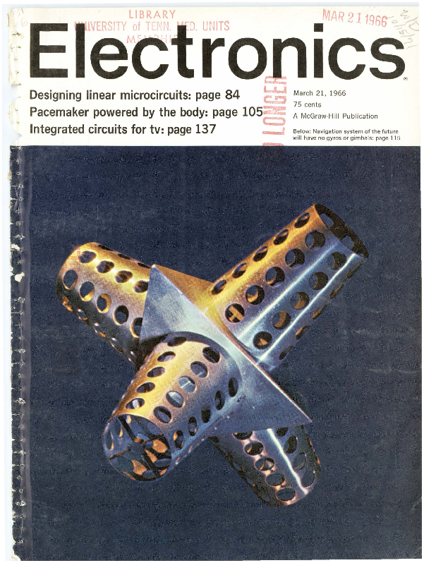
This issue of Electronics Magazine, dated March 21, 1966, delves into cutting-edge advancements in electronics. Discover articles on designing linear microcircuits, the innovative body-powered pacemaker, and the integration of circuits for television technology. Additionally, explore the future of navigation systems that aim to eliminate gyros and gimbals.
The publication also showcases new electronic instruments and components, including:
- General Radio's advanced pulse instruments like the Type 1217-C and 1398-A Pulse Generators, and the Type 1397-A Pulse Amplifier.
- Hewlett-Packard's versatile 2590B Microwave Frequency Converter for measurements up to 15 GHz and the 141A Storage Scope with variable persistence.
- Sprague Electric Company's Metfilm 'A' capacitors, offering improved reliability and smaller size, and their Metanet resistor networks.
- El-Menco capacitors, highlighting their high reliability in television sets.
- Machlett Laboratories' ML-8618 triode for high-power transmitter applications.
- Granger Associates' balun transformers for efficient HF antenna power transmission.
Industry Insights
The magazine also features industry news, including personnel changes and technological developments. It provides a comprehensive look at the state of electronics in 1966, with contributions from leading companies and researchers.
For more information on these topics, readers are encouraged to visit the respective company websites or consult industry archives.