EVAL-ADPD144RIZ-SF (Rev. 0)
EVAL-ADPD144RIZ-SF (Rev. 0)
optical sensors, optical sensing devices, optical mixed signal devices, optimal heart rate,
"optical sensors, optical sensing devices, optical mixed signal devices, optimal heart rate, "
EVAL-ADPD144RIZ-SF User Guide
the software package download for instructions on updating the EVAL-ADPDUCZ firmware 16737-002 16737-005 16737-006. UG-1272 EVAL-ADPD144RIZ-SF User Guide Rev. 0 | Page 4 of 10 ACQUIRING DATA RUNNING THE APPLICATIONS WAV…
the software package download for instructions on updating the EVAL-ADPDUCZ firmware 16737-002 16737-005 16737-006. UG-1272 EVAL-ADPD144RIZ-SF User Guide
Full PDF Document

If the inline viewer fails, it will open the original document in compatibility mode automatically. You can also open the file directly.
Extracted Text
EVAL-ADPD144RIZ-SF User Guide
UG-1272
One Technology Way � P.O. Box 9106 � Norwood, MA 02062-9106, U.S.A. � Tel: 781.329.4700 � Fax: 781.461.3113 � www.analog.com
Evaluating the ADPD144RI PPG Optical Sensor Module with Integrated Red/IR Emitters and AFE
FEATURES
GENERAL DESCRIPTION
Supports the detection of UART UDP transfer capability ADPD144RI full configuration
Register level High level Graph view Time graph Frequency graph
EVALUATION KIT CONTENTS
EVAL-ADPD144RIZ-SF evaluation boards
ADDITIONAL EQUIPMENT NEEDED
PC running Windows� 7 or Windows 10 operating system EVAL-ADPDUCZ microcontroller board
ONLINE RESOURCES
ADPD144RI data sheet Applications Wavetool software package
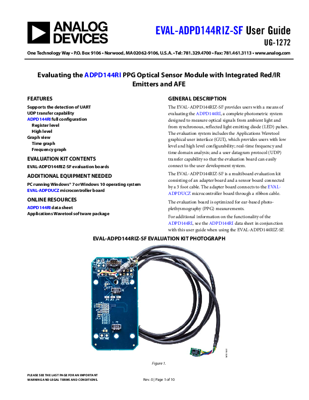
The EVAL-ADPD144RIZ-SF provides users with a means of evaluating the ADPD144RI, a complete photometric system designed to measure optical signals from ambient light and from synchronous, reflected light emitting diode (LED) pulses. The evaluation system includes the Applications Wavetool graphical user interface (GUI), which provides users with low level and high level configurability; real-time frequency and time domain analysis; and a user datagram protocol (UDP) transfer capability so that the evaluation board can easily connect to the user development system.
The EVAL-ADPD144RIZ-SF is a multiboard evaluation kit consisting of an adapter board and a sensor board connected by a 3 foot cable. The adapter board connects to the EVALADPDUCZ microcontroller board through a ribbon cable.
The evaluation board is optimized for ear-based photoplethysmography (PPG) measurements.
For additional information on the functionality of the ADPD144RI, see the ADPD144RI data sheet in conjunction with this user guide when using the EVAL-ADPD144RIZ-SF.
EVAL-ADPD144RIZ-SF EVALUATION KIT PHOTOGRAPH
16737-001
PLEASE SEE THE LAST PAGE FOR AN IMPORTANT WARNING AND LEGAL TERMS AND CONDITIONS.
Figure 1. Rev. 0 | Page 1 of 10
UG-1272
TABLE OF CONTENTS
Features .............................................................................................. 1 Evaluation Kit Contents................................................................... 1 Additional Equipment Needed ....................................................... 1 Online Resources .............................................................................. 1 General Description ......................................................................... 1 EVAL-ADPD144RIZ-SF Evaluation Kit Photograph .................. 1 Revision History ............................................................................... 2 Getting Started .................................................................................. 3
Installing the Applications Wavetool ......................................... 3 Connecting the EVAL-ADPDUCZ Microcontroller Board and the EVAL-ADPD144RIZ-SF................................................ 3
REVISION HISTORY
2/2019--Revision 0: Initial Version
EVAL-ADPD144RIZ-SF User Guide
Checking the USB Serial Connection in Windows ..................3 Updating the EVAL-ADPDDUCZ Firmware............................3 Acquiring Data...................................................................................4 Running the Applications Wavetool.............................................4 USB UART Connection................................................................4 Selecting the Proper View ............................................................4 Load Configuration ......................................................................4 Optimizing and Running the ADPD144RI ...............................5 Evaluation Board Schematics and Artwork...................................6
Rev. 0 | Page 2 of 10
EVAL-ADPD144RIZ-SF User Guide
GETTING STARTED
INSTALLING THE APPLICATIONS WAVETOOL
Download the Applications Wavetool software package from the EVAL-ADPD144RIZ-SF product page. Unzip the folder and run the Applications Wavetool executable file. Follow the prompts, beginning with the Applications Wavetool Setup window shown in Figure 2 for software installation. The Applications Wavetool is periodically updated to add features and improve performance. It is recommended that customers use the latest revision to take advantage of new features and performance.
UG-1272
CHECKING THE USB SERIAL CONNECTION IN WINDOWS
Ensure that the communications port (COM port) driver is installed correctly. To verify proper installation, go to Control Panel > All Control Panel Items > System > Device Manager, as shown in Figure 3. In this case, the proper COM port choice is USB Serial Port (COM16). The EVAL-ADPDUCZ microcontroller board uses an FT232 USB, universal asynchronous receiver transmitter (UART) IC. If the USB driver does not install properly, refer to the FTDI driver installation guide that corresponds with the operating system in use.
16737-005
Figure 2. Applications Wavetool Setup
CONNECTING THE EVAL-ADPDUCZ MICROCONTROLLER BOARD AND THE EVALADPD144RIZ-SF
Connect the USB cable to the EVAL-ADPDUCZ and the ribbon cable to the EVAL-ADPD144RIZ-SF. Switch the power switch to the ON position.
When the power switch is in the ON position, the LED near the power switch illuminates, indicating that the EVAL-ADPDUCZ microcontroller board is on. When the USB cable is connected to the EVAL-ADPDUCZ, the second LED near the power switch illuminates, indicating that the on-board battery is charging.
16737-002
Figure 3. USB Serial Port in Windows 7
UPDATING THE EVAL-ADPDDUCZ FIRMWARE
The EVAL-ADPDUCZ microcontroller board may have an older version of the firmware installed during manufacturing. If the user receives the message shown in Figure 4 when trying to connect to the Applications Wavetool, the EVAL-ADPDUCZ must be updated.
Figure 4. Firmware Out of Date Warning Prompt
Refer to the Applications Wavetool user guide that is provided in the software package download for instructions on updating the EVAL-ADPDUCZ firmware
16737-006
Rev. 0 | Page 3 of 10
UG-1272
ACQUIRING DATA
RUNNING THE APPLICATIONS WAVETOOL
To start the Applications Wavetool, navigate to the Start menu > Analog Devices > ApplicationsWaveTool and click ApplicationsWavetool.
USB UART CONNECTION
To establish the connection, follow the menu path Connection > Connect > UART Bridge.
EVAL-ADPD144RIZ-SF User Guide
SELECTING THE PROPER VIEW
The ADPD144RI is intended for nonwrist-based PPG measurements. Click the ADPD Device data view (see Figure 6) to open a window that allows the user to run the ADPD144RI device and collect data (see Figure 7).
16616-009 16737-014
Figure 5. UART Connect
Select the proper COM port to connect the Applications Wavetool to the device. If connection via Bluetooth� is required, or if there are any other connection issues, refer to the Applications Wavetool user guide that is provided in the software package download.
Figure 6. Click ADPD Device
LOAD CONFIGURATION
In the upper right corner of the data view window, click ADPD Config to open the ADPD Config window shown in Figure 7. Click Load DCFG to choose a configuration file. For PPG measurements, choose the 144RI_earbud.dcfg configuration file.
16737-015
Figure 7. ADPD Config View Rev. 0 | Page 4 of 10
EVAL-ADPD144RIZ-SF User Guide
OPTIMIZING AND RUNNING THE ADPD144RI
After the configuration file is loaded, the settings can be further optimized using the ADPD Config window shown in Figure 7. Typically, the device is set up under a certain set of conditions, such as measuring the response from a fixed reflector or measuring a PPG signal from the ear (see Figure 8). Settings can be optimized for any set of conditions by manipulating LED drive currents, transimpedance amplifier (TIA) gain, and
UG-1272
analog front end (AFE) timing. Another option is to use different operating modes that can be more optimal for a specific set of conditions, such as using float mode for a low current transfer ratio (CTR). For information on optimization of the ADPD144RI, refer to the ADPD144RI data sheet. For functional descriptions of the Applications Wavetool, refer to the Applications Wavetool user guide provided in the software package download.
16737-016
Figure 8. Example of a PPG Signal
Rev. 0 | Page 5 of 10
UG-1272
EVALUATION BOARD SCHEMATICS AND ARTWORK
CONNECTOR 1 (TO DAUGHTER)
CONNECTOR 1 (FROM DAUGHTER)
Figure 9. EVAL-ADPD144RIZ-SF BR-048862 Schematic Rev. 0 | Page 6 of 10
AGND
VLDO1/IOVDD VLDO2 VBOOST
CONN1_WAKE1/P1_0 CONN1_SPI1_CS1/RTC1_OPC1/P2_11 CONN1_SPI1_CLK/P1_6 CONN1_SPI1_MISO/P1_8 CONN1_ADC0_VIN1/P2_4 CONN1_SPI1_CS3/P1_10
P3
1 3 5 7 9 11 13 15 17 19
AGND
VLDO1/IOVDD VOUT__ACT VBOOST
CONN1_I2C_SDA/P0_5 CONN1_I2C_SCL/P0_ CONN1_TMR0_OUT/P014 CONN1_WAKE0/P0_15 CONN1_SPI1_CS0/P1_9 CONN1_SPI1_MOSI/P1_7
P3
2 4 6 8 10 12 14 16 18 20
VLDO2 VOUT__ACT
VOUT_CON1
JP1
A COM B
3PIN_JUMPER
MB_VLDO1/IOVDD MB_VLDO2 MB_VBOOST
AGND
J_CONN1_WAKE1/P1_0 J_CONN1_SPI1_CS1/P2_11 CONN1_SPI1_CLK/P1_6 CONN1_SPI1_MISO/P1_8 J_CONN1_ADC0_VIN1/P2_4 J_CONN1_SPI1_CS3/P1_10
P1
2 4 6 8 10 12 14 16 18 20
AGND
MB_VLDO1/IOVDD VOUT_CON1 MB_VBOOST
CONN1_I2C_SDA/P0_5 CONN1_I2C_SCL/P0_4 J_CONN1_TMR0_OUT/P0_14 J_CONN1_WAKE0/P0_15 J_CONN1_SPI1_CS0/P1_ CONN1_SPI1_MOSI/P1_7
P1
1 3 5 7 9 11 13 15 17 19
DF40C-20DP-0.4V(51)
DF40C-20DP-0.4V(51)
SAME NAMES AS GLUE MOTHERBOARD
EEPROM MEMORY
CONN1_I2C_SCL/P0_4
VLDO2
U10 VCC SCL SDA VSS
CONN1_I2C_SDA/P0_5
M24C16-DFCU6TP/K
AGND
P2 2 4 6 8 10 12 14 16 18 20
DF40C-20DP-0.4V(51)
P2 1 3 5 7 9 11 13 15 17 19
DF40C-20DP-0.4V(51)
I2C_SDA/P0_5 I2C_SCL/P0_4
DF40C-20DP-0.4V(51)
R29
CONN1_I2C_SDA/P0_5
0 DNI
R30
CONN1_I2C_SCL/P0_4
0 DNI
PW1 VLDO1/IOVDD
PW2
VLDO2
TP1
VLDO1/IOVDD VLDO1/IOVDD
1 2
VLDO2 VBOOST
VOUT_CON1 VBOOST
3 4 5 6
7
AGND
T_CONN1_WAKE1/P1_0 CONN1_I2C_SDA/P0_5
T_CONN1_SPI1_CS1/RTC1_OPC1/P2_11 CONN1_I2C_SCL/P0_4
CONN1_SPI1_CLK/P1_6 T_CONN1_TMR0_OUT/P014
CONN1_SPI1_MISO/P1_8 T_CONN1_WAKE0/P0_15
T_CONN1_ADC0_VIN1/P2_4 T_CONN1_SPI1_CS0/P1_9
T_CONN1_SPI1_CS3/P1_10 CONN1_SPI1_MOSI/P1_7
8 9 10 11 12 13 14 15 16 17 18 19 20
T_CONN1_WAKE1/P1_0
CONN1_WAKE1/P1_0
R12
0
T_CONN1_SPI1_CS1/RTC1_OPC1/P2_11
CONN1_SPI1_CS1/RTC1_OPC1/P2_11 R14 0
T_CONN1_TMR0_OUT/P014
CONN1_TMR0_OUT/P014
R16
0
T_CONN1_WAKE0/P0_15
TSW-110-08-G-D
CONN1_WAKE0/P0_15
R18
1.8V ADJ_VDD PB0 (SEL)
INT
VLDO2 VBOOST
RIBBON_PB0 CONN1_I2C_SDA/P0_5
RIBBON_INT CONN1_SPI1_CLK/P1_6 CONN1_SPI1_MOSI/P1_7
PR1
1
VLDO2
3
VBOOST
5
3.3V VDD_3V
R3
0
7
PB1 (ACC) CONN1_I2C_SCL/P0_4
9
RIBBON_PB1
11
CONN1_SPI1_CS0/P1_9
13
CONN1_SPI1_MISO/P1_8
15
PR1
2 4 6 8 10 12 14 16
0
T_CONN1_WAKE1/P1_0 RIBBON_INT T_CONN1_TMR0_OUT/P014
JP9
A COM B
T_CONN1_ADC0_VIN1/P2_4
CONN1_ADC0_VIN1/P2_4
R20
0
3PIN_JUMPER
T_CONN1_SPI1_CS0/P1_9
FTSH-108-01-L-D-K AGND
FTSH-108-01-L-D-K
CONN1_SPI1_CS0/P1_9
R22
AGND
JP13
0
T_CONN1_WAKE0/P0_15 RIBBON_PB0
JP8
A COM
JP7
T_CONN1_SPI1_CS1/RTC1_OPC1/P2_11 A
RIBBON_PB1
COM
T_CONN1_SPI1_CS0/P1_9
B
T_CONN1_WAKE0/P0_15 RIBBON_INT
A COM B
3PIN_JUMPER
T_CONN1_SPI1_CS3/P1_10
B
CONN1_SPI1_CS3/P1_10
R24
3PIN_JUMPER
3PIN_JUMPER
0
R13
J_CONN1_WAKE1/P1_0
0
R15 J_CONN1_SPI1_CS1/P2_11 0
R17 J_CONN1_TMR0_OUT/P0_14 0
R19 J_CONN1_WAKE0/P0_15 0
R21 J_CONN1_ADC0_VIN1/P2_4 0
R23 J_CONN1_SPI1_CS0/P1_9 0
R25 J_CONN1_SPI1_CS3/P1_10 0
PW3
VBOOST
PW4
PW6 VLD03
PW7
DF40C-20DP-0.4V(51)
JP2 0
JP3 0
JP4 0
MB_VLDO1/IOVDD C1
TBD0805 MB_VLDO2
C2 TBD0805 MB_VBOOST
C3 TBD0805
AGND
JP6
MB_VLD03
0
C6
TBD0805
AGND
RIBBON_PB1
R27
T_CONN1_WAKE0/P0_15
0
EVAL-ADPD144RIZ-SF User Guide
16737-017
EVAL-ADPD144RIZ-SF User Guide
VLED VDD GND SCL SDA INT
VLED VDD
GND_LOCAL SCL SDA INT
VLED
VDD
R1 10k
R2 10k
SCL
SDA
C2 1�F GND_LOCAL
VDD U1
7 10 5
VLED VDD2 VDD1
SCL
SPARE PIN
SPARE PIN
6 VREF 12 SCL
9 LED1/DNC 8 LED2/DNC
SDA INT
2 11
C3 0.01�F
C4 1�F
GND_LOCAL SDA INT
LGND DGND AGND
C1
1 3 4
1�F
ADPD144RI-ACEZ
GND_LOCAL
GND_LOCAL
Figure 10. EVAL-ADPD144RIZ-SF BR-048911 Schematic
16737-018
UG-1272
16737-019
Figure 11. EVAL-ADPD144RIZ-SF BR-048911 Primary Layer
16737-021
Figure 12. EVAL-ADPD144RIZ-SF BR-048911 Secondary Layer Rev. 0 | Page 7 of 10
UG-1272
EVAL-ADPD144RIZ-SF User Guide
16737-020
Figure 13. EVAL-ADPD144RIZ-SF BR-048862 Primary Layer
16737-022
Figure 14. EVAL-ADPD144RIZ-SF BR-048862 Secondary Layer Rev. 0 | Page 8 of 10
EVAL-ADPD144RIZ-SF User Guide
UG-1272
16737-100
Figure 15. EVAL-ADPD144RIZ-SF Connected to the EVAL-ADPDUCZ Microcontroller Board
Rev. 0 | Page 9 of 10
UG-1272 NOTES
EVAL-ADPD144RIZ-SF User Guide
ESD Caution ESD (electrostatic discharge) sensitive device. Charged devices and circuit boards can discharge without detection. Although this product features patented or proprietary protection circuitry, damage may occur on devices subjected to high energy ESD. Therefore, proper ESD precautions should be taken to avoid performance degradation or loss of functionality. Legal Terms and Conditions By using the evaluation board discussed herein (together with any tools, components documentation or support materials, the "Evaluation Board"), you are agreeing to be bound by the terms and conditions set forth below ("Agreement") unless you have purchased the Evaluation Board, in which case the Analog Devices Standard Terms and Conditions of Sale shall govern. Do not use the Evaluation Board until you have read and agreed to the Agreement. Your use of the Evaluation Board shall signify your acceptance of the Agreement. This Agreement is made by and between you ("Customer") and Analog Devices, Inc. ("ADI"), with its principal place of business at One Technology Way, Norwood, MA 02062, USA. Subject to the terms and conditions of the Agreement, ADI hereby grants to Customer a free, limited, personal, temporary, non-exclusive, non-sublicensable, non-transferable license to use the Evaluation Board FOR EVALUATION PURPOSES ONLY. Customer understands and agrees that the Evaluation Board is provided for the sole and exclusive purpose referenced above, and agrees not to use the Evaluation Board for any other purpose. Furthermore, the license granted is expressly made subject to the following additional limitations: Customer shall not (i) rent, lease, display, sell, transfer, assign, sublicense, or distribute the Evaluation Board; and (ii) permit any Third Party to access the Evaluation Board. As used herein, the term "Third Party"includes any entity other than ADI, Customer, their employees, affiliates and in-house consultants.The Evaluation Board is NOT sold to Customer; all rights not expressly granted herein, including ownership of the Evaluation Board, are reserved by ADI. CONFIDENTIALITY. This Agreement and the Evaluation Board shall all be considered the confidential and proprietary information of ADI. Customer may not disclose or transfer any portion of the Evaluation Board to any other party for any reason. Upon discontinuation of use of the Evaluation Board or termination of this Agreement, Customer agrees to promptly return the Evaluation Board to ADI. ADDITIONAL RESTRICTIONS. Customer may not disassemble, decompile or reverse engineer chips on the Evaluation Board. Customer shall inform ADI of any occurred damages or any modifications or alterations it makes to the Evaluation Board, including but not limited to soldering or any other activity that affects the material content of the Evaluation Board. Modifications to the Evaluation Board must comply with applicable law, including but not limited to the RoHS Directive. TERMINATION. ADI may terminate this Agreement at any time upon giving written notice to Customer. Customer agrees to return to ADI the Evaluation Board at that time. LIMITATION OF LIABILITY. THE EVALUATION BOARD PROVIDED HEREUNDER IS PROVIDED "AS IS" AND ADI MAKES NO WARRANTIES OR REPRESENTATIONS OF ANY KIND WITH RESPECT TO IT. ADI SPECIFICALLY DISCLAIMS ANY REPRESENTATIONS, ENDORSEMENTS, GUARANTEES, OR WARRANTIES, EXPRESS OR IMPLIED, RELATED TO THE EVALUATION BOARD INCLUDING, BUT NOT LIMITED TO, THE IMPLIED WARRANTY OF MERCHANTABILITY, TITLE, FITNESS FOR A PARTICULAR PURPOSE OR NONINFRINGEMENT OF INTELLECTUAL PROPERTY RIGHTS. IN NO EVENT WILL ADI AND ITS LICENSORS BE LIABLE FOR ANY INCIDENTAL, SPECIAL, INDIRECT, OR CONSEQUENTIAL DAMAGES RESULTING FROM CUSTOMER'S POSSESSION OR USE OF THE EVALUATION BOARD, INCLUDING BUT NOT LIMITED TO LOST PROFITS, DELAY COSTS, LABOR COSTS OR LOSS OF GOODWILL. ADI'S TOTAL LIABILITY FROM ANY AND ALL CAUSES SHALL BE LIMITED TO THE AMOUNT OF ONE HUNDRED US DOLLARS ($100.00). EXPORT. Customer agrees that it will not directly or indirectly export the Evaluation Board to another country, and that it will comply with all applicable United States federal laws and regulations relating to exports. GOVERNING LAW. This Agreement shall be governed by and construed in accordance with the substantive laws of the Commonwealth of Massachusetts (excluding conflict of law rules). Any legal action regarding this Agreement will be heard in the state or federal courts having jurisdiction in Suffolk County, Massachusetts, and Customer hereby submits to the personal jurisdiction and venue of such courts. The United Nations Convention on Contracts for the International Sale of Goods shall not apply to this Agreement and is expressly disclaimed.
�2019 Analog Devices, Inc. All rights reserved. Trademarks and registered trademarks are the property of their respective owners.
UG16737-0-2/19(0)
Rev. 0 | Page 10 of 10