u-blox XPLR-AOA Bluetooth Indoor Direction Finding Explorer Kit User Guide
File info: application/pdf · 28 pages · 1.28MB
XPLR-AOA explorer kits, user guide
Bluetooth indoor direction finding
XPLR-AOA explorer kits
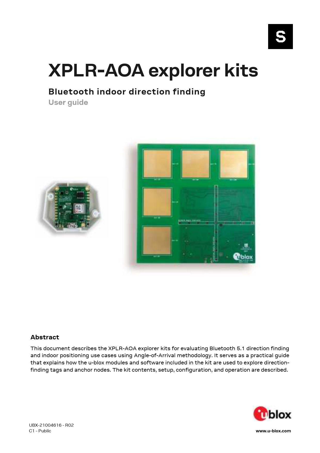
UBX-21004616 - R02 C1 - Public www.u-blox.com XPLR-AOA explorer kits Bluetooth indoor direction finding User guide Abstract This document describes the XPLR-AOA explorer kits for evaluating Bluetooth 5.1 direction findi…
Full PDF Document

If the inline viewer fails, it will open the original document in compatibility mode automatically. You can also open the file directly.
Extracted Text
XPLR-AOA explorer kits
Bluetooth indoor direction finding
User guide

Abstract
This document describes the XPLR-AOA explorer kits for evaluating Bluetooth 5.1 direction finding and indoor positioning use cases using Angle-of-Arrival methodology. It serves as a practical guide that explains how the u-blox modules and software included in the kit are used to explore directionfinding tags and anchor nodes. The kit contents, setup, configuration, and operation are described.

UBX-21004616 - R02 C1 - Public

www.u-blox.com

XPLR-AOA explorer kits - User guide

Document information

Title Subtitle Document type Document number Revision and date Disclosure restriction

XPLR-AOA explorer kits Bluetooth indoor direction finding User guide UBX-21004616 R02 C1 - Public

28-Jun-2021

This document applies to the following products:
Product name NINA-B4 XPLR-AOA-1 XPLR-AOA-2

u-blox or third parties may hold intellectual property rights in the products, names, logos and designs included in this document. Copying, reproduction, modification or disclosure to third parties of this document or any part thereof is only permitted with the express written permission of u-blox. The information contained herein is provided "as is" and u-blox assumes no liability for its use. No warranty, either express or implied, is given, including but not limited to, with respect to the accuracy, correctness, reliability and fitness for a particular purpose of the information. This document may be revised by u-blox at any time without notice. For the most recent documents, visit www.u-blox.com. Copyright � u-blox AG.

UBX-21004616 - R02 C1 - Public

Document information

Page 2 of 28

XPLR-AOA explorer kits - User guide

Contents
Document information ............................................................................................................................. 2 Contents ....................................................................................................................................................... 3 1 Product description ............................................................................................................................ 5
1.1 Kit includes ................................................................................................................................................... 6 1.2 Evaluation software.................................................................................................................................... 6 1.3 System requirements ................................................................................................................................ 6 2 Bluetooth direction finding .............................................................................................................. 7 2.1 Technology ................................................................................................................................................... 7
2.1.1 Angle of Arrival (AoA) ......................................................................................................................... 7 2.1.2 Angle of Departure (AoD) .................................................................................................................. 8 2.1.3 Angles of measurement .................................................................................................................... 8 3 XPLR-AOA anchor nodes and tags ................................................................................................ 9 3.1 Introduction.................................................................................................................................................. 9 3.2 Overview........................................................................................................................................................ 9 3.3 C211 anchor nodes...................................................................................................................................10 3.3.1 Overview .............................................................................................................................................10 3.3.2 Connectors.........................................................................................................................................10 3.3.3 Flashing ..............................................................................................................................................13 3.3.4 Configuring the board......................................................................................................................14 3.4 C209 tags ...................................................................................................................................................14 3.4.1 Overview .............................................................................................................................................14 3.4.2 Software and flashing......................................................................................................................16 4 System setup .................................................................................................................................... 17 4.1 Anchor node configuration......................................................................................................................17 4.2 Tag configuration......................................................................................................................................17 4.2.1 Configuring advertising interval ....................................................................................................17 4.2.2 Enabling/disabling advertising ......................................................................................................18 4.3 Restore Eddystone Instance ID..............................................................................................................18 5 Running system................................................................................................................................ 19 Appendix .................................................................................................................................................... 20 A Anchor node AT commands .......................................................................................................... 20 A.1 Direction finding enable +UDFENABLE................................................................................................20 A.1.1 Description .........................................................................................................................................20 A.1.2 Syntax .................................................................................................................................................20 A.1.3 Defined values ...................................................................................................................................20 A.2 Direction finding filter +UDFFILT ..........................................................................................................20 A.2.1 Description .........................................................................................................................................20 A.2.2 Syntax .................................................................................................................................................20 A.2.3 Defined values ...................................................................................................................................21 A.2.4 Notes ...................................................................................................................................................21

UBX-21004616 - R02 C1 - Public

Contents

Page 3 of 28

XPLR-AOA explorer kits - User guide
A.3 Configure direction finding +UDFCFG ..................................................................................................21 A.3.1 Description .........................................................................................................................................21 A.3.2 Syntax .................................................................................................................................................21 A.3.3 Defined values ...................................................................................................................................22
A.4 Angle calculation event +UUDF..............................................................................................................23 A.4.1 Description .........................................................................................................................................23 A.4.2 Syntax .................................................................................................................................................23 A.4.3 Defined values ...................................................................................................................................23
A.5 Other supported AT commands ............................................................................................................23 B Glossary .............................................................................................................................................. 24 C Limitations......................................................................................................................................... 24 D C209 schematics.............................................................................................................................. 25 Related documentation......................................................................................................................... 26 Revision history ....................................................................................................................................... 27 Contact....................................................................................................................................................... 28

UBX-21004616 - R02 C1 - Public

Contents

Page 4 of 28

1 Product description

A Bluetooth "tag" is a small, thin device that can attached to any object to track its whereabouts. An "anchor node" calculates the position of the tag. Bluetooth tags can attach to keys, wallets, purses, and other personal property.
u-blox direction finding solutions that leverage this Bluetooth direction finding technology can be evaluated using two separate explorer kits, as described in Table 1.

Model XPLR-AOA-1

Order code XPLR-AOA-1

XPLR-AOA-2 XPLR-AOA-2

Description
Bluetooth 5.1 direction finding explorer kit for evaluating Bluetooth 5.1 direction finding using Angle-of-Arrival methodology. The kit includes a single C211 application board and one C209 tag: � C211 application boards include a NINA-B411 module and an antenna array that
represents the anchor node for direction finding, using Angle-of-Arrival methodology. u-connectLocate direction finding software installed on NINA-B411 delivers angle information for tracked tags to a listening host. � C209 tags are based on the open CPU NINA-B406 module variant. The tags run on custom tag software that advertise Eddystone beacons with appended with Constant Tone Extensions (CTE). The CTE data is used by C211 application board to calculate the position of the C209 tag.
Bluetooth 5.1 direction finding explorer kit for evaluating and developing indoor positioning use cases, using Angle-of-Arrival methodology. The kit includes a four C211 application boards, four C209 tags and positioning engine client software: � C211 application boards include a NINA-B411 module and an antenna array that
represents the anchor node for direction finding using Angle-of-Arrival methodology. u-connectLocate direction finding software installed on NINA-B411 delivers angle information for tracked tags to a listening host. � C209 tags are based on the open CPU NINA-B406 module variant. The tags run on custom tag software that advertise Eddystone beacons with appended with Constant Tone Extensions (CTE). The CTE data is used by C211 application board to calculate the position of the C209 tag.

Table 1: u-blox direction-finding explorer kits and ordering codes
 For further information about the positioning engine client software for Windows, see also the
indoor positioning guide [2] .

Figure 1: u-blox direction-finding explorer kits comprising C211 application board(s) and C209 tag(s)

UBX-21004616 - R02 C1 - Public

Contents

Page 5 of 28

1.1 Kit includes
XPLR-AOA-1 direction finding explorer kit for out-of-the-box AoA evaluation includes:
� C211 antenna board with NINA-B411 Bluetooth LE module � C209 tag with NINA-B406 Bluetooth LE module � u-connectLocate direction finding software (from u-blox.com) � C209 tag software example (from Github)
XPLR-AOA-2 indoor positioning explorer kit for out-of-the-box evaluation of indoor positioning includes:
� Four C211 antenna boards with NINA-B411 module � Four C209 tags with NINA-B406 module � u-connectLocate direction finding software (from u-blox.com) � C209 tag software example (from Github) � Positioning engine software example to run on a PC
1.2 Evaluation software
Several evaluation packages are available:
� u-connectLocate delivers angle information for tracked tags to a listening host. Customers install u-connectLocate software on the NINA B411 module mounted on the C211 integration board. C211 integration boards are delivered with bootloader software only.
� s-center software Bluetooth and Wi-Fi evaluation software provides a powerful and easy-to-use tool for evaluating, configuring, and testing u-blox short range modules
� Sample positioning-engine client that runs on a local Windows workstation (XPLR-AOA-2 only)
1.3 System requirements
� PC with USB interface � Operating system: Windows 7 onwards

UBX-21004616 - R02 C1 - Public

Contents

Page 6 of 28

2 Bluetooth direction finding
Bluetooth direction finding provides a relatively inexpensive and flexible approach to developing location-related applications for both in indoor and outdoor environments. Examples of applications for which Bluetooth direction finding technology is most suitable include: � Asset tracking � Navigation � Wayfinding � Proximity/Direction detection
2.1 Technology
Bluetooth direction finding can be implemented using two different methods, Angle of Arrival (AoA) and of Departure (AoD). In each case, protocol-specific control information and user data, transmitted as Bluetooth Protocol Data Units (PDU), are appended with direction-finding data known as Constant Tone Extension (CTE). This additional direction-finding data is appended to the end of the packages, as shown in Figure 2.
Figure 2: Bluetooth PDU with Constant Tone Extension
2.1.1 Angle of Arrival (AoA)
In AoA systems, the receiver has an antenna array with multiple antennas. The receiver calculates the phase shift between these antennas to detect the direction of the tag that it is tracking. An overview of a system using this method of direction finding is shown in Figure 3.

Figure 3: Angle of Arrival (AoA) system architecture

UBX-21004616 - R02 C1 - Public

Contents

Page 7 of 28

2.1.2 Angle of Departure (AoD)
In AoD systems, the transmitter has multiple antennas. The receiver calculates the phase difference between these antennas to determine the direction to the transmitter. By using this data in combination with angle data from other transmitters, the receiver can estimate its position. An overview of a system using this method of direction finding is shown in in Figure 4.
Figure 4: Angle of Departure (AoD) system architecture
2.1.3 Angles of measurement
In both AoA and AoD systems, the reported angles of the azimuth and elevation measurements are compared against a reference plane, as shown in Figure 5.

Figure 5: Azimuth and elevation angles
For further information about Bluetooth direction finding, see the u-blox webinar "Bluetooth for High Precision Indoor Positioning" available on the u-blox webinar page [8] and Bluetooth SIG technical overview [1].

UBX-21004616 - R02 C1 - Public

Contents

Page 8 of 28

3 XPLR-AOA anchor nodes and tags
3.1 Introduction
Both XPLR-AOA-1 and XPLR-AOA-2 explorer kits include both Bluetooth anchor nodes and tags.
 Although this chapter generally describes these nodes and tags in the context of the XPLR-AOA-1
direction finding system, the concepts it describes are equally applicable to the XPLR-AOA-2 indoor positioning explorer kit. For information about the XPLR-AOA-2 positioning engine, setup, and configuration, see also the indoor positioning application note [2].
3.2 Overview
u-blox direction finding solutions are comprised of C211 anchor nodes C209 tags, as shown in Figure 6. See also Kit includes. u-blox direction-finding solution supports the Angle of Arrival (AoA) methodology.
C211 anchor nodes are based on NINA-B4 modules that include support for direction finding. Anchor nodes are based on NINA-B411 u-connectXpress functionality, whereas C209 tags are based on NINA-B406 open CPU architecture. For more information about these short-range Bluetooth modules, see also the respective data sheets [13][14] and product pages [2].
Figure 6 shows several anchor nodes and a host that uses the combined information from the anchor nodes to calculate the position of the tag. For simple direction finding one anchor node is sufficient.

Figure 6: XPLR-AOA direction-finding solution showing four anchor points tracking a single tag

UBX-21004616 - R02 C1 - Public

Contents

Page 9 of 28

3.3 C211 anchor nodes
3.3.1 Overview
C211 application boards are equipped with a NINA-B411 module and an antenna array. These boards fulfill the role of the anchor node in the XPLR-AOA direction-finding solutions. Anchor nodes run AT command-based u-connectLocate direction finding software, which delivers AoA data for tracked beacons to a listening host. Data is transmitted to the host as events over the NINA-B411 UART interface. See also Anchor node AT commands.
� C211 has an array of five antennas that are used to detect the phase shift for the direction finding � in both horizontal and vertical levels.
� C211 also has an LED array in the form of a cross. The LEDs indicate the direction of tracked beacons. In instances where the anchor node tracks several beacons, the LED array tracks the first C209 tag that is discovered.

Figure 7: C211 antenna side
The C211 board dimensions are 115 (h) x 114 (w) mm.
3.3.2 Connectors
3.3.2.1 UART
The UART connection must be configured for USB connection with jumpers connecting pins 3 to 5 and 4 to 6 on connector J5, as shown in Figure 8.

Figure 8: Jumper settings for UART connection over USB

UBX-21004616 - R02 C1 - Public

Contents

Page 10 of 28

3.3.2.2 Arduino interface
C211 boards contain an Arduino compatible interface that can be used to connect, for example, an ODIN-W2 EVK to enable wireless communication over UDP. For further information about UDP, see the u-connectXpress software user guide [16].
The Arduino connectors, J1, J3 and J4, are shown in Figure 9.

Figure 9: C211 with Arduino connectors marked
3.3.2.2.1 Pinout The pinout of the Arduino compatible connectors is described in EVK-ODIN-W2 wireless gateway configuration.

Connector Pin

J1

1

2

3

4

5

6

7

8

J3

1

2

3

4

5

6

7

Name
NC IOREF RESET 3V3
5V0 GND GND VIN NC NC RXD NC NC D5 NC

Description
Not connected IO reference voltage Reset Regulated 3.3 V net. This net is supplied by the board and is always powered as long as a power source is connected. 5 V supply Ground Ground External power supply via ODIN-W2 Not connected Not connected Can be connected to NINA-B411 GPIO_22/UART_TXD by populating jumper J5 pin [1-3] Not connected Not connected Not Connected. Can be connected to NINA-B411 GPIO_32 by populating position R68. Not connected

UBX-21004616 - R02 C1 - Public

Contents

Page 11 of 28

Connector Pin Name Description

8

NC

Not connected

J4

1

TXD/D8 Can be connected to NINA-B411 GPIO_23/UART_RXD by populating jumper J5 pin [2-4]

Not Connected. Can be connected to NINA-B411 GPIO_33 by populating position R70.

2

D9

Not Connected. Can be connected to NINA-B411 GPIO_46 by populating position R69.

3

NC

Not connected

4

NC

Not connected

5

NC

Not connected

6

D13

Not Connected. Can be connected to NINA-B411 GPIO_45 by populating position R67

7

GND

Ground

8

NC

Not connected

9

SDA

Not Connected. Can be connected to NINA-B411 GPIO_4/I2C SDA by populating position R66.

10 SCL

Not Connected. Can be connected to NINA-B411 GPIO_5/I2C SDL by populating position R65.

Table 2: Pin out of Arduino connectors

3.3.2.2.2 Connecting EVK-ODIN-W2 for wireless communication

When connecting an EVK-ODIN-W2 evaluation kit for wireless communication, you need to redirect the TX channel from the C211 anchor to EKV-ODIN-W2 by modifying the jumpers on the J5 connector, as shown in Figure 10. This connects the UART TX pin on the C211 to UART1 RX on the EVK-ODINW2. See also the EVK-ODIN-W2 user guide [15].

Figure 10: Redirecting C211 UART TX to Arduino connector
3.3.2.2.3 Power supply
When mounting an ODIN-W2 EVK, the application board is powered through the ODIN-W2 EVK USB contact. No other power supply to the C211 board is needed.
3.3.2.3 EVK-ODIN-W2 wireless gateway configuration
For C211 wireless communication though an EVK-ODIN-W2, the EVK must first be configured as a wireless UDP gateway. In this configuration the EVK can:
� Connect to a Wi-Fi network � Automatically connect to the UDP server at "server_ip" and "udp_port" � Startup in data mode � Set the UART to 1 Mbps with no flow control

UBX-21004616 - R02 C1 - Public

Contents

Page 12 of 28

1. Enter the following commands to setup EVK-ODIN-W2 as a wireless UDP gateway:
 Replace "ssid", "password" and "server_ip" and "udp_port" with suitable values for your network.
AT+UWSC=0,0,1 AT+UWSC=0,2,"ssid" AT+UWSC=0,5,2 AT+UWSC=0,8,"password" AT+UWSC=0,100,2 AT+UWSC=0,107,0 AT+UWSC=0,300,0 AT+UWSC=0,301,1 AT+UWSCA=0,1 AT+UWSCA=0,3 AT+UDDRP=0,"udp://server_ip:udp_port/",2 AT+UMSM=1 AT+UMRS=1000000,2,8,1,1,0 AT&W AT+CPWROFF
2. After the configuration it is also necessary to remove the J13 and J22 jumpers on the EVK-ODIN-W2 that selects UART1/UART3, as shown in Figure 12. This directs the UART signals to the Arduino-compatible interface.

Figure 11: UART selection jumpers to be removed on ODIN-W2 EVK

3. On C211, set the UART baud rate and other interface settings to 1 Mbps, with no flow control:
AT+UMRS=1000000,2,8,1,1,0 AT&W AT+CPWROFF
3.3.3 Flashing
Other than the bootloader, C211 boards are delivered without software.
Follow the procedure outlined below to flash the board over the UART connection.
1. Download the u-connectLocate software container from www.u-blox.com The Newt manager flashing tool (newtmgr) used to install u-connectLocate software is included in the u-connectLocate download container. The tool can also be retrieved from the mynewt download site [10]. See also the Newt Manager Guide [10].
2. Use Newt Manager to install u-connectLocate on the NINA-B411 module:
newtmgr --conntype=serial --connstring="COMXX,baud=115200" image upload <binary image>

UBX-21004616 - R02 C1 - Public

Contents

Page 13 of 28

3. Press the reset button to reset the application board or reset it with newtmgr:
newtmgr --conntype=serial --connstring="COMXX,baud=115200" reset
 As there is no software to boot during the initial startup, the NINA-B411 module automatically
enters the software download mode For future updates of NINA-B41 u-connectLocate software the bootloader must be manually set in software upload mode by pressing the SW2 button while resetting the board.
3.3.4 Configuring the board
When connecting to the USB port on the C211, a serial port (COM port on Windows) is available on the host. Connect the COM port to a terminal emulator or use the s-center tool [7] to initially configure the port settings:
� 115200 kbps � 8 data bits, no parity, 1 stop bit (8N1) � Flow control enabled using RTS/CTS
Having configured the COM port, configure the C211 using AT commands. The appropriate AT commands for configuring direction finding through the C211 anchor nodes are described in Appendix A.
 Although s-center does not support specific direction-finding AT commands using buttons, it is
possible to configure the COM port as a terminal for use with AT commands.
Due to the large amount of data received over the UART it may be advisable to increase the baud rate over the UART interface. In the following command example the baud rate is set to 1 Mbps using the command AT+UMRS.
AT+UMRS=1000000,1,8,1,1,1
For further information command AT+UMRS, see also the u-connectXpress AT command manual [5].
3.4 C209 tags
3.4.1 Overview
C209 tags are based on the open CPU NINA-B406 module variant. The tags run on custom tag software that advertises as an Eddystone beacon with a Constant Tone Extension added to the advertising packets. This CTE is used by the u-connectLocate direction finding software that runs on the C211 application board to calculate the Angle of Arrival.
The namespace included in the transmitted Eddystone-UID beacon is 0x4E494E412D4234544147 and the instance id is based on the MAC address of the NINA-B406 found on the module QR code label. See also Restore Eddystone Instance ID.
C209 tags are powered by a single CR2032 battery (not included) or through the USB connector.
C209 tags includes a versatile sensor node that comprises several sensors for use in a multitude of different applications. The on-board sensors include:
� LIS2DW12 accelerometer � APDS-9306 ambient light sensor � BME280 humidity, pressure, and temperature sensor

UBX-21004616 - R02 C1 - Public

Contents

Page 14 of 28

The main components of any C209 tag are shown in Figure 12.

Figure 12: C209 main functional components
The important pin definitions on the C209 application board are described in Table 3.

No.

Name

I/O Description

Remarks

GPIO_1

RED

O

RED system status signal

Active low

GPIO_2

LIS_INT

I

Interrupt signal from Ambient Light

Sensor

GPIO_7

GREEN

O

GREEN system status signal

Active low

GPIO_8

BLUE

O

BLUE system status signal

Active low

GPIO_18 SWITCH_2 I

Switch_2 button

Active low

GPIO_20 UART_RTS O

UART request to send control signal Used only when hardware flow control is enabled

GPIO_21 UART_CTS I

UART clear to send control signal

Used only when hardware flow control is enabled

GPIO_22 UART_TXD O

UART data output

GPIO_23 UART_RXD I

UART data input

GPIO_42 LIS_INT

I

Interrupt signal from accelerometer

Table 3 Important pin definitions on the C209

For more information about programming the module, see also the NINA-B4 system integration manual [6] and NINA-B40 data sheet [13]. See also C209 schematics.

 Although the sensors on the C209 application board are not used in the latest direction-finding
tag software from u-blox, the sensors can be utilized in any customer application.

UBX-21004616 - R02 C1 - Public

Contents

Page 15 of 28

3.4.2 Software and flashing
C209 tags are delivered with bootloader software only and do not include the tag software (from Github) needed for the device to advertise Bluetooth beacons to C211 anchor nodes.
The bootloader on C209 tags is different than that supplied on C211anchor nodes, and the nrfutil [11] flashing tool is needed to install the open-source tag software (from Github). C209 tag software is available from the u-blox open CPU repository [12].
Flash C209 using the following command:
 Replace COMXX with the appropriate COM port for your system.
nrfutil dfu serial -pkg app.zip -p COMXX -b 115200 -fc 1
The bootloader needs to be manually set in the software "upload" mode by pressing the SW2 button (see Figure 13) on the C209 while resetting the board.
The C209 can also be flashed using a debugger, using the 10-pin debugger contact available on the PCB.

UBX-21004616 - R02 C1 - Public

Contents

Page 16 of 28

4 System setup
4.1 Anchor node configuration
By default, the C211 Anchor Point comes pre-configured to track all u-blox tags. The u-blox tags advertise with the Eddystone namespace 0x4E494E412D4234544147, which is default on the C211 to track. So, if you are only using the u-blox supplied XPLR-AOA kit, no configuration is needed.
Each anchor node can be configured with beacons to track. An example for how to set up the anchor to track two tags is shown below:
AT+UDFFILT=2,2,"6E616D65737061636578" At+UDFFILT=1,2,"CCF9578E0D8A","CCF9578E0D8B"
AT+UDFENABLE=1 (Tracking is enabled by default, so this is optional)
These commands set up the anchor to track the two tags with the given MAC addresses in the Eddystone name space (6E616D65737061636578) used by the tags. The sequence described above reflects the most simplistic use case. Further configuration is possible using the AT+UDFCFG command. See also Configuration direction finding +UDFCFG.
The settings shall be saved using the AT&W command, followed by a restart (AT+CPWROFF).
4.2 Tag configuration
4.2.1 Configuring advertising interval
Press the SW2 button on the C209 to change the advertising interval. The default interval at startup is 20 milliseconds
When SW2 is pressed, the advertising interval cycles through [20, 100, 1000] milliseconds. For best performance, it is advisable to use the default 20 ms advertising interval.

Figure 13: C209 with cover and SWITCH_2 marked

UBX-21004616 - R02 C1 - Public

Contents

Page 17 of 28

C209 tags are simply configured over the UART interface using AT commands. The AT commands that can be used to configure the interface are described in Table 4.

Command AT+UMLA=1 AT+GMM AT+TXPWR=<valid_tx_power>

Description Read Local MAC address Read the model identifier, will be NINA-B4-TAG <valid_tx_power> can be one of: -40, -30, -20, -16, -12, -8, -4, 0, 2, 3, 4, 5, 6, 7, 8 (dBm)

Table 4 C209 AT commands

 For +TXPWR to take effect the software must be reset, by pressing the reset button or power cycling
the module. The configuration is persistently stored in flash.

All commands are echoed and responded with either \r\nOK\r\n or \r\nERROR\r\n, and should be terminated with \r.

 The UART interface is available for 10 seconds after reset with the settings 115200 bps, with no
flow control.

4.2.2 Enabling/disabling advertising
Press and hold the C209 button for ~3 seconds to enable/disable advertising. If the tag is advertising, press and hold the button to stop it advertising. The onboard RGB LED blinks blue when advertising is enabled. The blinking interval correlates to the advertising interval.

4.3 Restore Eddystone Instance ID
All u-blox modules are delivered with a u-blox MAC address, which is written into the UICR register.
If the MAC address is accidentally erased, for example during a reflash of the software, this information is lost. If this happens, the Eddystone Instance ID transmitted in the C209 advertising beacon will not match the MAC address of the module. To correct this:
4. Scan the QR code on the module label. The information in the code includes a code that includes the MAC address (shown here in bold): H85(CCF9578E0D89)0400.
5. Enter these commands to reinstate the MAC address CCF9578E0D89 into the UICR of the module:
nrfjprog --memwr 0x10001080 --val 0x8E57F9CC nrfjprog --memwr 0x10001084 --val 0xFFFF890D

Another example for which the MAC address given in the scan code is 0123456789AB:
nrfjprog --memwr 0x10001080 --val 0x67452301 nrfjprog --memwr 0x10001084 --val 0xFFFFAB89
6. After writing the MAC address, reset the module. The module now transmits the correct Eddystone Instance ID for the C209 tag.

UBX-21004616 - R02 C1 - Public

Contents

Page 18 of 28

5 Running system
Once the system is setup, each anchor reports, over the serial port connection, angle calculation events (+UUDF) when it detects a beacon:
+UUDF: CCF9578E0D8A,-42,20,0,-43,37,"CCF9578E0D89","", 15869 +UUDF: CCF9578E0D8B,-41,10,4,-42,38,"CCF9578E0D89","",15892 +UUDF: CCF9578E0D8A,-42,-10,2,-43,39,"CCF9578E0D89","",15921
...
The data reported in this event can be used to estimate a position of the tracked beacon.
The parameters of the +UUDF event are (in order from left to right):
� Eddystone instance ID � RSSI of 1st polarization � Azimuth angle � Elevation angle � RSSI of 2nd polarization � The advertising channel where the advertisement was found. The advertisement channel is one of
the normal Bluetooth low energy advertisement channels (37, 38 or 39) � Anchor ID as set by AT+UDFCFG tag 4 (see appendix A.3 for more details) � User defined strings as set by AT+UDFCFG tag 2. For more details. See also Configure direction
finding +UDFCFG. � Timestamp
For a detailed description of the +UUDF event parameters, see also Angle calculation event +UUDF.
As can be seen in the angle calculation events shown above, the beacon is moving from one side of the anchor to the other, as the azimuth angle, given as the third parameter in the command (shown in bold), moves from a positive value (20) to a negative value (-10). The geometric relationships of these azimuth values are represented in the scientific diagram shown in Figure 13.

Figure 14 C211 azimuth angles

UBX-21004616 - R02 C1 - Public

Contents

Page 19 of 28

Appendix

A Anchor node AT commands

A.1 Direction finding enable +UDFENABLE

+UDFENABLE Modules Attributes

NINA-B41X-40B Syntax Full

Settings saved No

Can be aborted No

Response time -

A.1.1 Description

AT Command AT+UDFENABLE=<enabled>

Description Start or stop angle calculations during runtime

A.1.2 Syntax

Response OK ERROR

Description Successful write response Error Response

A.1.3 Defined values

Parameter Enabled

Type Integer

Description 0: Disabled 1: Enabled

A.2 Direction finding filter +UDFFILT

+UDFFILT Modules Attributes

NINA-B41X-40B Syntax Full

Settings saved Yes

Can be aborted No

Response time -

A.2.1 Description

Configure a filter to decide which tags to track. This command is used to configure the filter to either track all devices with a specific namespace, or individual tags with a certain namespace and instance id. Currently, only filter types 1,2 (EDDYSTONE) are supported.

AT command
AT+UDFFILT=<filter_type>,<action>[,<option_val1> ,<option_val2>,...<option_valXX>]]]
AT+UDFFILT=<filter_type>

Description Set the tag filter for tracked tags
Read the current filter for the specified <filter_type>

A.2.2 Syntax

Response +UDFFILT:<filter_type>,<option_val1>,.. OK OK Error

Description Read response
Successful write response Error response

UBX-21004616 - R02 C1 - Public

Appendix

Page 20 of 28

A.2.3 Defined values
Parameter filter_type
action
option_val

Type Enumerator
Enumerator

Description
Filter type, see description in table below
1: clear filter 2: append to filter
Filter values, see description in table below

Filter type Description

1

Eddystone namespace

2

Eddystone instance id

Option values

Option Type

option_val1: Eddystone namespace id. String (10 HEX chars) Only one namespace can be set.

option_val2: Eddystone instance id. Up to 100 instance ids can be set.

String (6 HEX chars)

Optional Yes
Yes

A.2.4 Notes
This setting takes effect immediately. Use the command &W and +CPWROFF to store the configuration to startup database. Maximum filter length is 100.
 All hexadecimal data needs to be quoted, e.g., AT+UDFFILT=2,2,"0011223344FF".

A.3 Configure direction finding +UDFCFG

+UDFCFG Modules Attributes

NINA-B41X-40B Syntax Full

Settings Saved Yes

Can be aborted No

Response Time -

A.3.1 Description

This command is used to configure the direction-finding algorithm and the anchor output.

AT Command AT+UDFCFG=<param_tag>,<param_value> AT+UDFCFG? AT+UDFCFG=<param_tag>

Description Write config Read all config options Read individual configuration

A.3.2 Syntax
Response +UDFCFG:<param_tag>,<param_value> ... OK OK
ERROR

Description Read response
Successful write response Error Response

UBX-21004616 - R02 C1 - Public

Appendix

Page 21 of 28

A.3.3 Defined values

Param. tag 1

Min value/ length
0

2

0

3

0

4

0

5

0

6

0

7

0

8

0

Max value/ length 10000

Default value 1

Type Integer

30

""

String

1

1

Integer

30

MAC address String

1

1

Integer

1

0

Integer

1

0

1

1

Integer Integer

Description
Minimum interval between +UUDF events for each tag in milliseconds. +UUDF events may arrive at a smaller interval if multiple tags are tracked. This setting is used if the host cannot handle the rate of +UUDF events generated or when debugging to get less outputs. In a real scenario, it is better to just throw away the +UUDF events on host if they cannot be processed at the moment. User defined string that can be set to any value. For example, it can be useful to set a GPS position (longitude/latitude) of the anchor for use in a positioning engine. Leave blank if not needed. Angle calculations enabled at startup. This setting makes the anchor output +UUDF events at startup � without the need to call +UDFENABLE. Anchor ID. This sets the Anchor ID field in the +UUDF event to whatever this setting is set to. It can be useful when the host just blindly forwards the +UUDF to a server. Configure if the anchor is to calculate both azimuth and elevation angles.
0: Only the azimuth angle is calculated and output in +UUDF event.
1: Both azimuth and elevation calculated and output in +UUDF event.
This is useful if only azimuth angle is used as the disabling elevation angle speeds up the calculation time to make the anchor more efficient. Use with caution. This setting allows the anchor to track an infinite number of tags, with the drawback of worse angle performance. Accuracy is significantly reduced, and more post-processing is necessary.
 To track an infinite number of tags, this tag is also needed to disable param_tag 8.
Use CoreHW output format instead of +UUDF u-blox format. Apply median buffering of output angle. It is advisable to keep this enabled.

 For the direction-finding configuration to take effect, use the commands &W and +CPWROFF to store
the configuration to the startup database.

UBX-21004616 - R02 C1 - Public

Appendix

Page 22 of 28

A.4 Angle calculation event +UUDF

+UUDF Modules Attributes

NINA-B4-DF SW 0.1 Syntax Full

Settings saved No

Can be aborted No

Response time -

A.4.1 Description
Unsolicited response code for an angle calculation event.

A.4.2 Syntax

Response
+UUDF:<ed_instance_id>,<rssi_pol1>,<angle_azimuth>,<angle_elevation>, <rssi_pol2>,<channel>,<anchor_id>,<user_defined_str> ,<timestamp_ms>

Description Angle calculation event

A.4.3 Defined values

Parameter ed_instance_id rssi_pol1 angle_azimuth angle_elevation rssi_pol2 channel anchor_id user_defined_str timestamp_ms

Type Byte_Array Integer Integer Integer Integer Integer String String Integer

Description 6 byte Eddystone instance id RSSI of polarization 1 Azimuth angle in range -90 to 90 �C Elevation angle in range -90 to 90 �C RSSI of polarization 2 Channel from which the packet angle was calculated The value set by +UDFCFG param_tag 4 The value set by +UDFCFG param_tag 2 Time since boot in milliseconds

A.5 Other supported AT commands
� Attention AT � Manufacturer identification AT+GMI � Model identification AT+GMM � Software identification ATI9 � Software version identification AT+GMR � Local address AT+UMLA � Store current configuration AT&W � Module switch off AT+CPWROFF � Set to factory defined configuration AT+UFACTORY � RS232 Settings AT+UMRS (Only baud + flow control supported) � Enter FW update mode AT+UFWUPD (Only mode 0 and baud config supported.) � Startup event +STARTUP
For detailed information about the AT commands listed above, line termination character and so on, see also the u-connectXpress AT commands manual [5].

UBX-21004616 - R02 C1 - Public

Appendix

Page 23 of 28

B Glossary

Abbreviation AoA AoD CTE RSSI UICR

Definition Angle of Arrival Angle of Departure Constant Tone Extension Received Signal Strength Indication User Information Configuration Register

Table 5: Explanation of the abbreviations and terms used.

C Limitations
The current version of the u-connectLocate software supports tracking of up to five individual tags. If more than five tags in the area matching the filter of any C211 antenna board, only the first five that are subsequently identified are tracked.
Tags that do not send any data for more than five seconds are considered as idle and are removed from the list of tracked tags. Newly identified tags are automatically added to the list of tracked tags.

UBX-21004616 - R02 C1 - Public

Appendix

Page 24 of 28

D C209 schematics

UBX-21004616 - R02 C1 - Public

Appendix

Page 25 of 28

Related documentation
[1] Bluetooth Direction Finding: A Technical Overview https://www.bluetooth.com/bluetooth-resources/bluetooth-direction-finding/
[2] Bluetooth indoor positioning application note, UBX-2100639 [3] NINA-B41 product page, https://www.u-blox.com/en/product/nina-b41-series-u-connect [4] NINA-B40 product page, https://www.u-blox.com/en/product/nina-b40-series-open-cpu [5] u-connectXpress AT commands manual, UBX-14044127 [6] NINA-B4 system integration manual, UBX-19052230 [7] s-center, https://www.u-blox.com/en/product/s-center [8] u-blox webinars, https://www.u-blox.com/en/webinar [9] newtmgr download: https://mynewt.apache.org/latest/newtmgr/install/install_windows.html [10] Newt Manager Guide: https://mynewt.apache.org/latest/newtmgr/index.html [11] https://infocenter.nordicsemi.com/index.jsp?topic=%2Fug_nrfutil%2FUG%2Fnrfutil%2Fnrfut
il_intro.html [12] https://github.com/u-blox/u-blox-sho-OpenCPU [13] NINA-B40 series data sheet, UBX-19049405 [14] NINA-B41 series data sheet, UBX-20035327 [15] EVK-ODIN-W2 user guide, UBX-16007132 [16] u-connectXpress software user guide, UBX-16024251
 For product change notifications and regular updates of u-blox documentation, register on our
website, www.u-blox.com.

UBX-21004616 - R02 C1 - Public

Related documentation

Page 26 of 28

Revision history

Revision Date

R01

05-Mar-2021

R02

28-Jun-2021

Name mape mape

Comments
Initial release
Revised document title to reflect product scope including XPLR-AOA-x explorer kits. Added product description chapter and included hardware information describing anchors and tags. Introduced NINA-B411 and updated AT commands for u-connectLocate software.

UBX-21004616 - R02 C1 - Public

Revision history

Page 27 of 28

Contact

For complete contact information, visit us at www.u-blox.com.
u-blox Offices

North, Central and South America
u-blox America, Inc. Phone: +1 703 483 3180 E-mail: info_us@u-blox.com
Regional Office West Coast: Phone: +1 408 573 3640 E-mail: info_us@u-blox.com
Technical Support: Phone: +1 703 483 3185 E-mail: support@u-blox.com

Headquarters Europe, Middle East, Africa
u-blox AG Phone: +41 44 722 74 44 E-mail: info@u-blox.com Support: support@u-blox.com

Asia, Australia, Pacific
u-blox Singapore Pte. Ltd. Phone: +65 6734 3811 E-mail: info_ap@u-blox.com Support: support_ap@u-blox.com
Regional Office Australia: Phone: +61 3 9566 7255 E-mail: info_anz@u-blox.com Support: support_ap@u-blox.com
Regional Office China (Beijing): Phone: +86 10 68 133 545 E-mail: info_cn@u-blox.com Support: support_cn@u-blox.com
Regional Office China (Chongqing): Phone: +86 23 6815 1588 E-mail: info_cn@u-blox.com Support: support_cn@u-blox.com
Regional Office China (Shanghai): Phone: +86 21 6090 4832 E-mail: info_cn@u-blox.com Support: support_cn@u-blox.com
Regional Office China (Shenzhen): Phone: +86 755 8627 1083 E-mail: info_cn@u-blox.com Support: support_cn@u-blox.com
Regional Office India: Phone: +91 80 405 092 00 E-mail: info_in@u-blox.com Support: support_in@u-blox.com
Regional Office Japan (Osaka): Phone: +81 6 6941 3660 E-mail: info_jp@u-blox.com Support: support_jp@u-blox.com
Regional Office Japan (Tokyo): Phone: +81 3 5775 3850 E-mail: info_jp@u-blox.com Support: support_jp@u-blox.com
Regional Office Korea: Phone: +82 2 542 0861 E-mail: info_kr@u-blox.com Support: support_kr@u-blox.com
Regional Office Taiwan: Phone: +886 2 2657 1090 E-mail: info_tw@u-blox.com Support: support_tw@u-blox.com

UBX-21004616 - R02 C1 - Public

Contact

Page 28 of 28