File info: application/pdf · 182 pages · 102.36MB
Document preview and download links are below.
Full PDF Document

If the inline viewer fails, it will open the original document in compatibility mode automatically. You can also open the file directly.
Extracted Text
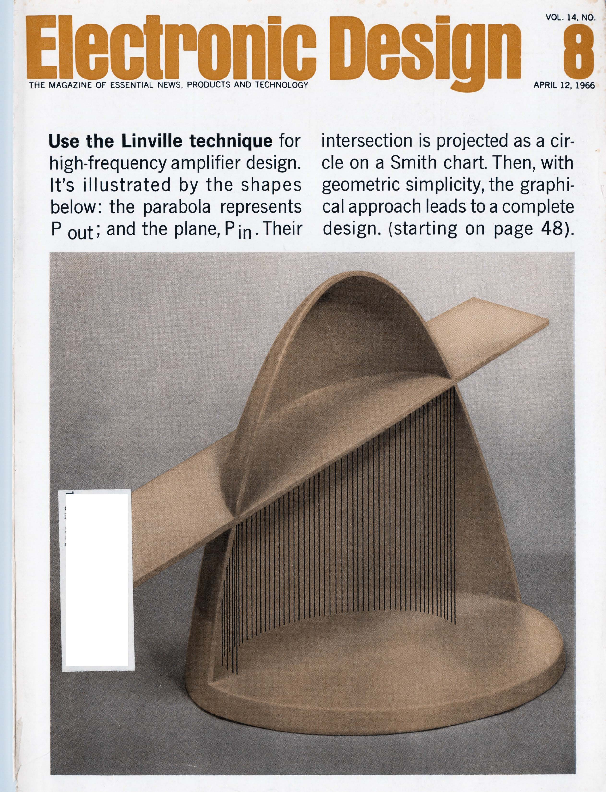
Use the Linville technique for high-frequency amplifier design. It's illustrated by the shapes below: the parabola represents P out; and the plane, Pin. Their

intersection is projected as a circle on a Smith chart. Then, with geometric simplicity, the graphical approach leads to a complete design. (starting on page 48).

(

Jl~eed Gimbal Pickoff Synchros
and Resolvers

The table below shows a small sample of the multispeed pickoff units produced by CPPC for such high reliability programs as Apollo, SIDS, Titan, Pace.
The data listed below are representative of the input/output parameters that we have supplied to meet customer requirements. The accuracies reflect the maximum errors allowed. Clifton units usually are well below these spetified maximums.
The outline dimensions given in the table are applicable to rotor-stator combinations; although, as the photographs on this page show, our multispeed units are usually supplied in housings.
If you have a requirement for a high accuracy , high

reliability multispeed component, contact CPPC Sales Engineering for additional information.
Clifton Precision Products, Division of Litton Industries, Clifton Heights, Pa., Colorado Springs, Colo. 215 622-1000, TWX 215 623-6068.

CLIFTON Multispeed Gimbal Pickoff Synchros and Resolvers

Function
Ix, 8x Resolver Ix, 15x Synchro
Ix , 16x Resolver I6x Resolver
Ix, 32x Resolver Ix , 16x Resolve r
36x Resolver Ix, 64x Resolver
64x Resolver

Input
26v 80026v 400-
28v 80028v 800-
15v 320028v 800-
28v 800 28v 4800-
28v 800-

Primary
Rotor Rotor
Rotor Stator
Rotor Rotor
Stator Rotor
Rotor

Common Input Impedance
85 0 1190 105 ,. 1165
175 r 1600 40 -r 1350
100 + 1300 165 + 1600

Output Imp.. Prim .Shor ted

h

N1

100 . 120

20-,- 115

I 150 - 175 160 - 1130

200 Max -

100 Max 450 . 1800

100 Max 175 -'- 1100

350 Max 100 Max�

TR & Phase Shift

h

N1

.220 - 9 .390 - 21 '

.220 - 24 .390 - 47�

1.00 - 4' -

.179 - 12� 1.00 - 6�

.333 - 3 1.00 - 3.5

.333 - 13� .179 - 12'

Acc ur acy

h

N1

10

I

Dimens i on s

l.D .

D.D.

w.

1-- ~ , - -

1.437 2.687 .500

10"

20" 1.500 3.400 .600

+--

2

20" 1.687 3.687 .675

-

20" 1.687 3.687 .675

10

1 -t--
15" 1.187 3.750 .500

4

20" 1.187 4.000 .610

120 r 1200

-

230 -r 1200

-

.300 - 28'

-

mo 10 +

70 - 145

80 �- 1120 .400 - 2�

.270 - 15'

30

8" 1.400 3.500 .850
I 7" 2.250 4.000 .700

260 I- 1200

-

350 r 1260

-

.179 - 55� -

5" 2.250 4.000 .700

rn CLIFTON ~=~g~b~~
DIVISION OF LITTON INDUSTRIES 1

Speed Inquiry to Advertiser via Collect Night letter ON READER-SERVICE CARD CIRCLE 242

Thousands of these Oscillators are in use today
HIGH OUTPUT � BROAD RANGE � LOW COST
All these oscillators have typical outputs in the order of several hundred milliwatts. All have singledial control and an input jack for a modulating signal. All are available for rack- or bench-mounting. All operate from any of several compact, inexpensive power supplies that range in price from $65 for the basic unregulated supply to $170 for the unit providing regulated de heater and plate voltages. Another power supply, the Type 1263-C Amplitude-Regulating Power Supply ($425), provides I-kHz square-wave modulation and levelled output for any oscillator except the Type 1208-C. For 100% pulse and square-wave modulation, the Type 1264-A Modulating Power Supply ($285) is available for use
with any oscillator except Types 1208-C and 121 1-C.

Type1218-B $595 in U.S.A.

Typical output >300 mW over most of frequency range. Calibration accuracy �1 �lo.

Type 1209-C $330 in U.S.A.

250 to 960MHz

Type 1361-A $315 in U.S.A.
Typical output > 200 mW over most of the range. Calibration accuracy �10/o.

Typical output > 250 mW over most of range. Calibration accuracy �10/o.

180 to 600MHz

Type 1208-C $295 in U.S .A.

65 to 500MHz

Type 1209-CL $330 in U.S.A .
Typical output > 500 mW over most of the frequency range. Calibration accuracy �10/o.

Typical output > 400 mW over most of range. Calibration a~curacy �20/o.

50 to 250MHz

Type 1211-C $375 in U.S.A.

Typical output > 300 mW over entire range , > 1 W from 0.7 to 5 MHz. Calibration accuracy � 20/o.

Type 1215-C $250 in U.S.A .
Typical output > 200 mW over most of range. Calibration accuracy �10/o.
Write for complete information. Also ask about our new series of
"sync-able;' low -frequency, high-performance oscillators.

BOSTON � NEW YORK � CHICAGO � PHILADELPHIA � WASHINGTON , O.C. SYRACUSE � DALLAS � SAN FRANCISCO � LOS ANGELES � ORLANDO CLEVELAND � TORONTO � MONTREAL

BOURNE ENO , ENGLAND

ZURICH , SWITZERLAND

GENERAL RADIO
WEST CONCORD, MASSACHUSETTS

ON READER-SERVICE CARD CIRCLE 212

supply and front panel plug-in. In a large syste , importance of expedient maintainability. REDCOR's total plug-in feature, integrated circuit micro-elements, provides inexpensive spares provisioning and reduces "mean -time-to-repair" to seconds which minimizes troub leshooting costs. Total plug-i n capability also provides proven re liability, optimum performance and prompt delivery.

ANALOG-TO-DIGITAL-TO-ANALOG DATA ACQUISITION SYSTEMS
Engineers: If your f ield is analog/ digital data systems or com ponent design , a career opportunity awaits you at REDCOR. Write to Personnel Director.

m@REDCOR . DCORPORATION

P. 0 . Box 1031 I CANOGA PARK , CALIFORNIA 91304 / PHONE: (213) 348-5892 / TWX: 213-348-2573

Speed Inquiry to Advertiser via Collect Night l ette r

ON READER- SERVICE CARD CIRCLE 2

2

ELECTRONIC DESIGN

Electronic Design"'"''""I"i" "'"'"''"""""'"""'�"�'""''""'"'""'"

NEWS

13

News Report

17

Electroacoustic amplifiers about to leave laboratory

Practical devices operating at several hundred MHz are expected within a year.

A 60-MHz prototype has already been announced.

21

Wire modules fast with sticks and stacks

Two firms introduce unusual methods for wiring modules. Will their growing

use displace the ci rcuit designer?

26

Are you up on power supplies?

28

Gunn effect invades millimeter region

31

Washington Report

36

Letters

43

Editorial: Engineers are too often silent on social issues.

TECHNOLOGY

48

Design high-frequency amplifiers graphically, relating stability, gain , bandwidth

and sensitivity with Linville-Smith charts .

58

Swamp out distortion in wide-range age systems by using a diode bridge variable

attenuator in the feedback loop. Stability and high accuracy also result.

62

Use an IC counter next time! You can build a completely integrated counting

circuit by using sequential majority-logic elements.

68

Speed control system response and cut system cost with potentiometer padding.

Here 's a graphical technique that makes it easy.

72

Need a pedestal-free gate? Use a diode bridge circuit and balance out those

unwanted spurious gating signals.

76

Cut radar hardware needs and costs with a special multi-mode antenna feed

that requires only two hybrids to measure azimuth and elevation.

80

Test system uses telemetry data to check performance of relays in airborne

electronic package. The results are displayed visually on a counter.

84

Ideas for Design

100 NASA Tech Briefs

PRODUCTS

104 Test Equipment: Variable resistor for precision uses

116 Components: Stepless control with a $1 Triac

146 Semiconductors 148 Materials

156 Production 160 Power Equipment

150 Microelectronics 152 Microwaves

161 Systems

Apr il 12, 1966

Departments
166 New Literature 170 Application Notes 172 Design Aids

174 Advertisers ' Index 176 Designer's Datebook

ELECTRONIC D.ESIGN is published bi �week ly by Hayden Publishing Company, In c ., 850 Third Avenue, New York, N . Y., 10022. Jame~ . Mulholland, Jr.. President . Printed at Poo le Bros., In c ., Chicago, Il l. , Control led -circ ul ation postage paid at Ch icago. Ill., and New York, N. Y. Copyright � 1966, H ayden Publishing Company, Inc. 58,997 copies this issue.
3

Bendix announces the
B-5000 � (25 watts at 2.5 amps,) � 10 volts and 100�C
a significant cost breakthrough in silicon power transi�stors.

4

ELECTRONIC DESIGN

�It costs under 40C.*

New manufacturing and packaging techniques make the B-5000 possible. These techniques include new internal device element assembly, along with new-concept plastic molding operations. The result is a simple, low-cost, reliable silicon power transistor with no power compromise, when mounted upon the normal heat sink.
B-5000's low cost opens up whole new application areas for you. Now you can afford to put silicon power to work in many industrial and consumer products. Lighting equipment, TV sets, audio amplifiers, appliance sensing amplifiers and industrial controls, to mention a few. Compare the cost of the Bendix�B-5000 with any other silicon power unit of equal rating. You'll discover significant savings.

B-5000 offers advances in size, weight and thermal resistance. Leads and collector strips are highly conductive silver, offering excellent solderability, strength and ability to withstand flex and pull. Plastic encapsulant offers outstanding insulation resistance, hermeticity, adhesion ability and high temperature characteristics. In no way does B-5000 compromise traditionally accepted reliability practices.
With B-5000 you can tailor mounting techniques to fit your needs exactly. Depending on heat sink, available space and degree of assem bly line mechanization , B-5000 can be mounted in the fashion best suited to yo ur operation. For example, B-5000 is readily adaptable to the newer assembly solder techniques without degradation.

B-5000 lends itself equally well to other commonly used production line techniques.

Electrical specifications

Characteristic
VCEO ICEO ICBO VBE hFE hFE VCE(s)

Limits

Test Conditions

Min. Mar. Unit VvCB VvCE

IC A

18 mA

�TcJ

35 - v

0.2

- 10 mA

25

--
30
-20

1.5 1.2 250
-
1.2

m--vvA

14

14 14 14

0.5 0.5 1.0 1.0 50

150

Absolute maximum ratings
VCE0 =35 volts, IC = 3 amps , 18=1 amp, Tstg =- 65 to 175�C, TJ = - 65 to 150"C.
For complete information about the new Bendix B-5000 silicon power transistor, wri te to us in Holmdel, New Jersey.
*In" vo lume quantities

April 12, 1966

Bendix Semiconductor Division
HOLMDEL, NEW JERSEY

T~nc(~
CORPORATION

ON READER-SERVICE CARD CIRCLE 3
5

Like to see our new T Series modules perform?
Warm~ up your scope, we'll be right over.
Our new T Series integrated circuit logic modules are so fast and flexible that we can hardly blame you if you doubt the
amazing specs: Fan out of 14. Noise rejection up to 1.8v. 18 nanosecond gates. 40 nanosecond flip-flops.
So we've given our men demonstration kits and you can see for yourself.
Each kit contains an assortment of module cards and has its own power supply and timing source. You furnish the problems and the oscilloscope.
Our man may even leave the kit a few days for you to play with. Fun.
Scientific Data Systems
1649 Seventeenth Street, Santa Monica, California U.S. sales offices in New York, Boston, Washington, Philadelphia, Pittsburgh, Huntsville, Orlando, Chicago, Houston, Dallas, Albuquerque, Denver, Seattle, San Francisco, St. Louis, Detroit.

A new miniature sensitive relay from RBM CONTROLS IT WILL BE COPIED BUT NEVER EQUALED

Reason-RSM CONTROLS has more production

ENGINEERING SPECIFICATIONS

and quality control experience and has built more sensitive miniature relays than any other manufacturer in the industry.

CONTACTS
Ratings: 28V DC or 115 V AC l Amp (Non-inductive) Form: SPNO, SPNC, SPOT Type: Cross-Bar

The new miniature Type 64 is an isolated contact relay for maximum sensitive applications

COIL RATINGS
Maximum-1 Watt Minimum-.050 Watt Resistance-10,000 Ohms Max.

where reliability, rugged construction and low cost are of major importance. This low level cir-

TERMINALS Contact: To Mount To Printed Circuit Board

cuit switching relay is designed for compact areas and may be stack assembled in close proximity to each other. A protective nylon cover eliminates physical contaminance or mishandling. A variety

APPROXIMATE DIMENSIONS

(Overall Including Brackets and Mountings)

Printed Circuit L 1-3/ 16" x W 3/ 4" x H 1-3/ 8"

Bottom

L 1-3/ 16" x W 3/ 4" x H 1-9/ 16"

Top

L 1-11/ 16" x W 3/ 4" x H 1-15/ 32"

Parallelogram L 1-3/ 16" x W 1-7/ 16" x H 1-15/ 32"

of mounting brackets are available making this

MOUNTINGS

relay the most versatile in the industry.

Printed Circuit Board Bottom

8
lijikll;lil(j
- � ,..... ��-

Serv1�ng

M �
.a1or

Markets

Si.nce

1921

Top-Parallelogram Replacement Top Mounting Also Available

RBM CONTROLS
Division Essex Wire Corporation Logansport, Indiana

STANDARD CONTROLS ARE AVAILABLE FROM YOUR ELECTRONIC PARTS DISTRIBUTORS

Speed Inquiry to Advertiser via Collect Night Letter

ON READER-SERVICE CARD CIRCLE 4

~ ON READER-SERVICE CARD CIRCLE 21 3

7

No one has a larger line of disc.memories.

See the largest line of disc memories available at the Spring Joint Computer Conference, Booth 913-916 Whether your information storage requirements are small or require data stored in millions of bits , Librascope Group of General Precision, Inc., has a disc memory system for every application . These systems have a proven history of reliable performance in com� puting systems designed for military, business, engineering, and educational applications. LIBRAFILE mass memories: Large� capacity, high -speed , random -access information storage systems. Two disc sizes available. 48" discs capable of storing up to 400 million bits. 38" discs with a capacity of 200 million bits. LIBRAFILE mass memory information retrieval is either fixed -address search or search-by-record content. Access time less than 20 ms. Data transfer rates in the megacycles.
8

Militarized disc-memory systems: Highspeed , random -access , information storage systems . Consists of disc memory for data storage and an electronic subsystem that provides com plete interface, control , and read /write electronics. These systems can be used as a data base for shelter, van, or shipboard applications. Storage capacity of 25 million bits on 24" discs. Customized capacity up to 80 million bits. L-400 magnetic-disc memory systems: Provide data storage and transfer in computer systems, peripheral equipment, and other systems where rapidaccess memory is a requirement. 24" disc storage capacity up to 36 million bits. Airborne disc file: Small , compact file designed for airborne (MI L-E-5400 class 2) applications, as ~ell as for shipboard and mobile field operations. 6V4 " disc with capacity of 1 million bits. Custom ized airborne memories available with
ON READER-SERVICE CARD CIRCLE 55

capacity up to 50 million bits. L-300 disc memory: For use in computer systems and peripheral equipment as main storage, buffer storage, or as a supplemental memory. 10" disc with a capacity of 275,000 bits. For complete details, write for our tech nical bulletins. Engineers: For career openings , call or send resume in confidence to B. Larson , General Precision , Inc. , Librascope Group, 808 Western Avenue, Glendale, California 91201. An equal opportunity employer. A Plans-for-Progress Company.
LIBRASCOPE GROUP
DD D 808 Western Avenue O OD O DD Glendale, Calif. 91201 O 0 O

When you look at electronic components are you seeing only half the picture?

We're the last people to argue with component purchasers who put performance, price and delivery first - meeting these three basic requirements is what keeps us in business. But most engineers are also on the lookout for something more, and many of them find it at Mullard. Take research and development for instance. Out of Mullard R&D have come outstanding devices such as the travelling wave tubes for the New York-San Francisco and MontrealVancouver microwave links. Production resources? Mullard

plants are among the most efficient anywhere, with a reputation for the production of tight-tolerance devices to proved standards of reliability. As for circuit know-how, Mullard has the best equipped applications laboratories in Britain. And when it comes to technical services, you will find that Mullard provides the kind of comprehensive performance specs, survey documents and application reports that are just that much more useful. If you want to get the whole picture, why not ask us to help you with some of your component problems?
ON READER-SERVICE CARD CIRCLE 214

DIODES � TRANSISTORS � PHOTO-DEVICES AND RADIATION DETECTORS � RECTIFIER DIODES AND STACKS � THYRISTORS AND STACKS � INTEGRATED CIRCUITS � CATHODE RAY TUBES � RECEIVING TUBES � ELECTRON OPTICAL DEVICES � PHOTOSENSITIVE DEVICES � COLD CATHODE DEVICES � POWER DEVICES � TRANSMITTING TUBES � MICROWAVE DEVICES � CAPACITORS � FERRITE MATERIALS AND ASSEMBLIES � COMPUTER COMPONENTS AND ASSEMBLIES� MAGNETIC MATERIALS� SPECIAL PURPOSE MAGNETS� VACUUM DEVICES � WOUND COMPONENTS.

Mullard
where the product is only part of the deal
MULLARD LIMITED � TORRINGTON PLACE � LONDON WCI � ENGLAND

UNICIRCUIT� RTL INTEGRATED CIRCUITS
TQ.5 CASE
Types US�0708 through US�0721 . .. Fully inter� changeable mW digital building blocks featur� ing power consumption of 4 mW/node and pro� pagation delay of 40 nanoseconds.
ON READER-SERVICE CARD CIRCLE 821
UNICIRCUIT� CUSTOM HYBRID CIRCUITS
Combine monolithic silicon circuits with Ni�Cr alloy resistors. Close resistance tolerances, low tempera �
tu re coefficient, � 2% resistor
matching.
ON READER-SERVICE CARD CIRCLE 824
DUET* HIGH-VOLTAGE
�; ; ; , .err. DUAL-EMITTER TRANSISTORS I I w�.:u. 1~:=...c. C.OHKlOll
New Type 3N 123 low.cost transistor with 25�volt rating now available.
� � �
Sprague makes more dual�emitter chopper transistors than any other source.
*T11d1muk
ON READER-SERVICE CARD CIRCLE 827
10

DIFFERENTIAL AMPLIFIER TRANSISTOR PAIRS

~

TO �I S CASE

T0 � 5 CASE

FLAT PACK

NPN or PNP � Matched characteristics.
h FE= 10�20o/o. ~VeE = 5.20 mV.
~V8 (/Temp = 5�20 �V/�C.

ON READER-SERVICE CARD CIRCLE 822

LOW-COST HERMETICALLY-

SEALED PLANAR TRANSISTORS

~~ C !>

TN55�TN58 Low Level Amplifiers

~ ~ ~~

TN5HN64 General Purpose Switch/Amplifiers

TN79�TN80 Chopper Transistors

TN81 Power Amplifier

Tc�AJ~

TN23HN238 Gold Doped Core Drivers

b~s5E

ON READER-SERVICE CARD CIRCLE 825

TWIN DUET* DUAL �EMITTER TRANSISTORS IN FLAT PACKS

UNICIRCUIT� RCTL INTEGRATED CIRCUITS
1 1i�-l.~.. ,..~.,.., .'� ~-~'11 �
(8x actual size)
Sprague Series US�OlOO ... a complete line of monolithic digital building blocks featuring low power consumption (2 mW typ.)
ON READER-SERVICE CARD CIRCLE 820

MULTIPLE TRANSISTORS
(NPN-PNP PAIRS/QUADS)
!/#~Jiff

AMPLIFIERS SWITCHES

CHOPPERS

Pairs
2 NPN 2 PNP 1 NPN-1 PNP

Quads
4 NPN 4 PNP 2 NPN-2 PNP

ON READER-SERVICE CARD CIRCLE 823

SILICON ALLOY REPLACEMENT TRANSISTORS

FULL PLANAR RELIABILITY

2N327 A 2N328A 2N329A

2N945 2N946 2N1025

2N1026 2N1469 2N1917

Sprague makes 82 standard high� emitter�voltage full planar silicon alloy replacement types.

ON READER-SERVICE CARD CIRCLE 826

For complete technical data on any of these products, write to Technical Liter� ature Service, Sprague Electric Company, 347 Marshall Street, North Adams, Massachusetts 01248.

Sprague leads again with two dual� emitter chopper transistors in one flat.pack case, with tight VorF matching of both devices.
*Trad1m11k
ON READER-SERVICE CARD CIRCLE 828

SPRAGUE�
THE MARK OF RELIABILITY
�Spr11ue' 1nd �@� ere reeistered tr1dem1rks of the Spr11ue Electric Co .
ELECTRONIC DESIGN

ED News
Electroacoustic amplifiers leaving laboratory PAGE 17 Giant lasers have high light intensity PAGE 20 New packaging speeds wiring of modules PAGE 21 Gunn effect invades millimeter region PAGE 2s

Gunn power . . . 28

Putting rubies to work . . . 20

Sticks and stacks . .. 21

April 12, 1966

11

leaders in GHz counting

\Tes, it's tl1a1t si11111le ft� 111ea1s111�e 111ic1�tt\\'ll\'e �
f 1�e�111e11cies tli1�ectl\T

Just connect the input signal and read the answer! Systron-Donner's new frequency measuring system is completely automatic. No calculations, no manipulations of any kind. This great new tool for the lab and production testing will prove to be as necessary as a digital voltmeter.
S-D can deliver this ~utomatic system now for measurements between 3.95

and 8.2 GHz. Soon we ' ll offer coverage over the rest of the microwave spectrum . The system shown here illustrates the basic concept-a combination of the S-D 50 Mc Model l 037 Counter and the S-D Model 1254 Automatic Computing Transfer Oscillator. Other plug -ins will cover L, S and X bands. FOR MAXIMUM STABILITY - Systron Donner exclusively offers a high stabil-

ity oscillator with on ag ing rate of 1 port in 70� per 24 hours . That's a three fold increase in stabilit y over the best previous osci Ila tors! Prices : Model l 037 Counter, $2,550.
Model 1254 ACTO Plug -in, $1,950. To
learn more about automatic GHz counting, please write to us in Concord or contact your nearest S-D sales engineer (listed in EEM).

SYS TRON

DONNER

CORPORATION

888 Galindo Street � Concord, California

Speed Inquiry to Advertiser via Collect Night Letter

ON READER-SERVICE CARD CIRCLE 6

12

ELECTRONIC DESIGN

Time is ripe for commercial diversification
If a defense-oriented firm is considering diversifying into the commercial market, now is the time to do it. So says the Denver Research Institute of the University of Denver in a recent study entitled "Defense Industry Diversification."
The researchers' conclusion followed an analysis of recent diversification programs by U.S. defense manufacturers. They found that the prospects for successful diversification appeared best when defense spending and the demand for defense hardware were expected to increase. The study found that a substantial time lag occurred between the start of diversification programs and first profits. Therefore, a program should be begun in time to make its contributions to corporate profits when these contributions are most neededwhen defense demand is cut back.
In discussing the problems of diversification, John S. Gilmore, who led the study, pointed up the crucial role of management. He said: "Responsibility for diversification rests with the management of defense firms, and the commitment and participation of top management is the key item in any successful diversification program. This type of commitment is often difficult to achieve due to a number of diverse factors, including a discouraging history of failure in commercial diversification efforts, strong doubts that the defense customer wants diversification, and the seeming lack of stockholder interest in diversification efforts."
No hiding from new air recon system
The use of additive color techniques has led to an aerial reconnaissance system that makes interpretation much surer and gives more valuable intelligence data.
The new system facilitates detection by making objects which might be indistinguishable in conventional color or black-and-white infrared photography stand out from their background.
Developed by Fairchild Space and Defense Systems, it uses a single panoramic camera equipped with four rotating lenses. The lenses record images of the same target, through
April 12, 1966

News
Report
blue, green, red and near-infrared filtern, side-by-side on a strip of infrared film. The resultant black-and-white negatives are then converted to positive transparencies.
To interpret the photographs, the transparencies are placed in a special four-lens viewer and superimposed on a screen in various combinations through a selection of filters. Varying the brightness, saturation and hue of each image, either separately or in combination, brings out maximum contrast between targets and their surroundings.
With conventional photo-reconnaissance a military tank standing in deep shadow and covered with an infrared-absorbing camouflage net was invisible on regular color, panchromatic or infrared film. But with the new system, all shadows appear achromatic (gray or black), while the tank is clearly visible in vivid color.
System sought to avert air collisions
Development of an airborne system to prevent mid-air collisions of commercial aircraft is nearing success, according to the Operations Executive Committee of the Air Transport Association (ATA).
This optimism stems from progress made 0n a collision-avoictance system under development by McDonnell Aircraft. In its present form the system is not suitable for airline use, especially as it must be carried in an externally mounted pod. But the airlines and McDonell have been examining ways to make it suitable for more than three years. These investigations are believed to be so close to a payoff that the ATA has directed its Air Traffic Control Committee to take all possible steps to further McDonnell's efforts to adapt the system for early in-flight evaluation by airlines.
The system is of the cooperative type: both the "intruding" aircraft and the "protected" aircraft must carry cooperating equipment. In a non-cooperative system only the protected aircraft need carry collisionavoi dance equipment. Although the non-cooperative type is more desirable, it is universally agreed that a practical system of this sort is still far beyond current capabilities. McDonnell's system uses the time-frequency
13

News
RIDOrl CONTINUED
technique, which recent research has shown to be the most promising for cooperative collision-avoidance systems. In a time-frequency system each aircraft is assigned its individual time to transmit on a shared frequency.
Successful operation of such a system requires both frequency and time to be measured with great precision.
Teaching aids offer growth opportunities
Increasing student enrollment, continuing shortage of teachers and expanding Federal and state expenditures for education-put these three together and they spell "growth market" for audio-visual and other electronic educational aids.
Commenting on this, Robert L. Rice, president of Graflex, Inc., told the spring conference of the Electronic Industries Association that education is the fastest growing segment of the economy. Combined Federal and local spending on education now reaches $23-25 billion annually, second only tQ defense. According to Rice, this market's greatest potential for the electronic industry is in basic audio-visual electronic aids.� not in sophisticated items such as computers. He said that companies should concentrate 011 building simple, durable equipment for
untrained teachers to operate. In view of many
teachers' fear of electronic aids, he advised against over-emphasis on the development of new or revolutionary equipment.
Full-scale experiment uses ..supermagnet"
A milestone in high-energy physics has been reached with the first use of a supermagnet in a full-scale experiment. Built at the Atomic Energy Commission's Argonne National Laboratory, the supermagnet is so called because it uses the principle of superconductivity to create a strong magnetic field.
Compared with the electromagnets used today in high-energy physics experiments, the supermagnet is relatively small. It has an outer diameter of 24 inches and an inner diameter of 11 inches. Despite its size it can sustain a magnetic field that is stronger than the fields of almost all larger conventional magnets. Furthermore, it does so at a great savings in power. Only a small laboratory-type power supply is required to energize the supermagnet,
14

which then functions indefinitely without further electrical power as long as it is kept cold. Comparable electromagnets, on the other hand, require millions of watts of electrical power.
The supermagnet was used at Argonne in a bubble-chamber experiment to track energetically-charged particles. Liquid helium is used both in the bubble chamber to track the particles and to cool the supermagnet.
Cooperative researchers sought by NBS
The National Bureau of Standards has announced new areas of research open in i:ts cooperative program of joint Governmentindustry research. Under the program, scien'tists and engineers from industry are invited to work ,temporarily at NBS laboratories on projects of value to their companies as well as to the scientific and technical community at large.
The new areas include investigation of the use of lasers for length measurement, computer languages, data-processing systems and studies of cryogenic fluids in flow. Complete details on the program are available from the Office of Industrial Services, National Bureau pf Standards, Washington, D.C.
Acquisition of Computer Control Co., Inc., by Honeywell, Inc., has been agreed upon
subject to final approval by the boards of
directors of both companies. According to Honeywell, the operations of 3C will complement the operations of the company's electronic data-processing division. The present 3C organization will operate as a separate unit of Honeywell under its present management and personnel.
NASA has named the crew for the first manned Apollo earth-orbital mission. Prime crew are Lt. Col. Virgil I. "Gus" Grissom (USAF), Lt. Col. Edward H. White, II, (USAF), and Lt. Roger B. Chaffee (USN). Back-up crew are Lt. Col. James A. McDivitt (USAF), Major David R. Scott (USAF), and Mr. Russell L. Schweickart, a civilian. The first manned Apollo mission is tentatively scheduled for the first quarter of 1967.
Formation of a joint study group to investigate the potential of electronic systems in the broad field of education has been announced by The Reader's Digest Association, Inc., and Sylvania Electric Products, Inc. According to the two companies the study group will seek the best methods of integrating electronic capabilities and educational materials into practical systems that will help meet the rapidly expanding needs of education.
ON READER-SERVICE CARD CIRCLE 225 ...

Portable Five�Dial Potentiometer: $535

Volt Box: $135

Pico�ammeter: $485

We packed $4,000 worth of measuring capability into this new portable package.

For $750 it does the work of 9 devices.

We call this versatile instrument our your car. When you need it, you need Portametric PVB. That stands for it bad. Then yo u're glad you didn't

Po.tentiometric Voltmeter :Bridge.

buy just one or two of those black

Actually, it's more than a potentio� metric voltmeter and more than a bridge. But how many words can we reasonably put in an instrument

boxes above when you could have had the works at our price.
If you know ESI, you know we put a lot more emphasis on performance

name?

than price. We only mention price

At the moment, you may not feel here so you will appreciate the tech-

you need all the capabilities, or the nical advances represented by the

degree of accuracy the PVB can de- specifications on the right-and send

liver. But extra measurin g power is for details. ES/, 13900 NW Science

something like reserve horsepower in Park Drive, Portland,Oregon (97229).

[elsli Jov Electro Scientific Industries, Inc.

Function

Ranges

Full Scale

Minimum Step

Voltmeter

5

0.051110 to 511.10 volts

1 microvolt

Ammeter

8

0.51110 �a to 5.1110 amperes

10 picoamperes

Resistance Bridge 10
(4 terminal, guard ed )

0.51110 ohms to 10 microhms 511.10 megohms

Comparison Bridge
(4 terminal, guarded )
Ratiometer
(D irect reading )

To 5.1110 times reference standard
3

1.0000

o o

to to

1.00000 0.051110

Oto 0.0051110

0.01 %
1 part in 10�5 1 part in 10�6 1 part in 10�7

Null detector: Sensitiv ity- 5 microvolts; Input impedance-approximately
megohm ; AC rejection 60 cps and up ; 80 db, guarded, battery operated. Accuracy: � 0.02% of read ing or 1 switch step on virtually all ranges and functions. Comes in portable case; battery operated ; 2,000 hour battery life.

40.00

u 39.99
'O
~

w

(�.!:)
I-' 39.98
> 0

I-

:a:>..

I-

::> 0

39.97

39 .96

8.00

8.QJ

8.02

8.03

8.04

8.05

OUTPUT CURRENT (Ade)

-,

I
I
I I
I
I I
I
I
I

8.06

8,07

Automatic crossover between constant voltage and constant current modes

Power Supply Specs

That Set The Standard.

The Sorensen QRC series-wide range, transistorized powe. supplies- provide constant voltage/ constant current regulation so sharp the units operate without ever leaving the specified regulation band. Voltage regulation is + .005 % for line and load combined. The QRC's are provided with front panel dial set adjustment of voltage and current limits, as well as voltage/ current mode indicator lights. Other design features include: Low ripple .. . 1 mV rms � No turn-on / turn-off overshoots � Re-

mote sensing and programming � Series/ parallel operation � Input voltage 105-125 or 201-239 Vac, 50-400 c/ s � Easily replaceable plug-in control boards � High efficiency and compact packaging. All Sorensen power supplies conform to proposed NEMA standards. For QRC details, or other standard / custom power suppl ies, AC line regulators or frequency changers, contact your local Sorensen rep, or write: Sorensen, A Unit of Raytheon Company, South Norwalk, Connecticut 06856.

MODEL NUMBER

OUTPUT VOLTAGE
RANGE (Vdc)

CURRENT OUTPUT RANGE
(Ade)

ELECTRICAL & MECHANICAL SPECIFICATIONS - - - - - - - - - - - - - - - - - - - - ,

VOLTAGE REGULATION (LINE & LOAD COMBINED)

RIPPLE VOLTAGE
(rms)

CURRENT REGULATION

RIPPLE CURRENT
(rms)

RACK HEIGHT (INCHES)

PRICE

QRC20 -08

0-20

QRC20 -15

0-20

QRC20-30

0-20

QRC40 -4

0-40

QRC40 -8

0-40

QRC40 -15

0-40

QRC40 -30

0-40

I Half rack

0-8 0-15 0 -30 0-4
0-8 0-15 0-30

� .005% ar � 1 mv � .005% ar � 1 mv � .005% or � 1 mv � .005% or � 1 mv � .005% or� 1 mv � .005% or� 1 mv � .005% or� 1 mv

1 mv 1 mv 1 mv 1 mv 1 mv 1 mv 1 mv

� .05% or� 4 ma � .05% or� 8 ma � .05% or � 16 ma � .05% or� 2 ma

2 ma 4 mo 8 ma 1 ma

3Y2

$410 .00

SY..

525 .00

7

700 .00

sv.. t

315.00

� .05% ar � 4 ma � .05% or� 8 ma � .05% or� 16 ma

2 ma 4 ma 8 mo

3Y2

450 .00

sy.

575.00

7

775.00

Sorensen represented in California by Ward�Davis Assoc ., 770 S. Arroyo Parkway, Pasadena, Phone
213-684-2840; 1020 Corporation Way, Palo Alto, Phone 415-968-7116 ; 3492 Pickett Street, San Diego. Phone 714-297-4619.

A UNIT OF RAYTHEON CO MPANY

NEWS

Electroacoustic amplifiers about to leave� lab?

Motorola develops 60-MHz prototype with 60-dB gain. Higher frequency devices expected soon.

Ralph Dobriner West Coast Editor
Bulk-effect electroacoustic amplifiers may soon move out of the research laboratory and become available for practical application.
This is the view of spokesmen at Motorola's Military Electronics Div., in Phoenix, Ariz., who informed ELECTRONIC DESIGN about development of a prototype 60-MHz, cw-operated electroacoustic amplifier with a 60-dB net gain.
N. A. Sakiotis, head of the division's applied microwave research section, said : "Within a year we hope to have a practical 200- to 500-MHz amplifier working within an equipment environment."
Transducer loss problem
The phenomenon of amplification of ultrasonic waves through their interaction with moving charge carriers in piezoelectric semiconductors has been known for several years. But it has so far been difficult to realize net gain from an amplifier structure because of transducer losses. In addition, said Sakiotis, the first experimental net gain amplifier, which he helped develop in 1963,

had to be pulsed to prevent excessive crystal temperature rise.
"Since then," the scientist declared, "not only have we reduced transducer losses, but design, fabrication and heat sinking techniques have been developed so that cw operation at room temperature is now possible."
The electroacoustic amplifier, which consists of a single, homogenous cadmium sulfide (CAS ) crystal 6-mm long by 2-mm square, is being developed by Motorola, partially under Air Force sponsorship.
The company said it plans eventually to build similar amplifiers at microwave frequencies, perhaps as high as 1 or 2 GHz, for use in space and military hardware. SixtyMHz versions have already been delivered to the Air Force and Motorola is presently delivering a 200MHz device.
Sakiotis observed that the 60MHz amplifier "provides performance which would conventionally require several stages of transistor amplification consisting of at least 50 circuit elements." By comparison, the electroacoustic amplifier can provide the same am-

PIEZOELECTRIC TRANSDUCERS (THIN-FILM CdS)

INPUT~ c_'_V _.......L~~---=.---+---r"--......,. ~OUTPUT

EVAPORATED METAL OHMIC CONTACT

DC DRIFT VOLTAGE

The basic amplifier consists of an active crystal, such as cadmium sele.nide, with piezoelectric transducers (high-resistivity CdS) at . ea:h end. T~e rnp~t transducer converts the RF input to an acoustic wave which increases. 1.n amplitude drawing energy from the de drift source. At the output the amplified wave is converted back to an electrical signal.

plification with three circuit elements at most.
Thus, he said, the amplifier is eventually expected to be to microwave RF and IF amplifiers what monolithic integrated circuits have been to digital circuitry.
It works on the lines of a TWT
In principle (see illustration), the basic amplifier consists of the active crystal-in this case CdS, though gallium arsenide and cadmium selenide have been usedwith piezoelectric transducers at each end. The input transducer converts the applied electrical signal into an acoustic wave. As the acoustic wave progresses through the crystal it increases in amplitude, drawing energy from the de drift source, in a manner analogous to a signal being amplified in a traveling-wave tube. At the output the amplified wave is converted back to an electrical signal.
In the 60-MHz Motorola configuration, the 6-mm-long CdS crystal is oriented with its hexagonal axis normal to the direction of acoustic wave propagation.
Thin-film transducers, consisting of high resistivity cadmium sulfide, are deposited on metal contacts which are evaporated on opposite ends of the crystal to provide ohmic contact.
The de bias voltage is isolated from the RF signal by coupling the signal through a transformer to the transducer at the high voltage side. Appropriate electromechanical matching is accom-. plished by using inductors which give essentially resistive input and� output impedance of about 50 ohms. The total loss through the amplifier with a crystal resistivity of 106 ohm-cm is 20 dB at 60 MHz.
Total gain of 60 dB is achieved with RF input-signal levels of up to 10 mV. For hi gher signal-level inputs, the output is s lightly greater than one volt. A de drift voltage of 600 volts is maintained across the crystal. The bandwidth of the amplifier measured at the half-power points is about 5 %. To-

~ ON READER-SERVICE CARD CIRCLE 200

17

NEWS
(electroacoustic, continu ed )
ta! power consumption in the amplifier is less than one watt.
8- to 14-dB noise figure
According to Sakiotis, the amplifier's noise figure, which is essentially controlled by the input transducer loss, is now between 8 and 14 dB at 60 MHz. There is no reason why this figure could not be reduced to 3 or 4 dB with the lower-loss transducers, presently under development, he said.
"This would make the device competitive with transistor and even integrated circuit amplifiers, not only in terms of noise and compactness," the scientist observed," but also because they're a lot easier to make."
Motorola is presently working on hybrid IF amplifiers using electroacoustic devices in combination with transistors for use at the lower frequencies. The company, however, expects electroacoustic amplifiers to become really competitive with conventional devices at frequencies above 500 MHz.
One big advantage of electroacoustic devices is that frequency selectivity is inherent, being controlled by the resistivity level of the crystal and the design of the

transducers. Also, gain is a direct function of crystal length and frequency.
At a particular frequency, doubling the crystal length will double the gain within certain limits. Gain also increases with frequency, whereas in transistors, gain goes down as the frequency rises.
An electroacoustic amplifier is, furthermore, bilateral and particularly suited for transceiver applications, It could function as a small-signal RF amplifier for reception, and by reversing the drift voltage, as a power RF amplifier. As a power amplifier, the 60-Mc "Motorola device produces about 500 mW for transmission.
Other companies also at work
Organizations such as the Stanford Research Labs, Bell Telephone Laboratories, Sperry Rand, General Electric, Westinghouse and IBM are also conducting research into electroacoustic devices. Most of the work is still primarily of an R&D nature with little practical hardware development.
Opinions differ among researchers in this field not only on the design and fabri cation of the amplifiers, but also on their ultimate use.
Don White, scientist at Bell Telephone's Murray Hill Labs, declared: "We've been working on

Prototype electroacoustic amplifier produces 60 dB gain at 60 MHz and meas� ures one inch long by one-half inch square. Motorola plans to eventually build similar amplifiers at frequencies as high as 1 to 2 GHz for use in space and military hardware.
18

these devices for a long time and we have more or less come to the conclusion that we would have a hard time selling the electroacoustic amplifier-particularly at the low frequencies where transistors would do a better job."
White said the Labs were looking into possible uses of the amplifier at very high frequencies. They have developed a workable device but "it's still essentially a laboratory curiosity," he observed.
The real question, he said, is whether the amplifier will have anything to offer that cannot be done better in other ways. As an example. White noted that the use of such amplifiers in delay lines was limited because of reflection problems and because the signals can equally well be amplified electrically.
Another scientist, at BTL's Allentown laboratories, agreed that in terms of gain Motorola's amplifier was significant.
He said that the consensus among researchers in the electroacoustic field was that the noise figure, of perhaps 8 dB even in the hundreds of MHz range, is one of the basic limitations of the device. "Although it's not so bad that it can't be lived with, it's still not as good as other amplifiers."
The BTL scientist foresaw its widest application � as a long-delay device at microwave frequencies where it would be used in some sort of composite ultrasonic system to counteract losses in other parts of the system.
Today's ultrasonic delay lines, he said, are useful primarily below 100 MHz, and in that range the loss is not so high that it cannot be made up with standard amplifiers external to the ultrasonic delay line.
Other scientists are working not only on amplifiers, but also on a variety of electroacoustic devices using the bulk effect in semiconductors.
Stanford Research Laboratories is investigating the properties of low-loss thin-film transducers. Herbert Carleton, at Sperry Rand'~ Research Center, Sudbury, Mass., is close to announcing development of an operational electro-optical modulator which will generate acoustic longitudinal waves in a suitable optical material with a moderate amount of RF power. � �
ELECTRONIC DESIGN

Here are 50 applications, in alphabetical order, for Fairchild Linear Monolithic Circuits:
(If we left out your favorite, let us know. We'll include it next time.)

1. A to D converter 2. A. C. amplifier 3 . Astable (free�running)
multivibrator (20V output) 4. Averaging amplifier 5. Bi�stable (flip-flop)
multivibrator (20V output) 6. Bridge amplifier 7. Buffer amplifier 8 . Current source amplifier 9. Chopper stabilized amplifier 10. Clipping amplifier 11. D. C. amplifier 12. Deflection coil amplifier 13. Difference amplifier 14. Differential amplifier 15. Differentiator 16. Digital clock 17 . Gain control amplifier

18. Go/No -go detector 19. Hysteresis comparator 20. Integrator (D .C. or A. C.) 21. Isolation amplifier 22. Lag amplifier 23 . Lead amplifier 24. Level shifting amplifier
(clamping circuit) 25. Logarithmic amplifier 26. Meter amplifier 27 . Oscillators (sine wave and
square wave) 28 . One shot (high speed , precision) 29 . Peak detector 30 . Phase discriminator 31. Preamplifier 32 . Pulse height detector 33. Rectifier 34. Sample and hold amplifier

35. Scaling amplifier 36 . Sense amplifier (20 mil cores) 37. Schmitt trigger 38. Summing amplifier (subtractor
amplifier) 39. Sweep generator (wave form
amplifier) 40. Servo amplifier 41. Time delay amplifier 42 . Unity gain amplifier 43 . Video amplifier 44. Voltage comparator 45 . Voltage controlled oscillator 46. Voltage detector 47. Voltage follower 48. Voltage regulator 49 . Wave form generator 50. Window detector

Here are 4 Fairchild IC's, in numerical order, for use in the above applications:

v..,

�A702C - Differential Amplifier

Compensated Bandwidth 30MHz

Input Offset Voltage

2mV

Input Resistance

20Kfl

V out

STROBE

�A711C- Dual Comparator

Strobe Release Time Input Offset Voltage Input Voltage Range

12nsec
2mV � 5V

For complete product information

Vout

and pricing, contact Fairchild

Distributors, or write us.

�A709C- Operational Amplifier

Open Loop Voltage Gain Output Voltage Swing Input Resistance lnput'()ffset Voltage

4 5 ,0 0 0 � 14V 250KO 2mV

�A710C - Voltage Comparator

Resolution Response Time
(5mV Overdrive) Input Voltage Range

2mV 40nsec
� 5V

FAIRC::HILCl
SEMICONDUCTOR

FAIRCHILD SEM ICONDUCTOR / A D ivisio n of Fairchild Camera and I nstrument Co rpora tion � 313 Fairchild Drive. M o untain View, California (415 ) 962 -50 11 � �TWX : 910 -3 79 -64 35

ON READER-SERVICE CARD CIRCLE 8

April 12, 1966

19

New from Spraguel
\
)

MET ANET�
TRUE METAL-FILM PRECISION RESISTOR
NETWORKS
Save Space, Time, and Money

� High packaging density-4 to 8 times that of individual components.
� Fewer components to stock, handle, inspect, install. Entire module can be hand-inserted faster than one axial-lead component.
� Permit substantial savings over equipment assembled with individual components.
� Epoxy terminal board keeps pin terminals free of resin coating, unlike conventional dipped components, and provides uniform lead spacing.
� Stand-off bosses permit effi�

cient flux removal after solder� ing. Also prevent dirt and moisture traps around leads.
� Extremely stable and reliable. Meet performance requirements of MIL-R- 10509E. Resistance tolerances to + 1 % .
� Ceramic capacitors can be incorporated for further savings and size advantages over individual components.
� � �
For complete information write to Integrated Circuit Application Engineering Department, Sprague Electric Company, 347 Marshall Street, North Adams, Mass. 01248

NEWS
Giant pulse lasers emit intense beams
Two companies have independently developed giant, super-bright lasers. Each will produce many pulses of more than one billion watts peak power. This power is controlled by new approaches to Q switching.
One laser, developed by Westinghouse under special contract with the French government, uses two eight-inch ruby rods with Brewster ends. The oscillator ruby feeds 250 MW of peak power to the amplifier ruby in a 20-ns pulse. The amplifier rod, 7/8 inches in diameter, then releases its billion watts within 20 ns. Westinghouse guarantees the laser for a minimum of 100 shots at one GW, with beam divergence less than 1 milliradian.
The laser is air-cooled and can be shot once in ten minutes. Q switching, which keeps the rod from lasing until full power is built up, is effected with a saturable filter made of vanadium phthalocyanine in nitrobenzene.
The other laser, made b� Korad, a subsidiary of Union Carbide, in Sapta Monica, Calif., also uses two rubies of unlike dimensions. The Korad laser's beam diverges less than two milliradians, but the company claims its rubies will sustain between 400 and 500 shots at maximum output. � �

SPRAGUE COMPONENTS

RESISTORS CAPACITORS TRANSISTORS INTEGRATED CIRCUITS THIN-FILM MICROCIRCUITS INTERFERENCE FILTERS

PACKAGED COMPONENT ASSEMBLIES FUNCTIONAL DIGITAL CIRCUITS MAGNETIC COMPONENTS PULSE TRANSFORMERS CERAMIC-BASE PRINTED NETWORKS PULSE-FORMING NETWORKS

SPRAGUE�
THE MARK OF REUABILITY

'Spraaue' and '(lj are registered trademarks of the Sprague EJectrlt Co .

ON READER-SERVICE CARD CIRCLE 9
20

I
Billion watt lasers made by Westinghouse (above) and Korad (below).
ELECTRONIC DESIGN

Sticks and stacks speed wiring of modules

New IC packaging techniques are part of a growing trend that may change the circuit designer's future

Roger Kenneth Field News Editor
Notable advances in the packaging of integrated circuits have been achieved by two manufacturers. One company has developed a stick that holds the integrated circuits in flat packs. Another stacks the flat packs in tiny ceramic shells, one on top of another. Both methods lend themselves to automatic wiring techniques.
These developments are typical of the rapid changes taking place in a burgeoning module industry. Some observers have speculated that the industrial and commercial use of modules may displace the circuit designer. Others are more optimistic: res and modules will free the designer for more creative work, they say.
The new stick modules, called MicroSystem, allow the engineer to design his circuit with a few strokes

of the pencil. He merely indicates which leads of the flat pack are to be interconnected. Within two weeks the finished prototype is in his hands. The modules, now on the market, are manufacturered by the Engineered Electronics Co. of Santa Ana, Calif. Design charges range around $85 a module.
The other new module, called Norpac, comprises ceramic layers, each of which contains a flat pack. This configuration is said to withstand temperatures up to 200 � C and vibrations as great as 250 Gs. All connections are external, and conductors can even transverse the module. The conductors are pushed through holes in the ceramic and interconnected by an evaporated-metalization process. Manufactured by the Norden Div. of United Aircraft, in Norwalk, Conn., the modules will go on sale later this year.
These are true modules. Other

products on the market that are called modules often are not. The term has been misused in advertising to connote "modern," such that everything from a switch to a tape deck has been dubbed "module." Module makers use the term strictly for complete circuits, composed of more than a single component and arranged either in a three-dimensional configuration (usually encapsulated in epoxy) or on a printedcircuit card with a plug-in connector.
The two latest module lines are important because their automaticwiring potential makes possible large production runs.
The MicroSystem can accommodate ten or even more flat packs. In place, the ICs look like spiders on a stick. Any lead can be connected to any other by the mylar-insulated conductors inside the stick. Thus, John Fahy, Engineered Electronics Co.'s district manager, reports that the firm took only five days to make an interface between a computer and a transducer that determines the

United Aircraft's new Norpac houses ICs in a stack of ceramic shells.
April 12, 1966

Engineered Electronics. Co.'s stick holds ten flat packs in a row. Leads can be connected any way through conductors in the stick.
21

NEWS
(modules, continued)
nature of the ocean floor. This included design, construction of two systems and testing. "It is on the testing that you really save time with these modules," says Fahy, "because the temperature range and shock and vibration limits are a function of the stick itself and the flat packs that you choose. The behavior of our stick is known and presumably the flat packs meet their specifications. Thus much of the time-consuming testing is preempted."
The Norpac arranges each flat pack in a ceramic shell, bonds them together in stacks, and vaporizes a layer of metal on to the module's smooth outer faces. Standard photoetching techniques then remove excess metal between the desired conductors. Each shell can accommodate either a flat pack or any discrete component provided its dimensions do not exceed 1/4-inch x 3/8-inch x 75 mils. Typical set-up charges for the Norpac run around $500.
As price competition forces manufacturers to improve assembly methods, questions are being raised in the electronics industry about the circuit designer's future. Might he gradually lose his key position in the electronics industry to the applications and systems engineers?
Prof. Peter Elias, chairman of M.I.T.'s department of electrical en-

gineering, has expressed concern about what engineers now being trained will be doing. He notes: "Presently it seems likely that integrated circuits and modules will affect our program at the Institute, and their impact may well alter our curriculum."
Robert Larsson, senior design engineer at Nexus Research Laboratory in Canton, Mass., feels that widespread use of standard modules will make the systems approach usual for problems of electronicequipment design. But far from eliminating the circuit designer, Larsson feels that modules will "free the designer to design new and wonderful things rather than make him design the same old circuits over and over again." Nexus, producers of a range of modules, recently introduced an $85 FET operational amplifier at the IEEE show in New York.
Gerald Leeds, president of the Data Device corporation, does not foresee the demise of circuit designers either. He believes that modules will make it necessary to have even more circuit designers. As their uses multiply, he says, "there will be a greater need for many more circuits, and someone will have to design them. The module eruption does, however, throw a greater emphasis on packaging and it is necessary for the modern circuit designer to pay more attention to the mechanical aspects of design." The Data .Device Corp. offers a line of

modules that includes some rather specialized circuits, such as an amplifier-relay combination that requires only 10-1 2 watts to actuate it.
Perhaps the most incisive observation about the circuit designers' coming role was voiced recently by David Taskett, vice president in charge of sales for Zeltex, Inc., of Concord, Calif. He told ELECTRONIC DESIGN : "Pretty soon modules will be so cheap that designers will be using them just like they presently use components. After all, an operational amplifier module makes a great transistor! � �
$85 FET operational amplifier made by Nexus Research Laboratory.

EXTERNAL LEADS - - - - - - - - - - - - - - - - - - - - - - - - - - - -

TOP CONDUCTOR
PATH LEVELS

J 1TITTTTT2TITTITTTT3TTTnrr4iTrrrrrr5T"TTl"TTI~6r-n"TTirrri7-rrTTT~8..,,,"TT"1,..,;9..TTTTTT~I0;'..,..,.~11~ J

I

I

H

H

G

G

F

F

E

E

D

D

c

c

B

B

A

A

Ambient light powers module by Optical Electronics, Tucson, Ariz. This amplifier is one of many new imaginative modules.
22

A-rttttttttttttttttttt+tt+tt+tt+tt++H+H+++l+H+H-H-H+H++H+Hl..J..l--!-++.j...g+l-!+Hl..J..l-1+- A

B

B

c

c

~ED-rtttttttttttttttt+H+tt+tt+tt+tt++H+H+++l+H+H-H-H+H++H+Hl..J..l--!-++.j...g+l-!+H-W-.1+-

o
E

L~~~rs

GF -tttttttttttttttt+ttttt+tt+++t++t-t+l++l++H++H+H--l+l++l+++H+H-1+++.l-t++.J-W-l-W+H~ GF

H ittttttittttttttittittfttflttiltti-tttt+ttt+ti+t-f+HH+tttttt--H-l++l+++H++!-H-i~i++H- H

I

I

J

J

2

3

4

5

6

7

B

9

10

11

EXTERNAL LEADS - - - - - - - - - - - - - - - - - - - - - - - - - - - - -

Customer designs interconnections by filling in this form. Any lead may be connected to any other. Engineered Electronics Co. then makes its stick directly from this drawing. The firm says this method holds initial design charges down to as little as $85.

ELECTRONIC DESIGN

IEEE panel split on
education changes
Should a master's degree be the minimum qualification for professional engineers?
The American Society on Engineering Education (ASEE) says yes, but a six-man panel at the IEEE Convention in New York was not so sure. The panelists were evenly divided on the Society's recommendation, which was published last October in a preliminary report, "Goals of Engineering Education."
Two other Society recommendations also split the IEEE panel. One proposed that the bachelor's degree should be considered an introductory degree for engineers. The other urged the Engineer's Council for Professional Development to put its official stamp of approval on engineering colleges as a whole rather than on the � specific courses they offer. Four of the panelists were educators and two were industry representatives.
J. W. Rittenhouse of the Joslyn Manufacturing and Supply Co. questioned whether the profession wanted the engineer to become "a research-oriented, basic scientist." Industry must help faculties determine the changes needed in engineering education, he said.
Dean W. B. Boast of the Iowa State University of Science and Technology said that while a fiveyear master's program was suitable for those engineers who aimed at design, research, development or teaching, a four-year bachelor's course was adequate for professional engineers in other categories.
Opponents of change in the curriculum-approval system said that if entire schools, rather than individual courses, .were to be accredited, differences in faculty ability between departments would be overlooked. Proponents of change argued that it would secure uniform quality standards.
In addition to Rittenhouse and Boast, other members of the panel were Dr. John G. Brainerd, of the University of Pennsylvania; B. H. Caldwell, General Electric Co. ; Dean J. M. Pettit, Stanford University; and Dean J. D. Ryder, Michigan State University; and Dean Charles H. Weaver of the University of Tennessee. � �
April 12, 1966

Field-proven hp 241A Pushbutton Oscillator
Accurate, stable test signals for lab or production 4500 discrete frequency selections, 10 Hz (cps) to 1 MHz (me),
vernier overlap 3-digit pushbutton frequency resolution Frequency response flat :t:2% over entire range
Frequency accuracy within :1: 1%
Output -30 dbm to +10 dbm, 600 ohm output impedance Low hum and noise

Use it for:
Production line and repetitive testing Calibrating ac-to-dc converters Response testing, narrow or wide band Low-distortion source in presence of shock, vibration, hf radiation Special versions for transmission line testing

In addition to the 241A, portable, solidstate oscillator, Hewlett-Packard offers the H30-241A (30 V, $675) and H48241A (48 v, $650) battery-operated versions for transmission line testing, 100 Hz to 10 kHz. These versions offer balanced output, 600 and 900 ohm output terminals. The 241A itself is a true standard of the industry as a simple, fast, convenient source of test signals. $490.

Call your Hewlett-Packard field engineer for a demonstration or write for full specifications of the model of your choice: Hewlett-Packard, Palo Alto, California 94304, Tel. (415) 326-7000; Europe: 54 Route des Acacias, Geneva.
Data subject to change without notice. Prices t.o.b. factory.

HEWLETT

' PACKARD An extra measure of quality

..,.� -. " �11iifiiiilaiiTiliiii1U1-

�-�
~ \

iE:i.:i.:i;:i::r:. el

-IC -

ON READER-SERVICE CARD CIRCLE 10
23

All Radiation integrated circuits are d1. electrically I.SOiated.

24

ELECTRONIC DESIGN

Expanded Radiation DTL Line�

RD 200 SERIES
Temp. Range -55to 125' C

RD 300 SERIES
Temp. Range -55tol25'C

RD 500 SERIES
Temp. Range 0 to 75' C

Circuit

Type FOt Type FOt Type FOt

Gates

Dual 4

210

8

Triple 3

205

8

Quad 2

206

8

310

5

305

5

306

5

510

8

505

8

506

8

RS Flip Flop 208

7

308

4

508

7

Line Driver 209

12

309

8

509 12

Expander

111

111

711

*New high-speed JK Flip Flop soon to be introduced. tMaintained over full temperature range.

Having procurement problems? Check our delivery time on monolithic DTL circuits!
Why compromise on DTL performance or delivery? Radiation offers immediate shipment of industry's finest line of circuits! Radiation's dielectric isolation technique assures the best combination of speed, power dissipation and noise immunity.
And Radiation supplies a full line of DTL integrated circuits-17 in all. They include Series 200 and 300, designed for military use, and Series 500 for industrial applications. Compatible fan outs in each series are maintained over the full specified temperature ranges.
Other characteristics include: 7.0 nsec propagation delay (tpd); 250mv "O" output voltage (Vsatl; and 10.0na "l" input
current (hn�r).
All circuits are specially engineered to provide superior performance for their specific applications. All are supplied in T0-84 flat packages.
Why not keep up to date on the latest advances in integrated circuits! Write or phone for our data sheets which include worst-case limits, and contain all information required by design engineers. We'll also send a brochure describing our broad range of engineering and manufacturing capabilities.
Radiation Incorporated, Physical Electronics, Department ED-04, Melbourne, Florida 32901. Phone: (305) 723-1511, extension 554.

RD 209 Line Driver Speed/Load Characteristics

35

-�� ::r.--- '

CL= 1000 pf

l 1

30 ._-+---+--I---+---!--+--+ Vee= 5.0v _ TA= 25"C

25 1�-4--+-+--+---+-+--+--1---+---l

1-----�ol---+--<

5 1---1--1�-+--+---+-+--+-l---l---l
Q -��L--L---L._.l___J_--l._...1_--L._'--J
2 4 6 8 10 12 14 16 18 20
Fan out

RADIATION
INCORPORATED

Sales offices: 650 North Sepulveda Blvd., Suite 622, El Segundo, Calif. (213) 772-6371-600 Old Country Road, Suite 438, Garden City, N. Y. (516) 747-3730

Speed Inquiry to Advertiser via Collect Night Letter

NO READER-SERVICE CARD CIRCLE 11

April 12, 1966

25

NEWS
What's your power supply IQ?
One of the more popular exhibits at last month's IEEE Show was a "Power Supply IQ Machine." Set up by Deltron, Inc., of Philadelphia, it tested visitors' knowledge of power supply technology and terminology.
After seeing the results of some 500 persons tested at the show, ELECTRONIC DESIGN thought its readers might like to see how they stack-up against these 500. So here is the complete test together with a rough distribution curve of the results recorded at the Show.
Each correct answer is worth 20 points, and a perfect score is 200. Only ten persons, or about two per cent of those tested, turned in perfect scores. The correct answers are given on page 28.
The testing machine posed ten multiple-choice questions of varying difficulty. Answers to the questions were registerd by depressing appropriate buttons. When asked if there were complaints or protests on any of the questions, officials of Deltron stated that there had been some but with a little discussion they had all been resolved. � �

240

(/)
z

0

(/)
0::

180

."0."... 120

0

0::
""ID 60
:Ii
z:::>

0 0

100 SCORE

200

Most usual score at the IEEE Show was 120. Only ten of those tested scored a perfect 200.

Deltron test

1. The percentage output voltage in 6. The output capacitor and ama de power supply as a result of a plifier gain-frequency characteris-

minimum rated current change is a definition of: a. line regulation b. load regulation c. output impedance

tics in a de voltage-regulated supply are the principal elements affecting:
a. dynamic regulation
b. ripple and noise

d. voltage gain

c. overload rating

2. A periodic voltage change, har- d. power factor monically related to the input pow- 7. The average change in output

er frequency, appearing on the voltage of a de supply in response output of a de power supply is to a change in ambient tempera-

termed:

ture of one degree expressed as a

a. ac fluctuation b. noise c. ripple

percentage is termed : a. voltage coefficient b. thermal deviation

d. line disturbance

c. thermal drift

3. The ratio of output voltage d. temperature coefficient

changes to corresponding load 8. The ability of a de power supply

changes in a de power supply� to change from voltage to current

defines:

regulation is called:

a. stabilization ratio

a. current limiting

b. control ratio

b. automatic crossover

c. load ratio

c. voltage limiting

d. output impedance

d. foldback

4. The time required for the output 9. Which of the following device�

voltage of a de power supply to re- could be used to produce the fas-

turn to within a specified closeness test acting regulator for a de pow-

of its initial value, following a full er supply:

load current change, defines:

a. SCR

a. recovery time

b. diode

b. settling time

c. transistor

c. slaving period

d. pentode

d. rise time

10. A device used on a de powe l'

5. The minimum error in adjusting supply to reduce the output voltage a de power supply to a specified to a low value in a few microsec-

value expressed as a percentage of onds in the event of a malfuncthe maximum voltage is termed: tion is referred to as a :

a. linearity

a. clamp

b. precision

b. overvoltage relay

c. accuracy

c. limiter

d. resolution

d. crowbar

Samples rolled to customers' door
The Furnas Electric Co., of Batavia, Illinois, drives their sample case right to their customers' doors.
The company has fitted a van with several thousand dollars worth of magnetic starters, overload relays,

oil-tight pushbuttons, timers and other electrical devices that they manufacture.
Air-conditioning, radiant heating, and a clean modern interior make the customers' stay pleasant. A generator supplies 60-cycle, 110-volt current for the van's film-strip projector, tape recorder and fluorescent lights. � �

26

ELECTRON�IC DESIGN

Solderable weldable pins

contacts

corrosion resistant shaft

Ceramic substrate

TERMINAL STYLES

p

Staggered pins

I �

~

In-line pins

~

p

Flexible leads

Infinite Resolution Rectangular Trimmer
Now in all 3 popular terminal styles

IRC's new infinite resolution rectangular trimmer is now available with all three popular terminal arrangements ... staggered pins, in-line pins and flexible leads. Completely interchangeable with other rectangular units, it offers improved performance for the majority of your rectangular trimmer needs.
Superior stability and reliability are the direct result of glass-hard, thick-film Metal Glaze element. "Set and forget" stability, even under severe MIL shock and vibration, means no sudden resistance changes.
Load life is 70% better than MIL allowance ... maximum resistance
change is only 3% after 1000 hour, V2 -watt at 70�C. The thinnest MIL
unit available, it is up to 30% smaller than most popular rectangular trimmers. For complete performance data, write to: IRC, Inc., 401 North Broad Street, Philadelphia, Pa. 19108.

~ � .- , ONLY IRC OFFERS ALL 4 POPULAR STYLES Wirewound or infinite resolution elements

CAPSULE SPECIFICATIONS

SIZE: POWER: TEMPERATURE: RESISTANCE:
TOLERANCES: IRCTYPES:

MIL-R-220978/RJ-12 style
%-watt@ 70�C
-55�C to 125�C
All standard values between 100 n and 1 meg n
� 10% and � 20%
450-20-RJ-ll pin configuration
450-10-RJ-12 pin configuration
450-00-Flexible leads

Speed Inquiry to Advertiser via Collect Night letter

April 12, 1966

ON READER-SERVICE CARD CIRCLE 12

27

NEWS
Gunn-effect devices �invade minimeter bands

Gunn-effect oscillators formed by gallium arsenide epitaxial growth techniques now operate in the millimeter wave regions. Devices grown at RCA's David Sarnoff Research Center in Princeton, N. J., are producing useful power at fundamental frequencies between 20 and 40 GHz. Under pulsed conditions, 40 mW at 40 GHz have been recorded.
Prior to the RCA announcement the highest fundamental frequen-

cies reported from Gunn-effect devices were about 15 GHz.
RCA spokesmen are optimistic that the new units may replace conventional oscillators in millimeterband systems. They say the new technique has clear economic and technical advantages over the slicing and grinding formerly used to fabricate microwave Gunn-effect devices. (See ED, Jan. 18, 1966, p. 17).
Active layers of GaAs are grown

Millimeter-wave Gunn-effect device packaged in standard crystal mount Is in� serted into waveguide by RCA scientist. Forty milliwatts at 40 GHz is reported from the new epitaxially grown unit.

on low-resistance GaAs substrates to thicknesses between two and five microns. Precise control of growth permits the formation of devices that can operate at discrete frequencies within the millimeter region, according to Dr. Martin Steele, project director. He says that, as in other Gunn-effect devices, frequency is determined by active layer thickness. Therefore the new technique promises higher precision at lower cost than was previously attainable.
The laboratory versions of the device are packaged in conventional ceramic crystal holders. After growth of the wafer to the desired thickness, ohmic contacts are formed on opposing faces and the wafer is diced into small chips for assembly into the mount. Dr. Steele says that for commercial versions, the mount configuration would be determined by application and heatdissipation considerations.
Low voltages obtainable from commercial signal generators are used to trigger Gunn action. Dr. Steele says that further efforts will be directed toward improving cw power and achieving higher power in both cw and pulsed modes by the use of phased groups of devices. He expects that full advantage will be taken of advanced integrated-circuit methods in the fabrication of multiple units. Dr. Steele says that the low input voltage requirements (5 to 6 volts ) and the inherent simplicity of the devices make them especially attractive to systems designers. � �

New tooth puts "bite" into electronics

An electronic tooth employing a six-transistor flat pack has been built at the University of Michigan School of Dentistry to study occlusal forces during chewing, biting and other jaw movements. The tooth contains a six-channel radio transmitter and six force sensors.
Each sensor is identified by a different subcarrier frequency which varies over a limited range in accordance with the forces applied to the tooth. The subcarrier frequencies then modulate the main transmitter frequency. Usable transmission range of the tooth is from 6 to 12 inches.
28

Although instrumented teeth have been used previously in dental research, they have been limited to simple measurements. By using the flat-pack packaging technique the new tooth has greatly increased both the complexity and the precision of measurement. Unijunction transistors are used because of their ability to generate stable oscillations without complex compensating circuits.
The bases of the six transistors are connected together and
returned to B + throu gh a low im-
pedance. The frequency of each unijunction oscillator is controlled b y its respective sensor. The main RF

frequency is produced by a tunneldiode oscillator.
The instrumented tooth was developed by Ian Scott, project engineer, and Dr. M. M. Ash, Jr., professor of dentistry. � �

Answers to power supply IQ test

1. (b) 2. (c)
3. (d)
4. (a)
5. (d)

6. (a) 7. (d)
8. (b) 9. (b) 10. (d)

Questions on any part of the test will be answered by Mr. Terry Burcaw, Deltron, Inc., Wissahickon Ave., North Wales, Pa.

ELECTRONIC DESIGN

"molding" makes the
difference
in axial-lead wire-wound resistors

Series 88
Molded Silicone-
Ceramic
(Enlarged 2112 times)

Exclusive Molded* Vitreous Enamel
(Enlarged 2% times)
*Patent No. 3229273

"Molding" provides superior electrical insulation (1000 VAC minimum breakdown) plus exceptional protection against abrasion and rough handling because it produces a thicker, more dense coating. The size and shape uniformity of Ohmite molded resistors is valuable in the automated assembly of equipment, as well as facilitating mounting in metal clips. The latter capability can provide a heatsink advantage of up to 1003. Molded Series 88 and 99 units provide durability unsurpassed in axial-lead resistors today.
Series 88-Low temperature coefficient and overall
excellent stability. Patented " Ohmicone�" coating is tough, resilient, moisture-resistant, silicone-ceramic of high dielectric strength. Three types available ... for specification MIL-R-26, commercial power, and high stability, precision-power app lications. 1% units stocked in 526 resistance values. Write for Bulletin 101.
Wattage Ratings ; 1.5, 2.25, 3.25, 6.5, 9, 11 watts at 25� C. Resistance Range : 0.1 to 226K ohms.

Tolerances: To 0.05 3 . Std. commercial tolerance, 33. Temperature Coefficient: 0�20 ppm/� C, 10 ohms and above. Stability: Av. 0.213 3 !:::. R after 2000 hours of cyclic testing for Type 884.

Series 99-Exclusive "molded" vitreous enamel
coating withstands applied temperatures of 1500� F without distortion. Vitreous markings, fired into coating, stand up under cleaning solvents, abrasion, and burnout overloads. Supplied in three types . , . for MIL-R-26 styles, commercial, and precision, high stability applications. Commercial units are stocked in 5 sizes and 146 resistance values. Write for Bulletin 103.

Wattage
25� c.

Ratings :

1.5,

2.25,

3.25,

5,

6.5,

9,

11

watts

at

Resistance Range : 0.1 to 187K ohms.

Tolerances: 0.25 3 to 53 .

Temperature Coefficient: 0� 30 ppm/� C at 25� C to +350 C for 10 ohms and above.

Stability: Less than �23 !:::. Rafter 2000 hours of cyclic testing for Type 994.

RHEOSTATS� POWER RESISTORS� PRECISION RESISTORS� VARIABLE TRANSFORMERS� RELAYS TAP SWITCHES � TANTALUM CAPACITORS � SEMICONDUCTOR DIODES � R.F. CHOKES

OH MITE

MANUFACTURING COMPANY
3643 Howard Street � Skokie, Ill inois 60076 Phone: (312) ORchard 5-2600

ON READER-SERVICE CARD CIRCLE 13

April 12, 1966

29

ONLY 3C OFFERS
30 DAY DELIVERY
ON Tt-IE HOTTEST COMPUTER IN Tt-IE $28,500 PRICE RANGE
DDP-116 computers are now operational in over 50 installations including communications, data acquisition, hybrid and other real-time control applications. Specifications include: 16-bit word, 1.7 �sec cycle, expandable 4096-word memory and keyboard with paper tape 1/ 0 unit. Software is a proven factor! The compact DDP-116 offers as many as 134 subroutines in its ASA FORTRAN IV library. Also, it is compatible with the OAP assembler and desectorizing loader. A/ D and D/ A subsystems, a full peripheral line and special purpose systems capability are available to extend the flexibility of the basic DDP-116. Write for full details, or telephone today to test operate the DDP-116 at a selected 3C regional office nearest you.
DDP-116
,..

@

See Us at SJCC, Booth No. 201-205

COMPUTER CONTROL COMPANY, INC.

OLD CONNECTICUT PATH, FRAMINGHAM, MASSACHUSETTS, U.S.A.

LONDON

PARIS

FRANKFURT

Agricultural satellites due soon

washinaton

Agriculture to adopt space electronics
The Federal scientific community is hailing a NASA contract awarded to the Agricultural Department for studies of the role of space-borne electronics systems in agriculture and exploitation of resources by underdeveloped nations. The contract is looked on as a concrete opportunity for space technology to prove its~lf as a truly civilian tool.
Under the contract, remote sensing equipment will be used to make quick large-area surveys of use of land and of agricultural conditions. A variety of sensing equipment for remote observations-including cameras, other optical and electro-optical devices, and infrared and ultraviolet sensors-will be used by the department's Agricultural Research and Forest Services to classify agricultural and forest soil, water and crops.
The program will be conducted in three stages, the third definitely programed to use satellite-borne equipment. The latter is expected to start "shortly," according to Agriculture Secretary Orville L. Freeman. Observers interpret this to mean late 1967.
The second stage, observation from aircraft, will begin this year. Information collected from aerial observations will be correlated with data already collected on the ground. This first stage has been under way for several years in anticipation of the eventual use of satellites.
Over the past three years, the Agricultural Research Service has tested a variety of remote sensors at its Weslaco, Texas, laboratory. Soil and water specialists have evaluated equipment for remote recording of the effects of salt, moisture and soil type on plant growth. Infrared (IR) and ultraviolet (UV) sensors have been proved so capable of detecting otherwise unnoticeable color changes in foliage that researchers have had reliable advanced information about the health and yields of crops.
The Weslaco experiments as well as studies at Purdue, the University of California (Berkeley) and the University of Michigan provided the basic assurances that Secretary
~ Sp eed Inqu iry to Ad vertiser via Collect Night Letter ~ON READER-SERVICE CARD CI RCLE 215

Freeman insisted on before announcing the contract. He said: "Remote sensing will provide information never before available to improve productivity of natural resources all over the world.
"Detection of plant diseases and insect infestations in early stages will be one of the sensing equipment's most beneficial uses. Equipment that will be used on spacecraft will furnish undeveloped countries information on the ability of their resources to produce certain needed crops. The equipment can be used to determine moisture content of soil and, by relating this to the type and distribution of plants in the area, it can predict what will grow in the soil."
Agriculture program surpr ises officials
Much of Washington's scientific community
was surprised at the extent of the groundwork
already laid for the satellite program. The terms of the NASA contract call for use of various optical and electronic sensors in identifying and measuring land use; in detecting calamitous situations such as plant diseases, insect infestations and drought; in assessing crop stands and vigor to predict future yields; and in determining whether soils in selected locations are suited to growth of specified crops.
Already, Purdue University researchers, in cooperation with the Agricultural Research Service, have evaluated IR and UV equipment for classifying soils and plant growth from great distances. They have used the equipment to determine the degree to which corn, soybeans and other crops in the Midwest can be distinguished from afar by their spectral signatures. They have also used multispectral sensing equipment to identify crop diseases on the basis of reflectivity differences between healthy and diseased crops.
At the University of California at Berkeley, a program under way for several years seeks to apply new photogrammetric techniques to identification of forest and agriculture species, growth and vigor, and early detection of disease and insect infestation.. A complete
31

Washington Report CONTINUED
range of remote sensors is being tested at Berkeley.
The University of Michigan is perfecting several of its own instruments and techniques, but its chief job is to set up systems to interpret the data to be received from the sensors.
FBI seeks electronic industry aid
The Federal Bureau of Investigation has asked 35 major electronic firms to research ways of transmitting fingerprint information over the FBI's growing national crime data computer network.
In a related move, the FBI has concluded a contract for a $72,000 study of U.S. telecommunications to determine what form of network could best handle computer crime data, and link existing networks in California, New York, Pennsylvania, Chicago and St. Louis. The study will be made by the Institute for Telecommunications in the Commerce Department's Environmental Science Services Administration.
Lid to be kept on secret data
The electronic industry's planners who use Defense Department contracting information to draft their forecasts had better resign themselves to working part of the time in the dark. This was the substance of comments made during a panel discussion at the Electronic Industries Association's Spring Conference by Samuel F. Zark, a key official in the office of the Defense Department comptroller.
In answer to a floor request for full information to be made available on all prime and firstand second-tier subcontract awards, Zark said that "not very much more is likely to be forthcoming." He cited as reasons security and proprietary information, and shortages of manpower and ADP equipment.
NASA electronics programs revealed
NASA's electronics programs for the coming year will include development of a strappeddown electrostatic gyroscope inertial guidance system, laser gyroscopes, improved horizon seekers, laser radars and myriad equipment for rendezvous operations. The agency's plans were spelled out to several Congressional committees by Francis J. Sullivan, NASA's Director of Electronics and Control.
Sullivan said that strapped-down electrostatic gyros would be cheaper and more reliable
32

than systems now in use. However, he looked to development of totally new systems using sensors with no moving parts. One such system would incorporate a laser gyroscope which Sullivan says "offers the promise of future simplification and increased reliability." Laser radars, he said, would be devised especially for use in rendezvous, and would reduce weight and size as well as improve the performance and reliability of rendezvous radars.
Comsat U.S. net faces troubles
Communications Satellite Corporation may run into more than the anticipated legal difficulties when it tries to set up the domestic service requested by AT&T. In addition to attacks from carriers and from Capitol Hill, Comsat will have to decide who will own the ground stations. If Comsat owns the stations, then it will have gone into the domestic communications business, one Capitol Hill source points out, and can expect Congress to take a hard look at its charter with an eye to amending it. Many lawmakers already dispute Comsat's right to provide domestic service and contest the claim that Comsat was intended by Congress to be the only U.S. company to operate in space.
AT&T wants Comsat to provide a high-capacity communication satellite service within the U.S. The role of Comsat's foreign associates in any domestic venture has not been made clear. On the other hand, these associates have already made it clear that, when and if they need domestic communications satellite service, they do not want Comsat.
For its international operations, Comsat recently asked the Federal Communications Commission for permission to build a fourth ground station near Moorefield, West Virginia. At a cost of $5 million, this would provide a second ground station on the East coast to supplement Comsat's facility at Andover, Maine. The need for the West Virginia station is predicated on the fact that Comsat is scheduled to begin operating a second Atlantic satellite for NASA this fall.
Federal engineers get pay raise
The Government has granted small pay raises to 15,000 of its engineers and physical scientists. The increases range from $192 to $254 a year for new personnel and those in Government grades 6 through 9. The raises were made under a law that permits them when "the Government is significantly handicapped in retaining and recruiting well-qualified employees because of private indnstry pay rates." A Civil Service Commission spokesman admitted that "the Government is handicapped."
ON READER-SERVICE CARD CIRCLE 238 ~

Yes-Allen-Bradley hot molded potentiometers cost more, but-

for crit ica I a pp I ications they prove themselves far superior- and well worth the pnce

� \ 1Vhen a potentiometer in your equipment does not provide the kind of service expected of it-or fails completely-it is only natural for the user to blame you, the manufacturer of the respective instrument. After all, you selected the lower cost component, and your engineer or your purchasing agent decided that "it was good enough." Correcting the mistake usually runs into real money-it does not necessarily eliminate your customer's dissatisfaction. However, you can protect yourself and your customers against such potentiometer failures by joining the ever growing list of the nationally recognized equipment manufacturers who are standardizing on Allen-Bradley potentiometers.
The resistance track of all Allen-Bradley potentiometers is hot molded-a process developed and used only by Allen-Bradley. Resistance adjustment is always smoothncver an abrupt change. Though the initial noise level is very low, it is still further improved with use. The long life of all A-B potentiometers is a fact, established by

performance during the many years that these controls have been on the market. For instance, on "speeded up" tests this "life" will exceed 100,000 complete operations, with less than 10% resistance change. And during the 30-year history of this control there has never been recorded a single catastrophic failure.
Protect your reputation as a quality equipment manufacturer by having your purchasing specification call for Allen-Bradley hot molded potentiomet~rs. They are available in single, dual, and triple units. Can be equipped with a 2 ampere 125 volt line switch. Dual units can be supplied with vernier control that provides 20 times finer setability than obtainable with a single control. Uni ts for T, L, and Bridged T and H attenuators are also available. Yes-Allen-Bradley controls cost slightly more, but they are worth much more. For more details p lease write: Allen-Bradley Co., 222 W. Greenfield Ave., Milwaukee, Wisconsin 53204. In Canada: Allen-Bradley Canada Ltd. Export Office: 630Third Ave., N.Y., N .Y., U.S.A.10017 .

ALLEN-BRADLEY
QUALITY E LECTRONIC COMPONENTS

Satum I guidance computer continuously determined t h e " " - - - - - - - � course to achieve orbit. In six test ftishts, these computer--------� NASA Saturn I vehicle controlled the direction and thrus=========I second�stase engines. The computer on four of the flights CC>tl_ _ _ _ _ _ __
four of the first-stage engines as well, and also timed engln� """""""""""",.,.,..---i

� From the instant of " blast-off" this guidance computer set the course of the space vehicle. The ultimate in precision was essential, for even the slightest misdirection could mean total failure. Reliability had to be maintained under hardly believable conditions of shock and vibration. Given such conditions, it is small wonder that the A-B hermetically sealed hot molded resistors were selected for this assignment.
All Allen-Bradley resistors are made by an exclusive process-pioneered and perfected by A-B-in which the resistance element and the insulating jacket are hot molded into a solid integral element. For the ultimate in environmental protection, this unit is then hermetically sealed in a ceramic tube. The hot molding process results in such exact uniformity from one resistor to the next-and from one year to the next-that long term resistor performance can be accurately predicted. Furthermore, unlike film resistors, no A-B hot molded resistor has ever been known to fail catastrophically.

For more complete specifications on the Allen-B~~====== hot molded resistors, please write for Performance fications 5003 : Allen-Bradley Co., 222 W. Gre Ave., Milwaukee, Wis. 53204. In Canada: Allen-2 9!!!!!!!!!!!!!!!!!!!!!!!!!! Canada Limited. Export Office : 630 Third Ave York, N.Y., U.S.A. 10017.

TYPE BB 1/8 WATT

MIL TYPE RC

TYPE CB 1/4 WATT TYPE EB 1/2 WATT

um

Cl
TYPE GB 1 WATT

t
TYPE HB 2 WATTB

MIL TYPE RC MIL TYPE RC MIL TYPE RC
MIL TYPE RC

These are the same hot molded resistors as used in the her - -- - - - - - sealed construction described above. Shown actual size.

5 9-04-6E

T -
QUALITY ELECTRONIC COMPON

WHEN SOMEONE LOWERS PRICES
ON HIGH-FREQUENCY
GERMANIUM TRANSISTORS
BY AS MUCH AS 913...

The reason we did it is really very simple. Since we first announced our new "selective metal etch" process for fabricating germanium mesa transistors, we've found our production yields going up, up, up - and, at the same time, we found such added benefits as lower noise performance, narrower beta spread, and tighter overall parameter distributions on both switching and ampl'ifier types.
When you add to this the fact that we can now obtain complete freedom of emitter geometry and, at the same time, achieve much better resolution and closer spacing than ever before - with obvious improvement in all high-frequency characteristics - you'll understand why Motorola is now able to announce significant price reductions on line and core driver transistors and small-signal RF and IF amplifier devices!
Take that order you have right now and call your Motorola representative - and be sure you get the most device for the price. If you would like detailed technical information on any of these types, simply drop a note to the Technical Information Center, Motorola Semiconductor Products Inc., Box 955, Phoenix, Arizona 85001.

HERE ARE THE BOLD NEW PRICE CHANGES:

Old Price

Line and Core Drivers

2Nl204, 2Nl204A 2Nl494, 2Nl494A 2Nl495 2Nl496 2N2096 2N2097 2N2099 2N2100 2N2381 2N2382 2N3883

$ 4.25 5.00 5.35 5.70 4.75 6 .50 3 .50 5.25 5.00 5.70 1.50

RF and IF Amplifier:;

2N2415 2N2416 2N3279 2N3280 2N3281 2N3282 2N3283 2N3284 2N3285 2N3286 2N3323 2N3324 2N3325 2N3783 2N3784 2N3785

17.50 25.00
5 .0 0 4 .50 3 .00 2.70 1.40 1.35 1.20 1.10
.70 .65 .60 30.00 20 .00 9 .95

� 100-999 quantities

New Reduction

Price �

%

$ 1.10

74

1.45

71

2.20

62

2.55

55

1.10

76

2 .20

66

1.45

58

2.55

51

3.10

38

3 .4 5

39

.90

40

4.00

77

2 .25

91

3.00

40

2.75

38

1.75

41

1.45

46

1.00

28

.95

29

.75

37

.65

40

.60

14

.55

15

.50

16

20.00

33

10.00

50

4 .50

54

�

MOTOROLA
Semiconductor Products Inc.
Speed Inquiry to Advertiser vio Collect Night letter

ON READER-SERVICE CARD CIRCLE 14

~ ON READER-SERVICE CARD CIRCLE 238

33

New Tektronix Automatic Oscilloscope System
- SEEKS and presents ameasurable display

New Type 385 Time Base Unit Makes Automatic Operation Possible

The Tektronix A utomatic Oscilloscope System, with the new Type 3B5 Automatic/ Programmable Ti me Base Unit, now makes DC-to-15 MHz measurements faster and simpler than ever before.
The automatic system package includes t he Type 3B5, the companion Type 3A5 Automatic/Programmable Amplifier Plugi n Unit, a P6030 Probe and a Type 561A, RM561 A, 564 or RM564 oscilloscope.

Upon SEEK command, the oscilloscope automatically presents an optimum display. The SEEK command to the plug-in units automatically controls the time and amplitude settings, eliminating the need for continuous front-panel adjustments. Indicators on the plug-ins light automaticallyto show these settings. Measurements can then be made qu ickly and accurately from the CRT display.

Us ing the P6030 Probe and Automatic/Programmable Plug-In Units simplifies trouble-shooting, oth er applic ati ons where me<lsurements on electrical equipment can be made without remaining within arm's length of the oscilloscope.

e AUTOMATIC SEEKING
.. � will operate upon SEEK command from the probe or from the Automatic/ Programmable Plug-Ins.
e MANUAL OPERATION
. .. overrides the SEEK command .. . extends sweep range and deflection
factors beyond capability of Automatic Seeking Mode. Indicators light to show SWP MAG'D and UNCAL warnings, set manually.

e REMOTE PROGRAMMING
... overrides the SEEK command and Manual Operation.
. . . uses the Type 263 Programmer for remote control of the Automatic/ Programmable Plug-In Units.

WHEN PLUG-INS

RECEIVE SEEK COMMAND

5 DC
WITH PROBE
�

V
--
DIV

TYPE 3A5 automatically establishes the optimum deflection factor. Indicators light to show readout with input coupling, such as .5 V/DIV, DC (coupled) WITH PROBE.

�

2 /1. s DIV

TYPE 385
automatically establishes optimum trigger settings and automatically selects time per division setting. Indicators light to show readout, such as .2 �s/DIV, and to show NOT TRIG'D condition.

34

ELECTRONIC DESIGN

- - - - A d d a Type 263 Programmer and Speed IJp Sequential Measurements

TYPE 3A5
Operating Modes: SEEK, Manual, and External.
Deflection Factor: 10 mV/div to 50 V/div in SEEK and External Modes. 1 mV/div to 50 V/div in Manual Mode.
Bandwidth: DC-to-~15 MHz, from 10 mV/divto 50 V/div. 5 MHz at 1, 2, or 5 mV/div, in Manual Mode only.
Risetime: <23 ns at a deflection factor of 10 mV/divto50 V/div.
Input RC: 1 megohm by~ 24 pF:
Programmable Functions: V/div, 10X probe attenuation, and AC, DC or AC stabilized coupling, by contact closure to ground. Vertical positioning by analog current.
P6030 Probe supplied with Type 3A5-has SEEK COMMAND button and 6 ft. cable. Type 3A5 Automatic Programmable
Amplifier Unit . . . . . . . . . $760

� Remote Program Feature in the Automatic Oscilloscope System permits the instrument to be externally preset for a given measurement. With selection of eleven different programmable functions from Automatic/Programmable Plug-Ins, the combination offers new convenience for applications involving many measurements, as in production-line testing and systems checkouts, and also simplifies "away-from-the-oscilloscope" tests, where manual manipulation of the front-panel controls would be inconvenient.
� Plug-In Type Program.Card Feature
The Type 263 accepts up to six plug-in type program cards, each of which can be programmed for a specific measurement. Each program �card, after initial set-up, establishes the plug-in control functions required for a particular test or measure-

ment. Programming each card can be done simply by changing jumper wires and potentiometer settings. Any number of programmers can be cascaded for applications requiring pushbutton control of more than six measurement set-ups.
Once set up, the programs on the Automatic Oscilloscope System can be carried out by non-technical personnel with little or no training, since the instrument settings are all pre-selected. Actual measurements can be made conveniently from the CRT display, as usual.
Type 263 Programmer . . . . . . . $325 (complete with 6 program cards)
(Size: 5X" by 8%" by 9";
Weight: ~ 5 lbs.)
U. S . Sales Pr ices , f.o.b . Beaverton, Oregon

Usina the Type 263 Programmer and Automatic/Programmable Plug-In Units facilitates such applications as production testing on limited production items not Justifying full automation , where most or all of the controls can be preset for each test.

TYPE 385
Operating Modes: SEEK, Manual, and External.
Sweep Range: 5 s/div to 0.1 �s/div in SEEK Mode.
5 s/div to 10 ns/div in Manual and External Modes.
Delayed Sweep Magnifier: X10 or X100. A calibrated delay control selects starting point of the magnified sweep, allows viewing of both the normal sweep (before start of the magnified sweep) and the delayed magnified sweep. With the magnifier operative, readout is automatically corrected to indicate the setting and SWP MAG'D condition.
Trigger Modes: Internal, either ACcoupled or AUTO (combined level-seeking and bright-line Automatic) ; External, either AC-coupled or DC-coupled.
Programmable Functions: Time/div, magnifier range, trigger mode with coupling , and trigger slope, by contact closure to ground. Horizontal positioning, trigger level, and magnifier delay, by analog current.
Type 385 Automatic/Programmable Time-Base Unit . . . . . . . . $890

For complete information, call your nearby Tektronix field engineer,
or write Tektronix Inc., P. 0. Box 500, Beaverton, Oregon 97005.

Apr il 12, 1966

ON READER-SERVICE CARD CIRCLE 15

Tektronix, Inc.
35

LETTERS

Readers sound off in Editorgrams-and we listen

The response to our first Editorgram in the Jan. 18 issue was gratifying . Many readers welcomed the opportunity to express their opinions about the magazine. We are carefully considering all suggestions, and at least one new feature of the magazine will result from a suggestion in the first batch of cards that we received. You'll notice that another Editorgram requesting your comments is included with the cards at the back of this issue. Use it. It's free!
Here are a few of the many comments received so far. To encourage candidness in the comments, we omit names and company identifications whenever publishing Editorgrams:
Sir: I especially liked the article
"How Does Your Company Rate?" because nine out of 10 people in our plant came within 10 points of each other in using the rating sheet. The other one is particular about flavor.
engineer, components company
Sir: I especially liked "How Does
Your Company Rate?" because it is a guide that will enable me to better determine how to run my plant.
manager, electronics company
Sir: "Eureka!" The new size makes
me rate your magazine as tops in the electronic field (the contents always was the best). I dislike biweekly publication. Every week would do me fine.
QC engineer, instruments company
Sir: Please put "Accuracy Is Our Pol-
icy" in a conspicuous place, and index the corrections as well as making it possible to tear them out to file with back issue. When looking through back issues, there is presently no way to find the possible corrections.
engineer, systems company
� We will be putting formal corrections in one spot from now on:

at the end of the L etters section in the magazine. Thus all corrections v.:ill appear either in the letters themselves ( f r om authors and others) or in a separate listing immediately follo wing the letters. Any page with corrections can be pulled out easily and the individual items clipped and put with the articles they ref er to. We will continue to keep m istakes at a minimum, but when they do occur we intend to correct them. Please continue to let us know w hen ever you spot any, so that other r eaders may be posted.
Other pieces that received critical acclaim from many readers were two news stories ("Pace of GunnEffect Research Quickens," and "MOS Arrays Diffuse into Commercial Market" ) and two technical articles ("Treat the Flip-Flop Logically" and "Shunt-Motor Speed Control") . One reader lauded our Reader-Service Card, saying that it tore out more easily than that of any other magazine (a note of thanks to the perforating machine is in order).
In an editorial in the Jan. 18 issue we urged readers to pick a subject to learn this year. We asked them to use The Editorgram to let us know what subjects they picked. So far we've received more than 40 replies, ranging from very practical things to some blue-sky ideas. Here's a sampling: "Study of clarinet, resumed after
20 years' lapse." "Algebra of the discrete (includes
aspects of logic, number theory, combinatorial analysis, etc.) with emphasis on simplicity of application." "Stock market performance of electronic and aerospace issues." "Parapsychology and other psychic phenomena." "Orbital mechanics." "Interrelation of electric, magnetic, electromagnetic wave and gravitation theories." "Taxidermy." "Electrical-sound amplfication and experiments."

"Astronomy." "Creative art and investment
class." "Spanish" ( a California engineer ). "I'm going to study the telemetry
field-little by little." ( This engineer took seriously our advice that learning comes a little at a time. Incidentally, two others named t elem etry.) "Oceanography and sonar." "MOS and MNS-device fabrication and operation." "Folk guitar." "Quantum theory." "Development and variations of Adams percussion revolvers m England, 1851-1870." " S C R s ." "FETs." "Complex variable at SMU- a course taken as a result of your editorial." "Biblical Greek-but I bet I am the only one picking that subject." ( H e is. One other Midwestern engin eer will be studying the Bible.) "Side effects of electromagnetic energy in all disciplines." "Management techniques." "Computer programing" (named by four r eaders, t wo of w hom mentioned Fortran.)
Car-safety proposal is still backfiring
Sir: A hearty "bravo" for the several
readers who criticized your editorial on auto safety. [E ID Dec. 20, 1965, p. 23. Comments from readers were published in the March 1 issue, p. 32. ] I think you are way off base in intimating that auto. designers are "murdering" citizens.
I am astounded at the fuzzy thinking you and others demonstrate in your campaign for Federal control of auto design. You seem to think that Federally controlled auto design will compensate for poor roads, irresponsible drivers, poorly maintained cars and all the other factors that actually cause the accidents. Maybe we could all play "dodgem" on the freeways, if we were strapped into General Sherman tanks, bu( who wants this?

36

ELECTRONIC DESIGN

You con hove Cutler . Homm er positive acti on switches in oil standard pole configurations, in miniature and standard sizes .

No"in between" action here. ltS positive.

We designed and built this line of military switches to give you the positive make-andbreak you must have. There's no "maybe" about the way they work. They've proven themselves. In projects Mercury and Gemini.
You get butt-wiping contact action, too. Great for low-level switching circuits where the action wipes the contact clean first.
There's more. High shock, high vibration, better arc tracking resistance. And better sealing.
Cutler-Hammer military switches give you the truly "big" reliability you must have in aerospace and ground support. The kind you can't get in standard MIL-S-3950 switches. Our positive actions are built to MIL-S-8834.
You can choose exactly the military switch you need from the thousands we make. Just call your local stocking distributor or local CutlerHammer sales office. Or write us for a catalog.

Cutler- Hammer

ON READER-SERVICE CARD CIRCLE 216

Milwaukee, Wis. 53201

FULL LINE OF
FET
OPERATIONAL
AMPLIFIERS
from
BURR�BROWN

Burr-Brown now offers the industry's widest selection of operational
amplifiers incorporating field effect
transistors. Model 1552 is generally typical of all units except for the op-
timized features indicated.

BURR-BROWN FET OPERATIONAL AMPLIFIERS

MODEL NUMBER
1552
1553

DESCRIPTION
10 Gener1I purpose . :�JOY @ �20mA. 10 0 Input Imped� 1nce. :!:5.0�.Vr c . Current offset of O.lnA at 2s�c , doubles every to�c . 106 db 1ain. Bandwi dth of 100 Kc full power, l.5Mc small sl1n1I. $145
Low current drift, ::.01 nAr c

1554 Wide temperature ranae, - 55 to + 12s�c

1556

low current & voltage drift , :!:2.0 �v;-c

1557

Commercial arade, $110

1560

Wide band , fast slewin1 rate. 1 Mc full power.

1543

20 Volt 1eneral purpose, � 20 V @ �10 mA

FET chopper stabil ized units and HT transducer amplifiers are also available . All units are stocked for Immediate delivery.

FOR COMPLETE
TECHNICAL
INFORMATION
Wire, write or phone Burr-Brown for NEW 10-page catalog

BURR BROWN
RESEARCH CORPOR ATION
INTERNATIONAL AIRPORT INDUSTRIAL PARK BOX 11400, TUCSON, ARIZONA 85706
PHONE; 602�294� 1431 � TWX; 910-952 11 1 1
Speed Inquiry lo Advertiser via Collect Night Letter
ON READER-SERVICE CARD CIRCLE 16
38

LETTERS
The three main accident-causing factors-roads, driver and defective cars-can be legally and sensibly controlled by the Government, and this control could greatly reduce accidents on the highways. For example, regular safety inspections, as a qualification for registering a car, would do a notable service toward protecting the innocent driver from the other guy's poor brakes or failing steering mechanism.
But why the talk of controlling the auto industry? Rather than attempting to control free enterprise, why doesn't the Government first clean out its own closets and control the issuance of drivers' licenses and auto registrations? And, even more important, why do you, as a representative of the electronics industry, recommend that we "demand" control over a free enterprise? Do you want Federal control over the electronics industry next, in answer to an equally unjustifiable charge of irresponsibility?
I cannot understand why there is this sudden and concerted attack on the auto industry, accusing it of being guilty for the accidents of the drivers. Can anyone who reads the newspapers seriously consider this to be the case? A head-on collision at high speed (caused by a sleepy driver, a narcotics user, or by an inherently irresponsible person) is not going to be any significantly less dangerous with a flexible steering wheel or seat belts. Your example of the scattering of cars on a freeway is a good example of an accident, caused not necessarily by all of the drivers involved but certainly by the first one who went into a skid. But why do you blame the consequences on the autos? Why not on that first driver?
I sincerely wish to urge you and others of your opinion to encourage the auto industry to continually improve designs. To encourage the use of electronic safety devices and equipment and to analyze auto designs is your role in industry. But please don't encourage Federal legislation where it serves only to reduce industry to a controlled status.
Robert W. Fleming Electronic Engineer Beckman Instruments, Inc. Fullerton, Calif.

Sir: I would like to comment on the
subject of highway and auto safety after reading the letters on p. 32 of E jD, March 1, 1966.
I am in definite agreement with the editor's answer to Edward S. Donn. Mr. Donn is obviously opposed to Federal controls or regulations on anybody and anything for any reason. I would venture to say that he is probably a solid "states' rights" man. To be a firm believer in states' rights may have been fine in the 18th and 19th centuries, but I feel that today's situations require Federal intervention, controls, regulations, etc., in many areas. This is absolutely necessary if this country is to maintain prosperity, high standards of living, military preparedness and a host of other benefits, including safe travel.
Mr. Donn and many other people in this country are worried about the Federal Government becoming so powerful that our rights and liberty, and our free enterprise system, will be taken away from us. I agree with him to the extent that this is a possibility, but I feel that this cannot happen because of the checks-and-balances structure of our Federal Government. Congress consists of people elected by the citizens of every state. It may sound naive, but I believe that these Congressmen will never allow our liberties and freedom, and our free-enterprise system, to be diminished in any degree whatsoever. And if you don't like what your Congressman is doing, write him and tell him so. I do.
I believe that improvements in the structure of the automobile for the better protection of the occupants in case of accident should be the first concern of auto makers. Since the manufacturers were well aware that this was necessary and so far have done so little toward this end, there is no alternative but to impose legal regulations on auto construction.
As the editor stated, in the interest of uniform regulations and the resultant lower manufacturing costs, these regulations must be imposed by the Federal Government, whether some individuals like it or not. This does not mean that states should not also impose their own safety laws (even if it does raise the retail price of the vehicle) .

ELECTRONIC DESIGN

But all the states could not possibly impose regulations as rapidly as the Federal Government could. If we were to wait for the states to impose the regulations, thousands of unnecessary deaths might result.
Mr. Donn should get off .his high horse of idealism and face realityand look at the facts and figures of highway deaths and injuries. He, and others like him, should try to imagine himself in a family grieving over the unnecessary death or deaths of loved ones in an auto accident-deaths that could possibly have been avoided by an automobile constructed according to improved safety standards.
Samuel Adams Gitlin Staff Consultant Westbury, N. Y.
Sir: While reading your editorial in
the Dec. 20, 1965 issue [p. 23] on legalized murder on the highways, I was reminded again of a simple winter safety device, whose installation should be required by Jaw.
It is an electrically controlled grit dispenser, which sprays grit in front of the rear wheels in slippery weather. The grit containers could be built into the rear fender walls.
In our hilly, slick roads we have to wait for the local sanding trucks that usually arrive too late. It would not take too many cars, equipped with this device, to do the job of a sanding truck.
John A. Richards Los Alamos, N. M.
Sir:
I couldn't disagree with you more on federal action for highway safety (E fD Dec. 20, p. 23). The big problem is not unsafe cars but unsafe people.
Most accidents are the result of one, or both, drivers doing something wrong. For example, in one half of all fatal accidents, one of the drivers has been drinking. I doubt that laws that make driving illegal while intoxicated have saved many lives. What we really need are people who are determined to avoid accidents.
The FAA was a poor example. I'm a private pilot and find most FAA regulations unnecessary. Like automobiles, over 90 % of aircraft accidents are resulting from human errors. Airlines and aircraft manu-
April 12, 1966

USECO introduces Oll�0N*

New Breakthrough in Switch Design. ORCON is the first lighted pushbutton switch that matches the needs of today's technology in design versatility, operational flexibility and ease of maintenance. Here's why:
� 25% Smaller - only �;." Diameter. � Multicircuit capacity - 2 pole double throw through 6 pole double throw
- other variations available. � Plug-in convenience - optional connector simplifies installation and
maintenance. � Isolated self-aligning contacts - for increased reliability. � Independent light circuit - accepts incandescent or neon without lens modification. � Operating action versatility - choice of four actions. � "Customized" to your exact requirements from standard options.
Developed by US ECO engineer~ for Computer and Data processing equipment,
Tape Recorders, Telemetering Devices, Control Panels, Broadcasting Consoles and Business Machines, ORCON's advanced features are adaptable to an expanding variety of new applications, and are available for immediate delivery. Please contact us with your specific needs.

For complete information send for the illustrated technical brochure today. USECO DIVISION, 13536 Saticoy Street, Van Nuys, California. Phone (213) 786-9381.

~

DIVISION

OF

�US ECO TRA DEMARK , PATE NT PENDING
LITTON INDUSTRIES

rn

ON READER-SERVICE CARD CIRCLE 17
39

FROM �,p,.,4s.,c./ o'/;:'/5"( r/~FIRST IN DATA CONTROL

with the
ill~ OO~�VERTER�
10 million 6 bit words per second

This all solid state "Video" Speed

....

Analog to Digital Converter provides a new

generation of ultra high speed measurements at 0.5%

accuracy. Parallel output words are obtained at 100 nanosecond

intervals. Here is a proven design that uses a delay line digitizing

technique and "recognizes" high frequency pulses.

Epsco Analog to Digital Converter capability covers the entire

spectrum of accuracy and speed .

Standard Units include:
Model TWV-744- Six Bit Videoverter operates at 10 Mc. Model TWV-745- Seven Bit Videoverter operates at 5 Mc. Model MSA-8 - Eight Bit 1 Mc Analog to Digital Converter. Model AS-2 - Ten Bit integrated circuit Analog to Digital Converter
operates at 50 Kc. DATRAC II - Ten to fourteen Bit Analog to Digital Converter oper�
ates at 25 Kc.

Compatible Digital to Analog Converters are available for all Models, Special Units are also available.

�psco'XX .,,,,,. / ;;,:-corporated

Write for Technical Literature.

411 Providence Highway, Westwood, Mass. 02090 Tel. (617) 329-1500

ON READER-SERVICE CARD CIRCLE 18
40

LETTERS
facturers don't want accidents. Accidents hurt their business.
Accidents don't hurt auto-makers because people know that's not where the blame lies. If it would, automakers would emphasize safety instead of horsepower.
Most people aren't safety-minded anyway. The use of seat belts is one example. Regulations may help in a few cases. The people who will use seat belts are the same ones who would have bought them anywaylaw or no.
If you really want to save lives on our highways, start trying to remake people, not redesign automobiles or pass laws. Who says it can't be done?
J. W. Streater Gardenpark Drive Chagrin Falls, Ohio
NASA corrects ED slip and defends its circuit
Sir: Your Oct. 11, 1965 issue pub-
lished the NASA Tech Brief B6510072, titled "Pulse Generator Needs No External Power" (p. 122). This gives a brief description of circuitry developed by us for use in scientific satellites. Your published schematic was in error in that the base of transistor Q1 was shown connected to both the diode D3 anode and the emitter of Q1 � The base of Q, should be connected only to anode of D 3 �
Your Dec. 6, 1965 issue published a letter by W. J. Godsey titled "NASA Took Hard Way to Pulse Generation," where he suggested that the circuit was "much more complex than necessary" and presented an alternate solution.
There are several reasons why the NASA Tech Brief circuit was presented in the form shown rather than in the form presented by Mr. Godsey. By comparing the two circuits, it can be seen that the two are identical except for the output stage. The Godsey circuit's output stage is a self-regenerative switch (the regenerative switch incorporates Q1 ). The self-regenerative switch is characterized by high susceptibility, spurious turn-on and difficulties with stable turn-off. To avoid these characteristics, the NASA Tech Brief circuit's output stage is a highly stable, limitedgain amplifier providing very good immunity to spurious turn-on and a
ELECTRONIC DESIGN

stable turn-off characteristic. Furthermore this circuit allows for wide variations in the base level of the input signal, a condition not tolerated by the self-regenerative switch because of its restrictive turn-off characteristics.
Obviously many different circuits may be U!led as the output stage. The choice depends upon the intended use. The circuit presented in the Tech Brief is considered generally applicable and ample to convey the principles of operation. As indicated in the Tech Brief notes, a tunnel diode may be used in the output stage. A limiting resistor connected in series with a tunnel diode from Q1 collector-to-common, gives an output pulse with a very fast rise time across the tunnel diode. The rise time is essentially independent of the input signal's fall time. If the required output voltage is greater than that provided by the tunnel diode, a limited-gain amplifier may be used as the output stage.
Ciro A. Cancro Paul J. Janniche Jr. Solid State Devices Section Flight Data Systems Branch NASA Goddard Space Center Greenbelt, Md.
Accuracy is our policy
The author of "Avoid over-integration . . .," beginning on page 56 of our Feb. 1 issue, points out the following corrections and additions:
Fig. 3 (p. 58)-The signs for values along the y axis of the transfer function should be reversed. Starting from the origin, these values should read + 10, +5, - 5, - 10.
Fig. 4 (p. 59)-R13 should be 2k. The zener diode coming off this resistor is a 1N759A.
Fig. 5 (p. 60)-R8 and R18 are both five-watt resistors.
The first sentence of paragraph
four of Idea for Design # 115
(E jD, February 15, 1966, p. 98 )
states: R 11 = 1.87 ohms. Thi s is
incorrect and should read r = 1.87
ohms. The procedure cannot be blind-
ly and mechanically done without thought. It must be kept in mind that the first of his operations is to determine the radio R/r, and its up to the operator to carefully read what that ratio is.
April 12, 1966

WHY
9
CUTS?
Because it takes 9 different crystal cuts to cover the frequency spectrum. Hughes makes quartz crystal units in all 9 cuts, from lkc to over 150 me! There's another reason for making 9 cuts. Usually any one frequency can be handled by several different cuts, but some cuts display better frequency tolerance with temperature than others. Hughes has the capability to provide the cut needed over any operating temperature range for minimum frequency drift. Whether you need custom or MIL spec units in prototype or production quantities, why not call on Hughes' broad experience and engineering depth for all your crystal requirements. For specific information call or write Hughes Electronic Devices, Newport Beach, Calif.
ON READER-SERVICE CARD CIRCLE 19
41

l)p to 72% smaller than MIL-C-25C paper capacitors I

M IL-C -199786/2 reduces capacitor size drastically-
down to .125" diameter by Yi" long . At the same t ime
electrical characteristics are upgraded sharp ly.
MIL-C-19978B/2 hermetically sealed mylar* capacitors are avail ab le now from TRW w ith immed iate delivery in production quantities.

� REDUCED SIZE-35% to 72% sma ller than MIL-C-25C. �VOLTAGE CHOICE-30V, 50V, 100V, 200V, 600V, 1000V. � CAPACITANCE CHOICE- .001 mfd through 10.0 mfd . �TOLERANCE CHOICE-�10%, � 5%, � 2%, �1 %.
For full information contact: TRW Capacitors, 112 W. Fi rst St., Ogallala, Nebraska. Phone: 308-284-3611 � TWX : 910-620-0321.

These capacitors-when designated TRW Type 693-are available to high reliabil ity specifications, and in

custom capacitances and tolerances beyond the range of MIL-C-199788/2.

"ou Ponlfcg�s lered trademark

T R WCAPACITORS

ON READER-SERVICE CARD CIRCLE 20

42

ELECTRONIC D ESIGN

Co-Publisl'lers James S. Mulholland, Jr. Robert E. Ahrensdorf
Editorial Director Edward E. Grazda
Editor Howard Bierman
Managing Editor Robert C. Haavind
Technical Editors Joseph J. Casazza Rene Colen � Maria Dekany Richard Harnar Mark B. Leeds Neil Sclater
News Editors Frank Egan Roger K. Field Alfred Rosenblatt
West Coast Editors Ralph Dobriner Peer Fossen
New Products Editor David Surgan
Washington Editor S. David Pursglove
Editorial Production Dollie S. Viebig Anne T. Lombardi
Art Director Clifford M. Gardiner
Art Assistant William Kelly
Technical Illustrators Lewis D. Hill Leonard P. Levenson Cheh Nam Low
Production Manager Thomas V. Sedita
Asst. Production Manager Helen De Polo
Production Assistants Carl Merkin Bernard Wolinsky
Circulation Manager Nancy L. Merritt
Reader Service Diane Pellechi
April 12, 1966

El D EDITORIAL
Engineers are too often silent on major social issues
Today is a time of dynamic social action in our nation. Yet we seldom hear of engineers who are involved in social projects.
It is a time for solutions to urgent problems such as poverty, racial integration, public health. But the voice of the engineer is � an inaudible whisper.
It is an era of "causes"-for or against this or that war; supporting or opposing traditions of free speech. Where does the engineer stand?
Too often he appears to stand in no-man's land on all these issues. Publicly he is neither for nor against; he is too occupied with mechanical things, observers are apt to generalize, to take any great interest in people and the world around him.
The results of such reticence are unfortunate. As professional people, engineers certainly have the capacity to be among the bestinformed and most responsible members of the community. When they shirk-by inaction-their public duty to speak out on important issues, highly emotional and often poorly informed individuals frequently take over. The solutions proposed by these latter are usually over-simplified, unworkable.
We recently observed on New York's Fifth Avenue a march by hundreds of anti-war demonstrators. Their solution to the whole Far Eastern problem was simply to stop fighting there and pull out at once. It seemed to concern no one that a simple withdrawal without resolution of some of the underlying issues of the conflict would create more problems than it solved. On the side lines during this parade were an assortment of neo-Nazi hecklers. One of them proposed that the only way of dealing with the marchers was to set up machine guns at the street corner and mow them all down.
Do we want our Government to respond to such warped agitation? Or would we rather it view the major problems of the day with a broad perspective and develop realizable, constructive policies for the achievement of our national objectives?
In our kind of free society, government does respond to the pressures of the governed, but the voices of the governed must be heard. If the thousands of intelligent engineers in this country were to contribute in some small way by participating in community groups, some change could take place. It's not hard to imagine progress if the same cool, reasoned approach that engineers are expected to bring to their work were applied to the great issues of our day.
ROBERT HAAVIND
43

Infinite resistance at null to 1100 volts is one feature of our new solid state differential voltmeter. Accuracy to +0.0025% of dial setting is another. Price of $1095 doesn't hurt our cause either. Ratio measurement lets you com.pare two external sources with a resolution .of 0.0001%. In the TVM mode, input resistance is 100 megohms. Reference regulation is 0.0002%. Stability is 13 ppm peak-to-peak.per 60 days.

Of course, that's not the whole story. Other features include 6 digit inline

readout with a dial resolution of 1 ppm. The recorder output is well

isolated and linear. to within 0.53 of end scale. Ten percent

overranging minimizes range changing and offers increased resolution on

the lower end of each .range. A continuously adjustable last digit

allows exact null and eliminates meter interpolation for resolution.

]

The half-rack Model 895A weighs 16 pounds.

FLUKE� Box 7428, Seattle, Washington 98133 �Phone: (206) 776-1171 �TWX: (910) 449-2850
ON READER-SERVICE CARD CIRCLE 231

AC metrology will never be the same after

the Fluke 931A, the first true rms differential

voltmeter. Measure the precise rms value of

virtually any waveform within 0.05% from

30 Hz to 50 KHz. Overall frequency response

is 10 Hz to 1 MHz. Range is 0.01 to 1100 volts.

Ten to one crest factor accounts for effects

caused by voltage spikes and pulse trains.

Comes with or without probe. Both line �or

combination line/rechargeable battery powered

versions are offered. Base price is $895.

The new Fluke Model 931A True RMS Differential Voltmeter yields accurate rms measurements of any

� waveform which previously could be made only by ac to de comparison with a thermal transfer

standard. Other features include high input impedance, in-line digital

readout (lighted decimal), solid state design, and linear recorder output.
The null meter indicates percent deviation from the dialed voltage. Ten percent overranging minimizes range changing.

1
_ -

3

--
~

J_ '~ ?'

=I
_

Battery operation gives ideal isolation from ground loops.

Model 931A meets MIL-SPEC shock and vibration requirements.

For complete information, please call your Fluke Sales Engineer or write.

FLUKE� Box 7428, Seattle, Washington 98133 �Phone: (206) 776-1171 �TWX: (910) 449-2850
ON READER-SERVICE CARD CIRCLE 232

hl(lfl Ui OPI

L 5 Steatite 0 . D. .3705 � .0015
0 . D.�280 � .005 Thickness .019 � .002 Holes .025 � .002
�
Center Pin .250 � .003 x . 195 � .003
Holes .065 � .002 Shoulder Thickness .068 � .003

The electronic industry has faced a continuous demand for more performance in less space and for reliability and long life. In many microelectronic applications, the key has been precision AISiMag custom made ceramics. They are strong, have desired electrical characteristics and are useful in a wide range of temperatures.
Since 1960, American Lava has produced miniature ceramics in volume to close tolerances without grinding . Large plant areas are devoted to the special equipment and trained personnel required by the growth of this precision work. Volume production at favorable cost covers a wide range of designs, many of them intricate.
Where Heat Dissipation Is a
Primary Problem
AISiMag precision ceramics are principally alumina ceramic compositions. As electronic devices became smaller and circuit densities became greater, a number of problems of heat dissipation were created. In some instances the answer has been found in AISiMag 754 Beryllia � ceramic composition which conducts heat rapidly and efficiently.
AISiMag beryllia ceramics now can be processed to dimensional tolerances closely comparable to AISiMag alumina ceramics. Certain flat shapes in AISiMag beryllia ceramics can be supplied with an "as fired" surface as smooth as 15 microinches CLA ... the only beryllia ceramic available in this range of smoothness.
Prototypes of AISiMag ceramics to your specifications permit your complete evaluation. Many designs can be hand made promptly and at reasonable cost. Our technical people will give you thei r com ments if you will send details of your requirements.
*WARNING: It should be noticed that special precautions are necessary to insure safe handling of beryllium oxide ceramics �

Holes .034 � .001

Shank 0. D. �142 � .001

.525 � .003 On Contour Holes � .002

Shank 0. D. �063 � .002 Shoulder 0. D. �llO � .002

Width .400 � .005
Th ickness .070 -+- .000 - .005

Hole .0775 � .0025 x .180 � .002
Hole Center .329 � .003

Al I Holes � .002 Thickness � .002
Hole Center � 1;, %

Shank Diameter .098 � .002

0 . D� .372 � .002

Shoulder Thickness .050 � .001 Counter Bore Diameter

Hole .042 � .002

.2825 � .0025

Holes .064 � .0015

PHONE 615
<-For Mrvlce, cont.a Amerlc�n LIIV� repreHnt..W.. in Ofllces of Minnnot� Mining �nd M�nuf�cturing Comp�ny in th- cities your loal tei.phone directory): Atl�nta, Ga. � Birmingham, Mich. � Boston: N&edham Heights, Mass. � Chicago: Bedford Park, Illinois � Cleveland, Ohio � Dallas, Texas � Laurens, S. Carolina � Los Angeles, Calif. � Metropolitan New York: Ridgefield, New Jersey � Up-State New York: Baldwinsville, N. Y. � Philadelphia, Penn. � Roanoke, Virginia � South San Francisco, Calif. All �xport exc�pt C�nmd�: Minnesota Mining and Manufacturing Co., International Division, 700 Grand Ave., Ridgefield, N. J�

' ll II

65th YEAR

II

OF

I�

CERAMIC

LEADERSHIP
I

ED Techno1ou1
Linville-Smith charts speed hf amplifier design PAGE 48 Diode bridge spans the age gap PAGE 58 Why not try IC counters? PAGE 62 Close the door on spurious gating signals PAGE 72 Trim your radar antenna's feed costs PAGE 76
�

Throw a curve at hf amplifiers ... 48

Keep your antenna we ll-fed ... 76

Take a logical look at IC counters . .. 62

~ON READER-SERVICE CARD CIRCLE 218

47

Design high-frequency amplifiers graphically,
relating stability, gain, bandwidth and sensitivity
with easy-to-construct Linvill-Smith charts.

When designing high-frequency amplifiers, the engineer must determine if the transistors are stable or potentially unstable at any specified frequency. If the devices are potentially unstable, he must select loads that assure stable operation.
A graphical technique can be used to relate device stability, gain, bandwidth and sensitivity. This approach permits the engineer to analyze and design high-frequency transistor amplifiers rapidly.
The general equations for input and output powers of a two-port, linear active network describe respectively, the geometrical forms of an inclined plane and a parabola of revolution. Projections of intercepts on these geometric surfaces can, in turn, be related to circles on a Linvill chart (modified Smith chart) that represents the performance-of the network at a specific frequency. Any point on this chart can be shown to represent a specific gain and a value of load ( Y Y).
Derivation of the Linvill technique
A transistor stage operating well below saturated conditions can normally be considered a linear active two-port network, and thus can be represented by the diagram shown below.

operating current, these Y parameters are fixed values.
Voltages E i and E 2 are the exact voltages at the input and output network terminals. The generator source and load terminal voltages can differ from Ei and E 2, due to voltage drops in source internal impedances and lead impedances in series with the load circuit.
If the value of E i is selected to be of unity magnitude and zero phase angle, the proportional relationships between input and output powers, voltages and currents are not changed. Therefore in the following derivation the input voltage to the network is assumed to be

E i =l + jO.

(2)

This assumption simplifies the derivation for the geometrical surfaces that represent the network input and output powers with various loads.

+P

l, - - - -

----12

y

Pj

Po

The positive directions of voltages and currents are arbitrarily selected as indicated. Pi and Po represent the input and output powers of the two-
port network for any set of current and voltage conditions. The Y parameters of the network under consideration, Y11, Y, 2, Y21 and Y22, are indicated by the symbol [Y]. Each of the network Y parameters is, in turn, made up of real and imaginary parts as follows:

Yu = g11 + jb11=Re Yu+jlm Yu,

Y 12 =g12 +jb12= R e Y 12+ jlm Y 121

Y21 = g21 + jb 21= Re Y21 +jlm Y21,

Y 22 =g22+ jb 22 =Re Y 22+ jlm Y22�

(1)

For a specific frequency, applied voltage and

John Lauchner and Marvin Silverstein, Motorola Military Electronics Div., Scottsdale, Ariz.

48

8 +L
L,M\
L=I M=O

1. The input power plane (PJ and the output power para-

bola

(P 0

)

are

represented

in

this

three-dimensional

figure.

Maximum available power (P0 0 ) is obtained from the P io

input. L and M are the real and imaginary components,

related by 8, of the output voltage E2 � P01 and P11 are an� other arbitrary set of points.

ELECTRONIC DESIGN

From the two-port network shown,

-12

E 2 =y�

(3)

L

Also, the general network equations for input and output currents are:

11=Y11 E 1+ Y12 E 2,

(4)

12= Y21 E 1+ Y22 E 2.

(5)

In Eq. 3, let a + jb represent the complex notation of the value of E 2, the output voltage. Then a + jb can be represented, in tum by a con-
stant ( - Y21/2Re Y22 ) times another arbitrary set of complex terms, L + jM:

-12

.

E 2 = y-= a +jb =

(6)

L

This relationship and the constants L and M simplify the graphical representations of the network power equations. The input and output power equations for Pi and Po, in terms of L, M and the network Y parameters, can be derived:

(7)

and

IY21l 2

p =L----

0

2 Re Y 22

4 Re Y 22

(8 )

Since the Y parameters are assumed constant,

the L and M terms are the only variables on the

right side of Eqs. 7 and 8. In a three-dimensional

coordinate system that has axes L , Mand P, the Pi

equation results in an inclined plane and the P0 equation in a paraboloid. A pictorial representa-

tion of the three-dimensional power surfaces is

shown in Fig. 1.

The intersection of the parabolic P0 surface with the L, M plane is a circle of unit radius with

center at L=l, M=O. This circle represents zero output power.

The Pi plane intersects the parabolic surface at

an angle to the vertical and the L, M axes, as

determined by Eq. 7. Any point on the L , M plane

represents a particular load that is applied to the

network. Combining Eqs. 2, 3, 5 and 6, we get:

YL

+

y22

=

2 L

Re
+

Y 22 jM

.

(9)

This equation, which has the variables Y L, L and M, indicates that any load (Yd can be represented by a particular set of L and M values.

Power gain analysis
As shown in Fig. 1, a set of Land M values has a corresponding set of P,, and Pi values directly above on the two power surfaces.
If the Pi plane in Fig. 1 is viewed from the edge, and parallel with the L, M plane, the orientation presented in Fig. 2 is obtained.

April 12, 1966

~PLANE

P0 SURFACE

P. = 0 I

L =I M=O

L,M PLANE

2. Maximum-gain conditions are determined from this
view of Fig. 1 along the L,M plane. The ratio of points P01 and P; 1 gives the maximum gain G max at the arbitrary point. G00 , the maximum gain at the maximum output power, is similarly derived from P00/P;0 �

Note, from Figs. 1 and 2, that a power output point, labeled P00, is located at the apex of the parabola, directly above the L=l, M=O point. P oo represents the maximum power that can be delivered to a load by the linear active network when E i =l + jO. From Eq. 9, the load Y L that pro-
duces P oo is:

Y L=- Y 22+ 2Re Y22= Y22*,

(10)

where Y~2* is the conjugate of Y 22� Fig. 2 also shows that the input power P io for
this maximum output power is directly below Poo

on the Pi plane. The values of Poo and P io are determined from Eqs. 7 and 8 when L=l, M = O,

and they are:

IY21l 2

poo = 4 Re Y 22

(11)

Re (Y12 Y21)

Pio= Re Y 11 - 2 R e y 22

(12)

The resulting power gain for this set of load parameters is:

poo

IY211 2

J - G 00 -

-Pio

--

-4--R--e~=-(-Y=-1-1 -) =-R_e__,(=Y=-2..,----2-:R--e=--(=Y--12==Y--2:1-)-

(13)

Note that the gain (G00 ) at maximum power output (P00 ) is not the maximum available gain from the network. On Fig. 2 a line is drawn from

the Pi = 0 intersection to a point of tangency

with the P 0 surface at P01� Directly below this
point on the Pi plane is the input power point Pi1
for the load L1, M,. This set of points yields the maximum ratio of P o/Pi; hence the maximum power gain G.,,wz.

Analyzing for stability
For unconditionally stable operations, regardless of the load connected to the linear active network, the value of C(Pio ) in Fig. 2 must be less than

49

Pio� Therefore C must be less than unity. If C is greater than unity, the Pi plane will intersect the P axis below the L, M plane. Under these conditions, there would be points on the Posurface above the negative points on the Pi plane. This means an output power for negative power input. Consequently the stage would be unstable for all loads on the L, M plane above the negative values of P ,.
The stability factor, C, in terms of network Y parameters, can be shown to be:

I I C = 2 (poo) Y12

(14)

Pio Y21 �

If 1 < C < oo, the circuit is potentially unstable. If 0 < C <: 1, the circuit is unconditionally stable.
If C = 1, the circuit is critically stable-that is, it is on the threshold between regions of potential instability and unconditional stability.
Also, observe that all planes, drawn from P .i =O with a slope less than the one passing through P01 but greater than the slope of the Pi plane, will intersect the parabolic P 0 surface at a locus of equal gain points. The projection of these surface intersections to the L, M plane will result in a series of circles on the L, M plane, representing equal gain circles of various values as shown in Fig. 3. These gain circles are not concentric. The centers of the lower gain circles move toward the L = 1, M = 0 point. Any point on a selected gain

circle represents a load, Y L� that will give that particular gain.
In Fig. 3 the values of the gains and the distances to the centers of the constant-gain circles, from the L = 1, M = 0 point, as well as the radii of the circles, can be determined in terms of the C factor.
To determine the distance (d) from L=l, M=O to the center of the various gain circles, the following derived equation is used:

(d) = - g2c ,

(15)

where g = the ratio of the power gain of the desired gain circle to the value of P00/ P io, and a unit of length is equal to the radius of the P 0 = 0 circle. (The negative sign refers to the opposite direction from the positive gradient line.)
For example, if the center of the constant-gain circle 3-dB below P00/ P ;o is desired, the distance to the center from the L = 1, M = 0 point is - 1/ 2(C/ 2).
Note, from Eq. 15, that there is a constant gain circle of a PoofP io value that has a center at - C/ 2 from L = 1, M = 0. This circle represents all load values that yield a gain equal to the conjugately matched power gain, G00�
The centers of the constant-gain circles all lie on the same straight line that passes through L = l, M = 0. The positive direction of the gradient line and the angle with respect to the L axis can be calculated from

50

3. Equal-gain circles are projections of the intersection of the P1 plane and P0 paraboloid on the L, M plane. Any point on the selected gain circle represents a load. The centers of the lower-gain circles approach the L=l, M=O point. (d is the distance from this point to the circle center, and r is the radius.) These circles are superimposed on a Smith chart to complete the analysis.

The radii (r) of the constant-gain circles is determined from

(17)

In the special case of G."""'' the value of g is K0, where K 0 is equal to the multiplier of (P00/ P io ) in Eq. 18. It can be shown that

J c2 c Gma.r = 2 [ 1 - \/1 -

2 Ppoo -_ Ko Ppoo

io

to

(18)

G.,= occurs only at a single point.

The inconvenience of converting with Eq. 9 a
point, L + jM, to an actual load value, Y L� can be
simplified by converting the L , M coordinates to

Smith-chart coordinates, as shown in Fig. 4. The conversion consists of superimposing the center of

the Smith chart on the L = l, M = Opoint, with the

zero-reactance line coincident with the L axis.

Also, the circumference of the Smith chart is

superimposed on the L, M plane circular intercept

of the Po surface, such that the L = 2, M = 0

point is coincident with the zero-impedance point of the Smith chart.

If Eq. 9 is set equal to real and imaginary

admittance values G2 and jB2, such that

2g22
YL + y22 = L + jM = G2 + jB2' (19)

where G, = R eY1, + {ho and B 2 = Im Y L + b22�
then G2 and jB2 values can be obtained from the superimposed Smith chart by the following:
(a) Let each of the real impedance value numbers printed on the Smith chart (horizontal
axis) represent a conductance value (gc) that is
equal to G2/g 22 - 1. (b) Let each of the imaginary impedance num-
bers printed on the Smith <>hart (on fan-out lines) represent a susceptance value (jb c) that is equal to jB2/ g22, with negative values on the same side

ELECTRONIC DESIGN

~

~
u

l~"' 0
~ - :;:

ii

0 N
~ 5'

:;:

~

"' ~ :: :;: ii

0 N

0

0

c

"' ~

~

fl

:;;

~
0

I
SlJ.~JJ

;;

N 0

..,

~

~

0

0

0

:;

~

~
0

;~: ~ .2z

N

~

m

m

:;

0

0

0

0

-;;

g

~ ~ z ~"'

$~3J.3 W V~V

.- N 0

-

tttJ.i..VH3NJ~ OH'lt'M0.1

.~,

~

~

0 0

:; ~

g ~ & f
~ ~

4 . Smith chart with superimposed equal-gain circles relates stability, gain , bandwidth and sensitivity for amplifi-
April 12, 1966

er analysis. Points A and B are used to find the desired load circuit for the design example.
51

of the chart as are negative reactance values. The above interpretation permits G2 and jB2
values to be obtained from the conventional Smith chart readings and then converted to the corresponding Y L value. However, a further simplification can be made so that load values can be read directly from the chart.
The real part of the load can be read directly from any point on the superimposed Smith chart by multiplication of the printed real number for
that point by g 22� Similarly it can be shown that the imaginary
part of the load can be read from the imaginary printed chart number for that point by the relationship

b = Im (YL) + b22

c

g22

(20)

which states that the printed imaginary number representing a given point can be converted to the imaginary part of the load by multiplying by g~2 and subtracting b 22 from the product.
These modifications to the Smith chart permit the designer to find the value of Y L represented by any point inside of the intersection of the Po surface and the L, M plane. All terminations that can provide stable operation with positive gain lie inside of this circle.

Applying a design example
In the following example a single-stage, common-emitter, 200-MHz amplifier design will be developed with the use of published Y parameters for the 2N3783 transistor.
The arbitrarily selected design parameters are: V cE = 10 volts. l e= 4 mA. f o = 200 MHz.
BW(3 dB) = 30 MHz. 8 = 0.3 max (sensitivity factor)'.
G11 = 15 dB min (power gain). Source and load terminations = 50 ohms. The 8 term represents the sensitivity of changes in input admittance to the stage, with respect to changes in load admittances. This characteristic is particularly important in IF-strip design, because the change in load of a latter stage-due to temperature, loading changes, etc.-should not cause an appreciable change in load of each preceding stage, and thereby significantly detune the complete amplifier. Typical amplifier designs utilize a

Table I. Linvil chart gain circle data

g(ratio) g(dB) Power gain Distance

(dB)

(d)

l.38=K" 1.4

1

0

0.793 -1

0.630 -2

0.500 -3

19.7=(Gmax) -0.618

18.3=(G00) -0.448

1 7 .3

-0.355

16.3

-0.282

15.3

-0.224

Radius (r)
0 0.448 0.577 0.663 0.742

52

8 value of 0.3 or less. Smaller values of 8 would

represent greater mismatch of the load, resulting

in reduced gain. Simultaneously increased isola-

tion between output-load changes and input-

immittance variations is, however, obtained.

The common-emitter Y parameters obtained

from the 2N3783 data sheet are:

Y ie = Y 11 = 20 + j13

millimhos.

y re= y 12 = - 0.015 - j0.502 millimhos.

Y1e= Y21= 41.5 - j64

millimhos.

Y oe= Y22= 0.25 + jl.9

millimhos.

The power gain, G00, representing the gain

when the output power is the maximum theoreti-

cal value for a given input, is determined from Eq.

13. It is equal to 68.04, or 18.3 dB.

This value should be a few decibels higher than

the desired operating gain, to permit some load

mismatch that improves the "nonunilateralness"

of the stage.

To determine if the network is unconditionally

stable regardless of load parameters, C is calculat-

ed from Eq. 14 and is equal to 0.895. Since C is less

than unity, the network is unconditionally stable,

regardless of load.

The gradient angle () is required to locate the

loci of center points for constant-gain circles on

the modified Smith chart. Eq. 16 yields () =

-30.91 �.

The maximum available gain, Gmaz, as deter-

mined from Eq. 18, equals 93.89 or 19.72 dB. The

difference between G,,,az and G00 is less than 2 dB. Theoretically G00 is always within 3 dB of G,,,az.
The distance in L, M units from the center of

the modified Smith chart, or from the L = 1,

M = 0 points to the respective centers of the con-

stant-gain circles, is indicated in Eq. 15. For ex-

ample, g for the case of G,,.az is

Gmax 93.89
g = G = 68.04 = L 3S = Ku � 00
The aistance of Gmaz from the center is, from Eq. 15, - 0.618. Notice that the voltage reflection scale (on the Smith chart) is a linear scale from 0 to unity in the length of the radius of the chart. This scale can be used to set a compass to position the centers of the circles from the center point of the chart.
From Eqs. 15 and 17, then, a listing of gains, location of centers, and radii can be compiled, as shown in Table 1.
The third through fifth rows in the table correspond to the constant-gain circles in one-decibel steps below the reference gain G00 ( 18.3 dB). Drawing the constant-gain circles on a modified Smith chart results in the plots of Fig. 4. There are two additional constant-gain circles on the illustration. These will be considered later.
The exact value of the sensitivity factor can be calculated from

dYIN
I I I I -y:- 8 = dYL = 1';;2Y+L YL . ygllll .

YL

ELECTRONIC DESIGN

(21)

where ei 0 = cos (} + jsin 0. However, if Y L is con-
siderably larger than Y 22, as is the case for low values of 8, and if 8 is chosen significantly smaller
than unity,

(22)

This equation will be used as a first approximation. After finding the resulting value of YL we can then calculate the actual value of 8 to verify that it is still equal to or less than the selected design value of 0.3.
Solving the simplified 8 equation for YL with 8 L 0.3, we get: IYLI >5.33 millimhos. If it is assumed that the real part of the load, Re( Y ,J, is approximately equal to the absolute value of the load IYL I, then the following is true:

= =[ = Re (YL) IYLI

IYLI ] U22 21.3 Y22 �

Y22

This assumption will be carried through to assist in determining the corresponding imaginary part of the load. Although this is not an exact approach, if the resulting final values of R e(Y,J + jim(YL), when inserted in Eq. 21, do not give a value of 8 greater than 0.3, the load values are valid and usable.
If we consider the real part of the load equal to 21.3 U 22, a constant-gain circle that is tangent to a constant-conductance circle, which represents all points for which Re(YL) = 21.3 U 22, will provide the maximum possible gain.
To locate this constant-conductance circle on the modified Smith chart, the chart's real numbers
are read as R e( Y L) I U 22 values. Since the Smith
chart is not highly detailed in this region, a constant-gain circle that is tangent to the printed Re(YL) =20 U 22 circle can be used instead. The additional error is small, and the determination of actual chart values is simplified.
None of the original set of computed constantgain circles is tangent to the Re( Y ,J = 20 g22 constant conductance circle. However, by comparison with the 16.3-dB-gain circle, it is easy to see that a gain of about 16 dB would be tangent to the 20 g22 circle. Calculating the center and radius of the 16dB constant-gain circle, we get: g = - (18.3 - 16) = - 2.3 dB. From Eq. 15, d = - 0.263, and, from Eq. 17, r = 0.695.
The resulting plot of the 16-dB constant-gain circle is tangent to the R e( Y,J = 20 U 22 circle, as shown in Fig. 4. From this point of tangency, the � corresponding imaginary part of the load can be read as - j2.0 from the standard Smith-chart scales. This represents an Im(Y,J value of -2.0
U22 - b22� Substituting values for U 22 and and b22,

April 12, 1966

5. Author Lauchner describes the final design of the 200MHz amplifier circuit in the example.
Re(YL) = 20(0.25) =5 millimhos. Im(YL) = - 2.0(0.25) -1.9= -2.4 millimhos.
or Y L = 5 - j2.4 millimhos. Inserting YL=5 - j2.4 millimhos into Eq. 21, we verify that 8 is equal to 0.227, which is less than 0.3. Thus 8 is within the originally specified limits. A slightly higher gain circle and corresponding lower Y L could have been used in the calculation without exceeding a 8 value of 0.3. At the designer's option, this higher gain condition can be determined by modifying and repeating the previous steps until the maximum allowable value of 8 is achieved.
Matching the circuit to its loads
The remaining analysis is directed toward matching the 50-ohm source and 50-ohm final termination to the transistor without changing the effective load that is presented to the transistor from the value of Y L previously determined. Simultaneously the bandwidth requirements will be established by proper selection of matching component values.
Since the constant-gain circle passing through the 3-dB bandwidth points will be 3 dB below the 16-dB-gain circle previously determined, the 13dB, constant-gain circle must be plotted for use in determining the load circuit that will provide the desired 30-MHz bandwidth: d = - 0.132, r = 0.850
Drawing this circle, as shown in Fig. 4, we locate the values of the load susceptances at the 3dB bandwidth extremes. Since the conductance will not change with frequency, these points will be at the intersection of the Re (Y,J =20 g 22 constant-conductance circle, and the 13-dB, constant-gain circle indicated by points A and B on Fig. 4. The values of the standard Smith chart markings are - jb cA = - j27, and jb08 = j23. The values in terms of Im (YL) are:
Im( Y LA) = - 27 U 22 - b22 ,
53

lm(YLB) = 23 U22 -b22� Thus the change in susceptance over the frequency range of the 3-dB bandwidth is
t:i..B = Im YL8 -lm YLA= 50 U22= 12.5 millimhos. To calculate the output circuit capacitance necessary for the required bandwidth, consider the characteristics of a simple L-C parallel resonant circuit. The susceptance change, over the -3-dB bandwidth, t:i..B, is bi - b2. The general equation for bi is

1 b1 = w1C - - L .
lt)l

(23)

Therefore since bi = - b2, it can be shown that

21 (/J.B ( Wl + W2 ) J /J.B

CToT=

w1 2 - w22

= 2A,_,� L,l....,

(24)

For the desired 30 MHz 3-dB bandwidth, then, the total capacitance necessary to establish the bandwidth is 33.2 pF. This value of capacitance includes the output capacitance of the network and the effective input capacitance of the load.
The above calculations assume that the over-all specified amplifier bandwidth is established in the network output load and is not influenced by the input circuits. This is valid, because in this example the bandwidth of the input matching circuit is purposely selected to be very broad, and hence will have negligible influence on the over-all bandpass.
Next, the output capacitance of the network must be calculated, to determine the portion of CToT required in the output load, Y L� However, before the output capacitance of the network can be determined, it is necessary to determine the input admittance of the network plus load from

= }"IN

Yt1 -

}1""12+}"2}1"

=

25.83

+

�
Jl 7.28.

22

[,

The source admittance (Y0 ) at the network input terminals is equal to the conjugate of the

network input admittance for maximum power

transfer; therefore, the source admittance is

Y0 = 25.83 - jl7.28 millimhos. The output admittance of the network with the

source connected is

}"12 }"21

�

= }"OUT }"22 -

y
11

+

y
G

=

0.918

+ J2.391 �

The value of Gour for the network with conjugate input source attached is

B ouT

2.391 x 10⁻³

C OUT = - ; - = 27T (200 X 106) = 1.90pF �

The capacitance needed in the load to establish
the bandwidth is CL= Cror - Gour = 31.3 pF. Since the load susceptance from the determined
value of Y L is - j2.4 millimhos, it is made up of the above capacitive susceptance, less the necessary amount of load inductive susceptance, or:

1

54

Next, the 50-ohm final termination must be transformed to an effective resistance at the transistor output, which is equal to the real part of the previously determined load immittance. Since the real part of the transistor load R e Y L = 5.0 x 10�3 mho, R e ZL = 200 ohms. Thus the 50ohm final termination must be transformed up to 200 ohms at the center frequency. This is :accomplished with a simple capacitive transformer.
Since the real part of Y,N is a higher conduc-
tance than the generator (Ya' = 20 + jO millim-
hos), the transistor input must be transformed to the generator admittance with a matching network. Inductive transformation should be used.
One way to obtain the required matching components is from a specially formulated Smith chart. This chart consists of a normalized admittance chart superimposed on a normalized impedance chart (basically two Smith charts back-toback). By using the admittance chart for matching network shunt elements and the impedance chart for series elements (moving on the real circles in each case), it is possible to match to a 50-ohm source without introducing loss in the matching network.
Plot the normalized Y IN point on the admittance chart, then move along the normalized constant-reactance circle on the other impedance chart for an indicated distance equal to - X series� Then move along the constant-susceptance circle for an indicated distance equal to - Y . 1im1t , and read the actual values from the chart.
To complete the final design shown in Fig. 5, an RF choke is added to the base circuit for a de-bias return. Capacitors Ca and CE are RF by-passes, and resistor R E and voltage V E are used to set the desired bias current to 4 mA.
As indicated earlier, a device that is unconditionally stable at one frequency may be potentially unstable (C greater than 1) at another frequency with certain load terminations. However, with proper termination, as determined from the Linvill chart, stable operation can be obtained.
When accurate data cannot be interpolated on the Linvill chart, the designer can use a larger chart or employ these options:
(a) He can work, with reduced accuracy, in the crowded region.
(b) He can select a constant-gain circle tangent to a constant-conductance circle in the region of 20 U22 on the chart, and accept the resulting larger sensitivity factor. The resultant sensitivity factor can be calculated from Eq. 21.
(c) He can select another device that will give more favorable working conditions. � �
References:
"Transistors and Active 'Circuits," John G. Linviii and James F. Gibbons, McGraw-Hill, 1961, Chapter 11.
"High-Frequency Amplifier Design Using Admittance Parameters," G. Johnson, P. Norris, F. Opp, ElredioTechnology, Nov.-Dec., 1963.
This article was developed from the Nov. 4, 1965 issue of the Motorola Engineering Bulletin, available from Motorola.
ELECTRONIC DESIGN

YIUCAI IREADllARI���

This MOS NANO Gate��� This MOS Shift Register... This MOS Memol)' Circuit.��

e~�c.~�--

V�A�B � C�O

Voo=-12VOLTS

MEMSllA

MEM511A

IOK

~ IOK

~

1) 1 OLJU �20

02 ":'

�!1Jl 04 ":'

:

Voot

0
-20

03 CZ:*:: MEM511A :

LOW LEAKAGE SILICON
INPUT DIODE
1f

-26
LAMP (OR RESISTOR)

This MOS Tuned Amplifier... Plus these...

-25 ~�� .----....--.-----3.31<<>

+25V 'J:' 100

~

MEG

� Digital Differential Analyzers
� Multiplexers
� Up-Down Counters
�Choppers

���for only'11'0

A $250.00 VALUE (Includes 25 MEM511A MOSFETS)
Here's an ideal way to bring your integrated circuit ideas to the breadboard� stage at extremely low cost ... General Instrument's MOSFET KIT provides 25 MEM 51 lA MOS field effect transistors, plus a special MOS CIRCUIT DIGEST containing a wealth of hardto-get design information . That's a $250 value for only $79.50! Kits are available now, off-the-shelf, from your authorized GI Distributor. Call him today for immediate delivery.

GENERAL INSTRUMENT CORPORATION SEMICONDUCTOR PRODUCTS GROUP
600 West John Street, Hicksville, New York

April 12, 1966

ON READER-SERVICE CARD CIRCLE 21

WITH THIS
55

LOOK TO THE LEADER
IN INTEGRATED CIRCUITS

Immediately Available

13 12 11 10 9

13 12 11

9 8

13 12 11 10 9 8

14 13 12 11 10

8

2

4

SN15930/SN15830

Dual 4�input Expandable NANO Gate

13 12 11 10 9

4
SN15931/SN15831
J�K/R�S Flip�flop

13 12 11

9 8

2

4

SN15932/SN15832

Dual 4�input Expandable Buffer

13 12 11 10

SN15933/SN15833
Dual 4-input Expander

13 12 11

9 8

2

4 5

SN15944/SN15844
Dual 4-input Expandable NANO "Power" Gate

13 12 11 10 9

4
SN 15945/SN 15845
High-performance J�K/R�S Flip-flop
13 12 11 10 9 8

SN15946/SN15846
Quadruple 2�input NANO Gate
13 12 11 10 9 8

SN15948/SN15848
Fast�rise-time J�K/R�S Flip�flop
56

SN15950/SN15850
Pulse. triggered Binary

4
SN15951/SN15851
"One Shot" Monostable Multivibrator

4
SN 15962/SN 15862
Triple 3�input NANO Gate
ELECTRONIC DESIGN

rram 111xas lnstrum11nts

Your production requirements for 930-series DTL integrated circuits can be filled by Texas Instruments - today! The full family of eleven circuit types is available off-theshelf from TI and its nation-wide network of distributors.
Tl's Series 15930 DTL integrated circuits are direct equivalents ... pin-for-pin and spec-for-spec ... of competitive types. You have a choice of temperature ranges - full military or industrial - in the standard T0-84 hermetically sealed fiat package.

These units are available from the industry's largest and most advanced integrated-circuit manufacturing facility. Tl's Series 15930 DTL circuits are being volume-produced to fulfill your largest requirements - whether they be 1,000 or 100,000 or 10,000,000 units.
For TI 930- series DTL circuits, contact your local TI sales engineer or distributor. He can also provide information on Tl's full line of more than 125 types of digital and linear integrated circuits.

TYPICAL CHARACTERISTICS

Parameter
Propagation delay Power dissipation Fan �out D�c noise margin Supply voltage Temperature range
Series 15930 Series 15830

Basic Gate
25 nsec 5 mw
8 750 mv 4.5 to 5.5 v

Flip-flop
50 nsec 20 mw
7 750 mv 4.5 to 5.5 v

+ + - 55� to 125�C - 55� to 125'C

o� to 10 �c

o� to 70 �C

Typical circuit diagram for Series 15930/15830 NANO gate

l.75K

2K

6K

TEXAS INSTRUMENTS
INCORPORATED
13500 N . CENTRAL EXPRESSWAY
P . 0 . BOX 5012 �DALLAS 22 . TEXAS

SEMICONDUCTOR PLANTS IN BEDFORD , ENGLAND � NICE, FRANCE � DALLAS . TEXAS

April 12, 1966

ON READER-SERVICE CARD CIRCLE 22

21719
57

Need a pedestal-free gate? Use
a diode bridge circuit and balance out those
unwanted spurious gating signals.

High-speed gates are often plagued by coupling of the gating signal to the output. The result is an output signal that rides on a " pedestal." To eliminate this spurious signal, a bridge circuit can be used to balance out the undesirable gating signal. Though this particular discussion deals only with diode gates, this concept can be easily extended to designs using transistors or other devices.
Let's consider the design of diode gates. The choice of circuit configuration, a series or shunt type of gate, is dependent on the output and input impedances of the circuits to be gated. A gate functions as a variable impedance connected between a source and a load. In diode gates the impedance varies from a few ohms, when the diodes are forward-biased, to a few megohms, when the diodes are back-biased. These limitations on impedance variation restrict circuit performance and dictate the choice of circuit configuration. The two basic gate configurations are shown in Fig. 1. The variable impedances, connected either in series or in shunt with the load, are shown within the dotted lines and represent either single diodes or combinations of diodes. The following analyses are for variable impedances using single diodes, where R1 is the diode forward-resistance, R b is the diode back-resistance and Cb is the diode capacitance. It will be shown later that results obtained for the single diode are applicable to practical diode bridge circuits. In this analysis, the ratio of the output voltage when the gate is on ( e011 ) to the output voltage when the gate is off (earl ) is used as a measure of circuit performance under static conditions only. Assume that the diodes are biased properly for each �circuit condition analyzed. Transient considerations will be discussed later. Consider first the series gate, Fig. la. The gate is ON if the switch is connected to R1 and OFF if the switch is connected to Rb. Poor gating results if the value of the load resistance is of the same order as the value of R b, since the attenuation is then low for either position of the switch. If the value of R e, is of the same order as the value of Rh the gate can function as desired. Let R L equal R h assume R , is equal to zero, and neglect Cb for
R. E. Morden and D. L. Hammond, E. 0. Hulburt Center for Space Research, U. S. Naval Research Laboratory, Washington, D. C.
58

the moment. With the gate ON,
eon =:er, �

With the gate OFF,

e. RL

e. Rr

eoft = Rb + RL Rb+R1.

Since Rb> >R1 for a diode, this reduces to eau=e,~R� 1

The ratio of eon to ea1r is
I

A non-zero source resistance adds to R1 and decreases this ratio. For high-frequency input signals, Cb also decreases this ratio.
Now consider the shunt gate, Fig. lb. The gate is ON if the switch is connected to Rb, OFF if the switch is connected to R1� Poor gating action results if the value of the source resistance is of the
same order as the value of R1, since the attenuation is then low for either position of the switch. If the value of R , is of the same order as the value of Rb, the gate can function as desired. Let R. equal R b, assume RL is infinite, and again neglect Cb. Performing the same operations as for the series case, we find the ON to OFF ratio of a shunt

jo100E- - -c;- - ,

I

I

I

I

Rb

I

Rs

I
L

Rt
____

I I
_.J

RL

eo

SERIES GATE
�
DIODE

-SHUNTGATE -
�
1. Basic gate configurations, series gate (a) and shunt gate (b), are shown in equivalent circuit form, within the dotted lines.
ELECTRONIC DESIGN

gate to be:
ea.,. _ Rb
eott - 2Rr .
A finite load resistance has the effect of decreasing Rb and so decreases the ON-OFF ratio. Cb again decreases this ratio at high frequencies.
The simplified analysis above emphasizes the following distinction between series and shunt gates:
� A series gate works well only if the source and load impedances are low relative to Rb, the diode back-resistance.
� A shunt gate works well only if the source and load impedances are high relative to the R1, the diode forward-resistance.
Eliminating the pedestal
The introduction of extraneous signals at the output by coupling of the gating signal to the load causes a severe problem in practical gating circuits. Consider, for example, the simple circuit of Fig. 2a. In addition to the desired signal present at the output terminal, there will be a voltage level
due to eu. When eu changes from + for the ON
condition to - for the OFF condition, the level at the output will change accordingly. 'The output signal will appear to be "riding on a pedestal,'' as shown in Fig. 2b. For many applications this pedestal is undesirable.
The most natural way to try to get rid of the gating signal levels at the output is to capacitively couple the output. This approach is sometimes satisfactory, but capacitive coupling has the following drawbacks:
� Direct coupling between input and output is impossible.
� Gating signal transitions are inevitably coupled to the output.
� If the gating rate is near the frequency of the

~::

11'1

INPUT SIGNAL GATING SIGNAL

�
I\v(\v(\v(\v(\v(\v(v\
Fl Fl FL

OUTPUT "RIDING ON A PEDESTAL'

~

H�L

@
2. Basic series gate (a) and its associated voltage waveforms (b). Note that the gating signal feeds through to the output, giving a "pedestal" effect.

April 12, 1966

input input

signal signal

~ilalnyalscoacpoaucpitleorthtehgaat tiwnigllsicgonuapll.e

the

A more satisfactory way of eliminating the

pedestal is to prevent its appearance in the first '

place. If the pedestal is to be avoided at the gate

output, the diodes must function in sue~ a way as

to block the gating current from flowmg to the

load. This requirement can be met by a variety of

circuit configurations, all of which share the

characteristic of having the gating signal appear

across a bridge circuit that is balanced at the

output terminals. Obviously the pedestal is re-

duced only to the extent that the bridge is actually

balanced; so care must be used in matching com-

ponents.

.

.

A general bridge structure, with ~he . mput

signal and gating signal current paths mdicated,

is shown in Fig. 3. The bridge resistors represent

diodes that are either all biased forward or all

biased backward, depending on the polarity of the

gating signal. When the bridge resistors are al~ the

same and equal to R, the resistance of the bridge

at its output terminals is equal to R. Then the voltage divider formed by th~ series resistor R

and the equivalent bridge resistor R divides t~e

signal voltage equally. The two output ports will

have equal voltages, ea, due to e., and zero voltage

due to eu.

The position of the bridge with respect to the

load resistor (series or shunt) determines whether

R should be chosen on the order of R 1 or of R b, as discussed previously. Note that the analysis of the

circuits shown in Fig. 1 applies directly to the

diode bridge circuit, since the resistance at the

bridge terminals is either R1 or R b. .

The requirement of a ground termmal in the

bridge circuit complicates the situation to some

eapxptleine~t .

although the fundamental If one output terminal is

principle still grounded, the

gating signal applied to the bridge must be bal-

anced with respect to ground. On the other hand,

if a gating terminal is grounded, both the input

and the output must be balanced with respect to

ground.

. .

Even in the pedestal-free circuits, extraneous

outputs in the form of voltage spikes often con-

taminate the gated signal. The causes of these

spikes and the techniques for reducing them are

i,

" - - - - - - - - - - -7'
(

I

R

I
t
I ��

I

t

I
\

...._

______

_

�o ...,__ ___,
3. Diode bridge can be used as a gate circuit. The equivalent impedance of the bridge is equal to the impedance of any one of the diodes, if they are all matched .

59

D D

UNSYMETRICAL{eg +

v GATING
SIGNALS

89- -~ --.....---.--....---.v,---.,.--

v v v
4. Unsymmetrical gating signals or poor diode matching will result in spikes at the output.

BRIDGE DIODES FAIRCHILD 4002 MATCHED QUAD
15k

50 100

220 INIOO

47k 100

SPECTRAN
p11S-095

DIODES FAIRCHILD 2007 MATCHED PAIR

220
50
f---o eg
220�F

SPECTRAN

llgJS-095 OO pF

�o
50 LOAD

6. Series gate uses a grounded gate-driver circuit. Transformer coupling provides the required isolation.

::E
.C..,.). ':i
> 0
N
0

SPECTRAN

--

S-095

~XFMR .

.,t---o 89 ~ 1.5�F

5. Practical shunt gate uses a transformer to isolate the gate driver from the gate.

Series and shunt gate specifications

Shunt gate*

fg 5 to 100 kHz

eg 2.5 V P�P square wave

fs de to 100 kHz

e. 1.0 V p-p max

eon I eocc
Extraneous output
(e. = 0)

= > 40 dB @ t. 100 kHz
< 50 mV p-p

Output 0.5 �,s into 11.5 pF risetime

Series gate** 100 Hz to 1 MHz 2.0 V p�p negative square wave 100 kHz to 2 MHz 2.0 V p-p max
> 40 dB @ f . = 1 MHz
< 50 mV p-p
25 ns into terminated 50 ohm cable

� Fig. 5-..Fig. 6

as follows: � Gating signals must be precisely matched in
shape as well as in amplitude. Otherwise spikes will appear during the output rise and fall time, as shown in Fig. 4.
� To prevent the coupling of high frequency transients to the output, the circuit should be designed to provide reactive balance over as wide a frequency range as possible.
� Careful design will eliminate any capacitive paths outside the bridge that may couple the gating signal to the output.
� Inequality in diode switching times can cause

60

2.0 �. S/CM
7. Gated one megahertz signal is unhampered by feedthrough of the gating signal. Gating frequency is 100 kHz.
momentary unbalance, resulting in voltage spikes. This effect may be reduced by choosing fast switching diodes.
Small shunt capacitors can help reduce the spikes that remain, but only at the expense of output rise time.
Some practical circuits
The circuit shown in Fig. 5 is a shunt-gating circuit with a grounded input and output and a floated gating signal. This circuit is often used as a balanced modulator. The fifth diode is added to keep the transformer load approximately constant. When the bridge diodes are forward-biased, the gate is OFF. When they are back-biased, the gate is ON. The circuit's electrical characteristics are given in the accompanying table.
Fig. 6 shows a series-gating circuit with a balanced input and output and an unbalanced gating signal. When the diodes are for~ard~ biased, the gate is ON. When they are back-biased, the gate is OFF. Ground is reestablished at. the input and output by means of transformers. Fig. 7 is a photograph of a 1-MHz sine wave gated at a 100-Hz rate by the circuit of Fig. 6. � �
References: 1. B. Chance et al, "Waveforms," M'assachusetts Insti-
tute of Technology Radiation Laboratory Series, Vol. 19, Chapters 10 and 11, McGraw-Hill Book Company, Inc. , New York, N. Y., 1949.
2. J. Millman and H. Taub, "Pulse and Digital Circuits," Chapter 14, McGraw-Hill Book Company, Inc., New York , 1956.
ELECTRONIC DESIGN

Series 170 * 1/ 2' Square

Series 171 * 1/ 2' Square

CTS Cermet Trimmers
� 100 PPM/�C T .C. Available (Series 185)

� Series 180PC* 1-1/ 4' x.325 x.295
Rectilinear

Series 660PC 3/ 8" dia ., single turn

Series 385* 11/ 32" dia ., single turn

Series 172'� 1/ 2" Square

Series 600L T* 2" dia., single turn locking bushing

Series 630 1/ 2' dia ., single turn
NEW Series 630 P 1/ 2' dia . single turn

1N.3E0WxS.e3r7ie8sx81.38805
Rectilinear

1N.3E0WxS.e3r7i8esx81.38855
Rectilinear

NEW�Series 185 PC 1-1/ 4' x .345 x.290
Rectilinear

NEW Series 185 1-1/ 4' x.345 x.290
Rectilin ear

CTS Wirewound Trimmers
Infinite Resolution Available. Stability .025% (Series IRW)

Series K350 * 1/ 2' dia ., single turn
knob operated

Series 110* 3/ 4" dia ., single turn

Series 350 *
1/ 2' dia., si ngle turn

Series XPCllO 3/ 4' dia ., single turn

Series P115 * 3/ 4' dia., single turn

Series 117* 3/ 4� dia ., single turn

Exclusive Series IRW 1-1/ 4" x.325 x.295
Rectilinear spi ral infinite resolution

Series 115 3/ 4� dia., single turn
Series 160 l" x .320 x .180
Rectilinear NEW Series 116
3/ 4' dia. single turn

Series Cl40'* 1-1/ 4" x .325 x.295
Rectilinear

Series Cl40PC * 1-1/ 4" x.325 x.295
Rectilinear

CTS Carbon Trimmers
for Lowest Prices

Series 220* 7/ 16" x 1/ 2" single turn

Series U201 *
19/ 32' dia ., si ngle turn knob operated

"'�
iY j NEW Series 330 P
1/ 2" dia. single turn
Series X201 * 19/3~" dia ., single turn
knob operated

7 New Trimmers added to CTS' EJCtensive Line

CTS TECHNOLOGICAL SUPERIORITY GIVES YOU:

8 Broadest Line of cermet trimmers.

a Engineering versatility for challenging

A Wide range of wirewound and carbon trim� W mers. �

8W design requirements. Precision controlled production from raw

a Prices from 10� to $17.60 for industrial,
W military and entertainment applications.

8 materials to finished product. Unsurpassed mass production capability.

�Immediately available from distributor stocks.

CTS will also design to your exact specifications. CTS is a major trimmer supplier.

Request New Time-Saving Trimmer Selection Catalog. Contains complete technical data for every CTS trimmer.

Founded 1896

Sales Offices and Representatives conveniently located throughout the world

CTS
CORPORATION
Elkhart, Indiana

Principal Products Variable Resistors Selector Switches Loudspeakers Trimmina Potentiometers Microminlature Components
& Circuit Packages Crystals, filters,
Oscillators & Ovens

Subsidiaries: CTS of Asheville, Inc., Skyland, N. C. CTS of Berne, Inc., Berne, Indiana CTS of Paducah, Inc., Paducah, Kentucky Chica10 Telephone of California, Inc.,
South Pasadena, California CTS of Canada, Ltd., Streetsville, Ontario CTS Microelectronics, Inc., Lafayette, Ind. CTS Research, Inc. , Lafayette, Indiana CTS Knights, Inc., Sandwich, Illinois

ON READER-SERVICE CARD CIRCLE 23

April 12, 1966

61

Use an IC counter next time! You can
build a completely integrated counting circuit by using sequential majority-logic elements.

Need a counting circuit? Why not use an integrated approach to your design and build a complete counter in the size of a standard flat-pack?
This can be done by using arbitrary length counters. Because of their iterative nature, these counters use circuits of extreme regularity and simplicity. This is a real advantage when designing integrated circuits since circuit complexity has to be avoided in order to achieve low power dissipations in the smallest possible circuit area. By using a novel circuit design, the integrated counter can be easily built with majority-logic gate elements.
Majority�logic is versatile
A majority-logic element can be defined as an element whose output state corresponds to the majority of the input states. For a binary-valued majority-logic element with three inputs, the output will be a 1 only if two or more of the inputs are 1. For inputs A, B and C, the output Z is expressed in Boolean algebra as:
Z = AB + AC + BC.
If the output Zif fed back to input A, the equation becomes:
z = ZB + zc + BC
Fig. 1 shows the symbolic representation of this
element. The additional output Z from the circular
node is the complement of the normal output Z. This element is the basic building block for the
design of arbitrary length counters. The elements are connected in a network to perform, as shown in Fig. 2, the function:
Z., = Z ,. � Zn-1 + Z., � C + Zn-1� C,
where Zn is the output of the sequential majoritylogic element M.,, Zn-1 is the complemented output of element M,._1, and C is the clock signal. If any odd-number N elements are connected in a ring in this manner, a counter of sequence length N is realized. For example, a ternary counter and its sequences of output states are shown in Figs. 3(a) and (b). The network functions as a modulo 3 counter since it returns to its initial state after
John E. Price, Fairchild Semiconductor, Palo, Alto, Calif.
62

~:o.--

>----0::

1. Majority-logic gate has its output fed back to the input, making the output dependent on the input sequence.

2. Arbitrary length counter is built by cascading majoritylogic gates to obtain the required sequence length.

c
0 0 I 0 I
2 0 I
3 0

�

Zz Z;s

I

0

0

I

0

I

0

0

I

0

I

I

0

I

0

I

I

0

I

0

0

3. Ternary counter uses three majority-logic gates (a). Note that the output states (b) change singly and in the same direction as the clock signal.
ELECTRONIC DESIGN

three clock pulses. Also, for each change of state of the clock signal only one of the outputs changes state, and in the same direction as the clock signal: i.e., between counts 1 and 2, as C changes from 0 to 1, Z 2 changes from 0 to 1; and as C changes back from 1 to 0, Z a changes from 1 to 0. This operation ensures that the network is racefree. Since the clock signal is applied simultaneously to all the elements, the network is also essentially hazard-free. A quinary counter is realized by cascading five elements as illustrated in Fig. 4a.
Its sequence of output states is shown in Fig. 4b. A quick rule of thumb to determine which output changes state is: � When two adjacent outputs are in state 0 and the clock changes from 0 to 1, the output to the right changes from 0 to 1. � When two adjacent outputs are in state 1 and the clock changes from 1 to 0, the output to the right changes from 1 to 0.
To count an even sequence length, one of the elements in the network is modified slightly. The ternary counter can be modified by adding an AND gate as shown in Fig. 5a. The equations describing Z1 and Z 2 remain unchanged, but Z a is inhibited by Z 2 and becomes:
Z a = Z 2Z a(C + Z 2) +CZ2,
which simplifies to,
Z a = Z 2(C+Za).
Fig. 5b shows the sequence of output states for Z1, Z 2 and Z a. The network returns to its initial state after two clock pulses, thus functioning as a binary counter. Although multiple transitions are involved between counts 1 and 2 as C changes from 0 to 1, race conditions do not exist because the final output states are assured and the network operates reliably.
This method of binary counting can be easily extended to count any even sequence length N by
connecting (N +1) majority-logic elements in se-
ries.
Circuit design uses current-mode technique
Current-mode switching techniques are used to maximize the operating speed of the counting circuit. The transistors thus operate in the nonsaturated mode and are not subject to storagetime effects. A two-input, current-mode NOR gate is shown in Fig. 6. To implement the sequential majority-logic function, four of these gates can be connected as shown in Fig. 7. The emitter-follow� er outputs of the three, two-input NOR gates are wired directly together, and the resulting "wiredOR" output is inverted by the single-input NOR gate. However, this basic design must be somewhat modified since it achieves neither the circuit economy nor the low power dissipation that integrated technology requires. Also, the propagation delay from input to output is twice that of a single current-mode gate.
The modification involves adding resistors at one input and connecting the reference point to
April 12, 1966

c

�

c

0 0

I

0

I

0

0

I

I

0

I

0

I

0

0

0

I

0

I

I

0

I

I

0

I

2 0

0

I

0

3 0

0

I

I

4

0

I

I

I

5 0

I

I

0

0

I

I

0

I

I

I

0

I

0

I

0

I

0

0

0

I

0

0

I

I

0

0

I

0

0

4. Quinary counter has five majority-logic gates (a). On the fifth pulse, outputs return to their initial setting (b).

c
�
c

0

0

I

0

0

I

I

0

I

0

0

0

I

I

I

I

0

2

0

I

0

0

5. Binary counter uses an additional AND gate to inhibit Z3 (a). After two counts, the output states (b) return to their original setting.
the emitter-follower output. This circuit, shown in Fig. 8a has a voltage transfer characteristic with hysteresis. The two equal resistors (R) provide a voltage V in at the input which is the mean of inputs B and C. By inspecting Fig. 8b, it can be seen that the function performed by the circuit is,
Z = B � C+Z(B+C)
63

which is the same as,
Z = ZB + ZC + BC.
Thus this circuit performs the complemented sequential majority-logic function. Compared to the conventional circuit of Fig. 7, there is a fourfold reduction in circuit complexity and power dissipation. The effect of the hysteresis and input resistors is to increase the propagation delay. A graph of propagation delay ( T prop ) vs input resistance (R) is shown in Fig. 9. The propagation delay for zerohysteresis, with the reference point connected to ground, is also given. By making the input resistors smaller, the propagation delay is decreased with a resulting increase in the input loading.
For this circuit, the 1 and 0 level input and output voltages are nominally plus and minus 0.4 volt. In the worst case, when B and C are in opposite states, the voltage across the input resistors will be 0.8 volt. If R = 80 ohms, 5 mA will flow from B to C. To keep the input loading down, it is desirable to use input resistors larger than 80 ohms.
The optimized version of the sequential majority-logic gate is shown in Fig. 10. Absolute resistor values are determined by the power-speed tradeoff criteria, and their relative values are determined by the signal-swing requirements and the

degree of temperature compensation desired. The transistor current source T3, supplies a
current which is independent on input voltages and partially compensates for the variation of output voltage with temperature. This variation is largely due to the temperature dependence of the base-emitter voltage of T3� Since the current source is also temperature-sensitive and this current flows through Rl, whether T1 or T 2 is conducting, the 1 and 0 level output voltages both move outwards with increasing temperature and remain equidistant with respect to ground. This relationship is shown in Fig. 11.
Though current-mode logic circuits usually suffer from low noise margins, the hysteresis effect in this circuit provides considerable improvement in noise immunity. Input noise immunity is defined as the noise voltage impressed on an input which will just cause the output to change states.
Theoretical calculation and experimental verification have shown that the output of the circuit shown in Fig. 10 is triggered to its opposite state when the input base voltage is about 130 mV below the nominal output voltage ( -+- 400 mV). When inputs B and C are in opposite states, the noise immunity is twice the input base threshold voltage, due to the dividing action of the input resistors, or about 540 mV. Since the signal swing

8

c

8

VIN

R

v
c

R

�

6. Current-mode NOR gate is simple to build in integrated form . Storage-time effects of saturated gates are avoided.

Vour (mVl

( 8�0 l C�O

( 8� 0)(8 �1 l C� I C�O

18C��

1) I

+4 00

I .... T I

I

I

0

I

I

I

I

-400

-- I

I

I I

- 400 -270 0 +270 +400

"iN (mV)

7. Sequential majority-logic element requires four NOR gates to achieve the required logic. This results in a complicated circuit design.
64

8. Majority-logic circuit is made by slightly modifying the current-mode NOR gate. Note the hysteresis in the transfer characteristic (b).
ELECTRONIC DESIGN

increases with increasing temperature, the input noise immunity also increases with increasing temperature. If a counting network comprised of several sequential majority-logic gates is integrated on a single silicon chip, the circuit parameters, such as beta, base-emitter voltage, sheet resistance, etc., are closely matched and the noise immunity within the network is equivalent to the noise immunity of a single gate.
An integrated quinary scaler is built
The block diagram of an integrated quinary scaler is shown in Fig. 12. The circuitry for each gate is the same as in Fig. 10, except for M5 which has an additional emitter-follower output brought out. This terminal can drive a heavy external load without compromising the internal performance of the scaler.
The clock buffer stage, shown in Fig. 13, serves several purposes. First, since the clock signal must drive all five gates, buffering is necessary to present a high input impedance at the clock input terminal. Second, since the buffer stage has voltage gain, the scaler operates correctly with input signal swings as low as + 0.1 volt. Third, since the input transistor has no collector resistors, the input signal can swing as high as -+- 1.0 volt, without saturating the input stage.

+400

I LEVEL

0

-400

0 LEVEL

-50

0

+50

T0 c
100

11. Output voltage, as a function of ambient temperature, remains equidistant with respect to ground.

J
-

TP!loP l ns) 3 .0
2 .0
1.0

FULL HYSTERESIS
ZERO HYSTERESIS

12. Integrated quinary scaler uses five majority-logic gates and a clock buffer stage.
+l.7V 40

9. Propagation delay varies directly with the value of the

80

resistors at the gate input. Zero hysteresis is achieved by

grounding the reference point.

B BO

OUTPUT

C BO

---oz
250 .__ _..,.__.wv---t---oGRO

750

270

' - - - - - - - - - - - - - o - 2.3V

10. Absolute resistance values for the gate are determined by the power-speed criteria. Relative values are dependent on the signal-swing requirements.
April 12, 1966

200
GRO

BO

750

100 -2 .3V

13. Clock buffer circuit is similar to the logic gates. The reference point is connected to ground instead of to the output and circuit values are changed .
65

14. Completed quinary scaler is shown in this photomicrograph of the 50-by-50 mil chip.

@ SERIES S1077 OSCILLATORS-TOO KHz to 10 MHz � 1 x 10- 10 /C0 from -20� to +55�C � 1 x 10- 10 RMS Short Term Stability � Less Than 1 x 10-� /Day Aging � Voltage Adjust Coarse and Fine-Internal Voltage Variable and Mechanical Fine-External � Flexible Power Input System
@ All silicon solid state design using proportional ovens with glass-enclosed crystals assures unexcelled performance -with guaranteed specifications-in frequency and time applications. Ideal for use in digital frequency counters, phase-locked receivers, synthesizers, SSB systems, missile guidance and satellite tracking systems, navigation, computer and communications equipment.
@ SERIES SLN6039 OSCILLATORS-60 KHz to 10 MHz � Industry's Fastest Warm-Up-within 5x10-� in 10 minutes � 5 x 10- 10 or 1 x 10-� /Day Aging � High MTBF
@ This oscillator with its wide dynamic range proportional oven and glass-enclosed precision crystal meets many MIL specifications for both airborne and ground equipment.
For full specifications call or write: Motorola Communications & Electronics, Inc., 4501 Augusta Blvd., Chicago, Illinois 60651. (312) 772-6500. A Subsidiary of Motorola Inc.
�
NIOTOROLA
Precision Instrument Products
ON READER-SERVICE CARD CIRCLE 24
66

CLOCK
INPUT
QUI NARY OUTPUT

200mV/OIV

IOns/OIV-
15. Input and output voltage waveforms for a 100-MHz clock signal. Output rise and fall times are under 2 ns.
A photomicrograph of the quinary scaler, integrated on a 0.05 x 0.05 inch chip, is shown in Fig. 14. It can be seen that several transistor geometries are used. The number of emitter stripes varies according to the current requirement of each transistor. The transistor characteristics are typically,
fT = 1 GHz Cob at zero bias= 0.7 pF Cte at zero bias = 0.7 pF rb at 250 MHz 50 ohms The quinary scaler operates correctly for clock frequencies from de to over 100 MHz. Typical propagation delay through a gate is 3 nsec, and rise and fall times of the unloaded output are 2 nsec. Input and output voltage waveforms, with a 100 MHz clock frequency, are shown in Fig. 15. Power dissipation is about 450 mW when the
supply voltages are +1.7 and -2.3 volts. � �
References: 1. J. E. Price, "Counting with Majority-Logic Networks," IEEE Transactions on Electronic Computers. Vol. 14, April 1965, pp 256-260. 2. J. A. Narud, "Characterization of Integrated Logic Circuits," Proceedings of the IEEE. Vol. 52, No. 12, Dec. 1964, pp 1551-1564.
ELECTRONIC DESIGN

FETs fit most any old circuit!

Like a Schmitt Trigger or an Eccles-Jordan Flip- Flop

Silicon ix ass ume s no responsi bili ty for circuits shown , nor does it rep resent or warrant t hat th ey do not infr inge any pat ents.

Still designing with tubes for high input impedance or low output-input feedback?

You can have both with FETs.

We're not talking about exotic applications, either; we mean the workhorse stuff you were designing before any transistors showed up.

Take the Schmitt Trigger above: You get high input impedance, the Zener eliminates FET matching, and the circuit is as ordinary as an old tube ... without the power dissipation.

~~

..=..- -~

�: .. . -:.)r~.,,.=.-,:.,_.,:~,:,.:D:~ ~~

. . .f~~ .
__ �...~.�.,., '"� ~~�-t<�"�... .._o�...
.... . ...

--

MONITOR Il FET/TRANSISTOR TEST SET � Tests N-channel , P-channel , junction and MOS FETs � Go, no-go, analog readout � Compact, solid state , proven performance on our own production lines � Ideal for incom-
ing QC or production testing � Drives digital voltmete r or printer without modification.

The flip-flop came from a Terman's Handbook. We added the FETs and microwatt power consumption. With 2N2841s you have low input
C and a high g15 I loss ratio for the best trade-off
of speed, power dissipation, and gain. These are only two applications (See earlier ads for others). For more ways to put FETs to work, consult your old tube manual ... or us.
H : Siliconix incorporated 1140 W. Evelyn Avenue � Sunnyva l e, California 94086 Phon e 245-1000 � Area Code 408 � TWX 408-737-9948
FREE: A bibliography of selected FET applications articles, culled for your edification and conversion from tubethinking. Write for it, please!

FRANCHISED DISTRIBUTORS
ALA., HU NTSVI LLE. Te c-Sel , Inc ., 837-4541 � ARIZ., PH OE NI X, Ba rn hil l Associates, 959-2115 � CALIF., HOLLYW OO D . Hollywood Radio and Electronics , 464� 8321 � LOS A NGE LES . Kierulff Electronics Inc ., 685-5511 � ME N LO PARK . Holly wood Rad io and Electronics, 32 2- 3431 � SAN DIEGO . Kierulff Ele ctronics Inc ., 2782112 � SAN JOSE . Weatherbie Industrial Ele ctron ics., Inc., 297-9550 � COLO., DENVER . Barnhill Associates , 934-5505 � CONN ., HAM DEN . Cramer Ele ctroni cs Inc . 288-7771 � FLA., WEST PAL M BEAC H , Perrott Associ at es, In c., 585-8647 � WINTER PA RK. Perrott Associ ate s, Inc., 647-3038 � ILL. , CHICAGO . Sem icondu ctor Special ists, Inc ., 622-8860 �MD., BA LT IM ORE, Whole sale Radio Parts Co., In c., 685-2 134 � MASS. , NEWTON , Cramer Electroni cs., Inc., 969-7700 �MICH ., DEAR B ORN , Sem iconducto r Speci alists, Inc ., 584-5901 � MINN ., M I NN EAPOLIS . Semi condu ctor Spe cial ists , Inc.. 866-3435 � MO., ST. LOUIS , Semi condu ctor Specialist s, Inc. , 521-8866 � N . J. , B ERGENFIE LD, Techni cal Ele ctronics Distributors, Inc. , 384-3643 � N . Y., B U FFALO, Summit Dist ributors, Inc., 884-3450 � NEW YO RK CITY , Milgray, 989-1600 � SYRAC USE. Eastern Semi condu ctor Sales , In c., 455-6641 � OHIO, DAYTO N, Alpine Indu str ies, In c., 278-5861 � Semicondu ctor Speciali sts , Inc ., 277-9784 � OKLA., TULS A , Oi l Capital Electronics Corp ., 836-2541 � PA., PHILA DELP HI A, Si mco Ele ctron ics , Inc ., 299 -1880 � PITTSB URG H , Sem ic ondu ctor Specialists, I nc., 731-2050 � YO RK, Wholesale Radio Parts Co., Inc ., 755-2891 �TEX., DA LL AS, Ste rling Ele ct ronics, 351-9921 � H O U STON , Lenert Company, 224-2.663 � WASH., SEATTLE , Ga rretso n Radio Supply, Inc. , 682-8981 � WASH ., D. C., HYATTSV I LLE, MD ., Mi lgray, 864-6330 .
CANADA: MO NT REAL; Prel co Ele ctron ics, Ltd ., 389-8051 � OTIAWA; Wac kid Radio, Ltd., 232-3563 � TO RON TO ; Ele ctro Soni c Suppl y Co ., Ltd ., 924-9251

ON READER- SERVICE CARD CIRCLE 25

April 12, 1966

67

Speed control-system response and cut
system cost with potentiometer padding. Here's a graphical technique that makes it easy.

Here is a money-saving design technique that gets the "workhorse" transducer of position-control systems-the potentiometer-to respond faser.
The key is the use of an inexpensive operationai amplifier plus resistive padding of the output potentiometer. A graph selects the proper value padding resistance.
In a typical configuration shown in Fig. 1, the input, E in is processed through a summing and :a power amplifier. The latter drives the actuating device, which generates the desired output motion and has the potentiometer wiper slaved to it. The potentiometer senses the motion and feeds a voltage back to the summing amplifier equal and opposite in sign to E in�
Cheaper and more flexible
The configuration of Fig. 1 requires two reference power supplies, accurately balanced with respect to each other, to avoid null-shift errors. A grounded center-tap would eliminate null-shift errors, but positive and negative scale factors would differ if the supplies were unbalanced-and, of course, the need for two references remains.
The proliferation in recent years of high-quality, low-cost differential-input de amplifiers makes the use of the configuration of Fig. 2 very attractive. Not only is the need for one of the two reference supplies and for a center-tapped potentiometer eliminated, but another advantage is obtained: By proper selection of resist9r values, we can obtain not only linear but also nonlinear slopes that increase as a function of deviation from null. Thus loop-gain increases for large errors, resulting in a faster system response.
Simplified circuit analysis-
Analysis of the configuration in Fig. 2 is simplified if one makes an appropriate assumption. Since the summing junction of an operational amplifier cart be assumed to be at ground potential, the equivalent circuit of the network takes the form shown in Fig. 3. The potentiometer output, read at the output of the amplifier, is then expressed as A (Vv- Vp'), where A is the amplifier gain. V /! is given by V ref multiplied by the transfer function of the voltage divider formed by R3 and the parallel combination of R 1 and R 2. V v' is
Gilbert Willems, Aerospace Research Engineer, U.S. Army Missile Command , Redstone Arsenal ~ Ala.
68

similarly obtained, and Vo becomes

z z

Vo = V,. , A R a+Z R4 + z

(l)

where

(2)

and

R3 + R. =RP.

(3)

Note that for R 1> > R z, Z can be replaced by R 2.
Similarly for R z> >Ri. Z can be replaced by R,.

Design example illustrates technique
Appropriate selection of a design is readily accomplished with the aid of the curves plotted in Fig. 4. These give the nb�rmalized output of the amplifier, as a function of potentiometer deviation from null, for a large number of ratios of Z to R,,.

POWER AMPLIFIER

ACTUATING DEVICE

+
Vref

r--- -----7

I

I

I I

I I

I

I

1. The feedback potentiometer in this conventional control system needs two reference voltage sources . Both sources must be precisely balanced.

POWER AMPLIFIER

ACTUATING DEVICE

2. Resistive padding of the output potentiometer elimi nates the need for one of the two reference sources. Balancing of sources is no longer a problem.
ELECTRONIC DESIGN

To illustrate use of the design chart, let's consider a design example:
Assume that a system uses a 30-k output potentiometer. A 10-volt reference supply is available, and a gain-slope (volts per degree of rotation of potentiometer shaft) change of approximately 2:1 is desired. The maximum operational amplifier output, V otnll3'� is to be 20 volts. Checking Fig. 4, we see that the slope, for large deviations from null, of the R v = 20. Z curve is approximately twice the slope at null, thus meeting the requirement for gain slope = 2:1. Therefore an R v value equal to 2.0 Z yields the desired slope characteristics. Thus Z must equal 15 k ohms; a selection of R1 = R 2 = 30 k meets this requirement. The selection of the gain A, of the operational amplifier now remains. From Fig. 4, the following relationship is obtained:
V o,,,ll3' = 0.67 V,.,A
With the introduction of the selected values of Vo and V ��!> the resultant gain A becomes 3. Since the selected value for R 1 was 30 k, the amplifier will require a feedback resistor equal to 3 (30 k) or 90 k. This completes the design.
The chart provides sufficient curves to satisfy most design requirements. Of course, additional ones can be calculated by means of Eq. 1. However, the curves for values of Rv greater than 4.0 Z tend to differ little from the top curve in the chart. Linear interpolation in the chart is fairly accurate for R v values up to 0.5 Z. � �

NEW
from MR. MAGNETICIANTM...
PRODUCTION AVAILABILITY
ON
ALNICO 9

6 ......... :PS'~R-LINE SLOPE-9/H

\ '\\ 111111
12

IO

0.0 .+
2 B:
- )'.QI fill '!45..o0
�3.0 2.6

2000

1800

1600

1400

12 0 0

1000

800

600

400

200

DEMAGNETIZING FORCE-H-OERSTEOS

'--~~~~--<1>--~~~~~......~~~~vJ
3. Equivalent circuit of the configuration in Fig. 3 simplifies analysis and yields design equations.

0.9

0 .8

0 .8

0.7

0 .7

0 .6

0 .6

0 .5

Fo 0.5 VREFA
0 .4

0 .4 Fo VREFA
0 .3

0.3

0 .2

0.2

0.1

0 .1

0

0
0 0.1 0.2 0.3 0.4 0 .5 0.6 0.7 0 .8 0.9 1.0 FRACTION OF POTENTIOMETER
ROTATION FROM CENTER (NULL) POSITION
4. These curves permit selection of padding resistor and operational amplifier gain values. The righthand ordinate is for use with the upper three curves.

April 12, 1966

Thomas and Skinner is proud to announce the development and production availability of Alnico 9 ... a new permanent magnet material.
The energy product is typically 10.0 M.G.O.... almost double that of conventional Alnicos 5 and 8. The high coercive force of T &S's Alnico 9 is 1580 Oersteds ... equal to that of Alnico 8 and three times that of Alnico 5. The straight line magnetic axis of Alnico 9 permits its use in short sections such as flat squares, rectangles, discs and rings as well as cylinders, solid and cored, and blocks. For full information, write for Bulletin M-304-A.
SPECIALISTS IN MAGNETIC MATERALS
Thomas and Skinner is the leader in pioneering the application of advanced magnetic materials to provide desired magnetic fields in new and improved ways. To learn how T & S is prepared to help you with your magnetic problems, write for Catalog A-975.
Mr. Magnetician, symbol of over 60 years T & S experience in the field of magnetics.
~65~,/ne,
Box 120 1120 EAST 23rd STREET INDIANAPOLIS, INDIANA 46207 � PHONE 317-WA 3-2501
ON READER-SERVICE CARD CIRCLE 26
69

BIG ON PERFORMANCE
3 TIMES ACTUAL SIZE
so you can clearly see the many great design innovations

� � � SMALL ON SIZE

In tegra l ground terminal

Non-turn device ..----:liifl' keyway bushing

Damping block

New " Can ' t-Cheat " gu id e

Decorator-designed paddle knob

;___ ____;" LJ " -shaped , rugged frame
ACTUAL SIZE
so you can clearly appreciate the space saving design

70

ELECTRONIC DESIGN

The LT littel Telever* ~a~a~!S~
SERIES 41000 TELEPHONE TYPE
A MARVEL OF COMPACT QUALITY The time-tested and performance-proved features that have made Switchcraft "Te lever" switches synonymous with trouble-free reliability are now engineered into a switch that is significantly smaller in size-with several all-new computer age design features that make it ideal for dozens of demanding applications. It takes only 2-1/8" behind-panel depth, and mounts on 23/32'' centers!
LOADED WITH EXCLUSIVE FEATURES Special damping block guards against leaf-spring "bounce" ... makes it singularly adapted to use in computers and transistorized equipment. It minimizes . false triggerings, bad parity checking and premature readout due to switching transients. " Can 't-Cheat" detent guide prevents accidental actuator by-pass of a switching position. Unique spring-loaded lifter-roller assembly rides in the frame's detent guide-assures smooth, easy lever operation over the entire life of the switch. "U'' shaped twin girder frame guards against frame distortion. Special nickelsilver springs without "form" at flexing points for long operation without taking a "set." Stacks can be mounted individually to any of four mounting positionscan be removed and replaced without disturbing other stacks or wiring. � Even the paddle-shaped knob is new and fresh appearing.
DESIGNED FOR TODAY'S MODERN EQUIPMENT Adds to the appearance and dependability of products ranging from computers, data processing, control panel, to test, communication, ground support, telephone and instrumentation equipment. Two and three position types, lock and non-locking and special "Talk-Listen" type for intercoms. For this application, lever locks on one side of neutral and operates non-locking on other side. Welded cross-bar palladium contacts standard, rated 2 amps, 200 watts max. A.C. non inductive load. Broad range of circuits available up to 8 PDT. WRITE FOR BULLETIN 164 or see your local Switchcraft Authorized lndustr,ial Distributor for immediate delivery at factory prices.

LO-CAP * LOW CAPACITY LEVER SWITCH Specially designed, widely spaced flat actuator springs and round contact springs in an insulatin g block .. . eliminates build-up of induced alternating current between springs. Smooth, long-life roller-actuator.. Available in 2 or 3 position models, locking and non-locking in a variety of circuits from DPST to BPDT. SEND FOR BULLETIN 150.
ON READER SEVICE CARD C IRCLE 191

LEVER-LITE * 3-COLOR ILLUMINATED SWITCH Takes the confusion out of switch ing circuits. One glance tells what position it's in . .. 1 co lor illumination in "up" position, second color in neutral, 3rd co lor in " down" position. Choice of 6 colors, 2 or 3 position, locking and non-locking, from SPDT to 4PDT. Lamp changes in seconds. WRITE FOR CATALOG S-309.
ON READER SERVICE CARD CIRCLE 192

FEATHER-LEVER � MINIATURIZED LEVER SWITCH Reduces panel and behind-panel space needs 25�/o . . . or more! Rugged , reliable positive "fee l" -yet so compact they mount less than 1/ 2" apart in rows on ly an inch apart, requiring only 1-3/ 4" behind panel depth. Exclusive, exchangeable push-on knobs in 10 colors. 2 and 3 position, locking or non-locking, from SPST to 6PDT. WRITE FOR CATALOG S-309.
ON READER SERVICE CARD CIRCLE 193

TELEVER * TELEPHONE-TYPE SWITCH The standard of the indu stry. Exclusive changeable function feature ... specia l insert for non-locking operation can be removed to make it a locking switch-even in the field. Exceptionally rugged. Materials and finish meet MIL specs, overa ll design meets rigid telephone company standards. 2 and 3 position , up to BPDT. WRITE FOR CATALOG S-302.
ON READER SERVICE CARD CIRCLE 194

�Trademark.

Switchcraft makes more kinds of Lever Type Switches than anyone

Write for

Catalogs, or see your local Switchcraft Authorized Industrial Distributor for Immediate

Delivery at Factory Prices.

SWITCHCRAFT, INC.

5529 ELSTON AVE., CHICAGO, ILLINOJS 60630

April 12, 1966

71

DESIGN DECISION

Swamp out distortion in wide-range age
systems by using a diode-bridge variable attenuator in the feedback loop. Stability and high accuracy also result.

Automatic gain control (age) systems featuring 30 dB or more of correction are often plagued by error-signals and harmonic distortion appearing in the output. A simple means of overcoming these problems entails the use of a diode-bridge variable attenuator to automatically compensate for signal changes at the feedback loop summing point.
The diode-bridge effectively forms a controllable balanced diode L-pad to achieve the widerange age capability and the attendant low harmonic distortion. In addition, the over-all system provides less than 0.25 dB of error, shows a fiat frequency response and is very stable with temperature changes.
Attenuator solves impedance problems
The effectiveness of the diode-bridge attenuator hinges on its location in the system. It sums the signals coming from the line and the feedback (age signal-developing) networks, processes and adj usts (compensates) them, and passes the resulting signal directly to the output transformer.
This action depends on the impedance characteristics of the attenuator. Fig. 1 is a block of diagram showing the important aspects and stages of the system. The impedance seen by the line is constant since the minimum impedance that the diode-bridge attenuator will approach is approximately 10 kohms. This figure has a negligi-
S. A. Romano, Jr., Consultant, Brooklyn, N. Y.

ble effect on the 600 ohms fixed terminating resistance across transformer T,.
A minimum output impedance of 100 kohms is presented to the diode-bridge by transformer T2� This makes it possible to obtain the 44 dB of control because the diode-bridge is then the major determinant of how much attenuation is produced.
Transformer T2 must be well shielded and all leads to and from it must be as short as possible. The latter precaution is necessary because the signal level in this portion of the circuit is extremely low (approximately 0.6 mV across the secondary).
This signal is of constant magnitude, since the attenuation provided by the diode bridge is automatically varied in proportion to changes in the input signal. The ac amplifier then raises the signal to approximately 0.65 V nns at the output.
Observe that the system itself closely resembles the conventional wide-range age network, the major exception being the inclusion of the diodebridge. These traditional age systems often incorporate the single-ended controlled diode L-pad stage to achieve 30 dB or more of correction.'
However, they exhibit 0.5 dB or more of output error and what may be a considerable amount of harmonic distortion. These unwanted signals may preclude the use of the traditional age system in applications characterized by low-level inputs (below - 30 dB) and the need for a fiat audio frequency response. This is why the diode-bridge attenuator was incorporated.

soon
LINE INPUT
-2d8 TO
-46d8

ZIN~ IOk DIO-JlRi..i'~GE
ATTENUATOR
t
\IOLTAGE

A.C. AMPLIFIER

VOLTAGE GAIN""' 68 dB

E 0 ~0.65V rms

o.c. OONTROI.
AMPLIFIER

PEAK DETECTOR

OVER-ORtVEN AMPLIFIER

1. Use of diode-bridge attenuator in wide-range age system compensates for signal changes at summing point.

Attenuator forms a balanced diode L-pad to produce 44 dB of age and low harmonic distortion.

72

ELECTRONIC DESIGN

Features of wide-range age system

Input Impedance:

600 ohms

Output loading:

>- 2.7 k

Total harmonic distortion: Less than 1%

<(

Maximum ambient temp: 55 � C

-%:-s

Age response:

44 dB for 0.25 dB error

Frequency response:

130 Hz to 20 kHz, flat

Maximum charging time: """ 100 msec

Maximum discharge time: """ 4 sec

Maximum input level:

-2 dBm

Output level:

0.65 volt rms

---------
Zt(oc)(OHMS)

Peak detector generates age
Note also that the development of the age voltage in the diode-bridge version resembles the method used in conventional age systems. Here a portion of the output signal is taken, then amplified and half-wave rectified in the high gain, over-driven amplifier into a series of negativegoing pulses.
The peak-detector unit charges a capacitor to the peak voltage of these pulses. This voltage is referred to as the age. It varies in proportion to changes in input signal level and is used to vary the conduction of the control-amplifier.
The conduction of the control-amplifier in turn determines the current through the diode-bridge. This establishes the operating point on the diode characteristics and thereby produces the imped= ances desired (Fig. 2).
The operation of the diode-bridge variable attenuator (Fig. 3) is straightforward. The age voltage across R s determines the conduction of transistor Qi. a pnp silicon transistor. A silicon type was used so that leakage current would be a negligible portion of the total conduction current in the temperature range encountered.
The current through Q1 passes through R., divides into two parallel paths through the diode bridge, and passes through R3 to the negative side of the power supply. Thus, as the condition of Qi is varied, the impedance of the diodes is changed.
Ac grounding produces L-pad
A controlled balanced L-pad is effectively created by ac grounding the center nodes of the bridge with capacitors C1 and C2� When this is done, diodes D 1 and D 2 function in parallel and together become the shunt arm of an L-pad formed with resistor R1� Diodes D 3 and D. similarly form an L-pad with resistor R 2.
Low distortion and wide control range are achieved because at any one time, each L-pad is
April 12, 1966

<(
-~ -
v1 (VOLTS)
2. Diode-bridge control hinges on operating point of
z, diodes. De Ir vs ac (a) and 11 vs V1 relationships (b)
shape transfer characteristic.
-v

INPUT SIGNAL:
-2dB TO
-46dB

Eo :::3mv CONSTANT
age VOLTAGE

3. Controlled, balanced, L-pad is formed by the diodebridge attenuator circuit. Input impedance of bridge is much higher than that of transformer, thus presenting constant impedance to line. L-pads are established by DH D2 and RH and D3 , D, and R2 , respectively, acting with the transformer secondary. Transistor Q, is a control amplifier that establishes the conduction levels of the diodes.
73

-24VOLTSO-~~---~~_.,_~~~~~~--~~~~~~-e-~~~~-+-~~~~-.
20mA I.Ok

-2UB TO

Tl UTC 0-30
l�I
J I

-46dBJ

4
Z1N =600/ 150
SPLIT

4.7k T2

+* 100 sov 15k

OUTPUT � E �0.65V RMS
INTO 2.7kn

12k

IOk

1,5k V4M 12ZIO

2N328A

100

4.7k

~ I) ALL RESISTORS 1/2 W
2) ALL TRANSISTORS 2N651, UNLESS

OTHERWISE

NOTED

4. Degenerative current feedback is used in each stage of this wide-range age system to provide for temperature stability. Q2 through Q5 make up the high-gain ac ampli-
operating on only half the wave of the input signal. Furthermore, the functioning of the diodes in parallel serves to degenerate characteristic differences between the diodes, while enabling a much lower shunt-arm impedance to be reached. This effectively increases the maximum attenuation attainable by the L-pad, while negligibly affecting the minimum attenuation achievable.
The diodes used were IN4001 silicon, surfacepassivated, diffused-junction rectifier types. They were chosen because their more gradually sloped characteristic curves accommodate the need for a wide control range.

Overdriving precludes gain shortage
The complete age amplifier is exhibited in Fig. 4. Transistors Q2, Qa, Q4 and Q5 form the highgain ac amplifier. Each stage has a very low current-stability factor and features degenerative current feedback. In this way the gain of the amplifier remains constant with temperature changes and unit-to-unit transistor parameter variations.
Transistors Q6 and Q1 form the over-driven
74

IOk
fier; Q6 and Q1 form an overdriven amplifier and the age
voltage is developed on Ca. Performance characteristics of feedback system appear in the table.
amplifier stage. This amplifier provides the necessary gain to achieve the desired stiffness ratio. Stiffness ratio, as used here, is a measure of the variation in the output for the maximum change of input signal.
System functioning is quite simple. When a change in input signal level takes place, an instantaneous change of equal magnitude occurs at the output. The charge on capacitor Ca immediately begins to readjust because the amount of signal entering the over-driven amplifier has likewise been altered.
The speed at which the age voltage responds to this change is determined by the time constants designed into the circuit. The gain of the overdriven amplifier is such that a variation of 0.25 dB in the output level will produce the entire necessary change in age voltage.
This age level change is used by the de control amplifier to cause the bridge-attenuator to correct a 44-dB change of input signal level. The characteristics of the system are given in the table. � �
Reference: 1. "Designing a Stable Transistor AGC Amplifier", J .
Shirman, ELECTRONIC DESIGN, May 11, 1960, pp. 44-47.
ELECTRONIC DESIGN

Westinghouse offers the two IC op amps for
low impedance drive applications

You can drive sizable inductive, capacitive, or resistive loads directly with either of these two IC op amps. They're un� matched for "muscle" . Using them, you can omit an inter� mediate driver stage or power amplifier in many applications.
The driving power of the WS 161 and WM 174 can make equipment smaller, simpler, and lower in cost. With this pair, you can fill virtually all integrated op amp requirements. They come in 14�1ead, 1/.i'' x 1,4" Q�style packages.
If you want maximum unity gain bandwidth , moderate open loop gain, and very high current output with low voltage drift, no other IC op amp comes near the WS 161.
If you want maximum open loop gain, maximum output cur�

rent. and very high unity gain bandwidth, the WM 174 is far and away your first choice.

Get the full data on these outstanding IC's now. They'll do

difficult jobs for you. Call your Westinghouse distributor. Or

write Westinghouse Molecular Electronics Division, Box 7377,

Elkridge, Maryland 21227.

J.0912s

ws 161
Open Loop Gain . ......... .. ....... .. .. ....... .. .... ...... 2,000 Unity Gain BW ..... .... ....... .. ............ .... .... ....... 20 MHz Output Current .. .. ................. ....... ................ 10 mA Output Impedance . .. .. ..................... .. .. ...... .. .40 !'l Input Current ...................... ... .... .. ........ .. .... .. 120 nA

WM 174 50,000
10 MHz 20 mA
10 n
120 nA

@ You can be sure if it's Westinghouse

ON READER-SERVICE CARD CIRCLE 28

April 12, 1966

75

DESIGN DECISION

Cut radar hardware needs and costs with
a special multi-mode antenna feed that requires only two hybrids to measure azimuth and elevation.

A new design approach to multi-mode feed in radar eliminates four of the six hybrids that are usually needed to find azimuth and elevation.
The special feed is easy to build. And with the reduction in hardware needs, there is a saving in costs.
The common monopulse feed consists of four opn-ended waveguides, as shown in Fig. 1.
To get an azimuth difference-pattern for azimuth information, hybrids are needed to obtain
[(#1) + (#3)]- [(#2) + (#4)].
Each addition and subtraction requires a hybrid; so, three hybrids are needed. The same is true for the elevation information.
The multi-mode feed developed here (Fig. 2) eliminates two of the hybrids in the azimuth and two in the elevation systems.
To help clarify the principles of this feed, assume that it is used for the reception of a linearly polarized wave with the polarization in the direction of the narrow dimension of the mouth.
If the signal comes from a point in the H plane of the antenna, only the TE 10 and TE 20 modes are excited in the mouth. The relative magnitudes and phases of the two modes indicate the angle of arrival. These modes excite the TE1o mode in the two side arms. If the signal comes from a point on the axis of the feed, only the TE 1o mode is excited in the mouth. Then the modes excited in the two side arms will be equal in magnitude and phase. If the TE20 mode is excited, the corresponding components of the modes in the two side arms are equal in magnitude, but they are 180� out of phase.
Therefore the difference of the signals in the side arms indicates the amplitude of the TE 20 mode in the mouth, -and consequently the angle . that the signal forms with the axis in the H-plane.
The signal may come from a point in the Eplane of the antenna. Then the EE10, TE11 and TM11 modes are excited in the mouth of the feed. If the signal comes from a point off the axis, the relative magnitudes of the TE 11 and TM11 modes
H. F. Mathis, L. A. Zurcher and R. J. Gunderman, Senior Technical Specialists, North American Aviation, Inc., Columbus, Ohio
76

indicate the angle. These modes excite components of the TE1o mode in the top and bottom arms, which are equal in magnitude and 180� out of phase. The difference of the signals in the top and bottom arms indicates the angle of the signal with respect to the axis in the E-plane.
If the signal comes from a point that is neither in the H plane nor the E plane, the TE 21 and TM01 modes are also excited in the mouth. The coupling with the four arms is dependent on the angles of the signal with the axes in the Hand E planes; so the differences for the two pairs of arms indicate these angles.
When the feed is constructed according to Fig. 2, the dimension A should be about 0.7A., where A. is the operating wavelength. The dimension L does not appear to be critical. The mouth of the feed should be large enough to permit the propagation of the TE 10, TE 20, TE1i. TM11 and TM12 modes.
The only formulas used in designing the feed are those for the cut-off wavelength for the various modes that may be excited in the mouth of the feed. These formulas, for a rectangular waveguide, are:
TE 10 mode: Ac 2a
TE 20 mode: Ac a

2a
TE 11 mode: Ac= Yl + (a/b)2

TE mode: A. =

a

21

c y' l + (a/ 2b) 2

. _ _ _ _ _ N O _ 'II.____._" - � 2

I ._____NO-> l.____._N0------'.4
1. Conventional monopulse feeds consist of four open-end ed waveguides. To obtain the azimuth-difference pattern for azimuth information, three hybrids are needed. The same is true for the elevation-difference patterns.
ELECTRONIC DESIGN

� T M 11

mode:

Ac=

Yl

2a
+ (a/b) 2

(same

as

TE11 )

TM21

mode:

Ac

=

y'

1 +

a (a/

2b)

2

(same

as

TE21 )

The feed was built (Fig. 3) and tested in a cassegrain antenna at a frequency of 16 GHz. The complete antenna consisted of a 3-foot paraboloidal reflector with a focal length of 12 inches, an 8inch hyperboloidal sub-reflector and the multimode monopulse feed, shown in Fig. 4. The dimen-
sion A for this feed is 0.622 inch. � �

TOP VIEW
0
TOP ARM

BOTTOM

FRONT VIEW
�

3. Multi-mode feed is designed for a 16-GHz antenna. Its critical dimension, A, is equal to 0.622 inches.

~1

VERTICAL SECTION

l

THROUGH

SIDE ARMS

�

2. Multi-mode feed needs only one hybrid to get the azimuth or the elevation patterns. The difference of signals in the side arms (a, b) indicates the amplitude and angle of the incident signal, if the latter comes from a point in the H-plane. The top and bottom arms (c) are used for signals coming from the E�plane of the antenna. Vertical cross-section of side arms (d) is also valid for top and bottom arms.
April 12, 1966

4. Installed feed at the back of a cassegrain antenna indicates simplified hardware. The antenna has an 8-inch hyperboloidal sub-reflector (not shown).
77

lfI

TIMESAVERS, PURE AND SIMPLE

Ferrite Pot Core Hardware Cuts Assembly Time 503

A one-piece spring steel housing snaps the core assembly into place, secures it to the chassis or printed circuit board, whittles minutes out of each production hour. In applications involv~ng high q uality inductors for filters, the trimming device has been simplified for hairline adjustment.
In addition to saving time, our ferrites give you
extra design advantages with their high Q values
and low disaccommodation factors. We guarantee permeability over a wide temperature range
+ (-55�C to 70�C), and precision-ground air gaps

assure uniformity of inductance throughout each production lot.
Manganese zinc ferrite cores are furnished in permeabilities of 650, 900, 1300 and 2000 for frequencies up to 2 MC. A 100 perm nickel zinc core covers .frequencies up to 10 MC. There are 13 different sizes, including� the International Electrotechnical Commission sizes-over 200 cores in all! For more information, write Magnetics, Inc. Dept. 31, Butler, Pa.

mR/IDET/CS Inc.
�

ON READER-SERVICE CARD CIRCLE 29

78

ELECTRONIC D ESIGN

New low-cost Daystrom Model 333 it is vibration and shock resistant. .................................. .....

commercial trimmer has knurled finger-tip adjushnent knob . It also has an Allenhead for fine adjustment ... 4 to 1 ratio, nominal. Designed for PC board use, it requires approximately Y2 cubic inch of space. Price is another unusual feature-only

This is just one of the specia l-purpose Daystrom units- from industry's broadest line of subminiature squaretrimming potentiometers. Chances are that we can fill your most exacting requirements with a standa rd, off-the-shelf model.

From Weston's broad trimmer line
Model 333 - 112" by '1'6" by K.' . Dual a djustment:
knurled finger-tip knob and Allenhead. For PC board mounting. Resistance: 5Dn to lOk, up to 50k on special order. Rating: 0.2w @ 40�C in still a ir.

$1.45 in 100 lot quantities l
Model 333' s unique resistance element is the same as used in MIL-type

See your W eston distributor for catalog, prices and evaluation units. Weston Instruments, Inc., Archbald

actual size Series 200 - %" Square-
1rim, 0.150" thick, slotted or Alle nhead adjustment 1""11.....,.rO',... screws. This is only one of

Squaretrim� pots for high resolu- Division, Archbald, Pennsylvania

a full line of %" pots. Operation: from -55 to 150�C.

tion, linearity, a nd low noise. Also, 18403. Phone: (717) 876-1500.

Resistance: lDn to 50k. Rat-

Q 0 . . . . . . Only Weston's exclusive wire-in-the-groove offers LOCKED-IN LINEARITY

....

. .

. .

ing: lw @ 50�C in still air.
.............. ..........

let your fingers
do the trimming

WESTON�prime source for precision ... since 1888

ON READER- SERVICE CARD CIRCLE 30

April 12, 1966

79

DESIGN DECISION

Test system uses telemetry data to check
performance of relays in airborne electronic package. The results are displayed visually on a counter.

Pnpn-controlled switches, logic circuitry and sensitive relays are used in a ground-based test set-up to analyze telemetered pulse signals from four lines of an airborne electronic system. The test circuit determines the pull-in and hold-in times of 15 programed relays in the airborne package and detects unprogramed or incorrect relay closures.
The block diagram in Fig. 1 shows the relationship of the airborne and ground systems. A binarycoded input signal, generated by the ground system, simultaneously starts the test system's clock pulses and energizes the selected relay in the system being tested. The pulses are counted by segment No. 1 of the dual counter, which also displays the count. The pulses resulting from the closure of the relay in the tested package energize the logic circuits. The de-output levels of the logic circuitry are compared with the input signal to the system under test. If the signals are acceptable, a de level is generated, stopping counter segment No. 1 and starting counter segment No. 2. Counter segment No. 1 thus measures the pull-in time of the relay under test. When this relay drops out, the de level is removed from counter segment No. 2, and the
H. D. Balcom and H. R. Weiss, Light Military Electronics Department, General Electric Company, Utica, N. Y.

count stops. Counter segment No. 2 then indicates the hold-in time of the relay.
The closing or opening of one of the 15 relays in the airborne system is indicated by the appearance of binary-coded, polarized pulses on one or more of the four telemetry channels. Therefore, the operation of each individual relay can be checked and then displayed by the test system.
Pulses show relay condition
To clarify the circuit's operation, let's number the relays being tested from 1 through 15 and label the lines from A through D. Closure of relay No. 11, for instance, will be indicated if positive pulses occur in parallel on lines A, Band D. We assume next that because of faulty programing, relay No. 2 is also energized. This would be indicated by a signal on line B. However, a pulse also appears on the line, due to the energized relay No. 11. If these two relays are energized simultaneously, only a single pulse will appear on line B (see Fig. 2). Drop-out of any of these relays is delayed from one-half to 10 seconds by electronic circuitry in the airborne package. The probability of two relays dropping out at the same time is very low. (This is due to the random time in which the relays drop out.) If two relays have been energized

CLOCK PULSE GENERATOR

DUAL COUNTER AND DISPLAYS

AIRBORNE
o - - - r.. PACKAGE
INPUT SIGNAL FROM GROUND
SYSTEM

LOGIC CIRCUIT

COMPARATOR

INDICATOR FOR MULTIPLE RELAY CLOSURE

A
B
"w:z:'; c
D

CLOSE
/

'OPEN
--.. "r--L. ...

,_

1. A telemetry link provides control/ monitor path be� tween the airborne package and the test system. A dual counter is used to display the test results. One clock signal triggers both airborne and ground systems.
80

2. A binary-coded pulse input to the logic circuit. The solid lines indicate pulses associated with relay #11. The dotted pulse shows the only signal change required to identify relay #2.
ELECTRONIC DESIGN

-IOV +IOV

+IOV

-30V

-IOV BINARY LINE A

RESET PUSH BUTTON

3. The logic circuit shown above is connected to one input line of the ground-based test system.
simultaneously, they will not drop out together. In this case two distinct negative pulses will appear on the same binary line.
Fig. 3 shows the circuitry connected to one binary line. Closure of the tested relay causes pnp-controlled switch Q1 to conduct. Transistor Q1 acts like a bistable flip-flop. A change in the state of Q, stops conduction of transistor Q2, which starts the negative gate for the counting circuit. Conduction of Q1 also energizes relay K,. One contact set of K, inserts R 5 in series with the relay coil to reduce the current through Qi to the necessary holding current for the relay.
The negative charge required to drive a controlled switch out of conduction is proportional to the anode current of such a device. It is therefore essential to reduce the existing anode current to avoid the need for excessive negative charge. The other set of K 1 contacts biases CR3, which, together with CR2, R6, and R,, forms an AND gate.
The first pulse that occurs when the tested relay opens makes Q1 nonconducting. This de-energizes relay K 1 and turns on Q2. Contacts of K , now bias the AND gate to open it. The drop-out time of K 1 must be slightly longer than the width of the negative pulse. This prevents the trailing edge of the pulse from passing through the AND gate.
A second pulse that occurs on the same binary line before another closure pulse does will therefore pass through this gate and turn on the "trouble" light, indicating that more than one relay has been closed.
While the procedures described here are particularly suitable for testing a remotely located system, similar techniques can be employed wherever a group of relays is to be tested. � �
April 12, 1966

PIH

Part No.
PME 50 PME 55 PME 60 PME 65 PME 70 PME 75

Power
1/ 20 w 1/ 10 w 1/ 8 w 1/ 4 w 1/ 2 w
1 w

Ohms
lOf! to IM lOf! to 3M 49f! to 7 .5M 49f! to 20M 2411 to 30M 49f! to 50M

Toi.
� 1% to .1% � 1% to .1 % � 1%. to .1 % � 1% to .1% � 1% to .1% � 1% to .1%

Temp. Coef.
T-0, T-2, T-9 T-0, T-2, T-9 T-0 , T-2, T-9 T-0, T-2, T-9 T-0, T-2, T-9 T-0, T-2, T-9

The stability and accuracy of Pyrofilm's PME metal film resistors makes their use ideal in applications where before only wire wound resistors could be used. The se resistors are virtually unaffected by environmental conditions and withstand constant exposure to high moisture conditions without change in specifications. PME resistors meet or surpass al l requirements of MIL-R-10509F.
Send for fact-filled literature sheet!

PVROFILM RESISTOR
COMPANY, INC.
3 SADDLE ROAD � CEDAR KNOLLS, NEW JERSEY � 201-539-7110

ON READER-SERVICE CARD CIRCLE 31
81

~ ;:iiiiiii�"9
HEED
Hl6H POWER al

llOE BAHDllDTHS7 �

TELOHIC PD SIEEP 6EHERATORS DELIUER 4IRTTS OF SIEPT RF
... for frequency testing of networks, filters, transmission lines, varactors, klystrons, and other systems at high power levels.
Telonic's PD Series of sweep generators supplies maximum versatility for testing, aligning, and adjusting operations. First - they may be used in 4 modes, swept RF, modulated swept RF, CW, and modulated CW, and secondly - they supply as much as 4 watts of output, providing power levels at which the unit under test will actually be functioning.
Considering all this versatility and their ability to provide more test data in less time, the PD Sweep Generators become necessary instrumentation in any application using tedious, single-point, signal generator techniques.

SPECIFICATIONS

PD-2

PD-3

PD-7

PD-8

CENTER FREQUENCY 20 -100 MHz 100�250 MHz 200-3 75 MHz 375 -1000 MHz

SWEEP WIDTH

0.2- 15%

0.2 �1 5%

0.2-10%

0 .2 -15%

SWEPT RANGE

18 -105 MHz 90 -260 MHz 190-385 MHz 330-1010 MHz

SWEEP FUNCTION Attenuator out Attenuator in

14 v RMS into 50 ohms (4 watts) 10 v RMS into 50 ohms (2 watts)

CW FUNCTION Attenuator out Attenuator in

2 watts into 50 ohms 1 watt into 50 ohms

PRICE

$2500

Complete specifications on the

PD Sweep Generators and all

Telonic swept frequency

instrumentation is

available in General

Catalog 64-A-J .

�

Yours on request.

�-~-
��--�----

,/~~

- J INDUSTRIES, INC.

60 NORTH Fl RST AVE., BEECH GROVE, INDIANA

TEL.: (317) 787-3231

TWX: 810-341-3202

World Leader in Swept Frequency Instrumentation.

Represe ntative.~ in all major cities in the U .S. and Overseas.

ON READER-SERVICE CARD CIRCLE 27

82

ELECTRONIC DESIGN

Precision vou can trust, because it's built in.

�50 ppm TC. 112%and 1%tolerances. <0.5% load-lite 6R guaranteed.
Mil-R-10509E, Char. c.
New CORNING"NC-style Resistors.

NC4-1/10watt at 125 � C.,49.9ohm s to \,SOK

NC5- 1/8 watt at 125� C. , 49.9 ohms to 499K

NC6--1/4 watt at 125 � C., 49.9 ohms to 1 Meg .

True precision resistors with all the long-term reliability you've come to expect from CORNING glass-tin oxide film. And not just tested into some. Nor sorted out of many.
But precision that's built in ... in a continuous manufacturing process that provides the highest inherent rel iability of any resistor made today. Here's how:
The tin oxide film is bonded molecularly to a glass cane substrate at red heat ... it isn't plastered on, or sputtered on.
Temperature coefficient of film and substrate match perfectly.

The substrate is chemically inert to the film. Once cooled , the film compares in hardness to high-carbon tool steel .. . you can't scrape it off. We make CORNING NC-styles with these materials and this technique to guarantee you constant resistivity, constant quality . . . precision that's built in. Call your CORNING distributo r for technical data and samples or send the coupon today. Evaluate the new NC-styles, and see how their built-in precision gives you new design confidence.

CORNING GLASS WORKS, 3909 Electronics Dr., Raleigh, N.C.
Please send me new NC-style Res istors data and samples. Na me____ ___ ______ ___ __ _______________ --- _____________ ___ __ ______ Title. _____________ ____________ _____ ___ _____ _____ ____ _ Company__________________________________ .________ __ ____________________ _____ ____ _______________ __ ___ __ __ ___ ____ _____ _ Add ress ________________ ___ ____ --- -- ----- -______ ______________ .____________ ________________ _____ ____ ____ ______ ___ ___ ___ __ City______________ ----- ________________________ ._______ _State ._. _________ ____________ Zi P-__ _________________________ _

CORNING
ELECTRONICS

-----------------S-pe-e-d -In-q-ui-ry-t-o -A-d-ve-rt-is-er-v-ia--Co-ll-ec-t -N-ig-h-t -Le-tt-er----------------

ON READER-SERVICE CARD CIRCLE 32

April 12, 1966

83

�

IDEAS FOR DESIGN

Coupling-irises arrangement

solves microwave fil.ter n. eed

A circular "iris," cut into a metallic element to form an aperture, establishes a loose-coupling property. This feature is then used to satisfy narrow-band filter needs in microwave guides.
Both quarter-wave-coupled and direct-coupled waveguide bandpass filters often employ inductive irises as coupling elements. To construct the narrow-band filters, loose couplings with large, normalized iris susceptances are required. To obtain these loose couplings, just cut circular apertures in thin metallic inductive-coupling irises.
Usually these irises can be soldered to both the top walls and side walls of the rectangular wave-

IRIS IN 0.031" THICK
UNPLATED

200

100 70

UJ
u

40

z

c(

>a-.

UJ
u

VJ 20 :::>

VJ

0

UJ

N
::::;

10

c(
:i: a: 7
0 z
I
m

4

2

~

~ ~

'.".,,

' ~ ~I - - 8,500 MHz

9,000 MHz

~~ ~

10,000MHz

~~ 11,000MHz

~ ~

~ ...... ~ l"o..~ ~ :.......... IS. '-

0.100

0 .150

0.200 0 .250 0 .300 0 .350
IRIS DIAMETER-INCHES
@

0.400 0.450

The loose-coupling needs of microwave narrow-band filters are inexpensively met by making a circular aperture in a metallic element (a). The irises thus formed exhibit large normalized susceptances at X-band frequencies (b).

IDEAS FOR DESIGN: Submit your Idea for Design describing a new or important circuit or design technique, the clever use of a new component, or a cost-saving design tip to our Ideas for Design editor. If your idea is published , you will receive $20 and become eligible for an additional $30 (awarded for the Best of Issue Idea) and the grand prize of $1000 for the Idea of the Year.
84

guide. But by leaving small gaps in the irises near the waveguide side walls, we can eliminate the soldering of the irises to the side walls. This simplifies substantially the filter's solder assembly and eliminates some perturbations in circuit performance caused by the inability to control and reproduce solder fillets.
This technique was applied in an X-Band (RG52/ U) waveguide with an iris thickness of 0.031 in. and 0.031 in. gaps (see diagram, part "a"). Insertion-loss measurements were performed for various aperture diameters, and normalized susceptances were calculated from

B = 2 y antilog,o (L/ 10) - 1 ,

(1)

where B is the normalized iris susceptance and L is the insertion loss in dB.
Experimental curves of normalized susceptances vs aperture diameter are plotted in "b" of the accompanying diagram for various frequencies between 8.5 GHz and 11.0 GHz. The ensuing normalized susceptances in excess of 100 validate this technique for attaining loose coupling.
Triple inductive posts are also practical coupling elements for normalized susceptances between 10 and 75. However, for larger suscep-
tances ( >75), the proposed technique is both
inexpensive and more fruitful. Under some circumstances the circular apertures in the coupling irises may be enlarged to final size subsequent to solder assembly (where assembly procedures warrant this step)_
Richard M. Kurzrok, S enior Engin eering Scientist, Communications System Laboratory, RCA, N ew York, N. Y.
VOTE FOR 110

OR gate and RC timing control UJT pulse rate
You can get smooth control of a unijunctiontransistor (UJT) output-pulse rate by combining a two-input diode OR gate with a pair of RCtiming networks. Simplicity and low cost also make this circuit attractive.
Networks R 1C1 and R 2C2 make up the timedecision portion of the circuit (see diagram). The time constant of RiC1 is usually made larger than that of R2C2� The outputs of the two timing circuits appear at the emitter of the UJT_
The diodes insure that the UJT trigger control is established by the smaller (faster) of the tim-
( continued on p 86)
ON READER-SERVICE CARD CIRCLE 220 ~

consider High quantity production of integrated circuits with
uniform quality, increased precision tolerances, greater

economy in the production of micro-ceramic componentsa ll these are yours by gang printing your circuits on Coors Strate-Breaks. No cutting a pa rt, no multiple ha ndling before assembly. Just SNAP! ... and there are your individua l components with a straight, smooth , precision edge.

Coors ceramics

Coors Strate-Breaks are made to your specifica tions in s izes from 1h " x 1/ 2" to

4" x 4". They are available ungla zed for thick-film circuits, and glazed or unglazed

for thin-film circuits. For on-the-spot a nswers to your qu estions , dia l the Coors

"hot line" - 303/ 279-4533, Ext. 351. For full details on Coors Strate-Breaks, write

for Coors Strate-Break Data Sheet 7011.

Patent Pending

CERAMICS
ALUMINAS � BERYLLIAS � MAGNESIAS � SPECIAL OXIOES
Coors Porcelain Co., Golden, Colo.

IDEAS FOR DESIGN

SIGNAL PATH

JL

I

I

Jl

DERIVATIVE

0-1 ..n...

t--J\Nlwo-..+-

440

Timing networks R1C1 and R2C2 and diodes control the triggering of the UJT. Actual triggering is caused by the

network with the shorter of the two time constants. The

(a)

interval between trigger pulses is determined by R1C1 .

(continued from p 84)
ing networks. This minimizes the input's influence on the trigger cycle. The time interval between UJT trigger pulses is determined by RiCi-
This circuit was designed for use in trafficcontrol systems.
Tetsuo Funaki, Research Engineer, Chwritsu Electric Co. Nagoya, Japan.
VOTE FOR 111

Tunnel diode and transistor form linear monopolar gate
A tunnel diode and a transistor may be combined to form a simple, bi-directional linear monopolar gate. The gate is then useful for time-sampling pulses, without disturbing their linearity, and for blanking applications.
This is especially advantageous in nuclear physics experiments, where it is frequently necessary to time-sample pulses and still maintain linearity. An example is the measurement of gamma-ray spectra corresponding to various neutron resonances, which are selected by time-offlight parameters.
The monopolar gate (part "a" of diagram) is intended for use with positive pulses. When the pulses are to be gated out, the tunnel diode is pulsed into its high-voltage state. This saturates the transistor, which then bypasses most of the signal to ground. In this way an attenuation of 50:1 is obtained with a single gate.
When the gate is to be opened, the tunnel diode is pulsed to its low-voltage state. Pulses of 5 volts amplitude will set or reset the circuit. A positive pulse of 10 volts, applied to the derivative input, will close the gate on the leading edge and open it on the trailing edge. When the transistor saturates, it does not go all the way to zero. Also, some signals have a small de component. For these reasons a pedestal adjustment is provided. By adjusting the pedestal, we limit transients to 50 mV or less.
Part "b" of the diagram displays the pulses
86

(b)
Combination of transistor and tunnel diode forms a simple, bi-directional linear monopolar gate (a). The gate is used for time-sampling and blanking applications (b) in pulse systems. This design does not impair linearity requirements.
from a free-running generator blanked out for 10 �,s with the gate.
R. R. Fullwood, Devartment of Nuclear Engin eering and Science, R ensselaer Polytechnic Institute, Troy, N. Y.
:VOTE FOR 112
Inexpensive null detector is sensitive and accurate
Here's a useful, accurate, null-detection circuit that utilizes inexpensive components and has proved to be highly reliable. Null sensitivities of 25 mW are easily obtained with inputs having a
signal swing of +6 volts.
The circuit (see illustration) operates as follows:
With no input signal present, transistors Qi and Q2 are saturated by the base bias currents supplied through resistors R 3 and R�. This results in the cut-off of transistors Q 3, Q, and Qs. The
(continued on p 88)
ELECTRONIC DESIGN

r

The MC 4000 prints as silently as light striking this page.

April 12, 1966

Monroe Datalog�'s ultra high speed MC 4000 is totally silent because it's an optical, not an impact printer. All solid state. Cathode ray tube with fiber optics. Absolutely reliable-only two moving parts.
Ultra high speed-records 6000 lines per minute, or any speed less that your application requires. Truly synchronous or asynchronous. Available in numeric or alphanumeric modelsboth 32 columns wide.
Features: character serial input, bit parallel. 6 microseconds per character
ON READER-SERVICE CARD CICLE 33

data transfer time. Exceptional compactness-10.Yz'" x 10,X'" x 21,Yz'". Any 4 or 6 line code with any logic level. Permanent copy option available.
And a full year's warranty. Price: $5650 for numeric model; $5850 for alphanumeric model.
For information, contact Monroe Datalog Division of Litton Industries, 343 Sansome St., San Francisco 94104. (415) 397-2813.
~2~~R~T!;'fiJ!~C?i2 [8
87

IDEAS FOR DESIGN

R3 lk

INPUT

R2 100 R1
2k

R4 lk

+12
2.2k R5

4.3k R1

2Nl306 01

.,,.

2Nl307 Q

2.2k Rs

4.3k Ra

- 12Vdc

l.2k

R11

4 .3k

R13

.,,.
-12Vdc l. 2 k R12

R1s IOk
-1 2Vdc

- 12 l.2 k R14
2Nl307 Os
.,,.

IN270 CRI

OU TPUT

RL
.,,.
I N27 0
CR2

- 12

INPUT (IDEALIZED) OUTPUT (-6VOLTS)

1-SYMMETRY I
NULL SENSITIVITY
VOLTAGE

1. Null symmetry and sensitivity are easily varied by R1 anq R2, respect ive ly, in this inexpens ive null detector cir-
(c on tinued f rom p 86)
output voltage remains at zero volts, due to the voltage divider action of R 12 , R 14 , CR 1 and CR z. These conditions exist quiescently and also for a null (zero-volt) input signal.
For any non-zero input signal, either Qi and Qz will cut off (depending upon polarity of the input signal), thereby resulting in the saturation of either Q4 or Q5� The output voltage will shift to a negative level that may be conveniently used to inhibit some external system function. The magnitude of the output inhibiting voltage is easily adj usted by varying the ratio of Rr., to either R 12 or R 14 .
The circuit's transfer characteristics are illustrated in Fig. lb. Note that the null sensitivity is conveniently varied by adjusting R z, while the symmetry of the null detection is variable by means of R 1.
The circuit was originally designed to indicate the presence of a null output signal from a magnetometer guidance system, but it is equally useful
88

cuit (a) . The t ra nsfe r characteristic of the circuit (b) shows good linearity.
in a variety of applications that require accurate determination of a null input signal.
Phil M . Salom on, Consultant, lmpr o Cor p., Pasadena, Cali f .
VOTE FOR 113
Push-button monopulse unit shows clean, ring-free output
The use of a simple switch and two . diodes insures that only one output pulse is produced by a pulse generator. Moreover, this circuitry helps keep the output clean and free of ringing effects.
Whenever an ordinary push-button switch is used for the initiation of the pulse in single-pulse generators, there is always the risk of obtaining more than one output pulse, due to the ringings of the switch contacts. The contact ringing plays havoc with the charge and discharge functioning
( continued on p 90)
ELECTRONIC DESIGN

NEW ERIE Low Pass FILTERS
me
OF CONVENTIONAL FILTERS
Actual Size

ACTUAL SIZE

100 Volts DC line Filter ; For L, 1r and T Circuits ; Inser-
tion Loss . . . 67 DB at 150KC DC Current Ratings to 8.0 Amp. 1/4-28 Thd . mounts in
chassis.

l15 Volts AC @ 60 cycle s; Insertion Loss , 12 DB @l 150 KC and 60 DB @ 10 Mc .; 1/.o-28 Thd . mounts in chassis.
JBMINIATURE STRIPELINE FILTERS

ERIE'S NEW FILTER TECHNOLOGY PERMITS DRASTIC REDUCTION IN SIZE
Now, from Erie's Project "ACTIVE" (Advanced Components Through Increased Volumetric Efficiency) comes a new line of subminiature high pass, low pass and band rejection L, 1r and T Section Filters.
Volume reduction of these high reliability filters ranges to 13 times smaller than conventional filters of equal capability. Weight is correspondingly reduced , thus providing ideal RFI (electromagnetic interference) Filtering for equipment in aerospace, military and commercial markets.
Erie's new filter technology permits insertion loss ratios of 67 DB @ .25A @ 150 KC . . . volumetric efficiencies which were never before possible.
In addition to the standard line filters described at right, Erie offers a full line of compact Bypass Capacitor Systems for transmitting tubes. Also, if you have particular electromagnetic interference problems not covered by standard Erie filters, we will be happy to custom design a filter connector package to suit your application.
Write TODAY for Bulletin 9000 and the name of your nearby Erie Field Sales Engineer.
AIR FLOW SOCKET SYSTEM AND SCREEN GRID BYPASS CAPACITORS
Erie now provides effective and reliable capacitive bypassing and coupling or filtering of all RFI signals in the range of 10 to 3,000 megacycles and beyond. Screen grid values from 1000 pf. to 10,000 pf. at 1000 WVDC. Variety of systems to meet your design requirements. Write for Bulletin 9800.

HERMETICALLY SEALED AIR DIELECTRIC STRIPLIN� FILTER AND DIODE HOLDER Two components in one for 1r circuits .. . 1. Precision capacitor values for selective bias . .. 2. Signal line filter network. Isolation shaped as required.
Ribbon leads; 50 DB @ 1 Ge . Excellent VSWR. Effective filtering beyond 4 Ge .
ERIE �
TECHNOLOGICAL
PRODUCTS, INC.

Erie's Project "ACTIVE" Advanced Components Through Increased Volumetric Efficiency

Erie, Pennsylvania

ON READER-SERVICE CARD CIRCLE 34

A pril 12, 1966

89

IDEAS FOR DESIGN
I.Bk 470pF

I.Bk 470pF

INlll 0i

-------i-;.- - ----------iP----t-------+---+------+---+--Q +12V

2

Switch and two diodes insure that output of monopi.Jlse generator is free of ringing. The result of this approach is
(continued from p 88)
of the timing capacitor. This problem can be easily overcome by the use of a modified switching network (see illusration).
In the new circuit, switch S is normally in position 1 and transistor Q1 of the R-S flip-flop is thereby conducting. When S is brought to position 2, the flip-flop changes state, and a single positive step appears at the collector of Q2, independent of any ringings of the switch contacts in position 2. This step triggers the monostable circuit (Q4 and Qs) via Qa.
SCR-UJT circuit gives economical time delay
A simple time-delay circuit built with a siliconcontrolled rectifier (SCR) and a unijunction transistor (UJT) turns itself off after the timedelay period has elapsed.
In conventional designs the SCR stays on until it is turned off either by a current-interruption

-24V

Re

+24V

I k

4

SCR; MCR 1604-1

CRI
v,
R5 4 .7k

+ C2 22�F

RL

R2

lk

22k

SCR does not remain on after elapse of the time delay in this UJT timing circuit. A portion of the UJT output pulse appears across RL and back-biases the SCR at the termination of the time-delay period.
90

: u OUTPUT I

OUTPUT 2

-:-

: _n_

a sharply defined waveshape that does not contain un� wanted pulses.

When S returns to position 1, a negative step is produced at the collector of Q2, but this has no effect on the triggering transistor. Consequently the output pulse is independent of any ringings of the switch contacts in position 1. The duration of the output pulse may be varied by means of the collector-to-base coupling capacitor C.
Dimitrios Doucas, Development Engineer, Nuclear Research Center Democritos, Athens, Greece.
VOTE FOR 114
method or some other commutation scheme. In the new design (see illustration) the SCR is
turned on when SW1 is closed. The voltage across load resistor RL becomes approximately 23 volts. Capacitor C2 is then charged to the 23-volt level in a short time, determined by the C2R 1 product. Similarly, capacitor C1 is charged toward 23 volts through R4 and R s.
The UJT fires when the voltage across Ci reaches approximately 18 volts. The discharge current of C1 through the UJT causes a voltage rise of approximately 18 volts to appear across resistor RL, thus reverse-biasing the SCR. If the discharge time constant is longer than the SCR turn-off time, the SCR will not conduct.
Transistor Q1 is used to reset the voltage across C1 to approximately 0.6 volt when SW1 is closed. This will maintain the preset time-delay constant. The length of the delay is determined by the UJT emitter-charging network.
S. Hao, Sr., Engineer, W estrex Communications Div. of Litton Industries, New Rochelle, N. Y.
VOTE FOR 115

IFD Winner for Jan. 4, 1966
Gilbert Marosi, Senior Engineer, Friden Inc., San Leandro, Calif.
His idea, "Bipolar current source simplifies triangle generator," has been voted the $50.00 Most Valuable of Issue Award.
Cast Your Vote for the Best Idea in this Issue.

ELECTRONIC DESIGN

NEW functions extend state-of-the-art capabilities of versatile HLTTL series

new high-speed "D" type
flip-flop
� Transitron's TFF3512 and TFF3514 raceless, dual-rank, high-speed "D" type flip-flops represent a new addition to what is already the broadest line of flip-flops in a single logic family � The new high-speed unit complements, typically, on a SO-megacycle input signal. The unusually high operating speeds, which are particularly insensitive to heavy loading, have been achieved by dual steering of the second rank flip-flop.
� A maximum of inp ut gating is provided to simplify external gating requirements. The configuration chosen eliminates redundant inputs and the necessity of supplying the data complement to form the " set" function , thereby reducing interconnections. Connections for holding a logic " 1" have also been incorporated into the flip-flop. A built-in clock buffer reduces the clock line driving requirements. Noise immunity in excess of 1.0 volt, and fanouts in excess of 15 are typical, with other characteristics and logic levels representative of HLTTL circuitry. � The high speed and extended gating capability of these units make them extremely desirable for arithmetic and general register applications.

new non-inverting
gates
� A new generation of non-inverting " AND " and " OR" gates has been added to Transitron 's broad HLTTL family. Developed for use in systems where simplification and higher speeds are important factors, the new gates exhibit the hi gh capacitive drive capability, high noise margin, and high speed characteristic of the HLTTL design.
TYPICAL YOLTA8� TltANSl'Ut CHAAACTtltlSTICS

'i ul--+---+-'-,_..... -+--+--1

L . L - -. l - -...i:.:.Ul"'.' - 1 . . . - - 1 ._ _ J

t
l

��1--+--+-Hlf--j:::;;�:, -

i 101--+--+-Hll--+--+---l

...

� Functions in the series include:
TNG6222 and 6224 - Dual 4 input " AND " gate with transient control
TNG6252 and 6254 - Expandable dual 4 input " AND " gate
TNG6262 and 6264 - Expandable dual 3 input " AND " gate with transient control
TNG6522 and 6524 - Expandable single 4 in-
+ put driver gate with transient control
TNG7252 and 7254 - Expandable dual 2 2 input " OR " gates
+ TNG7712 - 8 3 input expander gate + + TNG7812 - 4 4 3 input expander gate + TNG7912 - Oual 2 3 input expander gates
� Extremely sharp voltage transfer characteristics are provided by the
seri es, resulting in noise margins typ-
ically in excess of 1.3 volts. Fast charge removal from the output tran-
sistor provides the ultimate in reduc-
tion of supply current during switching. Double inversion is utilized to
provide the non-inverted feature with
no sacrifice in propagation delay.
Typical propagation delay times are
12 nanoseconds with 15 pf load and
fanout of 1. Some of the circuits offer
the possibility of controlling output
transients through the use of an ex-
ternal capacitor. This is particularly
useful in applications where length of
interconnections wo uld result in excessive noise coup ling.

new 16-bit memory cell
� A new 16-bit, bit-oriented, nondestructive readout, integrated circuit memory cell utilizing HLTTL technology is now available from Transitron for " scratch pad" memory applications.
� The new memory cells, designated TMC3162 and TMC3164, consist of 16 two-transistor flip-flops arranged in a 4 X 4 matrix which provides the information storage. Two write amplifiers and two sense amplifiers are also built into the element. Extremely high speed operation is achieved through a unique circuit design . The unit exhibits delay times of less than 20 nanoseconds between addressing and writing or sensing. Both data and data complement are available at the sensing terminal s, which can be paralleled with those of similar units to form larger arrays.
� The memory cell operates from a nominal supply vo ltage of 5 volts with addressing, writing and sensi ng voltage levels compatib le with HLTTL logic circuitry. Typical high noi se margins are in excess of 1.0 volt.
PACKAGING - All of the new H LTTL uni ts shown here are available in a 14-lead flat package (designated by the suffix "F" added to the type number), or a 14-lead dual in-line package (suffix " P" added to type number).
NEW LITERATURE - Write today for complete specifications and details on these new additions to Transitron ' s broad HLTTL line.

Speed Inquiry to Advertiser via Collect Night Letter

ON READER-SERVICE CARD CIRCLE 35

April 12, 1966

91

i--------------------------------------------------------
I I I I I I I
1 Is complementary symmetry
the only way
to sell audio transistors
today?

PNP NPN

L ______________________________________________________ _

92

ELECTRONIC DESIGN

--------------------------------------------------------�

You bet it is!

Complementary Symmetry is the ultimate in economical , reliable circuitry for audio applications up to 12 watts.
FOR PHONOS (1 to 5 WATTS)
Complementary Symmetry achieves enormous manufacturing savings with no sacrifice in reliability, by using transistors as they should be used-as low voltage, low impedence, low temperature devices for Class 8 push-pull, instead of high voltage, high impedence (Class A) with transformers and associated components and high temperatures.

output impedence of emitter follower output circuit obsoletes impedence-matching output transformer and related voltage dependent resistors.
Complementary Symmetry is not a new audio engineering approach! It has long been an audio designer's dream-a textbook approach ! What !.� new, is that Amperex now provides the tools to make the textbook dream come true. We have the matched, paired transistors, dual heat-sinks, simplified circuits and application reports. Our applications department is at your service .. . and where required , complete breadboarded prototypes will be provided.

For data and for details of the Amperex . "whole ball of wax " sales and applications program (transistors, circuits, protoypes, lab reports, etc .) , write Amperex Electronic Corporation , Semiconductor and Rece iving Tube Division , Dept. 371, Slatersville, Rhode Island 02876.

THE AMPEREX WAY
11@1
THE OLD WAY

2N2707 matched pair 2N2430 (NPN) and 2N2706 (PNP) for power up to one watt for low cost phonos, amplifiers and radio ; T0-1 cases in dual heat-sink clip.

2N4136 matched pair 2N2430 (NPN)

l

and 2N2431 (PNP) for power up to 2.5 watts ; T0-1 cases in dual heat-

sink clip.

117VA C
j 2N4107 matched pair 2N4105 (NPN) and 2N4106 (PNP) for power up to 7

watts ; T0-1 cases in extruded alumi-

num heat-sink.

EXTRUDED ALUMINUM HEAT-SINK

Low voltage eliminates need for bottom plates, interlocks, etc. Low temperatures mean longer, more re-

2N4079 matched pair 2N4077 (NPN) and 2N4078 (PNP) for power up to 12 watts ; T0-3 cases.

liable component life. Simple mount-

SMALL T0-3

I

ing clip eliminates need for expen-

FOR AUTO RADIO OUTPUTS

PACKAGE

I

sive heat sinks, mica insulating

(5 watts at 13.6 volts)

I

washers and mounting hardware. No output transformers or VDR's . .. low

THE NEW 2N4079 PAIR IS IDEALLY SUITED

Ampere:.

I I

I

I

_______________________________________________________ JI

Speed Inquiry to Advertiser via Collect Night letter

ON READER-SERVICE CARD CIRCLE 36

April 12, 1966

93

. 0 CONSUMER ELECTRONICS OPPORTUNITIES
TV / CRT ENGINEERING AND MANUFACTURING

Looking for a
New Job?

.)
G.E.'S TELEVISION RECEIVER DEPARTMENT OFFERS YOU:
� Avariety of career openings in professional engineering
� Achance to couple your personal progress with our long-range business growth
� Full G.E. benefits - including advanced education and stock/savings plan
� Agood place to live and work in Syracuse, N. Y. or Portsmouth, Va.

� At Television Receiver Department, you'l I be part of General Electric's broadly diversified consumer electronics business-contributing professionally to a growth curve that's on a steep upswing. We've always tried to encourage innovation, and it's paying off in new designs like our new Porta-color TV; our battery portable; the 12" personal portable, (plus a lot of other things due soon or a long way out that you'll be in the thick of). G.E. benefits are liberal - up to four weeks vacation, pension, insurance, and include a Savings and Security plan where the Company matches half your savings. TVR is headquartered at beautiful Electronics Park in Syracuse-a campus-I ike electronics center near one of Upstate New York's most progressive cities. And a positive indication of growth: our new plant in Portsmouth, Va. (right on the seashore 112 hour from Virginia Beach.)

� REVIEW THIS PARTIAL LIST OF OPENINGS. � Signal Circuit Design: conceive, develop and apply signal processing circuits to development of monochrome and color TV. � Deflection Circuit Design: develop deflection and convergence circuits for TV receivers. Requires experience in design of deflection yokes and related magnetic deflection components. � Mechanical Product Design: requires 2-4 years experience in consumer electro-mechanical product design and packaging. � Component Design and/or Application: conceive, design and apply electronic components for monochrome and color TV receivers. Needs 2-4 years component design or application experience. � TV QC, Process Control and Mfg. Engineering: establish, plan and attain QC programs. Apply QC principles to engineering design; develop plan; determine quality capabilities methods, testing, evaluating; analyze failure data; recommend action. BSEE plus QC or TV production � CRT Design, Mfg, Process and Quality Control Engineering: Design and develop cathode ray tube products for both monochrome and color, including element, materials application, mfg. techniques, and QC. 2-10 years related experience needed.

� FOR MORE INFORMATION, OR TO ARRANGE A PERSONAL INTERVIEW, send

a resume in confidence to Mr. M. H. FitzGibbons, Television Receiver Dept.,

Box 122, General Electric Co., Electronics Park, Syracuse, N. Y. 13201. An Equal

Opportunity Employer (M/ Fl

231-12

f l GENERAL ELECTRIC

ON CAREER-INQUIRY FORM CIRCLE 901
94

� Fill out one application .
� Check off the companies that interest you
� We do the rest
Contacting the job market takes only ten minutes with ELECTRON� IC DESIGN's Career Inquiry Service. To put Career Inquiry Service to work for you, fill in the attached resume. Study the employment opportunity ads in this section. Then circle the numbers at the bottom of the form that correspond to the numbers of the ads that interest you.
ELECTRONIC DESIGN will be your secretary, type neat duplicates of your application and send them to any number of companies you se� lect-the same day the resume is received.
Career Inquiry Service is a fast, efficient way to present your job qualifications to companies recruiting engineering personnelas confidentially and discreetly as you would in person . This service is the first of its kind in the electronic field, and one that engineers have used effectively since its inception in 1959. We take the following precautions to ensure that your application receives complete, confidential protection:
� All forms are delivered unopened to one reliable specialist at ELECTRONIC DESIGN.
� Your form is kept confidential and is processed only by this specialist.
� The "circle number" portion of the form is detached before the application is sent to an employer, so that no company will know how many numbers you circled.
� All original applications are placed in confidential files at ELECTRONIC DESIGN and after a reasonable lapse of time they are destroyed.
ELECTRONIC DESIGN

ELECTRONIC DESIGN CAREER INQUIRY SERVICE April 12, 1966

USE BEFORE MAY 24, 1966

After completing, staple, fold and mail career form to ELECTRONIC DESIGN, 850 Third Avenue, New York, N. Y. Our Reader Service Department will forward copie& to the companies you select below.

(Please print with a soft pencil or type.)

Telephone - - - - - - - - - - Home Address------------- City - - - - - - - - Zone ___ State-------

Date of Birth - - - - - - - - - - Place of B i r t h - - - - - - - - - - Citizenship - - - - - - - -

Position Desired-------------------------------------------

College

Dates

Educational History
Degree

Major

Honors

Recent Special Training - - - - - - - - - - - - - - - - - - - - - - - - - - - - - - - - - - - -

Company

Employment History

City and State

Dates

Title

Engineering Specialty

Outstanding Engineering and Administrative Experience - - - - - - - - - - - - - - - - - - - - - - -
Professional Societies Published Articles - - - - - - - - - - - - - - - - - - - - - - - - - - - - - - - - - - - - Minimum Salary Requirements (Optional) _____________________________
Use !lection below instead of Reader Service Card. Do not write personal data below this line. This section will be detached before processing.
Circle Career Inquiry numbers of companies that interest you
900 901 902 903 904 905 906 907 908 909 910 911 912 913 914 915 916 917 918 919 920 921 922 923 924 926 926 9Z7 928 929 930 931 932 933 934 935 936 937 938 939 940 !141 942 943 944 945 946 947 948 949

Fold here, staple and Mail.
BUSINESS REPLY MAIL
No Postage Stamp Necessary if Mailed in the United State�
POSTAGE WILL BE PAID BY
ELECTRONIC DESIGN
READER SERVICE 850 THIRD AVENUE NEW YORK, NEW YORK 10022
96

FIRST CLASS Permit No. 725 New York, N. Y.
ELECTRONIC DESIGN

The Future Is Af: /lllCDOIVNELL

A I RCRAFT coRPORAT ION

MCDONNELL

ST LOUIS, MISSOURI 63166

Where Exploring Engineers Are Converging on Space Beyond the Moon
I. and Fighter Aircraft to Win the Seventies

LET"S
~lli]f~/P
RESUMES

These vital programs in the national interest, now underway at McDonnell, have created exceptional opportunities for engineers, scientists, physicists, mathematicians, and other specialists in aerospace design, human factors, electronics, and data handling. For more information, complete the resume form below. For a comprehensive, immediate review of your qualifications, include your complete resume.

l\!ailThisFormTo: W.R. Wardle, McDonnell Employment, Dept.R-412, Box 516, St. Louis, Mo. 63166

Name_ _ _ _ _ __ _ _ _ _ _ _ _ _ _ _ _ _ _ _ _ _ _ _Phone_ _ _ _ _ _ _ _Age_ __

Home Addre s s - - - - - - - - - - - - - - - - - - - � City & State-------~ip_ _ _ __

Education: BS_ _ _ _ i\!S._ _ _ _PhD _ _ __ i\fajor Field:_ _ _ _ _ _ _ _ _ _ _ _ _ _ _ _ __

D ate

Date

D ate

Primary Experi ence Area: _ _ _ _ __ _ __ _ _ _ _ _ __ _ _ _ _ __ _ _ _ _ _ __ _ _ __

I

P resent P osition: - - - - - - -- - - - - - - - - - - - - - - - -- - - - - - - - -- -

I I

_ __ _ _ _ _ _ _ _ _ _ _ _ _ Number of Year.__ _ _ _ _ _ _ _ I would like to recei ve application form D

I

I

Openings now exist in the following areas:

I

Aerodynamics, Automation, Control and Structural Dynamics, Design,

I

Electronics, Engineering Planning, Ground Support Equipment, Liaison, Materials,

I

Mathematics, Metallurgy, Operations Analysis, Propulsion, Reliability, Research,

I

Space Medicine, Structures, Systems Management, Thermodynamics.

I

IL----- -------- - ------An-E-qu-al O-pp-or-tun-ity-Em-pl-oye-r ----------~- - - --- -- ~

MCDONNELL

ON CAREER-I NQU IRY FORM CIRCLE 90 2

April 12, 1966

97

George Washington couldn't sleep here.

There's too much going on.

"Here" is IBM's Federal Systems Center in Bethesda, Maryland. What's going on? Plenty! Our principal mission is to develop and build special information processing equipment to solve individual and unique problems for command/ intelligence, marine, tactical and communications systems.
98.

As a member of our creative Federal packaging design � Electrical systems

Systems Center team, you'll work

design � Optical mechanical design.

on some of the most advanced,

IBM is an Equal Opportunity Employer.

sophisticated systems development problems we believe you've ever seen.

Direct your resume in complete confidence to:

If your discipline is listed below, we may have an immediate opening for you. Look and see if your talent and training are needed.

Mr. J.B. Farrington, Dept. 555R,

IBM IBM Federal Systems Center,
Federal Systems Division,

7220 Wisconsin Avenue,

�

It's kind of great to get to the job

Bethesda, Maryland.

when you know you're needed,

important, and growing.

Sonar systems design � Advanced communications systems design � Systems engineering � Digital and analog circuit design� Digital systems logic design � Mechanical
ON CAREER-INQUIRY FORM CIRCLE 903

ELECTRONIC DESIGN

Engineers and Scientists:

The Hughes Aircraft Company is proud to announce the establishment of

THE HUGHES PROFESSIONAL CAREER DEVELOPMENT PROGRAM

This new Program emphasizes individual career growth through a sequence of selected work assignments for graduate engineers who have acquired between two and eight years of professional experience. It is designed primarily for two types of development:
1. Specialized, in-depth assignments
to develop unusual proficiency in a specific area of interest.
2. Broad, systems-types of assign-
ments to prepare for system and project engineering responsibilities.
There will be a maximum of three assignments which will be determined jointly by the participant and the Professional Development Section .The assignments , which are flexible in length would normally extend for one year each . They may be selected from a broad spectrum of aerospace electronics hardware and systems-oriented programs and will be designed to provide optimum backgrounds in specialized areas of interest.
The Program will be limited to 50 participants in 1966. These will be selected from candidates who are graduates in E.E. , M .E. or Physics from fully-accredit-

ed universities and who have acquired

from two to eight years of professional-

level technical experience. U.S. citizenship is required .

Those in the Program will receive sal aries commensurate with levels estab-

lished by their overall experience and

qualifications.

We invite interested Engineers and

Physicists to submit their qualifications

for consideration.

Please forward your resume including

details of your educational and experi-

ence background to:

Mr. Robert A. Martin

Head of Employment

HUGHES Aerospace D ivisions

11940 W . Jefferson Blvd .

Culver City 5, California

r------------------,

I

I

: HUGHES:

IL _ ____ ____ __ __ ___ __ JI

HUGHES AIRCR A FT COMPANY AEROSPACE DIVISIONS

An equal opportunity employer

Apri l 12, 1966

99

engineering management
opportunities with
U.S. NAVY-BUREAU OF SHIPS 1� n:
ANTI-SUBMARINE WARFARE
The Navy's high-priority anti-submarine warfare program, involving multi-million dollar contracts with industry, needs qualified engineers for program management involving research, development, testing, evaluation, procurement planning, production, installation and maintenance in these fields:
�SURFACE SHIP, VARIABLE DEPTH AND SUBMARINE SONAR SYSTEMS
�UNDERWATER ACOUSTIC COMMUNICATIONS AND IFF SYSTEMS
eOCEANOGRAPHY �DIGITAL SIGNAL PROCESSING
� Transportable Underwater Ocean Area Surveillance Systems
�Acoustic Navigation And Mine Avoidance Equipments � Inshore Undersea Warfare Equipment � Mine And Torpedo Detection Sonar
� ASW Target Classification � Transducer Design �Non-Acoustic Detection of Submerged Submarines
� Display Engineering� Systems Analysis
AND OTHER FIELDS: NAVAL ARCHITECTURE; MARINE, ELECTRICAL, ELECTRONIC, MECHANICAL ENGINEERING IN-SHIPS DESIGN, CONSTRUCTION AND MAINTENANCE; MACHINERY DESIGN; RADAR, COMMUNICATIONS, TEST EQUIPMENT, QUALITY ASSURANCE & RELIABILITY.
These positions, which are in Washington, D.C., involve travel and considerable contact with industrial organizations. Degree in mechanical or electro/electrical engineering and related experi� ence desirable. Starting salaries range from $7,987 to$14,680 depending on experience . Most positions are at $10,619 and $12,510. Relocation expenses paid . These are career Civil Service positions with full benefits, regular salary increases.
Send resume or SF-57 to:
Civilian Personnel Division Bureau of Ships, Code 263R-08 Department of the Navy, Room 2435 Washington, D.C. 20360
An Equal Opportunity Employer

100

ON CAREER-INQUIRY FORM CIRCLE 904

NASA
Tech Briefs
Molded spacer protects transistors
Problem: Devise an insulated holder for mounting metal-case transistors in a chassis containing densely packed electronic components.
Solution: A molded insulating spacer which contains one or more cavities that conform to the shape of the transistor case.
The cylindrical holder, shown in the illustration, accommodates two transistors back-toback in close-fitting cavities on either end of the holder. The transistors are mechanically supported on their bases and electrically isolated from each
TRANSISTOR LEADS
CHASSIS SIDE VIEW OF HOLDER WITH
TWO TRANSISTOR
other by the holder. An opening, extending later-
ally through the holder, allows potting resin to fill the gap between the transistors. The holders require little more space than the transistors themselves.
This type of holder may be used for insulation and support of other circuit components.
For further information, contact: Technology Utilization Officer, Manned Spacecraft Center, P. 0. Box 1537, Houston, T exas 77001 (B65-10889).
ELECTRONIC DESIGN

LATCH on to the EXCITEMENT in
MICROELECTRONICS and

SILICON DEVICE DEVELOPMENT

at DELCO RADIO

Enthusiasm is running high at General Motor's Delco Radio Division.
Exciting developments in microelectronics and silicon devices have spawned a rapidly expanding research effort. New buildings ... new equipment ... and most importantly, new people!
The dynamic pace of accomplishment at Delco is pushing the state of the art clear out of sight. The opportunity is here for those who choose to capitalize on it.
Microelectronics
Circuit oriented EE's-0 to 5 years experience. Here's a chance to get in on the excitement in microelectronics. Research programs in both linear and digital circuitry embrace monolithic ... thick film ... thin film ... and hybrid microcircuits.
Silicon Device Development
Lots of room here for the BS, MS, PhD in Physics, Chemistry, Physical Chemistry, or related fields. Development programs are underway in these areas:
Low power and very high power monolithic and hybrid circuits.
Silicon Transistors-from very high

frequency IO milliampere through 25 ampere, 1000 volts.
Thyristors-from 50 milliampere through 500 ampere, 2000 volts.
Zener Diodes. Silicon Rectifiers-from milliam� pere through 250 ampere, 3000 volts. Continuing R&D efforts already have led to Delco's leadership in high power, high voltage silicon transistors. Delco rectifiers-rated at 250 amps, 2000 volts-are going into alternators designed to handle the full power generated by the latest Dieselelectric locomotives. Full-size, fully-transistorized TV sets now are in production, thanks to a Delco high powered transistor in the horizontal and vertical deflection circuits. A tremendous momentum is building at Delco. The time is ripe-now -to join this outstanding research group. If you'd like more information immediately, pick up the phone and call us collect, Area Code 317/459-2808. Ask for C. D. Longshore. Or, send your resume to Mr. Longshore, Salaried Employment, Dept. 101, Delco Radio Division, General Motors, Kokomo, Indiana.
An equal opportunity employer

April 12, 1966

ON CAREER-INQUIRY FORM CIRCLE 905

101

GANG CRIMPING A new breakthrough in integrated circuits

All 14 ribbon leads of the flat pack above were crimped simultaneously to pins on our new AMP-CRIMPAC* Header ... a feat of engineering that only a leader in crimping techniques would attempt.
Frankly, it wasn't easy-even for us.

polarized, and keyed for optimum control during 'production and in field maintenance.
Why go to crimping in integrated circuits? Consider the evidence:
Reliability is controllable and repeatable

For one thing, we had to use plastic as the anvil for

No heat damage to the circuit function

the crimping dies. Nobody had ever done that before. Then, we had to make the pack's .050" mounting centers compatible with existing wiring techniques.
And, to top it off, the whole system had to be completely trouble-free and uniformly reliable.

No need for bending or pre-forming pack leads
Exceptionally fast assembly
Less capital outlay for equipment
Available for all If.i" x %" or If.i" x Va" flat pack

Here's how we did it. We made the AMP-CRIMPAC Header of sturdy phenolic and molded in 14 pins,

applications Now you can enjoy system maintainability right down

staggered so that they come through on .100" centers.

to the single flat pack circuit. Write for more informa-

We designed a precision automatic machine to gang

tion on AMP-CRIMPAC Headers and Receptacles today.

crimp all 14 of the pack's leads at once. After encapsulation, the pack assembly is as rugged as a transistor can or other plug-in component. It can either be plugged and soldered directly onto printed circuit boards, or plugged into an AMP-CRIMPAC Receptacle.
The receptacle attaches to the system panel and is provided with posts that accept AMP's TERMl-POINT* clips for automatic or manual back-panel wiring. Both the header and its mating receptacle are color-coded,

*Trademark of AMP INCORPORATEO
Ir-A----I-V----I--p----,-I -----1I INDUSTRIAL

I

I s~~ I

I I N C 0 R P 0 RAT E D I DIVISION I

I Harrisburg, Pennsylvania I

I

L----------------~------J

A-MP* productsand engineerine assistance ava ilable th rouah subsidia ry com panies in: Au stralia�

Ca nada � Enaland � France � Holland � Italy � Japan � Mex ico � Spai n � West Germany

Speed Inquiry to Advertiser via Collect Night Letter

ON READER-SERVICE CARD CIRCLE 37

102

ELECTRONIC DESIGN

ED Products
Adjustable resistor has standards-lab accuracy PAGE 104 Two heads cover vhf and uhf PAGE 104 Low cost Triacs bring stepless control PAGE 116 Pushbutton switch for marine use PAGE 116

A dimmer in a socket? . . . 116

Sealed switch finds f inny friends ... 116
April 12, 1966

Resistance standards are variable yet accurate ... 104
103

TEST EQUIPMENT

Variable standard resistor exceeds NBS models

A new family of precise adjustable standard resistors is available. They are calibrated to � 6 ppm for use as transfer standards in such precision measurements as setting voltage dividers. The manufacturer claims accuracy and time and temperature stability characteristics exceeding Rosa or National Bureau of Standards models. Improved construction and variability yield precise resistance values to suit the measuring situation.
Ac measurements using these standards are facilitated by low distributed winding capacitance. The concentric polyester cylinders upon which the resistors are wound hold capacitance to 12 pF in the 10 kn model.
PLATED OFHC COPPER
TERMINALS

COIL

PLATED BRASS CANISTER

Modular target generator
The LAS-T-2 target generator, a modular unit, can be incorporated into existing optical benches. It is designed for testing lenses and other components of an optical system or for use as a basic element of an automated modulation transfer

Four models are currently available: 100 ohms (model 11102A ), 1000 ohms (model 11103A ), 10 kn (11104A) and 100 kn (11105A). The temperature coefficient of resistance of all models is typically �2 parts per million per degree centigrade and specified performance is � �4 ppm/�C maximum. Drift with time is typically 3 ppm per year. Alpha and Beta values used to calculate resistance of the standard at various temperatures are supplied with �each resistor. The variability range of each resistor is ��25 ppm and a built-in screwdriver adjusted pot permits adjustments to 0.3 ppm.
All of the resistors are mounted in sturdy canisters having the same basic outside dimensions as the older standards. Mechanical strains which arose in traditional solid-core units because of differences in the temperature coefficients of the resistance element and the support structure are eliminated. The resistance element is supported by a flexible polyester film which reduces stress and improves stabi lity. Careful selection of construction materials has eliminated ionic currents or "battery effect" often encountered in the NBS or Rosa models.
Applications cited include bridge calibration, ratio matching, divider calibration and de current determination. Two thumb-screw terminals on each hook and a 0.302-in. thermometer well are provided.
P&A: $75; 90 days. Hewlett Packard, 815 14th St. S.W., Loveland, Colo. Phone: ( 303) 667-5026.
Circle No. 250
function analyzer. The generator produces pure sine wave moire patterns that are controlled by means of a shaft rotation.
Newtek, 39-25 62nd St., Woodside, N. Y. Phone: (212) 335-1424 .
Circle No . 251

Field strength meter covers vhf and uhf
Instantly convertible with the flip of a switch, the FSM-2 field strength meter utilizes twin tuning heads for the 54 to 216 MHz and 470 to 890 MHz bands. Design features a broadband stepped RF attenuator and a continuous electronic attenuator to desensitize the IF amplifier. A multi-function output indicator can be switched to p-p or rms reading modes or used to check power supply voltage setting.
In addition to the 117 Vac line input, an 18 V battery pack is provided for operation independent of power line without adjustment. Both sources are regu lated to 12 V thus stabilizing against line fluctuation or battery degradation. The regulator circuit is not simply a zener draining off extra voltage, but is a true regulator with a� 1.5 V germanium pass transistor. This low drop increases useful battery life to a 13.5 V terminal voltage. Current consumption of 20 mA extends battery life to about 200 hours of intermittent operation. The entire circuitry is solid state, employing 9 transistors and 7 diodes. The meter is designed to measure RF signals at 75 n impedance, but a vhf/ uhf balun is supplied for 300 n twin lead measurements.
The unit may be employed to compare signals by measuring the amount of attenuation needed to produce a zero dB reading for a second signal when Lhe attenuators are adjusted to zero for the first. Other applications cited include measurement of per cent of sine wave modulation and measurement of antenna radiation patterns.
P&A: $395; stock. BlonderTongue Laboratories, Inc., 9 Alling St., Newark, N. J. Phone: (201) 622-8151.
Circle No . 252

104

ON READER-SERVICE CARD CIRCLE 221 ;ii..

(7 CHANNELS, 6 SPEEDS, DIRECT MODE)
The design approach that made possible Sanborn true IRIG imtrumentation performance at lower cost in low bandwidth tape recording is now available in intermediate band systems. Sanborn Models 3917B and 3924B 7- and 14-channel systems record and reproduce data up to 250 kc in direct mode, to 20 kc in FM mode. Pulse mode enables digital information as short as 2 �sec wide to be recorded and reproduced. A complete 6-speed system ready for direct recording /reproducing costs $9966 for 7 channels, $15,977
I or 14 channels. (Same systems may be ordered with fewer tape
speed plug-ins, at correspondingly lower costs.)
These new systems have the same improvements in performance, reliability and operating ease as the low bandwidth models, for instrumentation tape recording with complete IRIG compatibility. The tape transport, key to superior system performance, is of a rugged and simple Hewlett-Packard design which reduces costs without sacrificing uniform tape motion; six electrical speeds are pushbutton-selected (1 ~to 60 ips) without idler or capstan change. Other standard features include provision for edge track for voice commentary, adjustable input/ out levels, built-in 4-digit footage counter accurate to 99.95%, and easy snap-on reel loading. The transport needs no maintenance except occasional cleaning of the tape path.
Check the system specifications here and call the H-P Field Engineer in your locality for complete technical data and application engineering assistance. Offices in 48 U.S. and Canadian cities, and major areas overseas. Sanborn Division, Hewlett-Packard Company, Waltham, Massachusetts 02154. Europe: Hewlett-Packard S.A., 54 Route des Acacias, Geneva, Switzerland.

representative specifications

DIRECT MODE

Frequency S/N Ratio Minimum RMS Tape Speed Bandwidth Response Filtered Unfiltered

60 ips 300-250 KC �3 db 35 db

29 db

15 ips 100-62.5 KC �3 db 300�44 KC

32 db 38 db

27 db

B 'e ips 50-7 KC 300-5 KC

�3 db

30 db 39 db

26 db

� Measured with bandpass filter at output with an 18 db/ octave rol/off

FM MODE

FM Center S/N Ratio*

Carrier Without Total

Tape

Frequency Frequency Flutter Harmonic

Speed Bandwidth Response (Nominal) Comp. Distortion

60 ips 0�20 KC + o, -ldb 108 KC

45 db

1.5%

15 ips 0-5 KC + o. -ldb 27.0 KC 45 db

1.5%

17/e ips 0-625 cps + o, -ldb 3.38 KC

40 db

1.8%

� Noise measured over full bandwidth, min. rms at zero freq . dev., with lowpass filter placed at output. Filter has 18 db/ octave rolloffs.

TAPE TRANSPORT
Maximum lnterchannel Time Displacement Error: �1 microsecond at 60 IPS, between two adjacent tracks on same head.
Tape Speeds : 60, 30, 15, 7'12, 3:Y4, B 'e ips standard; 0.3 to 120 ips optionally available .
Tape : 3600 feet, 1.0 mil , l/2" (7 channel), 1" (14 channel). Controls : Line (Power), Stop, Play, Reverse, Forward (fast) and
Record are pushbutton relays . A recepta cle at the rear of the transport is provided for remote control operation.
Drive Speed Accuracy: � .25%.

FLUTTER
Speed 60 ips 30 ips 15 ips 7'12 ips 3:Y4 ips
B 's ips

Bandwidth
0�200 cps 0�10 KC
0-200 cps 0�5 KC
0�200 cps 0�2.5 KC
0-200 cps 0�1.25 KC
0-200 cps 0-625 cps
0-200 cps 0-312 cps

Flutter (P�P)
D.2 % 0.6 %
0.2 % 0.8 %
0.25% 0.6 %
0.5 % 0.65%
0.5 % 0.8 %
0.8 % 1.2 %

HEWLETT PACKARD

SANBORN DIVISION

BANTAM JACK PANELS

offer TWICE

AS MANY

JACKS

,,I
� �

..........

..........

, ........... .....

, ............ ......

......

ANDSAVE '', ......

THIS SPACE

, ' ' , , ...... ......

............

...

Bantam Jack Panels are designed to satisfy the

""'-)

increasing demand for more compact patchfields in

modern electronic and communication equipment. Bantam

Jack Panels, with miniaturized jacks, provide twice the number

of jacks in a standard size panel. When weight and space are

critical factors, specify Bantam Panels.

TEST EQUIPMENT
Waveform synthesizer
With associated plu g-ins t h is synthesizer can simulate sign al combinations includ ing high-speed telemetry or nerve pulses. The type 400 is basically a pair of clocked commutators sequentially switching 10 current sources into a single load. The sources are independently contro lled through 20 panel-mounted pots. External or interna l clocking may be free run, gated or t r iggered.
Exact E lectronics, 455 S. Seco nd, Hi llsboro, Ore. P hone : ( 503) 6486661.
Circle N o. 253

Bantam Lites are interchange� able with Bantam Jacks and are made for the Bantam Jack Panel. Bantam Lites are comprised of lamps and caps which are easily replace� able from the front of the jack panel. Lamp caps are available In red, green, white or amber colors.

For more information on Bantam Jack Panels, Bantam Lites and accessories w rite :

(ADC) ADC PRODUCTS 6405 CAMBRIDGE STREET � MINNEAPOLIS. MINN. 55426

106

ON READER- SERVICE CARD CIRCLE 38

Analog readout
Designed for use with the Statham Universal Transducing Cell , Model UR4 provides all electronics for excitation, control, signal conditioning and readout. The battery-operated readout is accurate to 0.5 r~ full sca le. The un it can be used for measuring force, pr essure, weight, linear displacement and other physical parameters.
P&A: $150; stock. Statham Instruments, Inc., 12401 W. Olympic Blvd., Los Angeles, Calif. P hone: ( 213 ) 272-0361.
Circle No. 254
ON READER-SERVICE CARD CIRCLE 222 ,.._

OIFFER�NTIAL INPUT WITH GAIN
f. OIFF. GAIN�

VOLTAGE FOLl.OWER VOLTAGE RANGE t 1.5 VOLTS

HIGH INPUT ! WITH GAINS TO 100 W/1% ACCURACY

�o� �1(~ +I)
OUTPUT ..ANGE *!.IVOL:l'I

The new Nexus 2LV-1 2.7 volt operational amplifier is
VERY
PORTABLE

Developed specifically for use in a wide range of remote and portable, batterypowered electronic equipment, the new 2LV-1 operational amplifier combines high reliability, excellent performance, and economical low-power operation.
The miniature, encapsulated unit operates on a supply voltage of �2.7 volts .. . has a low standby power drain of approximately 4 milliwatts.
Employing all-silicon semiconductors, the 2LV-1 operates over the range from -25 � to +85 �C. It is particularly well -suited to use in geophysical, medical, oceanographic and aerospace instrumentation where low power consumption is a critical requirement. The unit offers a d.c. open-loop gain of 10,000, with an output capability of �1 .5 vat �1.5 ma.
Reliable and economi cal operation are important advantages of the 2LV-1 . Two Mallory TR132R mercury batteries provide approximately 1000 hours of operation. For longer life, four RM-12R mercury cells will provide approximately 4000 hours, or four RM-42R cells may be employed for approximately 15,000 hours of operation. Price, 1-9 $35.

�NEXUS
RESEARCH LAB 0 R ATOR Y. INC.

480 NEPONSET STREET, CANTON, MASS. 02021

TEL: C617J 828-9000

TWX C617J 828-1022

TYPICAL ELECTRICAL CHARACTERISTICS (@ 25�C unless noted)
Supply voltage .... . . . .. . . . ................... �2. 7 volts (nom.) Supply current (quiescent) .. .. ......... . ............. � 0.75ma Output voltage range (RL = IK) ......�......... � l.5v @ l.5ma Ecm�� ��� ������� � � � ������� � . . ......... . ... . . . . . . . . . .... � 1.Sv t.Eos/ t.T (-25�C to +a5�C) . .... . .... . . . . . .. . . ....... � 5,.v/�C 105 ���� � ���� : ��� � ���� . �������������� � ������ � ��� �� �� � �� � I.Ona t. los/t.T (-25�C to + B5�C) ......... . .. . .... . .... . . . � 0.5na/�C Ao (RL = I K) . . .... . .... . . . . . ....... �� . .. .... .. ... . ... . .. !OK Input Z differe nti al. . .... . ... . .....� . ............ _. . 0.2 megohm s Input Z common-mode . . . .. . ..... . �.... . . ... ....... 25 megohms
Prices FOB Canton, Massachusetts - Pr ices Sligh tl y Higher Outside North Ame rica

MOL Resistors

TEST EQUIPMENT

Consistently high

Waveform eductor
This 100-channel memory analog averaging instrument extracts repetitive waveforms and transients from noise. The waveform of interest is divided into 100 segments which are switched through a resistor to the memory capacitors where the average is obtained and stored. The continuously observable information can be photographed or read out on an X-Y or strip-chart recorder . A sweep duration from 100 �,s to 11 s in 5 ranges and readout as slow as 100 s are available.
The 50 to 60 Hz unit has a � 10 Vac output and is rated at 25 W.
Price: $4200. Princeton Applied Research Corp., P. 0. Box 565, Princeton, N. J. Phone : ( 609) 7991222.
Circle No. 255

... is one of many reasons why every major TV manufacturer uses Mallory MOL film resistors. Out of millions made in the past two years, customer rejections have been practically nil. Reason: automated production backed by tight quality control. There are other reasons, too: temperature coefficient only 250 PPM/�C; proved flame resistance; less than 53 resistance change after 10,000-hour loadlife tests; high stability in humidity. And prompt shipment of orders. Write for data and quotation. Mallory Controls Company, a division of P. R. Mallory & Co. Inc., Frankfort, Indiana 46041.
MALLORY
ANNIVERSARY
ON READER-SERVICE CARD CIRCLE 39
108

Wide-range gauss.meter
The model 750 is a direct-reading, Hall-effect gaussmeter �covering 0.02 gauss to 50 kilogauss in 24 ranges. A built-in power supply for 115/ 230 V, 50/ 60 Hz line operation accompanies internal battery holders for field work. Adaptability to a wide range of Hall-effect probes and direct readout of ac fields to 400 Hz are featured.
P&A: $700; June. Radio Frequency Labs, Inc., Powerville, Boonton, N. J. Phone: (201 ) 3343100.
Circle No. 256
ON READER-SERVICE CARD CIRCLE 223 ~

RFL Model 212 Direct-R eading
Electrical Thermometer

Measures f ast-l,/
will travel...

The Model 212 gives you high-caliber liquid or gas temperature measurement with accuracy traceable to NBS. It has quick-draw response of 2.5 seconds and a 5-inch, TBS mirror-scale meter . . . is loaded with seven temperature ranges from -l00�C to 500�C. Selfcontained flashlight batteries power it. Carry it in any saddle bag. It's great for trail or test table. $530. Complete with platinum resistance probe.
Free 30-day trial! Call John Carson for complete lowdown on specs or free 30-day trial-no strings. Or call your nearest RFL Representative listed below.
Call your local RFL Representative:

Model 380S - Di-

rect-reading electri-

c al thermometer

measures liquid and

surface tempera-

ture from -25 to

+2so�c with one

probe. Two

ranges. Oper-

n. ...~.~ i�i Yfi � ;....
_:.,, ~---.,
'r6o&m ~m~~?'�.i~!9.~,~~~!"~~.~.,~;fu,~~.~� , /

ates on series D flashlight batteries. $32 5. Complete with sin-
g) e crysta l

Needham Heights, Mass. Cowperthwait & Brodhead 617-444-9410

Oceanside, New York Electronic Equipment Engineers 516-764-3745

Washington, D.C. Arco Engineering Company 202-296-8735
Huntsville, Alabama Space Engineering Sales, Inc. 205-536-6811 or 539-2610

Cleveland, Ohio Electro Sales Associates 216-486-1140
Chicago, Illinois Hugh Marsland & Company, Inc.
') 1'> ,,-,c- , 1nn

Florissinant, Missouri Hugh Marsland & Co . 314-741-3779
Denver, Colorado Hytronic Measurements, Inc. 303-733-3701

Dallas, Texas Scientific Sales Company 214 -528-0553
N. Hollywood, California O'Ha lloran Associates 213-877-0173

Seattle, Washington Dewar & Associates 206-722-1724

DO-IT-YOURSELF MAGNETIC SHIELDS

TEST EQUIPMENT

With ordinary scissors, cut flexible Co-Netic and Netic foil to any size or outline. Your component is quickly wrapped and protected-within seconds. Component performance is dramatically enhanced. Co-Netic and Netic foils stop degradation from unpredictable magnetic fields. When grounded, they also shield electrostatically. Foils are not significantly affected by dropping, vibration or shock, and do not require periodic annealing. Available in thicknesses from .002" in rolls 4", 15", and 19-3/8" wide. High attenuation to weight ratio possibilities. Widely used in experimental evaluation and production line operations for military, commercial and industrial applications.
MAGNETIC SHIELD DIVISION
Perfection Mica Company
1322 N. ELSTON AVENUE, CHICAGO 22, ILLINOIS
ORIGINATORS OF PLRMANE.'JTLY EFFLC TIV[ N[ 1IC CO NL TIC MAGN!. 11C: SHIELDING
ON READER-SERVICE CARD CIRCLE 40

Spectrum analyzers
Two plug-in spectrum analyzers are available, each featuring a 10 MHz to 15 GHz frequency range. Model PSA-510 is for use with Tektronix letter series oscilloscopes and model PSA-530 for use with Hewlett-Packard 140A/ 141A ::;copes. Both are designed for use with an external swept local oscillator. They offer scans of 0 to 1 GHz.
P&A: $1250; 30 days. NelsonRoss, 505 Burns, Hicksville, N. Y. Phone: (516) 433-2730.
Circle No. 257

Portable military shelters require a

very special kind of interior lighting.

~

WE MAKE THIS KIND.
Literature on request

~INDl!STRIES,1NC. 1528 West 178th Street, Gardena, California

110

ON READER-S ERVICE CARD CIRCLE 41

RF probe
Noise in the 20 to 30 MHz frequency range is detected and measured by this probe. A broadband, TRF amplifier, it weighs under 5 lbs, including carrying case. The probe consists of a pick-up device, radio frequency and audio amplifiers, earphones, rechargeable batteries and cabling.
P&A: $695; 60 days. Honeywell Inc., Aeronautical Div., 2600 Ridgway Rd ., Minneapolis. Phone: ( 612) 331-4141.
Circle No. 258
ELECTRONIC DESIGN

il!ACll.llllmllUALllJSI UU tt11�mnl'IDWM
at Hi-Q we still make the usual garden variety ceramic capacitors
and these second generation ceramic capacitors

The way things move in electronics, we expect to have to production realities, even coping with the seemingly impos-

develop a third generation any day now. But in the mean- sible demands for reliability found in missile and space

time, everyday sees a new and different application of the vehicle applications_

unusual qualities of CERALAM. Sometimes it's used because

Of course, our garden variety ceramic capacitors are still

its unique, densely stacked structure duplicates the reli- the finest available for radio, TV or similar applications.

ability of solid -state devices. Sometimes because it can be

Or let us know what you need and we' ll develop that third

"cut" to any configuration that will make your packaging generation right away.

simpler. And sometimes because it offers a higher capacity-

to-volume ratio than anything else.

Of course CERALAM is just one of the outstanding stateof-the-art advances that have originated in a need created by our inquiring technology, and been achieved in the fertile imaginations of engineers at Hi -Q. And what's equally important is that Hi-Q turns these unique developments into

H1-0C
DIVISION

AEROVOX
CORPORATION
OLEAN, NEW YORK MYRTLE BEACH SOUTH CAROLI NA

Se lected c omm e rc ial a nd military Hi �Q products are av ai la bl e off-th e-s h e lf from Autho rized Ae rovo x Di st r i bu :ors

ON READER- SERVICE CARD CIRCLE 42

April 12, 1966

111

TEST EQUIPMENT
De voltage calibrator

Model 325 calibrator is suitable for applications where a de source with output-voltage accuracy within 0.02 % at currents up to 25 mA are required. Output voltage is from 0 to � 1111.110 V at maximum overrange, and is selected by a range multiplier dial and a six-place decade dial group. Noise and hum are under 100 �.Vrms.
P&A: $995; stock. Cohu Electronics, Box 623, San Diego, Calif. Phone: (914 ) 277-6700.
Circle No. 259

Fidelity test set
A single measure of performance of a transmission line, network, or component over the voice spectrum is provided by model 701 Fidelity Test Set. The measurement is a peak to average ratioreading, an outgrowth of the "eye ratio" pattern used to indicate line quality for digital data. A perfect reproduction reading is 100 % .
P&A: $890; 2 weeks. Wiltron, 930 East Meadow, Palo Alto, Calif. Phone: (415) 321-7428.
Circle No. 260

A

Ol
0 3
z

TYPICAL PASS BAND INSERTION LOSS

g z

MEASURED IN 600 OHM SYSTEM

2 1------+----.---fl

<
::J
,~_ 1 1------+----I-~

~ .5~-----+---::::::;;o.....~

lOOCPS

1000 CPS

5 ,KC lOKC

FREQUENCY IN CPS

100

Ol 90

j

rl 0 BO

~ 70

z
0

60

<>==
,",:z__:J'
<

50 40 30 20 10

'I"
7

0

B
.JL
-
INSERTION LOSS PER MIL STD 220
,,

lOKC 50KC 100 KC

1000 MC

FREQUENCY

Graphs A and B show typical characteristics of Potter signal line tilters. These filters are used on systems which must meet Defense Communications Agency criteria and pro-
vide maximum attenuation above the pass band with less than Yz db attenuation in the
pass band. � Write tor further information on these and other Potter filters.

THE POTTER COMPANY

Pioneering in Imagination Since 1925

7351 North Lawnd.ale Avenue� Skokie, Illinois

112

ON READER-SERVICE CARD CIRCLE 43

@�I

Rosette calculator
Said to be the only product of its type on the market, this rosette calculator presents calculated data directly on hard copy. Direct readout of test data in engineering units is supplied while the tests are in progress. The unit adds, subtracts, multiplies, divides data and extracts square roots.
P&A: about $45,000; 90 days. B&F Instruments, 3644 N. Lawrence, Philadelphia. Phone: (215) 425-4175.
Circle No. 261
ON READER-SERVICE CARD CIRCLE 235 ,.._

Power controller
The model SCR-P is a 25-kVa SCR power controller for use in vacuum deposition systems. Instantaneous power adj ustments are feat ured to maintain constant rates of deposition for filament, electron beam or RF power control. Control requirements are 0 to 9 Vdc for 0 to 100 % line voltage. The SCR-P is also available in 2.5 and 7.5 kVa models.
Sloan Instruments Corp., P . 0 . Box 4608, Santa Barbara, Calif. Phone: (805 ), 963-4431.
Circle No. 340

NYLON CUP WASHER FILLERS
Employed as insurance again s t damage, these quality fillers ore molded from high strength Polyamide (nylon) and guarantee chip and crack free panel installatjon .
Available in Nos . 6, 8 , 10 and 12 screw sizes.
CATALOG SERIES - NWF

Many other heat sink, transistor pad and specialty items not shown are available.
Write for additional information.

HEAT SINK MOUNTING INSULATOR
Delbert Blinn mounting insulators are precision molded of Microlon ..202" and provide a practical, compact and economical method for mounting and insulating all standard hHlf sinlcs. These insulators are capable of continuou~ operation to 175 � C. and hove a diel ec tri c strength of 340 V/MIL.
CATALOG SERIES - HSM
HEAT SINK DISSIPATORS
Efficiency, light weight and economy ore incorporated in a complete line of profeuionolly engineered heat sinlcs available in a variety of siHs and shapes. Material: Aluminum 6063-TS alloy, mill finish. Lengths lo 5 ft. available. (Serrations-U.S. Pat. No. 3163207). Can be cut, drilled, anodized or painted to your specifications.
!:ATALOG SERIES - AHS

When custom designs or modifications of standard electronic hardware parts are needed, our years of experience in the molding, extruding, stamping and fabrication of metal and plastic parts enables us to supply you with parts unsurpassable in quality.
We can help you successfu lly meet competition in today 's highly competitive market.
THE DELBERT BLINN CO.
P. 0 . BOX 2007 e POMONA, CALIFORNIA� PHONE (714) 623-1257 (213) 628 - 8794
ON READER-SERVICE CARD CIRCLE 44

Thermometer bridge
Use with a wider range of probes than other units is reported for model 2550 universal resistance bridge. It can be used with all base and precious metal probes which employ 2-, 3- or 4-terminal configurations. The unit can also be operated as either a Mueller or Callander-Griffiths type bridge.
Range is 0 to 1111.11 n.
Radio Frequency Laboratories, Inc., Powerville, Boonton, N. J. Phone: (201 ) 334-3100.
Circle No . 341
~ ON READER-SERVICE CARD CIRCLE 235

Rejection to 100 DB with Fairchild's Tuneable Filters
14 KC to 1000 MC in five separate, shielded units
� The TRF Series tuneable rejection filters cover the range from 14 KC to 1 GC by means of five individual precision units, each having a typical rejection capability of 100 DB for a signal within its range. And NO interchangeable plug-in coils' � Individual pass band for each of the five filters encompasses the complete range from DC to 1 GC, with typical insertion loss less than 3 DB outside the notch . Spurious filter response is 15 DB or less. � At 20 DB down the band rejection width is approximately 20% of the notch center frequency, while at 60 DB down the width is approximately 0.2%. � Filters can be obtained individually, or as a complete set. Each comes in its own well� shielded housing for use in laboratory or field measurements involving RFl / EMC instruments, or for other applications requiring rejection of interfering signals. � For complete technical information, contact:

= = = =,........ ELECTRO-METRICS

i=;i F="

i=;i ..-.- �

A SUISIDUllY Of fllll(HllD (AMCllA AND INSTJIUM(NT (OllPOll ATl(Mrl

88 CHURCH ST., AMSTERDAM, NEW YORK 12011

ON READER-SERVICE CARD CIRCLE 45

113

INSULTITE
heat-shrinkable tubing

TEST EQUIPMENT

Dual trace oscilloscope

A de to 200 KHz frequency re-

sponse is featured in the OCA-12A

dual trace scope. Sensitivity is 20

mV p-p/ division. Linear time base

is triggered or repetitive. Sam-

pling display is from 3 to 300 Hz.

The 9-lb. unit accepts either 115 or

230 V input, and can be converted

for rack mounting.

P&A: $295; stock. Waterman

Instrument, 1919 E. Boston, Phila-

delphia, Pa. Phone: (215 ) 423-

5161.

Circle No. 342

first of the iNSULRAD family of irradiated polyolefins from E.C.C.
Now there's an important new source of
heat-shrinkable tubing-I NSULTITE from Electronized Chemicals Corporation.
INSULTITE meets competitive heatshrinkable tubing requirements spec for spec-outperforms other shrinkables in volume resistivity, longitudinal change, water absorption, and resistance to solvents. INSULTITE is the answer wherever skintight packaging or encapsulating covers are needed. Apply heat: INSULTITE molds itself around smooth or irregular shapes to form a tight protective jacket.
INSULTITE is available in standard colors and sizes and is supplied in fourfoot or specified lengths ... all competitively priced and available now. For more information on this new product, write, wire or call Electronized Chemicals Corporation, Burlington, Mass. Tel. 617272-2850. Dealer inquiries are invited.
Ill ELECTRON/ZED CHEMICALS CORPORA T!ON <! subsidiary of
HIGH .VOLTAGE ENGINEERING
ON READER-SERVICE CARD CIRCLE 46
114

Stored charge meter
Five stored charge ranges of 10, 30, 100, 300 and 1000 picocoulomb are featured in model QS-3 stored charged meter. The solid-state unit is designed to measure stored charge of diodes. Touted as a new spec, stored charge is said to offer circuit designers a single figure of merit with minimal dependence on test conditions �and jogs, and is measurable on inexpensive equipment.
The model QS-3 measures the stored charge recovered from a semi-conductor diode when the diode is switched from a known forward biased state to a reverse biased condition. It is designed to be useful as a substitute for sampling oscilloscope measurements of reverse recovery time as well as stored charge measurements or pulse capacitance measurements when minimum or maximum values are required for successful circuit operation. The instrument is completely self contained, requiring no external cables, pulse generator or oscilloscope. The value of the diode stored charge or pulse capacitance is presented on a panel meter.
An automatic zero adjustment circuit in the stored charge meter eliminates the need for any manual zero adjustment. Also an automatic polarity indicator eliminates the possibility of error due to incorrect insertion at diodes in the test clips. If the diode is properly insPrted, a green indicator will be illuminated, whereas if the diodP is placed in with the wrong

polarity, a red indicator will be illuminated.
Price: $865. B-Line Electronics, 4 Music Hall Ave., WaItham, Mass. Phone: ( 617 ) 899-3880.
Circle No. 343,
Sweep generator
A solid-state sweep generator, the model 1001, incorporates wide frequency range, variable sweep width, high stability, swept or cw operation, and a completely new type of frequency marking system. Range of the new unit is 100 kHz to 20 MHz, covering applications for RF, IF, and video systems.
The width of the instrument's sweep may be varied through 3 ranges. On wide range, it covers 10 kHz to 20 MHz, on intermediate range, 1 kHz to 2 MHz and on narrow range, 100 Hz to 200 kHz. The sweeping rate is also variable, continuous from 0.01 Hz to 60 Hz or may be locked to the 50/ 60 cycle line. Output of the model 1001 is 1 V rms. The variable frequency marker output can be fed directly to a frequency counter. Stable power supplies designed for the model 1001, combined with temperature compensation in the oscillator, provide a high degree of stability.
A frequency marker system is operable in a 1-MHz harmonic or a variable mode. The harmonic marker is only 10-kHz wide. The variable frequency marker can be selected to be 10 kHz, 1 kHz, or 100 Hz wide. The narrow widths of the markers permit an extremely accurate determination of frequency. The marker system includes a "tilt" control permitting a more precise reading.
Telonic Industries Inc., 60 N. First Ave., Beech Grove, Ind. Phone: (317) 787-3231.
Circle No. 344
Portable test gear
Two portable units are offered. ,The 5-lb. phasemeter measures the phase angle between two alternating voltages with a �1� accuracy, over a 5Hz to 500 KHz range. Its frequency range is 0 to 10 MHz.
P&A: $950-$1450; 45 days. Aerojet-General Corp., P. 0 . Box 216, San Ra mon, Calif. Phone: (415) 837-5311.
Circle No. 345
ELECTRONIC DESIGN

Solve any CCTV problem with one of these , seven basic systems from Cohu.

Radiation-tolerant
Get top quality TV pictures from radiation environments up to a cumulative dosage of 10s roentgens and/ or 1012 neutrons1cm2 with 3-inch diameter 2500 Series cameras . Readily de-contaminated.

High-fidelity color
1000 Series system includes the f irst CCTV camera with built-in references for correct registration and color balance . Compact , rugged, low-cost and easy-to-operate .

Miniaturized
Series 2000 cameras feature 3" outside diameter cylindrical housings that will accomodate remote-controlled 4:1 zoom lens. Many lens options available, includ ing 10:1 zoom . Operate on 10 or 20 megacycle bandwidths .

Airborne
3" or 6" diameter cameras weigh as little as 5 lbs. Unaffected by extremes of temperature, humidity, dynamic pressure, altitude, noise, vibration, shock or acceleration, within broad lim its .
Environment-resistant
3000 Series cameras provide continuous-duty operation in up to 100% humidity, at temperatures from - 20�c. to + 60 �C., ocean depths to 250 feet and altitudes out to deep space. Meet military explosion-proof specifications. Operate on 10 or 20 megacycle bandwidths .

High-resolution
self-contained
Modular-designed 3100 Series offers choice of plug-in sync generators for EIA 525 or 729, 873 or 945-line scan rates. Automatically compensates for light level variations to 10,000:1.

Industrial
self-contained
Complete with all camera control circuits, Model 20/ 20 cameras need only video cabling and any standard TV mon itor to make a complete CCTV system . Highly versatile .

Which one solves yours?
For details on the industry's most complete CCTV line-including monitors, accessories and video switching systems-contact Cohu or your nearest Cohu representative .
CC>HU

eL.EC::TRC>NIC::S, INC::

BOX 623 � SAN DIEGO, CALIFORNIA 92112 � PHONE : 714-277-6700

SAN IJlf-(,0 .C ALIF O RNIA

April 12, 1966

ON READER-SERVICE CARD CIRCLE 47

115

.COMPONENTS

Low-cost Triac for 120 volt

consumer and low-power use

A pair of low-current sensitivegate Triacs has been developed for applications in low-power supplies and consumer appli ances. The proj ected price is under $1 for production quantities of these bi-directional ac switches.
The TA 2892 and TA 2893, with peak blocking voltages of 100 V and 200 V respectively, were made possible through all-diffused thyristor technology. Each Triac does the work of two SCRs and eliminates other components. Design tolerances now exceed those used for integrated circuits. The resulting small pellet area and high pellet-to-wafer yields contribute to the low price level, according to the manufacturer. The devices are packaged in standard T0-5 cans.
Economies in triggering circuitry are made possible by the high-gate sensitivity which is typically 1 mA (3 mA max). In many types of ac resistive circuits the active triggering device can be eliminated. The devices exhibit gate-triggering current of 1.0 mA (3.0 mA max ) for either polarity of anode-to-anode or gate-to-anode voltage. The total combination of gate symmetry, high gate sensitivity and low current make design of full-wave control circuits more economical and compact.

The rms conduction current rating of both Triacs is 2.5 A for a 360 � conduction angle and a T c of + 70 � C. For a free-air temperature of + 25 � C the rating drops to 0.45 A. Average gate power is given as 0.025 W for both the TA 2892 and the TA 2893.
Other preliminary specifications include an 18 A peak surge current for one full cycle of sinusoidal anode-to-anode voltage. Peak gate current for both models is 0.5 A for 1 �,s max and for either polarity of gate-to-anode voltage. Steady state anode-to-anode drop is 1.1 V (2.2 V max) for a peak anode current of 10 A. The Triacs are operable over a -40 to + 100� range.
Home appliances require a fullwave control device to proportionately control light, heat or motor speed. SCRs, which are basically a half-wave device, cannot provide full-wave control unless two are used with a more complicated circuit. It is stated that the new Triacs will satisfy the majority of circuit and size requirements in the home appliance control market.
P&A: $1.62 (TA2892 ) , $1.57 (TA2893) in evaluation quantities. RCA, 415 S. Fifth, Harrison, N. J. Phone: (201 ) 485-3900.
Circle No. 346
A dimmer in a socket complete with RFI suppressor circuitry will be made possible with the space-saving Triacs. Stepless control of light level from full�bright to dim would be possible and short-life three-way bulbs would be eliminated . Use in more than 75% of appliances now found in the home is projected .

Pushbutton switch withstands submersion
A new sealed pushbutton switch ready for the wettest possible weather has been introduced. Special watertight seals at the panel, bushing, plunger and terminals enable the switch to remain under water at 10 psi pressure for an hour and still perform perfectly.
Mechanically, the 2PB900 switch has push on / release off action with a dpdt contact. The heart of the pushbutton is a pair of subminiature snap-action switches potted in a plated brass enclosure to prevent -contact contamination. The actuator mechanism has a pretravel/overtravel spring and overcenter snap mechanism.
The pushbutton is rated at 5 A at 250 Vac, 3 A inductive and 5 A resistive at 30 Vdc. Maximum inrush current is 24 A. The 2.5-oz unit is operable over a - 65 to + 158 � F rang. Applications cited are in Marine equipment, airborne gear and wherever liquids, dust and dirt are a problem. Submergence requirements of MIL-108D are met.
P&A: $12.75; stock. Micro Switch Div. Honeywell. 11 West Spring St., Freeport, Ill. Phone : (815) 232-1122.
Circle No. 347

116

ELECTRONIC DESIGN

BURNDY LABORATORY-MC35 PRINTED CIRCUIT CONNECTORS (35 CONTACTS)
Connectors tested: 172 Hours accumulated per connector: 1500 Connector operating hours (T): 258,000 Contact operating hours (T): 9,030,000 Number of contact failures observed (C) : 0 From Poisson distribution for C: 0 and 60% confidence level T: 0.915

8 connector
failure =
ra~

>.. T
>..connector = T =

0 915 25 '000

=

0 .0 0 0 0 0 3 6

= >... 0.36% / 1000 hrs.

contact failure rate

=>...contact= >T..T --

9,003�091,0500 = O.00000010

= >.. 0.01 %11000 hrs.

FAILURE: Criteria for failure were open circuits or voltage drop in excess of 30.0 millivolts (45.0 MV after salt spray.)

BUDDY RELIABILITY TESTS ABB RELIABLE (HERE'S ABSOlUTE PROO~)

FIELD CONFIRMATION-MC35 PRINTED CIRCUIT CONNECTORS (35 CONTACTS)

Connectors in operation: 9451 Average number of hours accumulated to date: 1422 Connector operating hours (T): 13,439,322 Contact operating hours: 241, 907 ,800 Number of failures observed (C): 0 From Poisson distribution for C: 0 and 60% confidence level >..T: 0.915

connector

>.. T

failure =>...connector=-

0.915 13,439,322 = 0.000000068

rate

T

~}.. .0068% / 1000 hrs.

contact failure =}..contact= >..T =

0�915

- O 0000000038

rate

T 241,907,800 - �

=}.. 0.00038%/1000 hrs.

Two years ago a large systems manufacturer installed 9,451 Burndy MC35 printed circuit connectors to be used in a naval weapons system.
Their engineers reported not a single failure in more than 13 million connector operating hours-not one single contact failure in Burndy printed circuit connectors. In opera� tion, not just the lab. 1422 hours per connector!
Just as Burndy reliability tests predicted, the rate of fail� ure under vibration, varying temperature levels , and other environmental conditions was almost non-existent ... performance far in excess of field expectations.
The operating performance proves Burndy connectors reliable in every way: millivolt drop, insulation resistance, connector separation force, individual contact separation, crimp-joint strength, capacitance, dielectric strength, re�

sistance to test prod damage. Just as Burndy reliability tests predicted.
The field tests mark our MC35 printed circuit connectors as reliable as we claim. More important-they prove you can rely on Burndy reliability tests.
BURNDY CORPORATION, NORWALK, CONNECTICUT

April 12, 1966

ON READER-SERVICE CARD CIRCLE 48

117

COMPONENTS

PC mount oven
A miniature de proportional controller in the case assembly and a stability of 0.008�C highlight this PC mount oven. Specifications include a 28 Vde input, 3 to 4 W average and 10 W max power. The 0.865-in. thick oven will mount directly on PC cards. Standard mounting configuration is a 7-pin header and 4 studs.
Price: $99.50, 1 to 10. Greenray Industries, 5235 E. Simpson Rd., Mechanicsburg, Pa., Phone : (717) 766-0721.
Circle No. 348

Phase shifter
This family of phase shifters covers 60 Hz to 250 kHz at 6 to 30 minute accuracies. A fixed V out has phase directly proportional to shaft position. Featured is the use of two isolated input and output terminals. Components of the selfcontained network have matched temperature coefficients, and thermistor compensation is optional.
P&A: $200-400; 60-90 days. Reeves Instrument Co., Roosevelt Field, Garden City, N. Y. Phone: (516) 746-8100.
Circle No. 349

With EASTMAN 910�Adhesive ...

Strong yet destructible bond solves circuit board problem

Because the bonding of transistors to a fiberglass-epoxy circuit board with an epoxy adhesive results in an irreversible "weld", faulty transistors cannot be replaced without board destruction.
Scope, Incorporated, Falls Church, Va.

bypassed this problem with EASTMAN 910 Adhesive. A drop of EASTMAN 910 Adhesive is applied to th e transistor collar cap to bond it in its slot. Although the bond is strong enough to withstand 1000 G's, the porosity of the surface permits easy rupture and ready transistor replacement.
EASTMAN 910 Adhes ive will form bonds with almost any kind of material without heat, solvent evaporation, catalysts, or more than con tact pressure. Try it on your toughest bonding jobs.
For technical data and additional information , write to Chemicals Division, EASTMAN CHEMICAL PRODUCTS, INC., subs idiary of Eastman Kodak Company, Kingsport, Tennessee. EASTMA 910 Adhesive is distributed by Armstrong Cork Company, Industry Products Division, Lancaster, Pa.

Here are some of the bonds that can be made with EASTMAN 910 Adhesive
Among the stronger : steel, aluminum, brass, copper; vinyls,phenolics, cellulosics,polyesters,polyurethanes, nylon; butyl, nitrite, SBR, natu ral rubber, most types of neoprene; most woods. Among the weaker: polystyrene, polyethylene (sh ear strengths up to 150 lb./sq. in.) .

118

ON READER-SERVICE CARD CIRCLE 49

Dual-output amplifier
Two transformer-isolated outputs from a single input are offered in the type 118-5 de amplifier. Input circuitry is differential and utilizes a guard shield. The outputs may be separately grounded without ground loop problems. Outputs are �5 V and 1 to 10 V full scale at 10 mA. Common mode rejection is 120 dB, de to 100 Hz.
P&A: $580; stock. Neff Instrument Co., 1088 E. Hamilton Rd., Duarte, Calif. Phone: (213) 3572281.
Circle No. 350

There is no

adhesive

like

~~ ~ITMAN 910'

EASTMAN
910�

Adhesive

SETS FAST-Makes firm bonds in seconds to minu tes. VERSATILE- Joins virtually any combination of materials. HIGH STRENGTH-U p to 5,000 lb./i n.' depending on the materials being bonded. READY TO USE-No catalyst or mixing necessary. CURES AT ROOM TEMPERATURE-No heat required to initiate or accelerate setting. CONTACT PRESSURE SUFFICIENT. LOW SHRINKAGE-Vi rtually no shrinkage on setting as neither solvent nor heat is used . GOES FAR-One-pound package contains about 30,000 one-drop applications. (Or in more specific terms, approximately 20 fast setting one-drop applications for a nickel.) The use of EASTMAN 910 Adhesive is not suuested at temperatures continuously above 175� f ., or In the presence of extreme moisture for prolon2ed periods.
See Sweet's 1966 Product Design File Ba/Ea.
Now available! EASTMAN 910 Surface Activator When certain surface conditions inhibit rapid bond formation, use of EASTMAN 910 Surface Activator is suggested to restore the rapid polymerization of EASTMAN 910 Adhesive.
ELECTRONIC DESIGN

Hellpot's side-adjust Helltrim� cermet trimmer-world's smallest-costs as little as $1.50 in quantity.
Hellpot's side-adjust Helitrim� cermet trimmer-world's smallest-costs as little as S
Helipot's side-adjust Helitrim� cermet trimmer-world's smallest-costs �as little as $1.50 in quantity.

April 12, 1966

Helipots s Helitrim� cermet trimmer-world's smallest-costs as little as $1.50 in quantity.

The Model 62PA side-adjust is a new easyaccess cermet trimmer with these quality features: virtually infinite resolution; excellent high frequency characteristics; and standard resistance from 10 ohms to 1 megohm. Its rugged cermet resistance element gives you long, trouble-free life and freedom from sudden failure. Inside its plastic case is a sealed metal housing identical to the popular %�top-adjust Model 62P.

Focus in on delivery advantages, too ... immediate stock availability. Call your Helipot sales rep for full specs.

Beckman�

INSTRUMENTS, INC. HELIPOT DIVISION FULLERTON, CALIFORNIA� 92634

INTERNATIONAL SUBSIDIARIES: GENEVA; MUNICH; GLENROTHES, SCOTLAND; TOKYO; PARIS; CAPETOWN; LONDON

Speed Inquiry to Advertiser via Collect Night letter ON READER-SERVICE CARD CIRCLE 50

119

rugged high temperature plastic package
abrupt junction epitaxial construction
high capacitance ratios
high a

COMPONENTS
Vacuum relay

A new vacuum relay switching up to 10 kVdc in a 1/ 2-in. x 2-3/ 4-in. package is offered. This spst relay has a 10 ms max operating time,
170 n coil resistance and 24 Vde coil
voltage. The model H-5/ S-10 carries up to 4 A. Applications include radar, communications, ECM and sonar.
P&A: $130, 1 to 9; stock to 30 days. High Vacuum Electronics Inc., 538 Mission St., S. Pasadena, Calif. Phone: (213) 682-3661.
Circle No. 351

ACTUAL
SIZE
Voltage-Variable Capacitance Diodes
SV-1748 and SV-1650 series feature minimum Q of 150 and 200 at 50 Mc., and a guaranteed capacitance ratio exceeding 2.6. Ideal for AFC and electronic tuning circuits in low cost consumer and industrial applications at frequencies as high as 1 Ge. SV-2600 through SV-5700 series fea-
ture Q's to 300 at 50 Mc. & VR = 4
Volts, and a 10% tolerance on capacitance. DC voltage ratings are 40, 60, 80 and 100 volts with minimum Capacitance Ratios (C1 v/ CMwvl of 4.0, 5.0, 5.6 and 6.4.
AVAi LAB LE FROM STOCK write for
technical bulletins 266, 366 and 466
~, ~~r:;t~~~T~s Corporation
P. 0. BOX 115, MANVILLE, N. J. 08835 AREA CODE 201, 722-2340
ON READER-SERVICE CARD CIRCLE 51
120

FET chopper modules Switch Tachometer generator

A line of FET chopper modules covers a 15-Hz to 1-MHz range. Four initial models incorporate driving systems, heat sinks and balanced FET units. Wideband noise of less than 5 �.V rms into 1 Meg and less than 3 �.V drift are provided. The "Micromodulators" come in a 7-pin, plug-in or a 0.25-in.3, encapsulated, wire-in PC board type.
P&A: $21 to 42; 3 to 4 wks. James Electronics, Inc., 4050 N. Rockwell St., Chicago. Phone: (312) 463-6500.
Circle No. 352
A new type of solid-state switch is offered. The touch-operated device is applicable for motor controls, safety and protective devices, data processing, or consumer products.
Two epoxy-encapsulated styles
begin at 1-in. diameter by l / 4 in.-
deep. Wire leads or solder studs are available. Very fast reaction times are claimed.
Hall-Barkan-Opticon, 173 Marbledale Road, Tuckahoe, N. Y. Phone: (914) 337-3431.
Circle No. 353
This new type miniature tach gen has an output of 3 Vdc �5 % per thousand rpm over a 3000 to 6000 rpm range. Linearity is within 1% over 0 to 3600 rpm. Ripple is less than 3 % rms between 900 and 6000 rpm in either direction.
Insulation resistance of this miniature is 100 Megs min at 200 Vdc between either terminal and the case.
Globe Industries, Inc., 2275 Stanley Avenue, Dayton, Ohio. Phone: (513) 222-3741.
Circle No. 354

Speed Inquiry to Advertiser via Collect Night Letter ;ii.. ON READER-SERVICE CARD CIRCLE 224 ;ii..

The Last Word in AC DPDT Relay Miniaturization

Here's the smallest AC relay yet-the TRIMPOre Model 3105. It measures just 0.20" x 0.40" x 0.62'' and can go directly into your AC circuits. We've built in a diode bridge so that you don't have to waste time, money or board space providing auxiliary rectification. It's a performance-multiplier, too-gives you nearly twice the sensitivity of the much larger crystal can size, twice the vibration resistance and three times the resistance to shock.
Like its time-proven DC TRIM POT counterparts, Model 3105 has a self-damping return spring, rotary balanced armature, hermetically sealed case and long-life contacts. And it follows the same exclusive route to reliability: (1) 5000-cycle run-in for every unit; (2) 100 per cent final Inspection, including pick-up and drop-out values, dielectric strength, operate and release time,

contact resistance, and mass spectrometer leak test; and (3) the double-check of the Bourns Reliability Assurance Program.
Performance is summed up in the name on the case. TRIMPOT means BOURNS and BOURNS means QUALITY. Write today for complete technical Information.

Size Pick-up sensitivity Contacts Nominal coil voltage Max. operating temp. Shock Vibration MIL Spec
Terminals

0.20" x 0.40" x 0.62"

180 mva

1 amp, 28 voe or .75 amp, 115 VAC

:... ~"'

28 VAC, 400/800 cps
85�C 150G, 11 milliseconds 40G to 3000 cps Meets or exceeds requirements
of MIL-R-57570 Plug-In pins,

\ .. ~ ; ~
I~~""'' (z?~
~ ~ :.>;
I n~ '.;; ~ ~
I , ~I

solder hooks, wire leads

MODEL 3105.. AcT ' Ar s E

COMPONENTS

De modulator
This signal modulator is desigr;ied for closed-loop servo systems with de input, but 60 to 400 Hz power supply, servo amplifier and motor. Featured are 3 inputs, full wave solid-state chopping, low drift, low offset and a self-contained power supply eliminating auxiliary equipment. The internal amplifier provides high gain or high input Z.
Westamp, Inc., 1522-15th St., Santa Monica, Calif. Phone: ( 213 ) 393-0401.
Circle No. 355

Temperature sensor
This subminiature temperature sensor offers , 0.2 s response over - 320 � F to + 1200� F. The transducer features a platinum or optional nickel wirewound sensing element hermetically sealed (3xl0-8cm3/ s) in a 0.046x0.50-in. housing. At 77 � F
R is 500 n. Insulation R of 10 Megs
at 50 Vdc, and 32 � F, 77 � F and 212 � F calibration points are available.
J. P. Pennington Corp., 333 Culver Blvd ., Playa Del Rey, Calif. Phone: (213) 398-4720.
Circle No. 356

Differential transformers
A standard line of 1/ 2-in. OD linear variable differential transformers has been introduced. The transformers offer 0.5 % over-all linearity, negligible drift and infinite resolution. They require no warmup. The 65-SM series is directly coupled to the measurement, eliminating inertial lag, and functions over a -65�F to +300� F range.
,Tresco, Inc., 3824 T errace St., Philadelphia, Pa. Phone: (215) 483-1383.
Circle No. 357

IN ) STOCK

... standard RBM enclosed relays with all the advantages of "specials"

TYPE 84 $2.90*

millions in use-time tested and field proven under exacting operating conditions
l(,@1:�1 8 AMP (Inductive)
- - � - � - SPNE> or SPDT

RBM TOTALLY ENCLOSED AC RELAYS ... AT OPEN TYPE PRICES

TYPE 129 $3.94*
2%"xl '�a"xl '�&"

ll@iij�j 18 AMP (Inductive) SPNO or SPOT

AUTHORIZED STOCKING DISTRIBUTORS

ALLI ED BLUFF CITY LEW BONN BURSTEIN -A PPLEBY
CRAMER DIXIE RADIO ELECTRONIC EQPT. ELECTRO TECH

FEDERATED FISHER SWITCHES
GRAHAM HAMMOND INTERSTATE LOU JOHNSON KIERULFF NEWARK

PIONEER / SREPCO POWELL RISSI
RADIO PARTS SPECIALTY STACK
TEXAS INSTRUMENTS SUPPLY WESTERN ELECTRONICS

/~ /~ /~/ B l

122

ON READER-SERVICE CARD CIRCLE 52

ELECTRONIC DESIGN

then add this complete, low cost data system!
(only $4 ,300, including DVM!)

Start with the El-620
DVM with autoject ...

Whether your signal levels are single ended or floating above ground, fool proof operation is provided by the 620's isolated-guarded differential input (140 db of CMR) . Ground loops, offset or error due to noise are eliminated. The 620's constant high input impedance of greater than I 000 megohms eliminates errors due to source of loading. Fluctuating DC signals are accurately measured with the 620's integrating logic, the value being integrated over the sampling time base of 100 msec.
The exclusive autoject circuitry provides greater than 60 db of normal mode rejection to superimposed noise of any frequency above 30 Hz, without the delay requi-red by filters. (See graph.) All this at � .01 % accuracy!

620 features - � �.OJ% accuracy � 4 full digits plus 5th for 20 % overrange � Automatic ranging and polarity � 4 readings per second � DC and Ratio � Differential inputs � Isolated electrical outputs � Remote control � Completely solid state circuitry including logic � From $995.00
620 Data System - Now, a low cost portable measuring and recording system utilizing as its heart, the EI-620 DVM with autoject. Plug in your EI620 and the system is complete.
Whether your application is for in house or field use, the 620 system provides a portable package everyone can use, anywhere!
System features - � 40 points of guarded scanning � High-Low limit channel selection � Automatic or manual channel selection � Single or continuous cycle operation � Printed record on

4 inch wide paper tape � Printed record includes channel ID, polarity, 5 digits of measured value and range � New, bold printed numerals � Automatic or single print operation � From $4300.00 (including DVM)
Additional systems extensions - are also available to provide additional signal conditioning and printout capability. Write for systems brochure No.S25.5 l2.
Your choice of system or portable DVM use. When systems operation is not required, the EI-620 is unplugged and used with its portable case with convenient carrying handle and bench stand. All features and specifications are identical in either instance.
Explore the benefits of a superior, low cost, fully solid state digital voltmeter or system with Autoject . .. the Series 620!

Electro Instruments, Inc. ~

3 4 5 6 8 10

20

Noise frequency In eps

April 12, 1966

40 60 100

8611 BALBOA AVENUE, SAN DIEGO, CALIFORNIA 92112 ON READER-SERVICE CARD CIRCLE 53

41 EMMASTRAAT, VELDHOVEN, HOLLAND
123

COMPONENTS

multi-conductor signal transmission ... aci Signaflo systems can be designed to specific
customer needs of impedance value-excellent propagation properties -minimum cross talk-low capacitance

CRT socket
This 7-pin socket has 0.375 pin circle and. 0.040 pin diameter to mate with the miniature JEDEC E7-91 basing CRTs. Leads are automatically attached to the electrotinned brass contacts. General purpose molded phenolic insulating material is used.
P&A: Dependent on lead length, quantity; 6 to 10 weeks. Connector Corp., 6025 No. Keystone Ave., Chicago. Phone: (312) 539-3108.
Circle No. 358

when required-shielded or unshielded. These Signaflo systems are solving interconnection
problems.... Call, wire or write to

co.n.n.ecn tive ew C ~ I �

dimensions

�

o r D I V I S I O N

KENT CORPORATION

206 Industrial Center, Princeton, N. J. 08540

Telephone 609-924-3800 TWX. 609-921-20n

Printed circuit connector
The series 6300 connector houses two rows of 26 card-edge contacts on 0.15-in. spacing. With 0.2-in. between rows, there are 52 contacts for a 1/ 16-in. PC card. The goldover-nickel plated phosphor bronze contacts are rated at 3 A with a max
contact resistance of 0.01 n. Insula-
tion resistance of 25,000 Megs withstands voltage of 1800 V rms.
Price: $.03 to $.06 per contact. Elco Corp., Willow Grove, Pa. Phone: (215) 659-7000.
Circle No. 359

124

ON READER-SERVICE CARD CIRCLE 54

Hall generator
This 3-axis device measures orthogonal components of a magnetic field vector without repositioning. The model BH-703 uses Hall elements which are aligned mutually perpendicular to within 2� . Sensitivity of 7.5 mV/ kgauss � 20 % at 100 mA and � 1% linearity from
- 10 to + 10 kgauss are featured.
The elements are contained in a 0.160-in.3 epoxy package.
P&A: $575; 30 days. F. W. Bell Inc., 1356 Norton Ave., Columbus, Ohio. Phone: (614 ) 294-4906.
Circle No. 360
ELECTRONIC DESIGN

How to spot the highest-power
400 MHz transistor available

Look for the one with the strip line leads - ITT's 3TE440. The 3TE440 delivers 15 watts minimum at 400 MHz with 8.6 db gain. The low-inductance strip line package provides greatly-improved stability and circuit bandwidth. Typical efficiency is 60% when
Poe = 10 watts at 400 MHz.
The planar passivated, interdigitated 3TE440 has a BVCEO rating of 80 V, allowing better up-modulation and reducing danger of damage from transients. Resistor stabilization provides high second breakdown characteristics and built-in bias stability for Class A and AB amplifiers. In many applications, the 3TE440's higher performance can reduce the number of transistors required .
It is now available off the shelf. Contact any ITT distributor or your ITT factory representative . ITT Semiconductors, a division of International Telephone and Telegraph Corporation , 3301 Electronics Way, West Palm Beach, Florida.

4 0 V CLASS B POWER OU TP UT VS FREQUENCY
0 0~~~~10-0~~20~0~~3~0-0 ~~40~0~----i FR EQUENCY ( MH z)
ITT
SEMICONDUCTORS

Apr il 12, 1966

ON READER-SERVICE CARD CIRCLE S

125

reed relay SVlitches
3 a111peres

COMPONENTS
Rotary switch

Power supply

MAGNECRAFT 102RMPC Power Reed-rated 100 watts at 3 amperes max. or 250 VAC max. In stock for immediate delivery with 6, 12, 24,
and 48 voe coils.
Designed to switch power loads with reed relay reliability and low printed circuit board profile:
� Power contacts are hermetically sealed in a glass capsule.
�Printed circuit pins are rigidly positioned; stresses on the pins do not affect relay adjustment.
� Integrally molded coil bobbin and mounting base provides insulation plus mechanical protection for the capsule.
�The metal snap-on cover provides magnetic shielding and mechanical protection.
Available in Cost Reducing MPC Multiple-Reed Packages

Trimmer

Class 102RMPC Power Reeds, standard form A dry reeds, form C dry reeds, and form A mercury-wetted contact reeds can be combined to order in MPC package sizes up to 7 form A.
This unique packaging provides the contact combinations you need for installation economy plus the reduced cost achieved by MPC multiple reed packaging.
Bulletin PDB661 tells the rest-send for your copy today.
MAGNECRAFT
ELECTRIC CO.
5575 N. Lynch, Chicago, Ill. 60630 Phone 312-282�5500
ON READER-SERVICE CARD CIRCLE 56
126

Hybrid circuits

Up to 12 positions and 6 poles per deck are offered in this 1/ 2-in. miniature switch. Featured are selfcontained deck parts with individual rotor and stator enabling bench assembly. The switch carries 0.75 A at 28 Vdc with a contact R of .0025 n. Current breaking capacity at 0.25 A is 115 Vac or 28 Vdc resistive and 28 Vdc inductive at 0.125 A.
P&A: $3.39 in 1000 lots, 2 weeks. RCL Electronics, Inc., 1 Hixon Pl., Maplewood, N. J. Phone: (201) 763-2820.
Circle No. 361
This short-proof, silicon power supply features �0.01 line and load regulation and total noise of 1 �.V p-p. Designed for floating, shielded performance, the model 4204 achieves 0.003 %/� F temperature stability and 0.01 % time stability. Output voltage is 1 to 30 Vdc and current 0 to 100 mA. Line transients within rated range bring no overshoot or ringing.
Endevco Corp., 801 S. Arroyo Pkwy., Pasadena, Calif. Phone : (213) 795-0271.
Circle No. 362
This 1 kn to 2 Meg infinite resolution trimmer offers 3% contact resistance variation. Both cylindrical and rectangular configurations maintain -+-250 ppm temperature coefficient to 180 � C, and an over-all resistance tolerance of � 10% . Vibration characteristics are to 30 G, 10 Hz to 4 kHz, using cermet element and 3-finger wiper.
P&A: $3.11; 30 days. Conelco Components, 45 W. 5th St., San Bernadino, Calif. Phone: (714) 8856847.
Circle No. 363
These custom cermet hybrid circuits are hermetically sealed in 0.025-in.3 steel cases. Up to 8 leads can be provided on 0.1-in. centers. Resistor tolerances of � 1% with temperature coefficients of �250 ppm/�C are available in the radiation-resistant cans. Power dissipation is 2 W, or up to 4.5 W with a heatsink. The units operate over a - 65 to 145 � C range.
Columbia Technical Corp., 24-30 B'klyn.-Queens Expwy. W., Woodside, N. Y. Phone: (212 ) 932-0800.
Circle No. 364
ELECTRONIC DESIGN

..
...20 Hz to 1GHz

Kay 1500 Sweep & Marker Generator

Model P-141 P-142 P-130 P- 152 P-855 P-856 P-860 P-867 Pl-123
PM-7631 PM-7632 PM-932 PM-861

TYPICAL PLUG-INS

Center Freq.

Sweep Width

20 Hz-200 KHz

20 Hz-20 KHz

35 Hz-600 KHz

20 Hz-20 KHz

100 Hz-2 MHz

200 Hz-2 MHz

10 KHz-20 MHz

10 KHz-20 MHz

2-32 MHz

5 Hz-800 KHz

10-120 MHz

10 Hz-1 MHz

2�220 MHz

10 KHz-30 MHz

220-470 MHz

20 KHz-30 MHz

100-1000 MHz
ANY SINGLE OC T AVE

5 KHz-Octave

Freq. Marker

6 Pulse & Ext.

6 Pu lse & Ext.

30 Pulse

6 Harmonic and CW Osc .

� VOLTAGE CONTROLLED OSCILLATORS

� MARKERS

� SWEEP

Pulse

0.2 to 60 cps

RF Turn-off

Log and Linear

Harmonic

External Input

CW Birdie

Manual Control

The basic rack contains a variable, sawtooth sweep generator, a fast-acting AGC,
frequency-marker control and output circuits, RF output circuits with
precision attenuators, a calibrated output meter, an accurate RF detector, and carefully regulated power supplies.

I

I

I

Pulse-Type Markers

Harmonic !or Comb) Birdie Markers

Single-Freq. Type Birdie Markers

Detected Turn-Off Markers

Undetected Turn-Off Markers

K A YELECTRIC COMPANY
Pine Brook, N. J. 07058 � (201) 227-2000 � TWX: 710-734-4347

April 12, 1966

ON READER-SERVICE CARD CIRCLE 57

127

PRECISION CONTROLS

COMPONENTS

Binary serial translator
The serial translator is offered as a plug-in for the 200 series encoder. It accepts an 11- or 12-bit parallel word input and converts it to a serial nat ural binary word.
The bits are 10 �.s wide and apart . Amplitude is 2.3 V into 50 ohms. A free runnin g or externally driven clock furni s hes interrogation.
Pri ces: 222 encoder ( 11bit), $450 ; serial translator, $248 ; clock, $269. Baldwin Electronics, ll Ul lVIcAlmont, Little Rock, Ark. P hone : (501 ) 375-7351.
Circle N o. 365

When low-amp circuit breakers make slow-blow fuses obsolete ...
. . . Tl DELIVERS!

Designed to fit most fuse holder panel openings, new KLIXON� 7277 Series Circuit Breakers are now protecting circuits in data processing and communications equipment, power supplies, transformers, battery chargers and other industrial electronic equipment.
Equipment downtime reduced! The indicating reset buttons on these inexpensive push-pull devices signal location of circuit failure ... eliminate the time-wasting search for blown fuses . . . prevent the possibility of incorrect fuse replacement. A built-in thermal element provides fast tripping response under overload conditions, while permitting harmless voltage surges to pass without tripping the breaker.
Check the specs! Ampere ratings from Ys to 10 amp 28V-dc, from ~
to 10 amp 120 V-ac. Dielectric strength 1500 volts. Insulation res istance 100 megohms. Calibration at 25�C, hold 110% and trip 150% rating, trip in 2 to 35 seconds at 200% rating. Endurance: 1000 cycles, 30 V-dc, 2500 cycles 120 V-dc.
Bulletin CIRB-29 contains complete data on KLIXON 7277 Series Circuit Breakers. Write for your copy today.
METALS & CONTROLS INC.
5104 FOREST ST.. ATTLEBORO . MASS . A CORPORATE DIVISION OF
TEXAS INSTRUMENTS
INCORPORATED

Servo amplifier
A 16-oz, 400-Hz all-transistorized servo amplifier delivers a 16 W output. The amplifier has a 0� phase
shift and 2000 dB max gain at 100 n
impedance. Excitation is 28 Vdc � 10 % with 1.4 W input at zero signal and 23 W at rated output. Rated output voltage is 40 V rms a nd signal input voltage 60 V rms.
General Precision Inc., 1150 McBride Ave., Little Falls, N. J. Phone: (201 ) 256-4000.
Circle No. 366

128

ELECTRONIC DESIGN

OUTSTANDING PERFORMANCE ... AT REASONABLE COST HIGHEST ACROSS-THE-BOARD
PERFORMANCE AVAILABLE FROM A WIDEBAND DIFFERENTIAL DATA AMPLIFIER
New Hewlett-Packard 2470A Differential Data Amplifier ... $585

�OVDLOAD

MULTn't.IH

MULTIPLIER

MULTIPLIER

MUl.TIPllfl

�� �� TllM ZHO

� �DIO

�JHO

Top electrical performance :Com-
pare, spec to spec-DC gain XlO to XlOOO (optional precision vernier, Xl gain) , output �10 v, 0-100 ma. Gain accuracy � 0.02% range ; constant 50 kHz bandwidth. Differential input for low drift, high cmr (120 db at 60 kHz on gains down to x30, 90 db at xl) . Full output across full bandwidth (10' v/sec RTO) . High 1000-meg input impedance all gain settings, output impedance 0.1 ohm +10 �h. DC linearity of 0.002% on both polarities; de gain stability of 0.005% per month achieved without chopper stabilization . Low drift and noise. Fast 100 microsecond settling, 100 microsecond overload recovery, excellent overload protection, optional overload indicator. Input and output isolated by �internally driven guard shields; dual output available with fixed 2-pole filter.

Built-in reliability: The predicted
MTBF of the 2470A is in excess of 20,000 hours. Silicon transistors are used throughout, and passive and active components are selected for dependability, as well as perform ance. Amplifier meets spec at 95% humidity at 40�C. Critical para meters (zero drift, full -scale accu racy, common mode rejection) are verified after 100 hours of "run-in" at elevated temperature.

Packaging for value, compactness:
Amplifier and self-contained power supply are enclosed in a unique, rugged molded dielectric case. Com bining case, bench stand, power and signal cables, plus many other accessories, are available.

Use if for: Amplifying signals from low-level resistive transducers, such as thermocouples, strain gages. High input and low output impedance make it ideal for amplification over long transmission lines; use it, with resistive or reactive loads, such as x-y, strip-chart or oscillographic recorders, digital voltmeters, null detectors and servo systems, telemetry systems .. . or use it as a highperformance bench amplifier.
Call your Hewlett-Packard field engineer for complete information or write the Dymec Division of Hewlett-Packard, 395 Page Mill Road, Palo Alto, California 94306, Tel. (415) 326-1755; Europe: 54 Route des Acacias, Geneva.

Price f.o.b . factory . Data subject to change without notice.

.April 12, 1966

ON READER-SERVICE CARD CIRCLE .58

1306
129

COMPONENTS
incremeYnotuarl Cermet trimmer recorder
should have these
features: Film capacitors

Stepper motor reliability Complete remote operation All silicon semi-conductors 300 step per second operation Binary zero to BCD 10 conversion
Easy loadingcompletely visible co-planar reels Non-removable quick acting reel hubs
2Vz million character capacity Extender card included

Time delay relay

Model Current drivers 1400
$3500 F.0.8. PASADENA
~nnedv co.
275 N. Halstead Ave., Pasadena, Calif. 91109 (213) 681�9314
ON READER-SERVICE CARD CIRCLE 59
130

This 1-W 25-turn cermet trimmer has a �100 ppm/� C temperature coefficient. The cermet resistance element provides infinite resolution,
a 25 n to 1 Meg resistance range,
low noise and a high wattage rating. An epoxy housing eliminates the possibility of shorting on PC boards. The units meet or exceed MIL-R-22097B.
i>&A: $2.95, (1000); 4 to 5 wks. CTS Microelectronics, Inc., 1201 Cumberland Ave., West Lafayette, Ind. Phone: (317) 743-9602.
Circle No. 367.
Polycarbonate-film capacitors, rated at 50 Vdc, are hermetically sealed for critical miniaturized electronic packaging. Typical is a 1.0 ,uF capacitor in a volume under 0.07in.3. They are rated for 50 Vdc up to 125 � C or 30 Vac at 400 Hz, 105 � C.
Values range from 0.047 ,uF in a case 0.174-in. dia. x 0.531-in. long to 5.6,uF, in a case 0.500-in. dia. x 1.125-in. long.
Dearborn Electronics Inc., P. 0. Box 530, Orlando, Fla. Phone: (305) 838-3011.
Circle No. 368
The DDR series of spst relays feature a current drain of less than 2.8 mA and reset time of less than 1 s. The epoxy-encapsulated silicon relay offers fixed time delays up to 180 s.
Specifications for the 1-oz relay include a 50 mA max current rating at 85 � C, tolerances of � 10 and � 20% and an operating voltage of
28 v �10%.
Dickson Electronics Corp., 310 Wells Fargo Ave., Scottsdale, Ariz. Phone: (602) 947-5751.
Circle No. 369
Two current drivers combine fast and highly linear pulse rise and fall times with complete controllability over the current pulse waveform shape. The positive polarity 1457 and negative 1458 drivers develop 20 ns current pulses with independently adjustable rise and fall from 20 ns to 2 ,us. Pulse width can be varied from 20 ns to 10 ,us and delay independently controlled up to 10,us.
Computer Test Corp., 12 Fellowship, Cherry Hill, N. J. Phone: (609 ) 665-5250.
Circle No. 370
ELECTRONIC DESIGN

#8101-36
When you need a curve tracer for transistors, get it from someone who knows transistors.
The Fairchild 6200 curve tracer is newly designed to display important characteristics of the latest solid
state devices. It has the features you need when you want to display low currenthigh gain transistors, FET, unijunction, SCR, or diode curves. It has unique capabilities, such as a 1000 volt, 40mA collector sweep. The portable and rugged 6200 has variable base drive over a wide range and pulsed base operation for high current tests. Its programmable option makes this curve tracer ideal for volume production testing. It has all the controls and accuracy of a lab instrument, yet is simple enough to use on the production line.
Send for complete F=AIRCl-llLCJ technical details.
INSTRUMENTATION

844 Charleston Road, Palo Alto , California , 962-2451 � TWX: 415-492-9414 � FAI RCH ILD INSTRUMENTATION / A Division of Fairchil d Camera and Instrument Corpo rat ion

April 12, 1966

ON READ ER-SERVICE CARD CIRCLE 60

131

START WITH THE BEST-ADD EVEN MORE ADVANTAGES-RESULT: COMPONENTS
JENNINGS VACUUM CAPACITORS FOR 1966

Featuring more efficiency, more reliability, more economy. For example: 1. High Current Capability. Additional copper surface area provides improved heat radiation and reduces the temperature coefficient of capacitance change. 2. Lighter Weight. Patented concentric cylinder, reentrant flange construction reduces excessive weight and size so detrimental to airborne or shipboard applications. 3. Built in Corona Rings. Offered on many models these corona rings lessen external

arcover and minimize damage due to excessive over-voltage. 4. New Glazed Ceramic Envelope reduces cleaning maintenance costs due to a nonporous surface. 5. Wide Variety. Over 50 new standard models offer wide choice of voltage, current, and capacitance combinations.
Further, these new models are available at no increase in price yet they contain all the characteristics that have made Jennings vacuum capacitors famous. Advantages such as long life, low loss dielectric, highest maximum to minimum capacity change ratios, lowest inductance, and stable operation unaffected by ambient temperatures.
Jennings originated the vacuum variable capacitor. So well designed were these capacitors that they have been accepted as standard equipment by every high powered transmitter manufacturer in the western world. Ask any transmitter engineer.
Catalog literature describing these new. capacitors is available at your request.
RELIABILITY MEANS VACLJLJMVACUUM MEANS

JENNINGS RADIO MFG. CORP., 970 McLAUGHLIN AVE., SAN JOSE, CALIF. 95108, PHONE 292-4025

De amplifier
A series of operational de amplifiers on digital computer cards uses solderless or solder connectors. The lOBl is a differential op-amp with �10 V output, �30 mA, 200,000
gain, and drift of 40�. V / �C. The sin-
gle-ended, chopper-stabilized 10B2
has 140 dB gain, 1 �.VI �C drift, and
6 dB/ octave rolloff. Gain bandwidth is 1.5 MHz. Other models are available with �20 and �30 V outputs.
P&A: $150, 10B2; $95, lOBl; stock. Computer Dynamics, 179 Water, Torrington, Conn. Phone: (203) 482-7621.
Circle No. 371

132

ON READER-SERVICE CARD CIRCLE 61

DI A converter module
The DA-101 digital-to-analog module consists of a precision resistor matrix and ten voltage-switching circuits designed to perform the conversion. The module has 10 digital inputs and one analog output. Conversion accuracy is �0.05% of full scale and settling time is less than 2 �.s.
Control Equipment Corp., 19 Kearney Rd., Needham Heights, Mass. Phone: (617) 444-7550.
Circle No. 372
ELECTRONIC DESIGN

Paul Humphrey explains:
Why the RG28 gimballess rate gyro provides reliability at the lowest possible cost

"We developed this unique gyroscope [the RG28) because our customers needed a long-life, highly reliable instrument at low cost.
"High reliability is assured by regular qualification testing. Over 2100 units are in use.
"By eliminating the gimball, we reduced the moving parts in the RG28 to three. This means lower cost, less wear, less chance of failure, and longer, trouble-free life.
"Various types are available in a wide range of rate combinations with AC or DC motors and potentiometer pickoffs. All are hermetically sealed."

lllM.l-AJIS
RATE GYROSCOPES
wniifiiilrw_ _...

If you're in the market for gyros, why not ask Paul Humphrey? SEND FOR A free brochure on RG28 's and multiple-axis rate gyroscopes today. HUMPHREY, INC., Dept. ED-4, 2805 Canon Street,

- - - - - San Diego, Calif. 92106.

EASTERN OFFICE: North Philadelphia Airport, Philadelphia, Pa. 19114 U.S. Patents 2812647, 3194079

April 12, 1966

ON READER-SERVICE CARD CIRCLE 62

133

COMPONENTS
Photoconductive cells

What you're aiming for in AC power conversion is a near perfect sinusoi� dal wave. Microdot Magnetics does it uniquely (if, in essence, a method generally applied in rotary generators can be called unique) by first generating SQUARE waves. These are vectorially added and put in proper time sequence by means of digital techniques. It's called VECTOR SUM and the result is that perfect sinusoidal wave we're talking about Now, if it's efficiency, reliability and high power in a small size you're talking about for lab, shipboard and airborne application, turn to Microdot Magnetics for solid state AC power conversion.
Single or three phase standard units from 80 VA to 25 KVA in frequencies of 60, 400 and 800 Hz with special frequencies available on request.
The new Microdot Magnetics catalog of power conversion units, static inverters, frequency converters, AC motor speed controls and line voltage regulators is just off the press. A copy is yours for the asking.

Polar relays De stepper motor

Metal film resistor
'Model 23405- 5 KVA, 60-400 Hz
MICRODOT
MAGNETICS, INC.
5960 Bowcroft St./ Los Angeles, Calif. 90016
ON READER-SERVICE CARD CIRCLE 63
134

A line of hermetically sealed power photoconductive cells can dissipate more than 10 W when mounted in a T0-36 power transistor heat sink. The new CL5D series eliminates an amplification stage in the control of devices drawing at least 10 W. The CL5D series will be available with five different CdS and CdSe materials offering 0.25 to 55 kn resistances.
Clairex Corp., 1239 Broadway, New York. Phone : (212) 684-0940.
Circle No. 373

A new line of 100 VA mercurywetted contact polar relays offers

signal fidelity of 1% max initial and

2% max over 20 x 109 operations without adjustment. Signalling cap-

ability is up to 120 baud at 1% max

unbalance and 180 baud at 2 % max unbalance. Contact efficiency is 95 % total dwell. The relays will stand off 1500 V line surges.

C. P. Clare & Co., 3101 Pratt

Blvd., Chicago. Phone: (312) 262-

7700.

.

Circle No. �374

Model CRO 0193 750 is a new size 11 permanent-magnet stepper motor which operates at 45 � increments. Operating at 28 Vdc, the 1-in. long stepper offers a max response rate of 400 pulses/ second and a holding torque of 1.8 in.-oz. Total power input is 7.1 W with a de resistance of 440 n / phase. The 3-oz motor operates through a -54� C to +165 � C range.
Kearfott Div., General Precision, Inc., 1150 McBride Ave., Little Falls, N. J. Phone : (201) 256-5926.
Circle No. 375
A miniature metal film resistor has a MIL rating of 0.05 W. The type PME 50, 0.147-in. long by 0.060-in. diameter, is available in resistances of 10 n to 500 kn. Standard temperature coefficients of � .25 ppm /� C, �50 ppm/� C and � 100 ppm/ � C may be selected. Protection against moisture and environmental extremes is provided by special end cap construction.
Pyrofilm Resistor Co., Inc., 3 Saddle Rd., Cedar Knolls, N. J. Phone: (201) 539-7110.
Circle No. 376
ELECTRONIC DESIGN

� � �

� �

Versatile,

Value-priced

x-y recorder

.. .just $895!

THE MOSELEY 7035A

This is a high-performance, low-cost solid-

For general-purpose applications, you

state recorder for every-day applications can't beat the Moseley Division 7035A. Ask

not requiring high dynamic performance. your Hewlett-Packard field engineer for a

Five fixed calibrated ranges 1 mv/inch to demonstration. Or write for complete speci-

10 vI inch. High input impedance, floating _ fications to Hewlett-Packard, Palo Alto,

guarded input, 0.2% accuracy at full scale. California 94304, Tel. (415) 326-7000;

Adjustable zero set.

Europe: 54 Route des Acacias, Geneva.

Each axis has an independent servo system with no interaction between channels.

Data subject to change without notice. Price f.o .b. factory.

Maintenance-free AUTOGRIP* electric

paper holddown, new writing system with inexpensive disposable unit. Options available include electric pen lift, locks for zero and variable range controls, rear input, retransmitting potentiometers.

HEWLETT -PACKARD MOSELEY
DIVISION
An extra measure of quality
�Trade Mark Pat. pend.

April 12, 1966.

ON READER-SERVICE CARD CIRCLE 64

94
135

COMPONENTS

Antenna fastener
A one-piece speed clip for mounting lead-in wires to TV sets cuts costs. The fastener is pushed into a 5/ 16-in. square mounting hole in the back panel. Retaining tabs hold the unit. Lugs for solderless holes for solder-connections are provided. Modifications available include screw pre-assembled to the clip, grounding lug joining the two clips, and spring loaded connector.
Tinnerman Products Inc., P.O. Box 6688, Cleveland. Phone: ( 216) 741-9300.
Circle No. 377

Matrix program board
The switching matrices of this board have bussed contact strips in the top deck to connect with the isolated contacts in the bottom deck by inserting program pins. The cross-points accept 0.106-in. diameter shorting or coax pins. The boards come in two to five decks, 40 to 10,000 crosspoints.
P&A: $.20 per cross-point; 2 to 3 wks. LVC Industries, Inc., 102-48 43rd Ave., Corona, N. Y. Phone: (212 ) 899-5588.
Circle No. 378

Add-subtract counter
Series 160-2500 Geneva-movement add-subtract counters offer accurate count at high or low speeds. Large 3/ 8-in. black numerals on white nylon wheels facilitate reading. Seven stop adjustments are provided at hundred count intervals from 399 to 999. The counters are enclosed in a 7-in. x 5-in. x 5-in. box-constructed steel frame.
P&A: About $18; 2 to 3 wks. Chicago Dynamic Industries, Inc., 1725 Diversey Blvd., Chicago. Phone: (312) 935-4600.
Circle No. 379

Performance Proves:

,..

~~ - 1--

1-- ~-

J
I}

~ 1-

0 L.J

0

lv

LUGS �CLIPS� TERMINALS
more than
1000
types!

Fastest Switching Diode
With High Forward Current
Test waveforms show that International Diode Corp.'s ID3-0SOT alloy junction diode has a reverse recovery time (left) in the picosecond range, with a 200-to-400 milliampere forward conductance (right ). IDC can provide more than 100 types to solve your design problems, including Q6-100, QS-100, ID3-050, 1N3146. Price as low as 45 cents in quantities; delivery mostly from stock. Write or phone for details.
INTERNATIONAL DIODE CORP.
90 Forrest Street, Jersey City, N. J. 07304
201 - 432-7151

136

ON READER-SERVICE CARD CIRCLE 65

STANDARD ELECTRICAL PARTS
FAST/ delivered
Lugs � Clips � Terminals Wire Forms from Stock Send for your copy of Zierick catalog No. 24 TODAY!
ZIERIC K MANUFACTURING CORP.
96 Beechwood Ave. , New Rochelle , N.Y. (914) NEw Rochelle 6-8520 ON READER-SERVICE CARD CIRCLE 66
ELECTRONIC DESIGN

Acase for all circuits

ELECTRONIC

Ullllll@WfiJ'i!/J@lll~

�

INACTION

G.E.'s new, low-current rectifier line

Use these new, G-E miniature devices anywhere you need low-current power rectification . . . in TV and radio power supplies, communication equipments, small appliances, power logic circuits, .free-wheeling rectifiers, arc suppression, battery chargers, and general purpose power supplies.
Try them. See why we consider them our all-purpose line of lowcurrent, silicon rectifiers. Every device in the line can withstand peak forward surge currents as high as 100 amperes. They're all-glass en-

capsulated to keep moisture out. And they're available at competitive prices.
If you'd like to learn more about G.E.'s new all-purpose rectifier line, ask for publication 130.55 from your local G-E engineer/salesman or distributor, or write to Section 220-29A, General Electric Company, Schenectady, New York. In Canada: Canadian General Electric, 189 Dufferin St., Toronto, Ontario. Export: Electronic Component Sales, IGE Export Division, 159 Madison Ave., New York, New York.

e
To 1000 watts /(20p.smax.)
OUTSTANDING TRANSIENT VOLTAGE PROTECTION, TOO. Rated 1.5 amps and from 200 to 800 volts PRV, General Electric 's new low-current rectifiers will dissipate voltage transients up to 1000 watts in the reverse direction without damage.

f l SEMICONDUCTOR PRODUCTS DEPARTMENT
GENERAL ELECTRIC

April 12, 1966

ON READER-SERVICE CARD CIRCLE 67

137

Add Real Time to Data Recordings
... with oevelco Time Code Receivers

COMPONENTS
Operational amplifiers
PHll..BRtCK REU�RCHES
P35C
-~EN"TIAl. C.CRA.TIONAL
.t.MPUFtER

Two new Develco receivers transfer N. B. S. time-of- day signals broadcast from WWVB onto chart or magnetic-tape recordings. Units feature all-solid-state construction - crystal filters for temperature stability - AGC circuitry (approx. 100-db range)- and switchable bandwidths for optimizing performance under varying signal-to-noise conditions

Shaft angle encoder

Portable Model 3202A: Operates on battery
Time delay relays
Bench or Rack Mounting Model 32028

Portable Model 3202A: Operates on battery power; manufactured to U.S. Geological Survey specifications; weatherproofed fibre glass construction and built-in ferrite cored loop antenna make possible unattended field use for weeks at a time.
Bench or Rack Mounting Model 32028: Incorporates all features of Portable Model 3202A, but has its own power supply; also includes a slicer circuit and an audio beep to denote signal presence; supplied with a 3' x 11/2 " dia. external ferrite cored loop antenna and interconnecting cable.
For more timely data, send your signal to Develco, 440 Pepper Street, Palo Alto, California 94306. Or phone (415) 321-6504

Terminal block

t\JEVELCO INCORPORATED
. . . for advanced VLF instrumentation.

ON READER-SERVICE CARD Cl:<CLE 68
138

A new line of current-compensated op-amps is offered as an alternate to choppers. Featured is current offset adjustable through zero without input-loading. Gain is greater than 100,000 and offset voltage is less than 3 mV. The amplifiers employ active compensation, which tracks the current demand of the input bases over the entire rated operating range.
Philbrick Researches, Inc., Allied Drive, Dedham, Mass. Phone: (617 ) 329-1600.
Circle No. 380
New multiple-pin contacts give this size 11 shaft angle encoder a mean time to first error of 107 revolutions. Commutator brushes are replaced by discrete series-wired pins for each track. Each pin contacts a different area so that data on the track cannot be lost. The encoders are available in 8, 13 or 18 bit models with optional isolation diodes.
Litton Industries, Inc., 7942 Woodley Ave., Van Nuys, Calif. Phone: (213) 781-2111.
Circle No. 381
These 2.5-oz, 1-in.3 time delay re~ lays offer delay periods from microseconds to� minutes at tolerances to 5% . Contact ratings are nominally 2 A resistive at 28 Vac or de. The relays require 10 mA at 28 V unenergized and 55 mA energized. Output contacts may be spst, spdt or dpdt. The fully encapsulated devices are operable over a - 54 � C to + 130 � C range.
Aerotronic Controls, Inc., 59 Central Ave., Farmingdale, N. Y. Phone: (516 ) 293-8740.
Circle No. 382
A new type terminal block features a 2-piece captivated clamp assembly and accepts #14 to #20 AWG without looping or lugging. The 1 to 24 terminal section blocks are mounted in a copper-nickelplated steel mounting channel which locks each terminal in place. Terminals are brass bars with 2-piece #6-32 clamp assemblies. The blocks are rated at 15 A, 300 V.
Curtis Development & Mfg. Co., 3250 N. 33rd St., Milwaukee. Phone: (414 ) 445-1817.
Circle No. 883
ELECTRONIC DESIGN

test under actual load conditions. � �
. . . the ultimate �test for integrated circuits, transistors, diodes, thin films, logic cards or modules. The Model 553 Dynamic Test System performs both static (de) and dynamic tests from de to 50 megacycles on multi-lead devices in a single
socket! Variable word-length mnemonic machine language simplifies programming ... operators can be trained in a few hours. Unique program modification eliminates repetitive
instructions, speeds additions and deletions to save up to two-thirds in programming time. Let us tell you more about the 553.

April 12, 1966

TEXAS INSTRUMENTS
INCORPORATED
APPARATUS DIVISION
P. 0. BOX 66027 HOUSTON, TEXAS 77006 118 RUE du RHONE GENEVA, SWITZERLAND
777

ON READER-SERVICE CARD CIRCLE 69

139

COMPONENTS

Voltage monitor
This new voltage monitor contains an isolated power supply, a reference supply and a 2 A dpdt relay. The monitor detects signals from 0 to 5 Vdc with an input impedance of 1 Meg/V. Accuracy is �-0.25% + 5 mV absolute and repeatability is 1 mV. Response time of 15 ms allows programming rates up to 25 measurements/second.
Voltron Products Inc., 1020 S. Arroyo Pkwy., Pasadena, Calif. Phone: ( 213 ) 682-3377.
Circle No . 384

Coax step attenuator
Two models of a variable coax attenuator covering de to 100 MHz are offered. These step attenuators measure frequency response, attenuation and gain as well as source calibration. Both models cover 0 to 132 dB in one-dB steps. Impedance is 50 !1 nominal, vswr is 1.2 max, insertion loss is 0.2 dB max and average power dissipation is 0.5 W.
Waveline Inc., Caldwell, N. J. Phone: (201 ) 226-9100.
Circle No. 385

Cermet trimmer
Model 62PF is a new 1/4-in. diameter cermet trimmer with 5/8-in. PC board pins. The single-turn unit offers infinite resolution and stand-
ard resistance values from 10 n to
1 Meg. Power rating is 1/ 2 W at 70 �C derating to 0 at 125 � C. The complete 0.01-in. unit weighs 0.75 grams.
P&A: $2 (1 to 9 ); stock. Beckman Instruments, Inc., 2500 Harbor Blvd., Fullerton, Calif. Phone: (714 ) 871-4848.
Circle No. 386

MITSUMI COMPONENTS

DIALS, DIALS, and MORE DIALS
----~� Saddle Brook, N. J. � �Phone (201) 487-3508 � TWX 510-230-5017
ON READER-SERVICE CARD CIRCLE 70
140

NEW MICRO-MOTOR
The most excellent characteris tics of Mitsumi micro-motor is in its extremely high eflic iency. Formerly it has lieen considered impossible to attain an effic iency of more than 50% for micro- motors with a diameter of 20mm or less . We have, however, succeeded in breaking through this co mmon co ncept through the adoption of a new system in the magnetic c ircuit. We serves many types of micro-motors to our c ustomers with automated and quality-controlled mass production.

Main Products
Polyvaricon � IFT �Oscillator coil� Antenna coil� Composite coil� Special coi l � Micro motor� Synchronous motor � Variable resistor �Tri mmin g potentiomete r� FM tuner TV tuner� Various sockets� CdS photoconductive cell.

I I MITSUMI ELECTRIC CO.,lTD. New York office: 11 Broadway. New York. N.Y. 10004

U. S.A.

['hone: llA -5-3085,3086

Main office: 1056, Koadachi. Komae � mac hi . Kitatama-gun,

Tokyo, Japan. Phone : Tokyo 415 -6211/23

_ON READER-SERVICE CARD CIRCLE 71
ELECTRONIC DESIGN

Frequency standard
A new series of mult iple-out put crystal frequency standards covers a range of 250 H z to 1 MHz wit h fo ur models.
Accuracy of t he series C is �.0005% wit hout oven control. A 3.5 Vdc input permits adaptation to integrated circuit equipment design. Base size is 1-19/32-in. square with an octal plu g-in socket.
Melpar, Inc., 3000 Arlington, Falls Church, Va. Phone: (703) 5346000.
CirclP No. 3S7

MODEL 5340 DIGITAL CAPACITOR TESTER
� Measures true series capacitance � Direct digital display with long-life Nixie � tubes � Tests capacitance, leakage, DF, and ESR �Test frequencies of 120 cps and 1 kc � Internal de bias supply with electronic current limiting

Miniature hv power
A line of miniature hv power supplies for laser and allied applications uses a special-purpose photoemissive tube.
Standard models take inputs of 1.5 V at 18 mA or 1.34 V at 15 Ma. Outputs are 12 kV and 16 kV at 1 mA, respectively . The new 4-oz units feature ripple of 1% max.
ITT Corp., 320 Park Ave., New iYork. Phone: (212) 752-6000.
CirrlP No. ass
April 12, 1966

The dual-frequency 5340 provides an exceptionally flexible instrument for accurately measuring a wide range of capacitance, leakage, dissipation factor and equivalent series resistance values. Results (in picofarads, nanofarads, microfarads) are displayed immediately on a 4-digit Nixie � readout, with a separate 3-digit readout of DF or ESR. Five terminal guarded measurements prevent stray capacitance and lead resistance errors. A 25 % over-range capability facilitates test operation procedures. Since capacitors are always specified in terms of series capacitan ce by the manufacturer, direct series capacitance measurements on the Model 5340 DCT are therefore much faster and easier. No need for conversion formulae. No table look-ups. Reduced operator error. Priced at $4500.00. Single frequency capacitor testers from $1995.00.
For complet e information, including a new 4-page technical paper entitled "Theory and Application of Capacitance Measurements'', contact the Micro Instrument representative near you or write directly to us.

13100 CRENSHAW BLVD., GARDENA, CALIFORNIA 90249 PHONES: (213) 323-2700 & 321-5704 /TWX (213) 327-1312
ON READER-SERVICE CARO CIRCLE 72

141

A new
twist on
handling light--
from
Bulova
Now ...
scan, chop, twist-with a
tuning fork !

Bulova's American Time Products division has a patent pending on an important innovation in tuning forks: By affixing to the fork's tines a pair of vanes which can be slotted, notched or pierced as desired, the fork can be made to chop light or similar energy beams-making possible optical effects never before achieved.
Bulova fork light choppers offer great advantages over motor-driven types: There are no wearing parts-no lubrication is required-operational life is many times longer! Forks handle light more efficiently. They are smaller and lighter than any other chopper. Example : A 2 cu. inch package can chop 1,000 times per second!
And Bulova keeps coming up with important improvements. Among the latest- forks can now be supplied with peak-to-peak tine excursions of %" at 200 cps.

In addition, Bulova has recently patented

torsional tuning forks. Each tine twists

about its own axis independently, in

opposite phase. This eliminates rate change

due to attitude or

acceleration, and

results in the most

constant and uniform

movement known.

Bulova torsional

forks can be used

for any number

s

of scanner

s

variations-in

spectrophotomers,

automatic star

tracking units and

densitometers .Write

for information.

Address : Dept. ED-19

(13QDf1�WB
AMERICAN TIME PRODUCTS
Electronics Div. of Bulova Watch Co., Inc. 61-20 Woodside Avenue, Woodside, New York 11377 (212> DE 5-6000
ON READER-SERVICE CARD CIRCLE 73
142

COMPONENTS
Bi-directional coupler
These bi-directional couplers offer low loss and high directivity with 17-dB and 20-dB coupling factors in two models. The couplers may be left in a system with less than 0.2 dB loss in main line power. Flatness is �0.25 dB over 2 to 32 and vswr is less than 1.1 on all ports. Incident power may be measured to 0.25 dB accuracy.
P&A: $130 with N connectors, $10 extra for TNC or BNC; stock to 4 wks. Anzac Electronics, Inc., Moody's La., Norwalk, Conn. Phone: (203) 838-8451.
Circle No . 389
Optoelectronic isolator
A new optoelectronic coupling device permits hv isolation to 5000 V. The TIXL101 optical isolator combines a planar Si light sensor with a GaAs light source in an 0.22-in. x 0.35-in. epoxy package. The isolator has a response beyond 10 kHz, a 1.5 �.s reverse switching time and a 15 �.s forward switching time. Input current rating is 50 mA and output is 250 �.A min.
P&A : $34; stock. Texas Instruments, 13500 N. Central Expwy., Dallas. Phone : (214) 235-3111.
Circle No. 390

Slip ring assembly
The CAY-150 slip ring assembly provides up to 50 shielded circuits at a minimum of 2 A. For gyro test stands, this unit operates at a noise figure of less than 0.006 n at 300 rpm and less than 0.002 n at 10 rpm at 50 mA. Power circuits can be provided to carry up to 10 A.
Airftyte Electronics, 535 Ave. B, Bayonne, N. J. Phone : (201 ) 4362230.
Circle No. 398
Wirewound resistors
This MIL-spec, high-reliability series of housed power wirewound resistors co11tains 5, 10, 15 and 30 W models. Resistance range is 0.ln to
39.2 kn. Tolerance is 1% and tem-
perature coefficient is from 30 to 100 ppm, depending on resistance range.
The series uses high purity alumina cores molded inside a finned aluminum housing which screwmounts to the chassis.
P&A : $2.60; 6 wks. Dale Electronics; Inc., P. 0 . Box 488, Columbus, Neb. Phone: (402) 564-3131.
Circle No. 391
Time code generators
Two new series of low-cost electro-mechanical time code generators are offered. Modularly constructed, they fit in a standard 19-in. rack and panel mount. The K42601 series supplies time information in decimal switch patterns and the K42602 provides binary coded decimal.
Seven models with various combinations of second, minute, hour, and day readouts are available.
A. W. Haydon, 232 N. Elm, Waterbury, Conn. Phone: (203) 7564481.
Circle No. 392
ELECTRONIC DESIGN

THEY ALL TURN, BUT...
HOW LONG WILL THE KNOB YOU'RE USING LAST?
If it's a KURZ-KASCH knob, it will still be functioning 50 years from now or we'll replace it free! Kurz-Kasch "warrants for life" every knob they make. No matter whether you choose one of our four "Designer series" styles or whether you prefer the "Heavy Duty" types, you can rely on Kurz-Kasch knobs to do the job. See your local Industrial Electronic Wholesaler for your Free catalog and samples.
"the most respected name in plastics"
KURZ-KASCH, INC.
1415 S. Broadway/Dayton, Ohio 45401 (513) 223-8161

FOR IMMEDIATE ''OFF THE SHELF'' LOCAL DELIVERY (at factory prices}
CONTACT:

AUTHORIZED KURZ-KASCH INDUSTRIAL ELECTRONIC
WHOLESALERS

Phoenix

Arizona R. V. WEATHERFORD CO.

272-7144

Oakland Long Beach Los Angeles
San Diego San Jose

California

BRILL ELECTRONICS

834-5888

FORTUNE ELECTRONICS

826-8811

DEAN'S ELECTRONICS

636-9314

ELWYN W. LEY CO. INC.

636-9781

CALIFORNIA ELEC. SUPPLY 879-0760

ELECTROSONIC COMPONENTS 872-6244

HOLLYWOOD RADIO & ELEC. 466-3181

R. V. WEATHERFORD CO.

849-3451

RADIO PRODUCTS SALES

748-1271

SHANKS & WRIGHT

239-0176

R. V. WEATHERFORD CO. 278-7400

QUEMENT INDUS. ELEC.

292-0464

Hamden

Connecticut CRAMER ELECTRONICS, INC. 288-7771

Delaware Wiimington ALMO INDUS. ELECTRONICS 656-9467

Florlda

Ft.Lauderdale CRAMER/FLORIDA, INC.

566-7511

Miami

ELECTRONIC EQUIP. CO. INC. 635-0421

Orlando

ELECTRONIC EQUIP. CO. INC. 644-4833

Riviera Beach ALMO INDUS. ELECTRONICS 848-4155

Indiana Fort Wayne PACE ELEC. SUPPLIES, INC. Enter 3030 Indianapolis RADIO DISTRIBUTING CO. 637-5571

Illinois

Champaign ELECTRONIC PARTS CO.

356-1896

Schiller Park PACE ELEC. SUPPLIES, INC. 678-6310

Louisville

Kentucky P. I. BURKS COMPANY

583-2871

Baltimore Salisbury

Maryland D & H DISTRIBUTING CO. 717-5100 ALMO INDUS. ELECTRONICS 742-1393

Boston Newton

Massachusetts SAGER ELECTRICAL SUPPLY 542-2281 CRAMER ELECTRONICS, INC. 969-7700

Michigan

Battle Creek ELECTRONIC SUPPLY CORP. 965-1241

Detroit

PACE ELEC . SUPPLIES, INC. 537-7400

Kalamazoo ELECTRONIC SUPPLY CORP. 345-1133

Minnesota MinneapoLis PACE ELEC. SUPPLIES, INC. Zen 3030

Las Vegas Reno

Nevada MANLEY ELECTRONIC SUPPLY 384-3181 DUNLAP ELECTRONICS, INC. 329-1308

Camden

New Jersey ALMO INDUS. ELECTRONICS 365-4524

New York

Bellmore, LI. CAR LAC ELEC. INDUS. SALES 231-1441

Buffalo

SUMMIT DISTRIBUTORS

884-3450

~i~~~;mton m~~ l~L~~~T:,I~~~~~~- INC. m:m~

Elmhurst

CRAMER ELECTRONICS, INC. 478-4000

New York City HARRISON ELEC. CORP.

227-7777

Rochester SIMCONA ELECTRONICS CORP. 546-1280

Syracuse

CRAMER ELECTRONICS, INC. 455-6641

North Carolina Greensboro CAROLINA RADIO SUPPLY 273-8660

Cleveland Columbus Dayton

Ohio RADIO & ELEC . PARTS CO. HUGHES PETERS COMPANY ESCO ELECTRONICS, INC.

881-6060 294-5351 298-0191

Portland

Oregon LOU JOHNSON COMPANY, INC. 222-9551

Harrisburg Philadelphia
Norristown

Pennsylvanla D & H 0 ISTRIBUTING CO. SIMCO ELECTRONICS, INC. ALMO !NOUS. ELECTRONICS ALMO INDUS. ELECTRONICS

236-8001 229-1880 922-5918 272-7580

Greenville

South Carolina CAROLINA RADIO SUPPLY

232-6740

Nashville

Tennessee ELECTRA DISTRIBUTORS CO. 255-8444

Houston

Texas SOUTHWEST ELEC., INC.

666-2401

Washington, o.c. CAPITOL RAD 10 WHOLESALERS 232-6000

Milwaukee

Wisconsin PACE ELEC. SUPPLIES, INC. Enter 3030 RADIO PARTS COMPANY, INC. 276-4160

Circle reader service number for FREE designer catalog

ON READER SERVICE CARD CIRCLE 74

April 12, 1966

143

COMPON ENTS

Price: $85 to $195. Sealectro Corp., Mamaroneck, N. Y. P hone: (914) 698-5600.
Circle No . 394

Mercury plunger relays
Two compact epoxy-encapsulated metal-tube relays eliminate mounting enclosures with molded-in terminal connectors. The single-pole model S is rated at 25 A at 120 Vac and will accommodate loads to 550 Vac. The model T is rated at 50 A with the same load capacity. Both moclels are available with pole normally open or normally closed.
Ebert Electronics Corp., 130 J ericho Turnpike, Floral Park, N. Y. :Phone: (516) 437-7777.
Circle No. 393

Programming switch
An "Actan" programming switch with removable memory drum has been introduced for use with automated audio control systems for broadcasting. The 24-contact switch permits use of as many as eight channels and controls as many as 60 sequences.
The new series has removable preset program drums. Actuators are positioned in the drum grooves to trigger desired channel inputs. Changes can be made by shifting actuators or interchanging drums.

Low-force switch
A new low-force switch requires operating forces of less than 3 oz. The switches are rated at 10 A at 125 or 250 Vac, 0.5 A to 125 Vde or 0.25 .A at 250 Vde. At 30 Vde, inductive and resistive ratings are 5 A and motor load is 5 A.
Micro Switch Div., Honeywell, 11 West Spring St., Freeport, Ill. Phone: (815) 232-1122.
Circle No. 395

1001 uses for
STEPPER
MOTORS
Because their output is in discrete increments, Cedar stepper motors have many advantages over conventional motors for precise positioning applications. They are bidirectional and have high torque output. They can be r u n at high stepping rates or as slow as you wish. Because shaft rotation is in cremental, d amping is not required.
Some of the applications for which stepper motors have been used are: replace motor-tachometers in servo systems, control missile ailerons, shutter control on highspeed cameras, open loop positioner in checkout systems, high-speed counter in such applications as rapid firing weapons, replace ultra low-speed de motors, incremental tape handlers, and digital-to-analog and analog-to-digital conversion equipment.
The uses for stepper motors are as unlimited as your imagination . N ew applications are constantly being discovered . What new use will you next make of stepper motors? Let us know about your ideas; we'll be happy to work with you.
Cedar Stepper Moto r s are available in sizes 5, 8, 11 and 15 in both permanent magnet and variable reluctance types, and with a wide variety of stepping angles. All meet the full requirements of MIL-E-5272. For free booklets on stepper motor application ideas, write or call:

CEDAR CONTROL DATA

ENGINEERING DIVISION CORPORATION

5806 West 3 6t h Street, Minneapolis 16, M innesot a. Phone 929-1681

144

ON READER-SERV ICE CARD CIRCLE 7 5

VeRSalrll~t
O N READER-SERVICE CARD CIRCLE 76
ELECTRONIC DESIGN

COMPONENTS
20 A transistor
This series of 20 A high-power planar transistors is designed for continued operation at 100 W at 100 � C case temperature. They feature minimum VBeo of 80 V and 60 V at 400 �A. Efficient performance at high currents is achieved by low collector-emitter VSAT of 1.0 V at 10 A and 3.0 V max at 20 A. The monolithic silicon devices are offered in the T0-63 package.
Transitron Electronic Corp., 168 Albion St., Wakefield, Mass. Phone: ( 617) 245-4500.
Circle No. 262

EVEN MISSILE THERMAL BLANKETS
ARE FASTENED WITH VELCRO�CLOSURES

Frequency meter relay
The series 400MR panel-mount frequency meter relay offers adjustable min and max pointer contacts. Input frequencies may range from de to 100 kHz. The unit utilizes a solid-state silicon semiconductor circuit to linearly convert frequency or rep rate to a proportional Vdc. Supplementary outputs include a 0 to 5 Vdc min into 100 kn, which is linearly proportional to the input for monitoring or drive purposes. High level pulses synchronous with the input are also available.
The relays are virtually insensitive to supply voltage, temperature or waveform variation. They function with any repetitive wave and will indicate the average frequency of random signals. Four standard models are available over the 100 kHz range featuring 0.5 % deviation from linearity at up to 5 Vdc out.
P&A: $340 ; 3 weeks. Solid State Electronics Corp., 15321 Rayen St., Sepulveda, Calif. Phone: ( 213) 8942271
Circle No. 263
April 12, 1966

Velcro Hook and Pile Closure provides a mechani cal fastening for all forms of rigid and non-rigid materials ... yet may be instantly separated. Providing good lateral shear qualities, the closure forms a smooth, corrosion proof attachment along any contour, distributing stress along the entire surface-not at a few points. The material will not scratch , jam or rust ... provides easy adjustment and may be opened and closed thousands of times.

NEW HIGH-TEMPERATURE VELCRO CLOSURES
Mid-Temp Velcro will withstand 450� F. Both hook and pile are fabricated from corrosion resistant steel with a high temperature Nylon backing.
Hi-Garde Velcro is fabricated entirely from corrosion resistant steel and withstands temperatures to 800 � F.
For further information write:
I (,:~~~~en~~~uTe~r~.~!: ~~l~~~i~~~~?o~ Branch Offices : Chicago , Fort Worth . Hackensack

ON READER-SERVICE CARO CIRCLE 80

145

HAVING
FREQUENCY
PROBLEMS?

SEMICONDUCTOR

PHASE COMPARATOR RECEIVER
Low Cost � Easy to Operate � Accurate
The Model SR-60 is the first low cost VLF Phase Comparison Receiver designed to permit phase comparison measurements between a local oscillator and the National Bureau of Standards transmitted 60 Kc/ s from WWVB, Fort Collins, Colorado. The receiver is a straight-forward Tuned Radio Frequency receiver and can be used in any location in the United States with highly satisfactory results.
The SR-60 permits accuracy measurements to parts in 10" with rela tive short measurements. Phase difference is displayed on a front panel meter or on a strip chart when more precise measurements are made over a long period of time.
Antenna input through a specially designed antenna coupler is made from the rear chassis. The antenna coupler allows the use of a high impedance antenna. Provisions are made to tune the coupler for any antenna. Connections are also available for scope monitoring the incoming signal (output of RF Amplifiers) the multiplied RF carrier signal and the multiplied (or divided) local oscillator signal.
PRICE: $850.00 Write, wire or phone for complete catalog information. Specialists in Frequency Management
SPECIFIC PRODUCT-$
P.O. BOX 425 21051 COSTANSO STREET WOODLAND HILLS, CALIFORNIA AREA CODE: 213 340-3131
ON READER-SERVICE CARD CIRCLE 81
146

I' I" ..
~

'I'

j

If

.. 1'

!

I

l

"

�

1�1�1

�

I'
2

'l' 11 I

Schottky diode quad
The IL2590 series is a 4-diode GaAs bridge matched to within 20 mV of specified forward voltage. Capacitance is matched to an 0.2 pF max spread. Leakage current is less than 10 nA at - 3 V and total capacitance is 1.2 pF max at 0 V. Minority carrier lifetime is 100 ps max.
P&A: $40 to $91; 2 to 3 wks. International Semiconductor Inc., 12 Unicorn St., Newburyport, Mass. Phone: (617) 465-9302.
Circle No. 264

Schottky mixer diode
A new Schottky-barrier mixer diode features conversion loss of 6 dB typical at 900 MHz. Total capacitance is 0.65 pF, recovery time is 50 ps typical and noise is less than 0.5 mV.
P&A: $1.75 to $3.25; stock. Texas Instruments, 13500 N. Central Expwy., Dallas. Phone: (214) 2353111.
Circle No. 266
Ac semiconductor
The QUADRAC line of integrated ac semiconductors is designed to do the work of two SCRs connected in inverse parallel. It also contains a built-in triggering diode. These units are rated up to �400 volts vbo at 3 to 15 amps.
Quadrac is passivated and protected against high voltage transients. The case is fully electrically isolated.
Electronic Control Corporation, P.O. Box J, Euless, Texas. Phone : (817) 283-1596.
Circle No. 267

MOS-FET amplifier
A MOS-FET low noise RF amplifier offers low cross-modulation distortion. The FT57, an n-channel depletion mode MOS-FET in a 4lead T0-72, features noise figure of 4.5 dB max reverse capacity of 0.8 pF and min neutralized power gain of 15 dB at 100 MHz. Drain current at zero gate voltage is nine to 26 mA.
Availability: stock. Fairchild Semiconductor, 313 Fairchild Dr., Mountain View, Calif. Phone: (415) 962-2530.
Circle No. 265

Vhf /uhf transistors
Two new vhf/uhf silicon npn transistors are designed for battery operated equipment. The RCA-40404 and RCA-40405 are suggested as class C frequency multipliers and amplifiers in communications equipment.
The RCA-40404 delivers 500 mW RF output as a class C amp up to 700 MHz, and doubles, triples and quadruples. The RCA-40405 is rated at 700 mW at frequencies up to 400 MHz.
RCA, 415 S. Fifth, Harrison, N. J. Phone: (201) 485-3900.
Circle No. 268
ELECTRONIC DESIGN

NEW SIMPSON 7-INCH VTVM MODEL 312 Immediate delivery from Electronic Distributor stock.
Extra Wide Frequency Response. 403 Less Circuit Loading Than Conventional VTVMs.
Here's a rundown on all the goodies Simpson has packed into this new VTVM. With its accessory probe, you can make measurements from 10 KC to 250 MC at +1 db. With its 16 megohm (rather than 11) input resistance, you don't have to worry about circuit loading. Moreover, you can run your tests with a tracking error of less than 1%. And don't worry too much about meter burnout. There's a specially designed protection circuit. You can handle solid state testing easily and accurately because of the 1/2-volt DC range. Accuracies are + 3%
$7995 (FS) on all AC and DC ranges. Resistance accuracy is +3� of arc. Model 312 has a big, easy-to-read 7-inch
meter housed in a rugged phenolic case. Operating line voltage is 105/125 V, 50/60 cps. High voltage and RF probes available. See Bulletin 2070; copies sent on request. Model 312 price ...

DC VOLTAGE: 0-0.5, 1.5, 5, 15, 50, 150, 500, 1500 (16 Megohms input impedance) AC VOLTAGE: (R.M.S.): 0-1.5, 5, 15, 50, 150, 500, 1500 (1 Megohm minimum input impedance) AC VOLTAGE: (Peak to Peak): 0-4, 14, 40, 140, 400, 1400, 4000 RESISTANCE: RXl, RXlO, RXlOO, RXlK, RXlOK, RXlOOK, RXlM (10 ohm center) FREQUENCY RESPONSE: � 3% from 15 cps to 3 megacycles per second on all AC voltage ranges through 150 volts. With R.F. Probe: lOKC to 250 MC :!: 1 db. R.F. probe usable up to 40 volts rms.

SIMPSON ELECTRIC COMPANY 5202 W. Kinzie Street, Chicago, Ill. 60644 � Phone: (312) EStebrook 9-1121 Representatives in Principal Cities . . . � . . See Telephone Yellow Pages
Export Dept:-400 W. Madison St., Chicago, Ill. 60606 Cable, Amergaco In Canada: Bach-Simpson Ltd., London, Ontario In India: Ruttonsha-Simpson Private Ltd., Vikhroli, Bombay

WORLD'S LARGEST MANUFACTURER OF ELECTRONIC TEST EQUIPMENT

ON READER-SERVICE CARD CIRCLE 82

April 12, 1966

147

MATERIALS

Custom stampings
Materials ranging from berryllium/ copper, phospher/ bronze, nickel/silver to precious metals such as gold and silver are availble as custom stampings. Applications include relays, terminal board inserts, potentiometers, industrial controls and connectors for power transistors. The company can roll to size and slit to width.
Alloys Unlimited, 320 Long Island Expwy South, Melville, N. Y. Phone: (5 16 ) 694-7900.
Circle No. 834

Rivet-type contacts
Rivets with head diameters ranging from 0.040-in. for milliamp range uses, to 0.375-in. for carrying up to 50 amps at 220 Vac are offered. Applications range from dry circuit to heavy duty power switching. Contact rivets may be obtained cold headed from any malleable material, and solid rivets or angular indent shanks are available.
Contacts, Inc., 1100 Silas Deane Highway, Wethersfield, Conn. Phone: (203) 529-3386.
Circle No. 335

Solder flux
A complete new line of solder fluxes for electronic applications is now available. Types include GF1000 liquid water white resin, GF2000 activate resin, GF-5000 activated organic and GF-6000 acid. The GF-2000 activated resin flux has been formulated to be more active during soldering yet completely inert afterwards.
Gardiner Metal Co., Gardiner Solder Div., 4816 S. Campbell Ave., Chicago. Phone: (312) 8470100.
Circle No. 336

The New Improved Tenney Jr. Bench Model, Mechanically Refrigerated, High-Low Temperature Test Chamber features wider temperature range with � 1'2� F control throughout with indicator. Full 1,400 cu. in . test area. New, faster pull down , greater load dissipation. New fan guard. 2� per hour average operating cost! Hermetically sealed inside and out. Weighs only 200 lbs. Simple plug-in operation.
Still priced at only $990 complete.
Available immediately.

~'j;;;;;;;;I

~ ENGINEERING, INC.7
1090 Springfield Road � Union, New Jersey
Western div.: 15700 S. Garfield Ave. � Paramount, Calif. 90723 Oldest and Largest Manufacturer of Aerospace and Environmental Equipment 210

148

ON READER-SERVICE CARD CIRCLE 83

all Teflon� solenoid valves for epitaxial reactors
~~9�
Join the companies who are already using these corrosionproof valves in the production of micro-circuits. For complete information and specifications write today for Catalog 108CE.

U rl!ilrl, Valcor Engineering Corp.j
5382 Carnegie Ave., Kenilworth, N.J.

(201) CH 5-1665

,I � � �

�duPont Company registered trademark

210

ON READER-SERVICE CARD CIRCLE 84
ELECTRONIC DESIGN

Encapsulating material
Upon the application of moderate heat this polyvinyl chloride dispersion solidifies with essentially no weight or volume changes. Chem-0Sol is supplied as a liquid and is applied or molded in that state. It can be die-wiped on fine wire or used for flexible encapsulation of wire harnesses. The material may be used for jacketing or potting many types of connectors.
Chemical Products Corp., 50 King Philip Rd., E. Providence, R. I. Phone: (401) 434-0770.
Circle No. 337
Metallized record paper
Low voltage records traces at speeds up to 165 ft/ s on a new metallized paper tape. Recording occurs when the 0.1 micron metal on 40 micron varnished paper is vaporized by writing electrodes. Approx 5 mA rms are needed in recorders for 8 in/s operation.
Robert Bosch, GmbH, 40-25 Crescent, Long . Island City, N. Y. Phone: (212) 786-1644.
Circle No. 338

Flexible waveguide
Flexible waveguide, known as Airflex can be cut to any length and flanges installed or replaced in the field .
In practice the tubing is cut to length, jacketing slipped on and flanges atta ched. Vswr, flexibility, and pressure meet previous standards. It is available now (kit or assembled) in WR-90 X-band and soon in all common sizes.
Litton Industries, 200 E. Hanover, Morris Plains, N. J. Phone ( 201 ) 539-5500 .
Circle N o. 339
April 12, 1966

You can depend on us!

The above photograph shows a Thermal Circuit Breaker Calibration Test. All units are adjusted to trip within specified trip bands and hold 100% of rated current with ultimate trip at 135% of rated current. Transfer of auxiliary contacts for remote indication is also checked during this test.

There are other specs and other tests, lots of them, but they all have one purpose in common - to assure the most reliable performance in the industry. If it's by Wood Electric -you can depend on it!

Wood Electric also manufactures a complete line of Magnetic Circuit Breakers that hold 100% of rated current indefinitely and operate at specified trip settings regardless of ambient temperatures. Choose from a wide variety of proven commercial and military type Circuit Breakers to meet the specific needs of your application. Models are available with ratings from V2 to 50 amps ... AC or DC ... single pole, two pole and three pole.
Write for Circuit Breaker Catalog CB-10-65

@ . ~~~~.~,~~J~~:~

ON READER-SERVICE CARD CIRCLE 85

149

snappy way to control temperature
If your problem is maintaining temperature in liquids, gases or metals, here's the answer:
Our hermetically-sealed thermal switches (standard or custom), which use a reliable, snap-acting bimetallic disc to open and close contacts, are engineered for military ordnance, spacecraft, aircraft, and industry. The standard 500-series, available on immediate order, gives you: � Fast response. �Operating life exceeding 100,000
cycles. � Acompact 5-gram capsule. �Temperature ambients from - 80�
F. to +300� F. *
�Vibration exceeding 50 g to 2,000 cps.
� Shock and acceleration to 100 g.
*Higher temperature performance avallable on special order.
For detailed specs, call or write us:
UNITED CO NTR OL COR P.; REDMON D, WN . 98052 PHO NE: 1206 1885-3711 TWX: 12061 999-1874 ON READER- SERVICE CARD CIRCLE 86
150

MICROELECTRONICS
IC module

Utilizing modified DTL logic m de to 5 MHz system design, the new JK-31 plug-in module card contains 5 universal flip-flops with fully buffered outputs. The JK-31 can be directly used for clocked or ripple counters in any number base without external gates. Each of the 5 flip-flops can be preset or reset on a de basis.
Price: $13.20 per flip-flop. Computer Logic Corp., 1528 20th St., Santa Monica, Calif. Phone: ( 213) 451-9754.
Circle No. 269

IC operational amplifier

The new model 1701 integrated circuit operational amplifier has built-in over and short protection and an internal phase stabilization network. The 0.15-in.3 module offers �10 V output at 10 mA, and a 92 dB open loop gain. Small signal response is 3 MHz and minimum full power response is 30 kHz. Input noise is 3 �.Vrms, de to 10 kHz.
P&A : $135; stock to 3 weeks. Burr-Brown Research Corp., 6730 So. Tucson Blvd., Tucson, Ariz. Phone: (602) 294-1431.
Cir cle No. 270

Capacitor chips

Uncased ceramic capacitor chips for use in hybrid and microcircuit assemblies are offered. The type U dense, � homogeneous multilayer chips may be soldered directly into the circuitry. A range of 100 pF to 68,000 pF at 100 Vdc is covered with maximum change of �15%. A high capacity-to-volume ratio is the result of dielectric-noble metal electrode "sandwiching."
American Components, Inc., 8th Ave. at Harry St., Conshohocken, Pa. Phone: (215) 828-6240.
Circle No. 271

Microcircuit connector

A new microconnection device for integrated circuits is offered in the rack and panel mate MPC7. It is a miniature pluggable male for rack and panel assembly, and mates with the TI MPC4 pin pack connector.
Sixteen gold-plated pins and solder cup terminals are features. Chamfers align for indexing.
Metals and Controls Div., Texas Instr., 34 Forest St., Attleboro, Mass. Phone: (617) 222-2800.
Circle No. 272

ELECTRONIC DESIGN

Another star:

Technicraft cast

Ylaveguide components

Now, low cost precision cast waveguide components have been added to the famous ES/Technicraft line of. high reliability flexible and rigid waveguide, and waveguide components. Utilizing the same careful selection of materials and advanced quality control methods, these precision castings provide an even greater number of microwave components now available from one well qualified source. Produced by Electronic

Specialty's Connecticut Division, the new line is available in 90� Cast Elbows, Precision Cast Hybrids, Narrow Band Cast Elbows and Miters and Cast
Dual Choke Flanges. All castings are supplied either in beryllium copper or aluminum and are designed for rugged, long-life applications. If you're looking for precision cast waveguide
components, look no further. Write for specifications and detailed information.

ES

ELECTRONIC SPECIALTY CO. Connecticut Division 401 Watertown Road, Thomaston, Connecticut

Los Angeles, Calif./ Anniston, Ala. / Ft. Madison, la./ Harrisonburg, Va. /Hurst, Tex . / Pomona, Calif./ Portland, Ore. /Thomaston, Conn . / Toronto, Ont. ,
In Europe contact Elektro-Metall, Dusseldorf, Germany .

April 12, 1966

ON READER-SERVICE CARD Ci!!CLE 87

151

MICROWAVES

---_.,

�

l �

, , � -�1 ' I
r, ; LL '1;

""::tl

Microwave amplifier
These 100 W cw amplifiers are available in 1 to 2 GHz, 2 to 4 GHz, 4 to 8 GHz and 8 to 12.4 GHz bands. The amplifier is a TWT type with 30-dB small signal gain and 35-dB . noise figure in each band. Type N RF connectors are standard.
Protective circuits include helix current overload and TWT collector temperature cutout. The TWTs are interchangeable so that one unit covers all bands with a minor adjustment. Power input is 105/ 125 Vac,

60 Hz. Available options include an in-
ternal load isolator and internal power monitor.
P&A: About $12,250 dependent on frequency band; 60 to 75 days . Alto Scientific Co., Inc., 4083 Transport St., Palo Alto, Calif. Phone: (415) 321-3434.
Circle No. 273
Beacon magnetron
This grounded-cathode, 35 W tunable beacon magnetron operates between 8.8 and 9.6 GHz. The model MA 212T uses a new low cost tuning technique to give narrow band tuning (50 MHz) at fixed frequency prices.
The 12-oz device exhibits low torque and less than 2 MHz backlash. The unit lends itself to use in applications where narrow band tuning or exact frequency setability is desired and cost is a major consideration.
Microwave Assoc., Inc., South St., Burlington, Mass. Phone: (617) 2723000.
Circle No. 274

"Window" TWT
A new "window" type traveling wave tube increases output power by an order of magnitude. Highpower pulsed or cw signals may be sent through it with max insertion loss of 1-2 dB since it is transparent to microwaves under off-beam conditions. On-beam, it is a 10-dB power amplifier.
The TWT operates at 2.8 to 5.2 GHz, 1.5 kW min peak output, 2 % duty-cycle, 10 dB gain, and 25 % efficiency.
Eimac Div. Varian, 301 Industrial, San Carlos, Calif. Phone: ( 415) 592-1221.
Circle No. 275

ARNOLD /TOROIDAL COIL WINDER
sets up quickly ... easy to operate ... takes wide range of wire sizes

SPECIFICATIONS:

LABORATORY USE

� Min. finished hole size: .18 in.

� Change wire and core size

� Max. finished toroid 0.0 .: 4.0 in.

in 45 sec.

� Winding speed: 1500 turns/min .

� Wire range: AWG 44 to AWG 26 � Dual, self-checking turns
counting system � Loading (wire length) counter � Core range: 9/32 " l.D. to 4" O.D.

PRODUCTION USE
� 1500 turns per minute � Insert core and load
in 20 sec.

to l'h" high

$890.00 includes all rings, counters and accessories

152

immediate delivery. literature on request
ARNOLD MAGNETICS CORP.
6050 W. Jefferson Blvd., Los Angeles, Coli!. 90016 (213) 870-6284
ON READER-SERVICE CARD CIRCLE 88

the latest in Heat Sink Extrusions
WAKEFIELD DISTRIBUTOR PRODUCTS CATALOG
Your authorized WAKEFIELD Elec� tronic Distributor stocks a wide variety of Heat Sink Extrusions in 3 ft . � 114" lengths. This catalog will give you the name of your nearest distributor and full prod� uct information: milliwatt to high power coolers, circuit board heat sinks, extrusions, thermal joint compound DELTA BOND 152 Thermally Conductive Adhesive.
FOR YOUR COPY, WRITE

WAKEFIELD

ENGINEERING, INC.

DI VISION

139 FOUNDRY ST. / WAKEFIELD. MASS . (617) 245 -5900 �TWX 617 -245 -9213

ON READER-SERVICE CARD CIRCLE 89
ELECTRONIC DESIGN

Waveguide isolators
A new series of water-cooled, high-power waveguide isolators for 8.5- to 9.6-GHz use is available. These X-band units provide tube protection and stable operation at high average power levels. Units ai:~ rated at 1 cw kW when terminated in a load vswr of 1.5 max. Isolation is 20 dB min, insertion loss 0.5 dB max and bilateral vswr 1.1 max.
E&M Laboratories, 7419 Greenbush Ave., North Hollywood, Calif. Phone: (213) 875-1484.
Circle No. 276
Two-cavity klystrons
High power output and low-noise characterize these new two-cavity oscillators. The VA-521 series covers center frequencies between 5.5 and 7.0 GHz. Each is frequency trimmable �50 MHz.
Typical of the series, the VA-521A operates at 5.5 GHz and delivers 2 W with a beam voltage of 4 kVdc and a beam current of 33 mAdc.
Varian Associates, 611 Hansen Way, Palo Alto, Calif. Phone: (415) 326-4000.
Circle No. 27_7
Traveling wave tube
A new 2 kW cw traveling wave tube is available covering a full octave from 700 to i400 MHz. The MA-2019 TWT provides 27 dB gain and utilizes a hollow electron beam and a precise solenoid controlled beam. Advanced state-of-the-art design is claimed. The tube is adaptable for operation in either pulse or cw mode for applications including ECM, penaids and radar.
Microwave Associates, Inc., South St., Burlington, Mass. Phone: (617 ) 272-3000.
Circle No . ~78
April 12, 1966

Full Power LOAD
Warm�U P - + - - - - - - - - - - '

LINE Onj
VOLTAGE Off

Normal Warm-Up (.1 Sec.-30 Min.)

I

I

I

I

Power I Proportional !

.Outage- I Delay I

I

I

I

I

The new AGASTAT� Proportional time/
delayI relay is the only timing device that
offers automatic proportional compensation for time lost during power interruptions.
It is particularly suited for controlling equipment which requires a "warmup" period nt reduced voltage before full power is applied. After full power operation has started, it automatically provides proportionately shorter warm-up periods in the event of brief power interruptions.
In effect, the unit monitors the duration of the outage, and tailors the length

of the subsequent delay to match the "off" time. The equipment is thus returned to service in the shortest possible time, with maximum safety.
This unique model of the 2400 electropneumatic Series is available for opera-. tion on most popular ac and de voltages, with time-calibrated adjustment dials in ranges from 0.1 second to 30 minutes. Proportionality (normally 1:1) may be varied on order.
For detailed. information, write to the leader in time/ delay instrumentation for over 30 years. Department A32.

AGAstAJ TIMING INSTRUMENTS Q;;~ ELASTIC STOP NUT CORPORATION OF AMERICA ELIZABETH DIVISION � ELIZABETH, NEW JERSEY

IN CANADA : ESNA LIMITED, 271 PROGRESS AVENUE, SCARBOROUGH, ONTARIO

Speed Inquiry to Advertiser via Collect Night letter

ON READER-SERVICE CARD CIRCLE 90

153

� HIGH lllTIAL TORQUE � FLEXIBLE SPEEDS � CONTINUOUS USE � RESISTANCE TO
HEAT OR COLD

MICROWAVES
X-band pump tubes
Waveguide sliding short

A series of 8-ounce X-band reflex klystrons, the VA-272, is available with a 5000-hour warranty.
They are molded to permit operation at high altitudes. Trimmable �100 MHz from center frequency, they'put out 500 milliwatt min from 8.1 to 11.1 GHz. Beam power is 600 Vdc at 60 mAdc, temperature coefficient is � 150 kHz/ �C max.
P&A: $450; 90 days. Varian, 611 Hansen Way, Palo Alto, Calif. Phone: (415) 326-4000.
Circle No. 279
A 0.25-oz adjustable waveguide sliding short for WR-90 waveguide covers an 8.2 to 12.4 GHz range. The device consists of a 0.895-in. x 0.395-in. ID aluminum block with a nylon screw at one end. The short is secured in the waveguide by slightly withdrawing the screw before insertion so that the short binds at the desired plane of operation.
P&A: $48; stock. Somerset Radiation Lab., Inc., P. 0. Box 201, Edison, Pa. Phone: (215 ) 348-8883.
Circle No. 280

X-band noise generator
turn the job over to SYNCHRON� MOTORS.

No matter whether you need a motor chat can "do cricks" or handle simple routine work, think of a SYNCHRON Motor first. Here at Hansen Manufacturing Co., we've helped designers and production people solve problems ranging from unusual cycling patterns, to meeting swiftly varying temperatures, and a hundred ocher special applications. And of course we've supplied industry with literally millions of motors for uncomplicated designs. We can help you, coo; write or phone us!

Dual frequency antenna

HANSEN

MANUFACTURING COMPANY, INC.

'�\

,@}\ PRINCETON,

h' ' @

f~ .I

IN DIANA

'J

HANSEN REPRESENTATIVES, CAREY & ASSOCIATES, Houston , Tex ., R. S. HOPKINS CO., Sherman Oaks, Calif., MELCHIOR & MACPHERSON, INC., Son Codos, Calif., THE FROMM CO ., Chi cago, Ill., H. C. JOHNSON AGENCY, INC., Rochester, N. Y. , WINSLOW ELECTRIC CO., Essex, Conn., Narberth, Po., and New York, N . Y. EXPORT DEPARTMENT, 64-14 Woodside Ave . , Wood side, N. Y.
ON READER-SERVICE CARD CIRCLE 91
154

A miniature transmission-type 90 � E-plane noise generator, type TN-1, for use from 8.5 to 9.6 GHz in systems where space and weight are at a premium is available.
Specifications include 900 V starting spike and nominal operating V of 55 at 100 mA. Excess noise ratio is 14.5 � 0.5 dB, vswr is 2.1 max and cold vswr 1.25 max. Waveguide axis length is under 2-in., height, 4-in.
Signalite Inc., 1933 Heck, Neptune, N. J. Phone: (201 ) 775-2490.
Circle No. 281
Simultaneous dual-polarized operation in both the 6 GHz and 11 GHz bands using a single parabola is possible with this dual-frequency antenna.
The antenna consists of a cylindrical feed with a fiberglass cap over the feed aperture and splash plate and an antenna disk. No radome required in direct radiator applications.
Availability: 2-3 months. Gabriel Electronics, North St., Saco, Maine. Phone: (207 ) 282-1526.
Circle N o. 282
ELECTRONIC DESIGN

21,000,000 Car Owners Depend On Motorola Rectifiers

For 1~�* per amp, you can, too!
Every day since 1960, the Motorola-developed - and patented - pressfit rectifier has been highway-proven in more than 100 billion device-hours of rugged operation in automotive alternators.
Now, this 25-ampere device is available for your mediumcurrent industrial applications up to 1000 volts at low prices we defy you to find equaled anywhere else!�
Consider these pressfit design advantages:
�you can save up to 753 mounting time - quick, economic, single-part mounting enables effective, secure heatsinking in about a fourth of the time necessary with stud devices
� Motorola pressfits give you 300-ampere current surge protection - unsurpassed by any other device in the up-to-25-ampere area
�life tes~::~0:fP:~fi~:a::: :~~::~:.t::::~::a::~e:epresent-

ing over 1,400,000 device-hours at maximum ratings indicated a maximum expected failure rate as low as 0.0053/1000 hours � we test-sample and destroy nearly 1500 devices each day to ensure consistent rectifier quality and reliability
FIND OUT NOW ... How you can clip, clamp, saddle or "pressfit" these rectifiers into virtually any medium-current application quickly and economically - send for "Mounting Techniques for Pressfit Silicon Rectifiers" and a new "designers" data sheet ... including "worst case" designs; see your Motorola distributor for evaluation units - do it today!
m � MOTOROLA
- ::::~~c:::::tR:~o~~::~~R~:~~:~oa

April 12, 1966

Speed Inquiry to Advertiser via Collect Night Letter ON READER-SERVICE CARD CIRCLE 92

155

PRODUCTION

Leads formed and cut
Transistor Leadmaster H-132 cuts transistor lead-wires and/ or forms "dimples" for insertion into printed circuit boards.
Standard models operate on 110 Vac, 50-60 Hz with 220 V model s available. Processing is up to 2500 transistors/ hour, op e r at o r-controlled. Measurements are 14 x 13 x 13-in.
Heller Industries, 30 N. 15th St., East Orange, N. J. Phone: (201) 678-4131.
Circle No. 283

Encapsulation press
This new 10-ton semi-automatic encapsulation press features bottom transfer with top clamp for quick mold servicing. The press, model 735-10, is designed for encapsulating components in low-pressure materials such as epoxies and silicones.
The press is powered by a 2 hp motor operating on 220/ 440 V, 60 Hz 3-phase current.
Pennsalt Chemicals Corp., 5500 Tabor Rd., Philadelphia. Phone : (215) 568-6700.
Circle No. 284

Vacuum coater
This NRC 3116 high vacuum coater is designed to deposit substrate material 10-6-in. thick for microelectronic operations. Features include a vacuum range to 10-s torr, log and linear scaled ionization gauge control, a 6-in. vacuum pumping system and a liquid nitrogen baffle. All controls are grouped in a one-position control panel.
Price: About $4300. National Research, 160 Charlemont St., Newton, Mass. Phone: ( 617) 332-5800.
Circle No. 285

PLASTIC SEALLESS PUMP
... for etching acids with no leakage Standard capacities are from % to 40 gpm

ROTOR ON ECCENTRIC SHAFT.

A rotor, mounted on an eccentric shaft in this plastic pump, rotates within a liner to create a progressive squeezing action on fluid trapped between the liner and the body block. All metal parts and mechanical action takes place inside the liner where fluid never reaches. This completely eliminates the need for stuffing boxes or shaft seals, guaranteeing no leakage.
The pump is self-priming, operates wet or dry and is suitable for extremely corrosive fluids, abrasive slurries or viscous materials. Applications include pumping of acids, alkalies, distilled water, diatomaceous earth slurries, electroplating solutions, ceramic tile glaze as well as shear sensitive emulsions.
Standard capacities are from % to 40 gpm with discharge pressure up to 50 psi. Materials of construction include Teflon, polypropylene, linear polyethylene, Bakelite or stainless steel for body blocks and Viton-A, Kel-F elastomer, Hypalon, Neoprene and Buna-N for the liner. These are the only parts in contact with the fluid.
For additional information, write Vanton Pump & Equipment Corporation, Hillside, New Jersey or telephone Area Code 201 926-2435.

156

ON READER-SERVICE CARD CIRCLE 93

SOSHIN FMCON
� Smaller than and comparable in
price to ceramic capacitors � Excellent capacitance temperature
characteristics

SO SHIN
ELECTRIC CO., LTD.
18-18, Nokomogome 1-chome,

1WN (500 WV) Temperature range: -30�c~+85'

Type
FM05 fM06 FM07 l FFMM0089 FMIO

Size (mm)

Area

Thickness lead (Max .) ~

5 X 5 5.0 0.3

6 x 6 5.0 0.4

] X ] 5.0

0.4

8 x 8 5.0 0.4

9 x 9 5.0 0.5

!O x 10 5.0 0.5

Maximum

Capacitance T.C. (PLl_

10 0

25

D

43

D

75

E

llO

F

150

F

l

Various other types are also available.

Ohto�ku, Tokyo, Jopon. Cables: SOSHINCAPACITOR TOYKO

ON READER-SERVICE CARD CIRCLE 94
ELECTRONIC DESIGN

Dielectric measurement
This series of interferometers provides a free space measurement of dielectric constant and loss tangent. Dielectric constants of 1 to 79 can be measured to �2 % and loss tangents of 0 to 14 are determined to �0.003 or �5 % . Sample size is 18-in. x 18-in. x 3-in. for best accuracy. The unit operates in a 0.95 to 1.50 GHz range.
P&A $15,000 to 20,000 by frequency, 90 days. Emerson & Cuming, Inc., 59 Walpole St., Canton, Mass. Phone: (617) 828-3300.
Circle No. 286

Rotary wire stripper
Consistent nick-free wire stripping on a production basis is reported to be achieved with this rotary wire stripper. It handles solid or stranded conductors with single layer insulation in sizes from AWG # 16 through #26. It will precision-strip slick insulation such as Teflon or PVC with thicknesses up to 1/ 32-in. and over-all wire diameters up to 1/ 4-in.
P&A: $225; stock. Ideal Industries, Sycamore, Ill. Phone: (815) 895-5181.
Cfrcle No. 287
April 12, 1966

WE'RE PROLIFERATING!!
We've developed an entirely new line of Press-Lite switches and press-to-test indicator lights-including a high quality series of lights and switches that meet industry standards for appearance and performance.
We're proliferating in the catalog department, too. Write for complete details of the industry's finest line of neon lamps, indicator lights, illuminated pushbutton switches and their transistorized or EMI shielded versions. Many options available.

�

MARCO-OAK INDUSTRIES

A OAK DIVISION OF ELECTRD/NETICS CORP.
207 SOUTH HELENA STREET, ANAHEIM, CALIFORNIA 92803
PHONE: 714-535-6037 � TWX : 714-776-6111
ON READER-SERVICE CARD CIRCLE 95

157

PRODUCTION

An important component
in Bell &Howell's
New Autoload� 431 Super 8 Movie Camera
The Optronic Eye in Bell & Howell's Model 431 Super 8 Movie Camera is described as the most precise automatic exposure system ever developed. And Vactec was selected to supply the photocells which must automatically sense, adjust, and check exposure accuracy, One more example of how manufacturers who want the finest, specify Vactec light sensitive devices.
If your product requires dependable photocells, contact Vactec. A complete line of standard types is available, or Vactec will custom design units to meet special requirements.
Write for Bulletin PCD-3 for Cadmium Sulfide and Selenide types; Bulletin SPV-4 for Selenium photovoltaic types.
WIIA[:1J" IE[~ : ~~ 2423 Northline Industrial Blvd. � Maryland Hts., Mo. 63045 Phone Area Code 314, HE. 2-4200
ON READER-SERVICE CARD CIRCLE 96

Dielectric press
The Bondmaster dielectric press turns out a set of two panels every 10 to 20 seconds. The photo above shows a finished untrimmed set of panels.
The unit can emboss and bond sandwich laminations of plastic, metals, wood and other materials.
Features include levelized platens, shielding from RF interference, automatic cycling, and ease of loading and interchange.
Frisch Corp., div. of Allen Industries, Inc., 1414 W . Wabansia, Chi- . cago. Phone: (312) 278-7440.
Circle No. 294

NEON or INCANDESCENT
SUB� MINIATURE
INDICATOR LIGHTS
MEET OR EXCEED ENVIRONMENTAL AND OPERATIONAL REQUIREMENTS OF MIL - L-6723 AND MIL-L-3661
Miniaturization is made possible by the wide selection of Dialco Sub-Miniature Indicator Lights for mounting in 15.132" or 17/ 32" clearance hole. Among the features offered are: Watertight construction; resistance to vibration and corrosion; high-heat plastic or glass lenses; anti-rotation (locked) construction; phenolic insulation of military specification grade.
Neon assemblies accommodate T-2 lamps in two types: NE-2D (MS25252) for 105-125V AC-DC; and High Brightness NE-2J for 110-125V AC only. In DIALCD units, the current limiting resistor is builtin (U.S. Pat. No. 2,421,321).
Incandescent assemblies accommodate T-1% lamps
in voltages from 1.35 to 28V-with life ratings to 50,000 hours.
SAMPLES ON REQUEST-AT ONCE-NO CHARGE.

WRITE FOR CURRENT CATALOG

158

ON READER-SERVICE CARD CIRCLE 97

Environmental chamber
Designed especially for the testing of electronic components, the model U-100-4 has a temperature range from ambient to
-100�F. The stainless steel cham-
ber is 20 x 20 x 18-in. An 8-in. air circulator is provided to minimize air stratafication. Three adjustable shelves are provided to ease parts handling.
Cincinnati Sub-Zero Products Inc., 2612 Gilbert Ave., Cincinnati, Ohio. Phone : ( 513) 715-8810. TWX: (513) 577-1793.
Circle No. 295
ELECTRONIC DESIGN

3 ways you can use the Raysistor� to improve your product, cut costs

Audio Input
.01

2M CK1103

Audio Amplifier
Stage

100 K

2M 2.7K

B+
250

v

0.01 CoInsta'nt Level Audio Output

R1
+ 15 v

Input From Output Transformer

-15V

1. Use .the Rayslstor� as a simple remote or automatic volume control in SSB suppressed carrier receivers. Feeding part of the audio output into the control light source varies the resistance of the Raysistor's photocell, making it usable in place of a normal volume control.

2. As a remotely controlled linear potentiometer. The Raysistor can be used as a remotely controlled linear potentiometer when used in the circuit shown above. Here the Raysistor forms a voltage divider between the positive and negative voltages.

Low Pass Filter
CKllOl CKllOl

Feedback Ratio Adjust

DC
Cathode Follower

3. As a photochopper stablllzed D-C mlcrovoltmeter. Raysistors, used as photochoppers in both modular and demodular circuits, enable d-c levels to be measured to a fraction of a microvolt. They facilitate synchronous detection and demodulation with simple electrical coupling, have less noise than transistor choppers, while avoiding maintenance problems of mechanical choppers. Other photochopper applications: photochopper relay, series or shunt chopper, modulator circuit, and as a stabilizer to reduce long-term drift.

Many more ways you can use the Raysistor. Send for The Raysistor Applications Manual which describes ways you can use this unique optoelectronic component as a photochopper, variable resistor, solid-state switch, relay, voltage or signal isolator, nonlinear potentiometer, etc. For complete specifications and prices, call your Raytheon distributor or regional sales office. For a copy of this 28page manual, circle the reader service card or write Raytheon Company, Components Division, 141 Spring Street, Lexington, Mass. 02173.

�t�RA-Y-TH-E..O..�N, .

Raytheon Components Division-A single source for Transistors/Diodes/Integrated Circuits/

Industrial Tubes/Control Knobs/Panel Hardware/Rayslstors/Circuit Modules/Display Devices

April 12, 1966

ON READER-SERVICE CARD CIRCLE 98

159

POWER EQUIPMENT

De power supply
This new unit, model LAB-35, is a continuously variable 0 to 35 kVdc supply with a current output of 4 mA at 35 kV. Regulations against line and load are better than 0.5 % with ripple less than 0.25 % .
The units are supplied in a 19-7/ 8 x 21-3/ 4 x 18-in. all-metal cabinet.
Price: $775 with hV and I meters. Spellman High Voltage Co., 1930 Adee Ave., Bronx, N. Y. Phone: (212) 547-0306.
Circle No. 288

Programmable power
These 100 % silicon twin amplifier power supplies control V or I with automatic crossover to either mode. Remote sensing and programmability and automatic series or parallel operation are provided in these 100 V, 5 A models.
These short-proof units reduce transistor dissipation without SCRs.
Price: $185-199. Deltron, Inc., Wissahickon Ave., North Wales, Pa. Phone: (215) 699-9261.
Circle No. 289

Conical rotor brakemotor
These 1/ 4 hp to 40-hp brakemotors combine a conical-rotor ac motor and mechanical brake. With power off, the spring-loaded sliding rotor is displaced to the brake position. With power on, the brake is released. A "microspeed unit" permits programmed selection of high and vernier speeds for precise indexing.
P&A: $79 to $750; stock. American Demag Corp., 375 Park Ave., New York. Phone: (212) 752-7280.
Circle No. 290

New DC Scope!
. the Heathkit� 10-14

� Sets New Standard for Performance & Value ��. $299.00 Kit � . . $399.00 Assembled � DC to 8 me Bandwidth-0.04 usec. rise time � Calibrated Vertical Attenuator - .05 v/cm to 600 v. (max.) Input � Triggered Sweep - 18 calibrated rates � Delay-Line Vertical Amplifiers for Fast Rise Signal Analysis � Electronically Regulated Power Supplies - Forced Air Cooling � Built for Continuous-Duty Industrial & Lab Use
A 5" DC scope with calibrated time base & 5X sweep magnifier. For 115/ 230 volt, 50-60 cycle operation. Kit 10-14, 45 lbs ..... $299.00 Assembled IOW-14, 45 lbs.............. $399.00

Heath Company, Dept. 520-26

I Benton Harbor, Michigan 49022
O Please send FREE Heathkit Catalog &

Describes

Information describing the New

I I I I

~
.=.,
�"."�'

a
-

Over 250 Heathkit Electronic
Products

Heathkit 10-14 Oscilloscope

J

O Enclosed is $- - -� plus shipping . J

Please send model

.

Name Address

J I

City

State_lip_ _

L ~~!�!c~a~~bj e ct~~g~1~u~~-----~~J

160

ON READER-SERVICE CARD CIRCLE 99

WANTED

at
Von Karman Center

of
AERO JET

( 25 miles east of Los Angeles)

CREATIVE

ELECTRONIC

CIRCUIT

DESIGNIERS

Our unique microelectronic circuit capability has entered the applications and production stage for both military/aerospace and commercial consumption.

Circuit designers with solid-state and/or integrated circuit experience are needed in the build-up required to meet our demands. Backgrounds in commercial design, in RF and video, in communications and telemetry are especially sought.
U .S . CITIZENSHIP REQUIRED
To expedite your interview, send personal rest1me to:

Mr. R. S. Lawrence

~ .,I ,.-AER.OJE.T..,. P. 0. Box 303 ~d~ Azusa, California

�
....GENERAL

A subs1d1ary of the General Tire & Rubber Co.

An equal opportunity employer

ON CAREER-INQUIRY FORM CIRCLE 907
ELECTRONIC DESIGN

SYSTEMS
FM discriminator
A solid-state FM discriminator provides phase-locked-loop or pulseaveraging detection. The S26 discriminator, 26C channel selector, and 26F output filter form a unit 31/2-in. high by 2-in. wide. Seven units plus an S27 rack-mount, or eight units with optional internal power supplies, can be plugged in. Center frequency is 300 Hz to 1.2 MHz with output frequency response of de to 50 kHz.
Sonex, Inc., 20 E. Herman, Philadelphia. Phone: (215) 843-6400.
Circle No . 291
Memory system
The CD 50 memory system is a random-access ferrite-core storage system with a 750 ns read-write cycle time and a 300 ns access time. Memory organization is 3-wire X, Y and sense, thus allowing faster cycle times due to the lack of a sense-inhibit recovery period.
Clear/write, read/restore and read/modify/write are standard operating modes. The CD 50 provides a large word capacity (to 65,536 words) and long word lengths (to 80 bits per word). Stacks containing 32,768, 16,384 or 8,192 words can be built using a single frame type. The stacks employ 22-mil ferrite cores and are packaged as completely pluggable units. Temperature-compensated drive currents provide operation over a 0�C to
+ 50 � C range.
Lockheed Electronics Co., 6201 E. Randolph St., Los Angeles. Phone: (213) 722-6810.
Circle No . 292
Spectral source
This spectral source system produces short duration light pulses of 4 ns, with less than 1.6 ns rise and fall times.
This unit can be used as a very short range measuring radar as an aid in the study of fast decaying tissue, chemicals, and even molecular structure, and for other laboratory and industrial uses. Pulse repetition rates are variable from 10 Hz to 5 kHz in eight discrete steps.
TRW Instruments, 139 Illinois, El Segundo, Calif. Phone: (213 ) 679-9101.
Circle No. 293
April 12, 1966

MODEL 12
ACTUAL SIZE

1~,trt eicmhmenro solves the space race!
The small size advantage of a multiturn (25:1) trimming potentiometer that measures only ~" square and an equally valuable power rating of 0.5 watt at 50� C, that's what you'll get when you use Techno's Series 10 precision trimmers. Series 10, wirewound trimmers, are available in resistance ranges from 100 ohms to 25K ohms with a standard � 5% tolerance. The standard TC is 50 PPM/�C throughout the operating temperature range of -65� to l 75�C. Meets applicable MIL-SPECS, too!
Models are available with top or side screw adjustment and in bottom pin styles with printed circuit board standoffs or for flush mounting. All styles have standard printed circuit pin spacing of .100" center-to-center.
You'll find that Techno's exclusive "two-half" case construction signifies 100% inspection before and after assembly. This means the assurance of the highest trimming potentiometer quality and reliability for you. Can you use the advantage of a ~" trimmer from Techno? For full details, call or write:

TECHNO ~ TECHNO-COMPONENTS CORP.
7803 LEMONA AVENUE � VAN NUYS, CALIFORNIA 91405 � (213) 781�1642

ON READER-SERVICE CARD CIRCLE 100

161

SYSTEMS
LOW-INDUCTANCE X-Y recorder triggered discharge
SWITCH

e Operating voltage: 20 kilovolts
e Peak current: 750 kiloomperes
e Energy transfer: 3000 joules
e Self-inductance: 5 nanohenries
e life: 10,000 discharges
The TOBE Model SBG-5 Switch is of multi-channel spark-gap configuration, with a unique method of simultaneous gap-firing that achieves a SO-nanosecond delay, with total system-jitter below 5 nanoseconds.
The high-voltage trigger-system furnished with the switch fires on a 250-volt positive pulse. The necessary charge of 10 kv at 1 ma. can easily be taken from the 20-kv capacitor-charging supply, through a suitable dropping resistor.
Detailed information about dimensions, acceptance tests, and mountings is given in Bulletin EB365-60 available, on request:

Digital strip printer

TOBE DEUTSCHMANN

tfii"i\LD CANTON,

LABORATORIES
MASSACHUSETTS 02021

~

Telephone (617) 828-3366

ON READER-SERVICE CARD CIRCLE 101
162

A 100 �.V/in. sensitivity is featured in the model F-60 X-Y recorder. The 8-1/2 x 11-in. unit offers 1 Meg input Z. Accuracy is 0.1 % full scale and input is floating and guarded. The recorder uses a cartridge-type pen and enclosed feedback potentiometers. A vacuum system permits the operator to change position, load or remove paper while the system is in operation.
Varian, 611 Hansen Way, Palo Alto, Calif. Phone: (415) 326-4000.
Circle No. 296
A series of panel mounting printers, the Moduprinters, presents tape printed data in binary form. According to size, they have capacities for 9, 14 or 20 bits. Each bit needs 6 ms minimum to reach 1 or 0. Maximum line printing rate is 6/s. The printer functions may be split up to print time, date or decimal serial count.
P&A: $215; 4 to 6 wks. Presin Co., 226 Cherry, Bridgeport, Conn. Phone: (203) 333-9491.
Circle No. 297
A full complement of 64 alphanumeric characters is featured in Model 120A digital strip printer. The unit prints a single line along a 1/2-in. wide paper tape.
Said to contain more characters than most typewriters, it is reported to be able to print out almost any kind of desired data. The printer measures 3 x 6-1/8 x 8-5/8-in. deep.
Anelex, Franklin Electronics, Bridgeport, Pa. Phone: (215) 2724800.
Circle No . 298
Designed for use with the company's model 121 oscillator, the P124 plug-in sweep oscillator head extends the frequency range from 1.3 to 1.7 GHz. The solid-state unit features a 400 MHz sweep width and a full 0.5 V rms output held constant to �0.5 dB by fast AGC circuits. Center-frequency and sweep-width are variable.
P&A: $395; 5 to 6 weeks. Kay Electric, Maple Ave., Pine Brook, N. J. Phone: (201) 226-4000.
Circle No. 299
ELECTRONIC DESIGN

Ca� pac�itor reliability
makes t.hegrade

Graded reliability: exclusive with KEMET KG solid tantalum capacitors. Through accelerated test techniques, we establish reliability data covering your specific order. Graded failure
rates range as low as 0.001 % per thousand operating hours.
This failure rate prediction comes from an adaptation of the Weibull distribution function, in a special control test sequence and chart form. Its validity has been confirmed by test data covering billions of capacitor hours.

KEMET KG solid tantalum capacitors with predicted reliability are available from 0.0047 to 330 microfarads, 6 to
100 voe, for continuous operation from -55 to 125�C.
Standard tolerances 10 and 5% . Closer tolerances on request.
Graded reliability: another reason to think of KEMET capacitors. For details on these, or our other tantalum capacitors, call our nearest office, or mail the coupon .
. . . . . . . . . . . . . . . . . . . . . . . . . . . . . . . . . . . . . . . . . Clip, fill in name and title, attach to letterhead Union Carbide Corporation Linde Division, Dept. ED-42 270 Park Avenue, New York 10017
Please send details on High-Reliability KEMET Solid Tantalum Capacitors

-'~,--_L_..J.__L_L..J._L..L.~~,!----.J._--'--'--'-'-'-'--'-=~.,__-~.='~

TEST TIME -HOURS

� Title'- - - - - - - - - - - -

REGIONAL SALES OFFICES. East Coast: J. G. Egan, 1341 Hamburg Turnpike, Wayne, New Jersey 07472.

.......................................... Phone: 201-696-2710. Mid-Atlantic: R. H. Robecki, 1341 Hamburg Turnpike, Wayne, New Jersey 07472.
Phone: 201-696-2710. Mid-West and South: K. S. Collar!, P. 0. Box 6087, Cleveland, Ohio 44101. Phone: 216221-0600. West Coast: B. G. Bryant, 701 East Whittier Blvd.,Whittier, California 90605. Phone: 213-698-8077.

ELECTRONICS

KEM ET is a registe red trade mark of Un ion Carb id e Corporation .

April 12, 1966

ON READER-SERVICE CARD CIRCLE 102

163

SYSTEMS
Coaxial load resistors

Power amplifier

I;.

QI? \

.,. \

Zig-zag antenna

High-speed computer
./
164

A 450 times smaller installation space and a 75 lb weight reduction are claimed for Model 8762 coaxial load resistor. The unit is directly water-cooled. Uses include termination of a 50- or 51.5-ohm system. Models 8762, 8752, and 8742 are rated at 50, 25 and 15 kilowatts, respectively.
P&A: $3000 (model 8762); 120 days. Bird Electronic, 30303 Aurora, Cleveland. Phone: (216) 2481200.
Circle No. 300

Printing counter
A new design approach reported to eliminate reset problems is featured in the Series 1968 Miniprint counter. A quick-lever-rest unit with printing wheels, the 4-figure unit measures 1-3/32 x 1-3/ 16 x 33/ 4-in. The wheels are locked when the power is off during the printing cycle to assure clear printout. Nominal power use is 8 W.
Veeder-Root, Hartford, Conn. Phone: (203) 527-7201.
Circle No. 304

A series of low noise, silicon wideband power amplifiers provide 1 W cw min into 50 n over 10 kHz to 100 MHz without tuning. Power gain is 50 dB min and frequency response is �1 dB at full power output. Input impedance is 50 n nominal. Power gain to 60 dB and impedances to 1 Meg are optional.
P&A: About $1500; 45 days. Instruments for Industry, Inc., 101 New South Rd., Hicksville, N. Y. Phone: (516) 681-7100.
Circle No. 301

Designed for transmitting ETV signals at 2.5 GHz, a two-panel zig-zag antenna can be used for tailoring a transmission pattern to an area coverage. Panels can be used separately with azimuth beamwidth of about 65 �, or combined in arrays to cover up to 360 � . Gain is reported to exceed 20 dB for most arrays.
Jerrold Electronics, 15th and Lehigh, Philadelphia, Pa. Phone: (215) 226-3456.
Circle No. 302
Operation up to 1,000 times faster than "real time" is possible with the new REAC-600 analog computer. The unit can be "married" to a digital computer to form a hybrid system combining analog speed with digital accuracy. The REAC-600 contains 300 high-speed op-amps. The computer can simulate the 12hour activities of a space vehicle in less thqn a minute.
Dynamics Corp. of America, Roosevelt Field, Garden City, N. Y. Phone: (516 ) 746-8100.
Circle No. 303

Ratiometric system
With three plug-ins, this portable ratiometrics instrumentation package is a voltage measuring system covering 0 to 1100 Vdc. Accuracy is up to 0.0002 % � 0.1 �.V full scale with self-calibration. A null detector and voltage divider are basic modules to the system. The null detector provides general purpose galvanometer capabilities with a sensitivity of � 0.1 �.V. The divider provides 1 ppm ratio capability with sevendigit resolution.
By substituting a primary resistance bridge plug-in for the pot, the system becomes an ohmmeter with 1 kn to 10 Meg full scale range, 7digit resolution and accuracies to 0.0005 % � 1 ppm. Current measurements may be obtained by combining supplied resistance standards and voltage system plug-in.
Auxiliary plug-ins extend capabilities to the kV and nV ranges, or to the Gn and �.Q ranges. The complete package measures 17-in. by 2-in. and weighs 40 pounds.
Julie Research Labs., Inc., 211 W. 61st St., New York, N. Y. Phone: (212 ) 245-2727.
Circle No . 305
ELECTRONIC DESIGN

217 BRUSHLESS D.C. MOTORS
217 variations of 6 basic frame sizes-Globe offers you all the advantages of a brushless d.c. motor (no brush dust, no brush replacements, no arcing, extremely long life) in 217 standard, proven motors! No matter what your requirement in a brushless d.c. motor up to .1 HP, look to Globe. Our compact transistor inverter is mounted separately from the motor in its own enclosure. Separate mounting follows best engineering practice, by isolating the transistors from motor heat. Virtually any performance you require may be furnished . Be sure to ask Globe when you need one motor or 10,000 motors with brushless d.c. design. Request Bulletin BR-3 . Globe Industries, Inc., 2275 Stanley Ave., Dayton, Ohio 45404 Tel. 513-222-3741
ON READER-SERVICE CARD CIRCLE 1OJ

vvho said you can't �design a plugboard programmi�ng system to vvithstand severe shock?
MAC Panel
has done it!

ON READER-SERVICE CARD CIRCLE l 04
April 12, 1966

NEW SERIES 140

MAC Pan el's Series 140 Plug board Programming Systems are available in a wide range of sizes ... each des igned and engineered to withstand the �severest shock and vibration und er operating conditions. Tested to 50G without self-generated contact noise. And life tested to 10,000 cycles with only random variation in contact voltage drop.
Not enough facts? Here are more: You can only insert plug boards one way. Receptacles are available for standard taper pins or series 53 pins.
Contacts are spaced on X" x X" grid to allow
more positions in a minimum of space.
How about plugwires? The new Seri es 140 Piugwires are interchangeable with most existing systems. Ball-D-Tent design prevents accidental dislodging, won't mar the surface.
Want more facts? Write today .. . outline your specific needs and let MAC eng in eers come up with the answers. They usually do.
NII J.�....
O.E.M. DIVISION

MAC PANEL co. High Point, N.c.

ON READER-SERVICE CARD CIRCLE 105

165

New
Literature

RF connectors
This new 28-page catalog simplifies selection of RF connectors and coax. The 2-color catalog RF-2 tabulates 7 basic steps in connector selection. Mounting specifications, dimensions and cable matching information are included for over 30 types. The coax section offers electrical and dimensional information and matching connectors. Extensive attenuation rating tables aid in selecting coax for given frequency and power requirements. Amphenol.
Circle No. 306
Wire and cable guide
This new wire and cable spec~ ification � guide cites the proper polyethylene and nylon resins for use in insulating and jacketing many kinds of wire and cable. Included are communication, power, signal and control cable, military and misce llaneous constructions. Du Pont.
Circle No. 307
HYBllND
de servo power amplifiers
SELECTION GUIDE
Servo amplifier guide
A new 6-page, 2-color de servo power amplifier selection guide is offered. The illustrated guide describes a complete line of high po�.ver, solid state de operational power amplifiers. Features include guidelines for selection of power rating and motor resistance, plus complete information on output, input and transfer characteristics. Inland Controls, Inc.
Circle No. !JOB
166

Metals and alloys
Facts and figures pertaining to physical and electrical characteristics of over 50 precious metals and alloys are presented in chart form for reference purposes. Classifications covered include platinum group metals and alloys, pure base metals, gold and gold alloys, copper base alloys and iron and nickel base alloys . The avai lability of each in sheet, wire or ribbon is indicated. Sigmund Cohn Corp.
Circle No. 309
Microwave packaging
A 2-color, 8-page catalog on "Tapered and Narrow-Height Components" is offered. Catalog 0-66 provides data and specifications on components ranging from waveguide-to-coax adapters to transformers . More than 50 models having waveguide sizes from MDL-A75 to MDL-A284 are tabulated. Microwave Development Labs.
Circle No. 310
Process control
A comprehensive review �o�f industrial process control instrumentation is contained in this new catalog. The 32-page brochure is illustrated with photographs, sketches, schematics and dimensioned drawings as well as selection charts and equipment listings. Included are such instruments as digital, dial and disc indicators, strip chart recorders, universal ancl transducer indicators, calibrators and accessory equipment. BLH Electronics.
Circle No. 311

Sample and hold amplifier
This 2-page technical bulletin on model 101 sample and hold amplifier describes limiting conditions required for stability, reliability and accuracy in digital computerized analog-control and telemetry data systems. A sample and hold connection diagram for 1 % analog holding per hour is given along with a digital-analog control interface diagram. Applications and specifications are included. Pacific Data & Controls.
Circle No . 312
Sync generators
A 4-page technical data sheet 6-415 on miniaturized rack-mounting sync generators and accessories is offered. Included are specifications and details on sync generators, genlock, color standard, dot-bar generators and automatic changeover switching. Cohu Electronics.
Circle No . 313
Technical daffynitions
This 16-page "glossy glossary of terms" relating to connectors and other areas of application is intended to add a little levity to the lives of serious-minded engineers. PyleN ational Co.
Circle No. 314
Tunable LC networks
This illustrated 4-page bulletin MTLC-65-2 describes tunable LC networks in a T0-5 can for use in LC tuners, phase detectors and FM discriminators. Detailed information is given on these miniature circuits which typically consist of torroidal transformer, variable and fixed capacitor. Applications mentioned range from phase cancelling to impedance matching. Detailed specifications for ten standard tunable LC networks, schematic diagrams for typical circuits arid a representative response curve are also shown. JFD Electronics Corp.
Circle No . 315
ELECTRONIC DESIGN

Hoffman provides semiconductors of inherent reliability completely compatible with the manufacturer's needs.
The Hoffman "N" series solar cell, an N/P, shallow diffused, photovoltaic device is optimized for operation in the spectrum of space. These cells are tested and qualified for radiation resistance in accordance with GSFC (NASA) Specification No. 63-106. An electrically conducting grid has been sintered to the active surface to reduce sheet resistance and thus increase conversion efficiency.
These physical characteristics are manufacturing tolerances for all Hoffman Semiconductor Solar Cell Types.
1. OHMIC CONTACT: (A) Electrically continuous and mechanically bonded. (8) Extends to .032 inches from the edge of the cell.
2. GRID LINES: Guaranteed to .100 inch tolerance. Hoffman's photo masking technique assures complete mechanical tolerances.
3. EDGE CHIPS: .010" wide, .100" long not to exceed one such chip per top and one per bottom edge of cell.
4. CORNER CHIPS: .030" on the hypotenuse of the chip.
5. WEIGHT: N120CG .18 Gr. Avg. N220CG .36 Gr. Avg. N210CG .18 Gr. Avg. N230CG .54 Gr. Avg.
Typical Electrical Specifications
2 x 2cm cell .......... .. ... . . .430 mV @ 135 mA Ix 2cm cell ........ .. ... . ... .430 mV @ 65 mA
Test Temperature : 28�C � 2�c.
Hoffman solar cells are coated with silicon monoxide to render the active area anti-reflective to obtain maximum use of solar energy. These cells withstand temperature excursions from - 196�C to +200�C.
STANDARD ENVIRONMENTAL TEST : Each lot of cells is immersed in boiling DI water for periods to one hour followed by a live steam test for a comparable period.
All of these advantages insure complete compatibility of products for industrial uses .

-

�N220CG

Hoffman solid state photo-sensing devices are now being used for measuring, cloth cutting, sequence counting, liquid level gauging, data processing and other manufacturing functions requiring absolute accuracy.

TYPICAL INDUSTRIAL COMPATIBLE PRODUCTS: A shaft encoder is currently being produced to mechanical tolerances of �.0005" and electrical parameters matched within 2%. Data processing readouts are being produced with an Id of 3 �A max. at 1.5 volts reverse bias. Other sensing elements are being made with active areas as sma 11 as .002" x .023" and as large as 2.5" x 1.0".
For additional information regarding these products write : Hoffman Electronics, Dept. A, El Monte, Calif.

SEMICONDUCTORS

April 12, 1966

ON READER-SERVICE CARD CIRCLE 106

167

Need a small 1, S
or 10 me crystal oscillator for use in synthesizers, timing systems, counters, communication systems, time-code generators, tape systems, or some other small black box?
Think TRACOR �
Shown half actual size
TFA 766
Volume 19.1 in.3 That's about the size of it. For further information: TRACOR, Inc. General Sales Office 6500 Tracor Lane Austin, Texas 78721 Phone: 512-926-2800
SULZER
DWISION
REPRESENTATIVES IN PRINCIPAL CITIES
We are looking for EE's, ME's and Physicists for design consultation or systems development in ASW and undersea problems-experience in penetrations aids-design studies, tests, analysis and reports on electronic and mechanical systems. Your reply strictly confidential.
ON READER-SERVICE CARD CIRCLE 107
168

NEW LITERATURE
Microphotography
This illustrated reprint gives four reasons for considering inhouse production of circuits and interconnects. A high-resolution microphotography camera is described and its uses for producing fine-line circuit and interconnect photomasks are shown.
A closeup view of image measurement to 0.001-in. and an automatic step-and-repeat system for multiple-image work are described. HLC Engineering Co.
Circle No. 316
Switch systems
This 16-page catalog 85d covering "Proximity Switch Systems" offers complete specifications on these sensor-amplifier systems. Component descriptions, characteristics, response graphs and photographs on all-metal and ferrousmetal systems are given. Supporting sections include accessories, mounting dimensions and application data. Micro Switch Div., Honeywell.
Circle No. 317
Microwave power
The field of microwave power engineering is discussed in this issue of "Electronic Progress." The issue contains three technical articles covering concepts of industrial microwave heating, microwave power transmission, and components for microwave power systems. Raytheon Co.
Circle No. 318
Silicon rectifiers
The four-page bulletin 107 offers details on a line of silicon rectifiers. It includes miniature silicon and flangeless, miniature and multiple circuitry, high-voltage circuits and rectifiers for power or moderate currents. Passivated, double-diffused junctions and controlled avalanche types are featured. Special constructions are described. Edal Industries, Inc.
Circle No. 319

Computer circuits
A new illustrated bulletin describing Solid Logic Technology (SLT) is offered. The brochure describes advances in circuit technology, including a section on the 1.5 nA ASLT (Advanced Solid Logic Technology) circuits used in the company's system/360 model 90 series. Other sections of the booklet are devoted to explanations of the solid logic technology concept, the SLT chip, the SLT module and circuit packaging techniques. Fabrication and manufacturing techniques are outlined in the 20-page brochure which contains more than 30 photographs. IBM.
Circle No. 320
Copper foil
A 14-page booklet on electrodeposited paper-thin copper is offered. The brochure features new information on the efficiency and economy of the product in RFI and pulse shielding. Included are specifications listing shielding properties in 1-oz, 3-oz and 7-oz gauge relative to those of competitive metals. Applications in die-stamped circuitry, flexible flat cables and circuitry and electrical coil windings are detailed. Anaconda American Brass Co.
Circle No. 321
Delay lines
This new 12-page design guide for eleciromag-netic delay lines covers fundamental characteristics and properties. Features include the use of electromagnetic delay lines, selection of distributed or lumped constant delay lines, facts about total attenuation, parameters, loaded taps, stability and testing, with special notes on nanosecond and variable delay lines.
Also shown are a variety of schematics, formulas and graphs covering such aspects as pulse forming networks, pedestal forming, apparent attenuation, time delay to rise time ratios, impedance and related data. PCA Electronics.
Circle No. 322
ELECTRONIC DESIGN.

60-cycle source?
Stability + 0.2% to a second per month
(3 x 10⁻⁶ per 24 Hour)
Price $60 up.

solid stale freqmeters � oscillator&
r:
E.
~: 'I
)'
'L
.,, .....,....................- .....
�M�h��. "'"" " - l .....,,

TFA-866
Think TRACOR �
For further information: TRACOR, Inc. General Sales Office 6500 Tracor Lane Austin, Texas 78721 Phone: 512-926-2800
COMPONENTS
REPRESENTATIVES IN PRINCIPAL CITIES
We are looking for EE's, ME's and Physicists for design consultation or systems development in ASW and undersea problems-experience in penetrations aids-design studies, tests, analysis and reports on electronic and mechanical systems . Your reply strictly confidential.
ON READER-SERVICE CARD CIRCLE 108
April 12, 1966

Frequency-to-de converters
This 30-page catalog describes a line of frequency-to-de converters and oscillators. The converters cover a frequency range from 0 to 100 kHz and oscillators range from 25 Hz to 20 MHz. Solid State Electronics Corp.
Circle No. 126
RF instruments
The 128-page catalog provides complete details on RF instruments and components. Included are connectors and reducers, impedance and transfer characteristic plotters, hybrids, tracking antenna feed assemblies, RF bridges, line stretchers, power dividers and dipoles. The catalog is complete with photographs, specifications, dimensions, graphs and prices. Alford Mfg., Co.
Circle No. 127
Silicon diodes
An all-products brochure D-1000 describes silicon diodes in single and multi-junction types. Products include hv diodes, forward regulators, zener regulators and reference elements and voltage variable capacitors. Emphasis is on package styles including glass seals, metal welds, epoxy molded diodes and microdiodes. Computer Diode Corp.
Circle No. 128
Cw klystrons
A technical paper describing the design advancements that have been made to improve the tunability and performance of CW klystrons is available. Redesign calls for bellows tuners to replace diaphragms, thus expending t uner life. Sperry Electronic Tube Div.
Circle No. 129

What is reall1 important when evaluating crystal frequency standards?
Row much can you find out from aging-rate data?
SELECTION
OFA .
FREQUENCY
STANDARD
TFA-1166
Two reports will be of special help if you want to know the fine points in evaluating a crystal frequency standard. One is "Selection of a Frequency Standard", Application Report 1266. The other is a National Bureau of Standards report on a specific oscillator of this type. Both are yours via the reader-service card in this magazine - or for faster response write directly to:
TRACOR , Inc. General Sales Offices 6500 Tracor Lane Austin , Texas 78721 Phone: 512-926-2800
SULZER
DWISION
REPRESENTATIVES IN PRINCIPAL CITIES
ON READER-SERVICE CARD CIRCLE 109
169

NEW LITERATURE
Standards catalog
This 100-page document lists 2700 American standards approved through December 31, 1965. Included also are listings of some 500 recommendations of the International Organization for Standardization (ISO), the International Electrotechnical Commission (IEC) and specifications of the International Commission on Rules for the Approval of Electrical Equipment (CEE).
The organizational cross-index featured in the catalog provides listings of American Standards under the 40-odd national trade, technical, and professional societies and organizations whose designations they also bear. American Standards � Assoc.
Circle No. 332

APPliCBllOD
Notes
Strain-gage manual
A manual covers semiconductor strain-gage theory and applications. Piezoresistivity, gage factors, doping, linearity, hysteresis, frequency response, and more are described. Technical data on the manufacturer's line is coupled with circuitry design considerations. Kulite Semiconductor.
Circle No. 323
Wideband FM applications
A new bulletin describes applications of FM electronics to give magnetic tape recorders frequency responses from de to vhf. Instructions for plug-in field installation and techniques to increase over-all signal-to-noise ratio are included. Data-Control S_ystems.
Circle No. 324

Vacuum contactors
The new 12-page catalog 104� describes applications, characteristics and construction of vacuum contactors. These devices are designed for controlling de, rf, and 50, 60, and 400 Hz circuits at all voltage levels. Much application information pertaining to vacuum power relays, overcurrent relays and three phase contactors is also contained. Jennings Radio Mfg. Co.
Circle No. 326
Thermistor testing
A new 8-page, 2-color brochure entitled "Techniques for Testing Thermistors" is available. The bulletin contains detailed data on acceptance and design testing of negative temperature coefficient thermistors. Thermistor characteristics covered include resistance, temperature coefficient of resistance, volt�age, dissipation constant and thermal time constant. Formulas, instrumentation suggestions and methods of measurement are completely detailed. Victory Engineering Corp.
Circle No. 327

Power supplies
Catalog 661 covering solii:l-sfate power modules and laboratory power supplies is offered. More than 3800 standard modules are listed with complete specifications and prices. Categories include regulated ac/dc, unregulated ac/dc, dc/ac inverters, de/de converters, de/de transformers, high power and wide-range adjustable modules. A broad spectrum of outputs and temperature capabilities is offered.
The catalog includes installation data with specific information on heat dissipation requirements for all modules. Also included are two lines of regulated laboratory power supplies. Technipower Inc.
Circle No. 333
170

Op-amp RC networks
Applications of active RC networks to the more common filtering problems are fully described in this 100-page illustrated handbook. Realization schemes for single and multiple feedback, infinite gain circuits and controlled source circuits are featured. Burr-Brown Research.
Circle No. 325

Laboratory fabrications
A series of sketched plans for doit-yourself construction of filament holders, thin film sources, substrate heaters and vacuum gauges is offered. All items may be easily made with ceramic blocks, tungsten wire, copper bars and 10-32 machine screws. Mason-Renshaw Industries.
Circle No. 328

Noise reduction

A new 2-page bulletin entitled "Reduction of Noise in Low-level Measurement and Control Systems Through Proper Use of Isolation

Devices" is offered. Bulletin #95-765 is complete
with schematics and offers three common applications of isolation devices to substantially reduce or eliminate unwanted noise due to ground circuits. Halliburton Co.,

Elcor Div.

Circle No. 329

ELECTRONIC DESIGN

~
H
llOlllYWIU

MIC R 0

SWITCH Pree i s i on Switches

� na111e the one switch that gives you all these features:
� hermetically sealed � up to 45 .amp. capacity
or micro amp. � no contact bounce � no operating noise � minimum operating force
� long life � no moving contacts �temperature resistance
to +300�F or -65�F

Pulse switch assures $pllt�aecond pulse regardless
of operating speed

Metal or plasllc enclosures protect against damAge

Submlnlature switch le11 than one Inch long

Low Cost-SPST

Ultra�sensltlve switch makes or breaks on a 9 minute tilt angle

2 tsoloted circuits In a 1lngle switch

You are right! It is a mercury switch. Actually, mercury switches have more unusual combinations of features than any other type of switch. They are easy to use and low cost, too.
The point is, you can often do it better with a mercury switch than you may think-especially when you have a complete line from which to choose. The broad MICRO SWITCH line includes types such as:
� SPST, SPOT or 2-CKT contact arrangement. � Light loads-1 amp or less. � Medium loads-1 to 8 amps. � Heavy loads-8 to 45 amps.
For some interesting ideas and suggestions, contact a MICRO SWITCH Branch Office (see Yellow Pages under "Switches, Electric"). Or write for the industry's most complete catalog of mercury switches.
MICRO SWITCH FREEPORT, ILLINOIS 61033
A DIVISION OF HONEYWELL

HONEYWELL IS WORLDWIDE-Sales and Service offices In all prlnclpal cities of tho world. Manufact1,1rlng In Brazil, Canada, France, Germany,Japan, Mexico, Netherlands, United Kingd om, United Statet,

April 12, 1966

Speed Inquiry to Advertiser via Collect Night Letter ON READER-SERVICE CARD CIRCLE 125

171

Design Data from Manufacturers 1 Design Aids
Adv ertisements of book.lets, brochm�es, catalogs and data sheets. To order use Reader-Service Card. (Advertisement)

New P-a-rt-icle And Photon Detectors Bendix Magnetic Electron Multipliers ----- ~ .

New Bendix Catalog describing three magnetic electron multipliers and accompanying power supply is now available. Bendix electron multipliers are rugged, miniature detectors with many

.. --~� ~

applications in photon, ion, and neutral-particles radiation measurement. Three models . . . each

with a different configuration to meet specific size

and space requirements. Also featured is the com-

pact, convenient Power Supply that is designed

specifically for the electron multipliers.

The Bendix Corporation
Cincinnati Division
3625 Hauck Rd., CincinnatL O. 45241

171

Terminal Block Selector

A new 24-page, completely illustrated catalog contains phot9s, descfiptions, ratings, engineering drawings, and prices�of the complete line of Curtis terminal blocks. Included are printed circuit, insulated feed-thru, quick disconnect, track type, and high current terminal blocks. Handy selection chart quickly locates the perfect block for your particular requirements. Send today for your free copy.

Curtis Development & Mfg. Co.
3236 North 33rd Street Milwaukee, Wisconsin 53216

172

Relay slide rule
A mult iple scale slide rule gives slipstick solut ions for t he unknown in voltage, power, resistance, and current operations for relays and Ohm's law computations. Standard C and D slide r ule scales are also incl uded.
Available for $ .35 from Universal Relay Corp., 42 White St., N ew York, N. Y.
Rectifier troubleshooting
A 10- x 18-in. wall chart lists common rectifier troubles, diagnostic steps and corrective measures. The reverse slide gives common chemical compound groups found in metal fini8h ing operations, and gives first aid procedures for internal and external contact with the toxics. Ramm Rectifier.
Circle No. 330

New Continuous Plating Saves 40% I

.. �" ~ $
-I ,

New continuous reel-to-reel precious metal plating (gold, silver, Rhodium, etc.) on strip reduces materials cost up to 40%. Provides extremely accurate depositing to specifications, allows selection of plated area (i.e.: 20 microinches one side, 100 microinches on opposite side).
Process also permits plating of pre-die cut integrated circuits for semi-conductors, etc., and allows forming after plating.

Burton Research Laboratories, Inc.
Division of
Burton Silverplatin_g Co.

173

172

Induction motors
A s li de r ule device for induction motor selection is available. You can determine fu ll-load speed, type and frame size, capacitor size, and dimensional details of permanent split capacitor, capacitor start, and reluctance synch ronous motors fro m 1/ 5 to 1.000 hp. It also sh ows temperature conversion scales, horsepower/ torq ue/ rpm tables, and metric to English linear conversions. Standard Motor Product Sales, Howard Industries, Div. MSL Industries.
Circle No . 331
ELECTRONIC DESIGN

Oscillator guide
"The Designer's Guide for Specifying Oscillators" is a 24page brochure covering oscillators in the 1 Hz to 100 MHz range. Crystal, tuning-fork, LC, RC, magnetostrictive, torsional, and integrated circuit oscillators are defined and described.
Output and interface design considerations are given, as are information on typical specifications, price guidelines, and specifications. Schematics, block diagrams, graphs, photographs, tables, and charts help with the presentation of information.
Available for $2.50 from Accutronics, Inc., 12 South Island, Batavia, Ill.
Reprints Available
The following reprints are available free and in limited quantities. To obtain single copies, circle the number of the article you want on the Reader-Service Card.
High Volume, Low Cost: Designers Challenge (No. 740)
Harmonic Generators (No. 741) Hall Efject Multiplier Simplifies Polar Displays (No. 742)

HEAT BEATERS

PERMACEL�Film Tapes of Kapton* provide outstanding thermal

endurance, physical and dielectric strength in a wide range of high-

temperature applications. At 200�C, these tapes have far greater tensile

strength than any other available films. "Strength-with-thinness" makes them

ideal for miniaturization and other critical insulating jobs. Two types, in 1

and 2-mil thicknesses, in 36-yard rolls from 112" to 17" wide. Write Dept.

919 for details and free sample.
* Du Pont trademark for its Polyimide Film
PERma~Et.:
T A P E S New Brunswick, N.J. 08903 a ~~ company

, ,,.,_
p;J~ �"" � x~ I

ON READER-SERVICE CARD CIRCLE 121

Subscription Policy
ELECTRONIC DESIGN is circulated free of charge to qualified design engneers in the U.S., Western free Europe and England. To establish your qualifications, send ELECTRONIC DESIGN the following information on your company's letterhead: Your name, engineering title, description of your design duties and a list of your company's major products. The letter must be signed by you personally.
Subscription rates for nonqualified subscribers-$25.00 per year in U.S.A., $35.00 in all other countries. Single copy, $1.50.
Change of Address
a An address change for subscriber
requires a restatement of his qualifications. To expedite the change, and to avoid missing any issues, send along a label from a back copy.
Microfilm copies of all 1961, 1962, 1963 and 1964 issues of ELECTRONIC DESIGN are available through University Microfilms, Inc., 313 N. First Street, Ann Arbor, Mich.
April 12, 1966

11. in magnetostrictive delay lines

LFE STANDARDS � Designed for commercial and military applications CJ Delays from 5 to 10,000 �sec CJ Frequencies 300 Kc to 2 Mc CJ Delay Drift due to temperature less than 1 PPM/C CJ Compatible standard input and output circuitry available.

CUSTOM DESIGNED � For special commercial and exotic military applications CJ Fixed, tapped, adjustable and variable CJ Frequencies to 5 MC RZ and 10 MC NRZ CJ Delay Systems to 100,000 �sec incorporating amplifiers and related interface circuitry.

To OPtimize your design, OPT LFE

LFE ELECTRONICS
A Division of Laboratory For Electronics, Inc. WALTHAM, MASSACHUSETTS 02154
Delay Lines � Filters � Transformers � Amplifiers, and Associated Electronics Microwave Measurement & Signal Generation Equipment
ON READER-SERVICE CARD CIRCLE 122

173

Advertisers' Index

Use
TUNING FORK OSCILLATORS
For Low Cost Frequency Control
New Inexpensive Model G Frequency- from below 1 CPS to 30 KC with choice of accuracy for each of fi ve temperature ranges. Shlilda rdized construction allows excellent delivery of�prototypes or production runs. Many special features are available.
Long-term stability-2 -year guarantee.
Prices start at $35.00. Send for complete information.
Other style cases available, including models for printed circuit use.
Catalogued in eem ~
f- ORK ~STANDARDS, INC.
217 Main Street� West Chicago, 111.60185 Telephone: Area Code 312 � 231-3511
ON READER-SERVICE CARD CIRCLE 123
174

* PARTICIPANTS IN NIGHT LETIER PROGRAM

Advertiser

Page

ACI Division, Kent Corporation ..... . .. 124 ADC Products Inc... . ....... ..... ....... 106 *AMP, Incorporated ...................... 102 Aerovox Corporation. Hi Q Division .. .. 111 Agastat Timing Instruments, Elastic
Stop Nut Corporation of America ...... 153 Allen-Bradley Co. . ... .. .... ..........32A-B American Lava Corporation . . . . . . . . . . . . 48 � Amperex Electronic Corporation. . ..... 92, 93 Arnold Magnetics Corp. ................. 152

*Beckman Instruments, Inc., Helipot Division ....... . ...... .. . . ..... 121
Bendix Corporation. The, Semiconductor Division ............. . .4, 5
*Bourns, Inc. . ........................... 121 Bruce Industries, Inc. . . . ..... ........... 110 Bulova, American Time Products Division 142 Burndy Corporation . . . . .. . ..... ......... 117 *Burr-Brown Research Cor{'Oration . . . .. . 38 Burton Research Laboratories. Inc. . ..... 172

CTS Corporation ........ . ..... : . . . � . . . . . . 61 Cedar Engineering Division,
Data Control Corporation ..............144 *Clifton Precision Products,
Division of Litton Industries ..... Cover II Cohu Electronics, Inc., .... . . .. .... ...... 115 �computer Control Company, Inc......... 30 Coors Porcelain Company . . . . . . . . . . . . . . . . 85 �corning Glass Works ... . ........... .. ... 83
Curtis Development & Mfg. Co.......... 172 Cutler-Hammer. Inc. . .... ... .. ... . .. ... . 37

� Dale Electronics, Inc............... Cover III Delbert Blinn Co., The .................. 113 Develco, Incorporated . . ... .............. 138 Dialight Corporation . ............. . . . .. . . 158

ESl/Electro Scientific Industries, Inc. . . . 15 Eastman Chemical Products, Inc. . ... .... 118 Electro Instruments, Inc. . .......... . .... 123 Electronic Marketing Division,
Essex Wire Corporation ................ 122 Electronic Specialty Co. . ......... . ..... . 151 Electronized Chemicals Corporation ..... 114 Epsco, Incorporated . . . . . . . . . . . . . . . . . . . . . . 40 Erie Technological Products Inc. . . . . . . . . 89

Fairchild Electro-Metrics Corporation .. .. 113
Fairchild Instrumentation, A Division of Fairchild Camera and Instrument Corporation ............... ... ....... .. 131
Fairchild Semiconductor, A Division Fairchild Camera and Instrument Corporation . . . . . . . . . . . . . . . . . . . . . . . . . . . . 19
Fluke Mfg. Co., Inc., John ........... .44, 45 Fork Standards, Inc. . . .. ... ......... ... . 174

Gardner-Denver Company .. .. ...... . .. . 176 General Electric Company .... .. ........ 137 General Instrument Corporation,
Semiconductor Products Group . . . . . . . . 55 General Precision, Librascope Group .... 125 General Radio Company . . . . . . . . . . . . . . . . 1 Globe Industries, Inc. . ............... .. 165

Hansen Manufacturing Company, Inc. . .154 Hartwell Corporation, The ............ 145
Hayden Book Company, Inc. . . ..... ... 175 Heath Company .... .. ... .'.............. 160 Hewlett-Packard .. .......... 23, 105, 129, 135 Hoffman Semiconductors ................ 167 Hughes Aircraft Company,
Electronic Devices . . . . .... ..... ...... 41 Humphrey, Inc. . .. . .................... 133

*IRC, Inc. . ............................. 27 ITT Semiconductors . . . . . . . . . . . . . . . . . . . . . 8 Industrial Electronic Engineers, Inc . . ... 144 International Diode Corp. . ........ ... . . . .136

Jennings Radio Mfg. Corp. . . . ... .. ...... 132

Kay Electric Company ... . ..... . .. . .... . 127 Kennedy Co. . ...... .... . . . .. . .. ......... 130 Kurz-Kasch, Inc. . .... .... . . ............ . 143

LFE Electronics, Division of Laboratory of Electronics, Inc . . .............. . .... 173
Littlefuse ............. �.. ... ..... ........ 165

Mac Panel Company ................. ... 165 Magnecraft Electric Co. . .. ........ .. .. .. . 126

Advertiser

Page

*Magnetics, Inc. . . . . . . . . . . . . . . . . . . . . . . . . . . 78 Mallory Controls Company ........ .. .... 108
Marco-Oak Industries ..... ... ............ 157 Metals & Controls, Inc. . ........... . . . .. 128 Micro Instrument Co. . ... .... . . ..... . .... 141 MicroSwitch, A Division of Honeywell .. 171 Microdot Magnetics, Inc. . . . . .. .... .. .... 134 Mltsurnl Electric Co.. Inc. . ............ . 140 Monroe/Data Log, Division of
Litton Industries, . . . . . . . . . . . . . . . . . . . . . . 87 Motorola Communications &
Electronics, Inc. . . . . . . . . . . . . . . . . . . . . . . 66 *Motorola Semiconductor
Products, Inc. . . .. ... . ...... . ...... . 33, 155 Mullard Limited . . . . . . . . . . . . . . . . . . . . . . . . 9

Nexus Research Laboratory, Inc. ..... ... 107

Oak Manufacturing Co. . ........ . . .. . 112A-B Ohrnlte Manufacturing Company ........ 29

Perfection Mica Company ... . ..... ... ... 110 Permacel ... . ...... ...... .. .. .... ....... .173 Potter Company, The ......... . ...... . ... 112 Pyrofilm Resistor Company, Inc. . . ... ... 81

*RBM Controls Division . . . . . . . . . . . . . . . . . . 7 RCA Electronic Components
and Devices ....... . ............ Cover IV *Radiation, Incorporated . . ..... ... . .. . .. 24, 25 Radio Frequency Laboratories, Inc. . .... . 109 Raytheon Company, Components Division 159
*Redcor Corporation . . . . . . . . . . . . . . . . . . . . . . 2

Scientific Data Systems Inc. . . . . . . . . . . . . . 6
Slliconix Incorporated . . . . . . . . . . . . . . . . . . 67 Simpson Electric Company . . ....... ... . . 147 Somerset Electronics Corporation ........ 120 Sorensen, A Unit of Raytheon Company 16 Soshin Electric Co., Ltd. . .... . .... .. .. .... 156 Specific Products .......... ... . .. ... . .... 146 Sprague Electric Company . . .. . . ...... 10, 20 Switchcraft, Inc . . ........... .. ........ 70, 71 �Systron-Donner Corporation . . . . . . . . . . . . . 12

TRW Capacitors . . . . . . . . . . . . . . . . . . . . . . . . . 42 Techno Components Corp. . ... ........... 161 Tektronix, Inc., Oscllloscopes . .. . . . .... 34, 35
Telonic Industries, Inc . . . . . . . . . . . . . . . . . . 82 Tenney Engineering, Inc . . .... . .... ... .. 148 Texas Instruments Incorporated
Apparatus Division .................... 139 Texas Instruments Incorporated,
Semiconductors-Components Division 56, 57 Thermosen, Inc . . ...................... .. 172 Theta Instrument Corporation . . . ..... ... 140 Thomas & Skinner, Inc . . . . . . . . . . . . . . . . . . 69 Tobe Deutchrnann Laboratories ... ....... 162 Tracor, Inc . . ............... . .. . . . ... 168, 169 Transitron Electronic Corporation . . . . . . 91

Union Carbide Corporation, Linde Division .......... .. ........... . .163
United Control Corporation . . .... . ....... 150 Useco Division of Litton Industries . . . . . . 39

Vactec Inc. . ...... . ...... . : .............. 158 Valcor Engineering Corp. . . ......... .. . .. 148 Vanton Pump & Equipment Corp... .. ... 156

Wakefield Engineering, Inc. . . ...... ..... . 152 Westinghouse Electronic Tube Division .. 75 Weston Instruments, Inc . . . . . . . . . . . . . . . . . 79 Wood Electric Corporation . ...... . . . ..... 149

Zierick Manufacturing Corp. . . ... . ... ... 136
Regional Advertising
*Arnold Engineering Company, The .... 144A �Brush Instrument Division of Clevite .. 144C �JFD Electronics Corporation ......... .144D ..Leach Corporation ....... ....... . .. .... 144B
Career Advertising
Aerojet General .. ....... .. . . .. . . ........ 160 Delco Radio Division General Motors .. .. 101 General Electric Television
H~~:~v!irc~iftt�ccimp~n:Y� � � � � � � � � � � � � � � � � 94
Aerospace Divisions . . . . . . . . . . . . . . . . . . . . 99 IBM Federal Systems Center ..... . .. ... . 98 McDonnell . . . . . . . . . . . . . . . . . . . . . . . . . . . . . . . 97 U .S . Navy Bureau of Ships .... . ......... 100

ELECTRONIC DESIGN

Advertising
Representatives
New York 10022 Robert W. Gascoigne Thomas P. Barth Samuel M. Deitch Rick Brough 850 Third A venue (212) PLaza 1-5530 TWX : 867-7866
Philadelphia 19066 Fred L. Mowlds, Jr. P. 0. Box 206 Merion Station, Pa. (215) MO 4-1073
Marblehead 01945 Richard Parker 7 R edstone Lane (617) 742-0252
Chicago 60611 Thomas �P. Kavooras Berry Conner, Jr. 720 N. Michigan (312) 337-0588
Cleveland 44107 Robert W. Patrick 8410 Treetower Drive Chagrin Falls, Ohio (216) 247-7670
Los Angeles 90005 Stanley I. Ehrenclou Terrence D. Buckley W. James Bischof 2930 W. Imperial Highway Inglewood, Calif. 90303 (213) 757-0183
San Francisco 94306 Ashley P. Hartman 541 Del Medio Suite #301 Mountain View, Calif. (415) 327-6536
Southwestern 75235 Tommy L. Wilson 6200 North Central Expressway Dallas, Tex. 75206 (214) EMerson 1-2311
London W.1 Brayton C. Nichols 44 Conduit Street
Tokyo Yoshihiro Takemura International Planning Service, Inc. Room No. 512 Nikkoh Mita Building 1, Nishidaimachi, ShibaTakanawa Minato-ku, Tokyo
~--~
AMERICAN BUSINESS PRESS, INC.
April 12, 1966

Mr. Webster didn't have a word for it ... but we do!
Three authoritative dictionaries for today's technologies:

Radio-Television-Electronics Dictionary. National Radio Institute Staff. Over 5000 terms. 168 pages. #0307, paperbound, $3.50
Missile Technology Abbreviations & Acronyms. Arthur T . Cartier. 8000 entries and 12,000 definitions. 130 pages. #5539, paperbound, $3.95; #5540, clothbound, $5.95.
Data Transmission & Data Processing Dictionary. James F. Holmes. More than 3000 terms. 103 pages. #0396, paperbound, $2.50

SPECIAL 30-DAY EXAMINATION OFFER! Dept. ED,-4, HAYDEN BOOK COMPANY, INC.
116 West 14th Street, New York, N.Y. 10011
Send me the book(sl checked below and bill me. At the end of 30 days I will either remit payment plus a few cents postage or return the book(s}.

D #0307 D #5539 D #5540 O #0396 D Free 1966 Catalog Name __________________________

Street._ _ _ _ _ _ _ _ _ _ _ _ _ _ _ _ _ _ _ _ _ _ __

City______________ state _ _ _ _ Zip,_ _ _ __

D You pay postage. I enclose payment of $..

..... Same return privileges.

175

Designer's Datebook

APRIL
SMTWTFS I 2
3456789 10 11 12 13 14 15 16 17 18 19 20 21 22 23 24 25 26 27 28 29 30

MAY
SMTWTFS 1234567 8 9 10 11 12 13 14 15 16 17 18 19 20 21 22 23 24 25 26 27 28 29 30 31

April 12-15

International Quantum Electronics

Conference (Phoenix) Sponsors :

AIP / IEEE; Dr. J. P. Gordon, Bell

Telephone Laboratories, Murray

Hill, N. J.

-

April 17-20
International Conference on Electron and Ion Beam Technology (New York) Sponsors: AIME and Electrochemical Society; Metal1urgical Society of AIME, 345 East 47th St., New York, N. Y.

April 18-20

Symposium on Process Automation

(Newport Beach, Calif.) Sponsors:

Beckman Instruments, Consoli-

dated Electrodynamics, Control

Data, SDS Data Systems; Dr. Wil-

liam Biles, Shell Development Co.,

:Houston, Tex.

Program wiring patterns from Ato Z April 20-22

with automatic Wbtt�WJtap� machines 1966 Intermag (International Conference on Magnetics) (Stuttgart,

Germany) Sponsor: IEEE G-Mag;

Only automatic "Wire-Wrap" machines provide the flexibility required for point to point wiring of modular electronic panels. Just

Dr. E. W. Pugh, IBM Corp., 1000 Westchester Ave., White Plains, N. Y.

program the circuit with punched cards or tape. Then "Wire-Wrap" machines take over

April 25-28

-connecting wires at an average of 5 seconds per wire-as much as 25 times faster than hand soldering in most applications. Reliability-These solderless wrapped connections are permanently tight-unaffected by temperature changes, atmospheric corrosion, vibration. More than 37 billion such

Audio Engineering Society Convention (Los Angeles) Sponsor: Audio Engineering Society; John C. Baumann, Ampex Corp., 8467 Beverly Boulevard, Los Angeles, Calif.

connections are in use today without a single reported failure.

April 26-28

Economy-Cost savings in excess of 92%

Spring Joint Computer Confer-

are common when compared to soldering and

ence (Boston) Sponsors: AFIPS,

other techniques. Additional benefits include:

IEEE, ACM; Dr. Harlan Ander-

No thermal damage to heat-sensitive mater-

son, Digital Equip. Corp., May-

ials ... elimination of fire hazards ... con-

nard, Mass.

nections that are easily removed in plant or

in the field. Write for Bulletins 14-1, 14-121and14-127.

May 2-4 Aerospace Instrumentation Sym-

posium (Philadelphia) Sponsor:

Instrument Society of America;

Typical wiring patterns made with automatic "Wire-Wrap" machines.

William Redstreake, Moore Products Co., Sumneytown Pike, Spring House, Pa.

176

ON READER-SERVICE CARD CIRCLE 124

ELECTRONIC DESIGN

One simple, rugged design adds reliability to all three rectilinear Mil wirewound styles

RT-10, RT-11, RT-12 - Dale meets all three with a single design. You benefit from this simplification through increased reliability, faster delivery, better price. Call us today!
CD ALL-MOLDED HOUSING design eliminates seal problems. Meets MIL-STD-202 and MIL-R-27208A. ~ RUGGED COLLECTOR SYSTEM assures you of noise levels
\t:/ well below mil requirements.
fj\ FULL LENGTH WINDING allows increased power hand-
\V ling capability. Permits use of large diameter ther-
moconductive mandrel which eliminates "hot spots" by acting as high mass heat sink.
� 1-PIECE WIPER ASSEMBLY of precious metal insures setting stability under all environmental conditions.
� STAINLESS STEEL ADJUSTMENT SCREW has metal-tometal clutching - prevents over-travel damage.
� CONSTANT LEAD SCREW SEAL is assured by shaftretaining spring which maintains unvarying pressure against high temperature silicone rubber "O" ring.

DALE MIL-R-27208A MODELS
Model 691 P.C. Pin Model 697 Flex. Leads
Model 1287 P.C. Pin Model 1288 Flex. Leads
Model 1680 P.C. Pin Model 1697 Flex. Leads
5000 Series - �2" squaretrim models meet RT-22, made with same basic design considerations shown here.
WRITE FOR CATALOG B-containing specifications on 57 Dale T-Pots including many special models.

~ ~

DALE ELECTRONICS, INC.
1328 28th Avenue, Columbus, Nebraska

Speed Inqu iry to Advertiser v ia Collect Night Letter

ON READER-SERVICE CARD CIRCLE 243

\~~

3 Low-Cost
Hometaxial-Base Transistors From RCA..�with Hi~h Gain
and Low VcE (SAT) to I Amp

Here are three economical n-p-n silicon transistors which combine excellent gain and voltage characteristics with RCA's time-proved Hometaxial-Base construction. This combination means rugged, reliable operation-with no electrical collapse-for your low- to medium-power circuit designs.

RCA's low-cost 40347, 40348, and 40349 transistors in the T0-5 pack-

age provide real design savings with simpler circuits for audio amplifiers

(low-power driver and output stages), AC/DC circuits, low- and medium-

power switching circuits, and many other general-purpose applications.

As part of RCA's extensive silicon power line, the 40347, 40348, and

40349 feature:

� Useful gain with le = lA

Electron in1ect1on point
~

� Low saturation voltage for greater switching efficiency-typically less than IV@ lA for 40347 and 40348
� Sharp saturation voltage knee for greater circuit efficiency

� Safe operation without second breakdown with in thermal ratings

� Improved beta characteristics for Class A or linear audio operation

� Pr = 5W @ case temperatures up to 50�C

For prices and delivery on these and other RCA Home .� taxial Base Transistors, see your RCA representative or Hometaxial-base means uni- your RCA Distributor. For technical data and a copy of a form junctions and homogene- new 4-page flyer (Publication HBT-400) describing RCA's ous base construction free of Hometaxial-Base Transistor line, write: RCA Commercial fields in an axial direction. Engineering, Section IG4-2, Harrison, N . J .

~zop.--

N

0

0

LO

10

100

1000

COLLECTOR CURRENT Ciel- MILLIAMPERES

40347

40348

40349

hFE = 20-80 @lc=450 mA
vCE (Sat) = l.OV max @le = 450 mA
18 = 45 mA
veEV (Max) = 60V

hFE = 30-100 @le= 300 mA
VCE (Sat) = 0.75V @le= 300mA
18 = 30 mA
veEV (Max) = 90V

hFE = 25-100 @le= 150 mA
VCE (Sat) = 0.50V
@le = 150 mA
18 = 15 mA
VCEV (Max)= 160V

Also Available from your RCA Distributor

ON READER-SERVICE CARD CIRCLE 244

RCA Electronic Components and Devices
The Most Trusted Name in Electronics