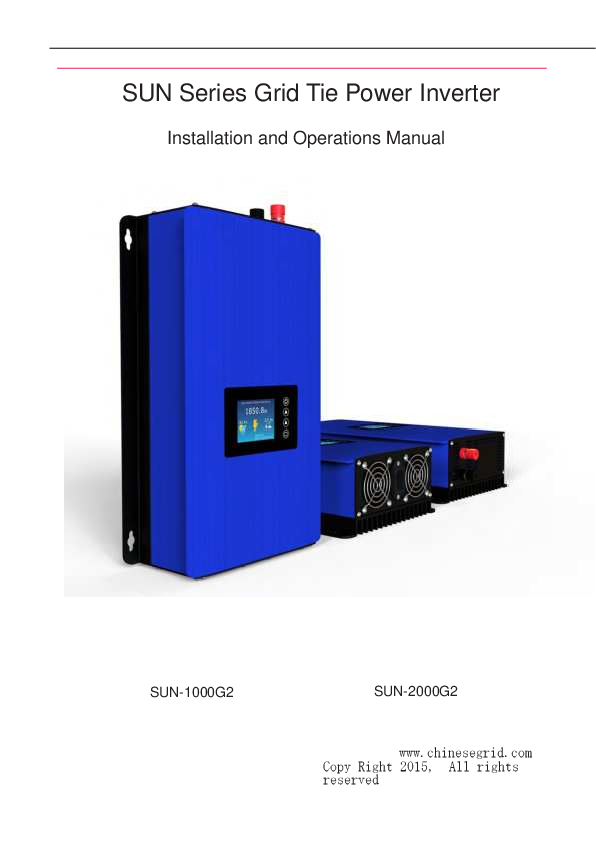
SUN Series Grid Tie Power Inverter
Installation and Operations Manual
Sunshine Grid Tie Inverter Models
Sunshine grid tie inverters are available in a series of models. For detailed information, refer to the Sunshine website: www.chinesegrid.com.
| Model Number | Rated Power (Peak/Continuous) | DC Input Voltage | AC Output Voltage Range | AC Output Frequency Range | Peak Inverter Efficiency | Night Power Consumption |
|---|---|---|---|---|---|---|
| SUN-1000G2-M-U | 1000W/900W | 22V~60V | 90V~140V | 46Hz~65Hz | 90% | 0.5W |
| SUN-1000G2-H-U | 1000W/900W | 45V~90V | 90V~140V | 46Hz~65Hz | 92% | 1.5W |
| SUN-1000G2-M-E | 1000W/900W | 22V~60V | 190V~260V | 46Hz~65Hz | 90% | 0.5W |
| SUN-1000G2-H-E | 1000W/900W | 45V~90V | 190V~260V | 46Hz~65Hz | 92% | 1.5W |
| SUN-2000G2-H-E | 2000W/1800W | 45V~90V | 190V~260V | 46Hz~65Hz | 92% | 1.5W |
Model Name Description: SUN-XXXG2-X-X
- AC Output Voltage Range: "U" is 90V~140V, "E" is 190V~260V
- DC Input Voltage Range: "M" is 22V~60V, "H" is 45V~90V
- "G" is Abbreviation of Grid Tie Power Inverter, 2 means second generation
- The Rated Output Power
- The Title Name of Sunshine Products
Some models also have "B" type, "B" means the model has LCD displayer. For example, the model SUN-1000G2-H-E-B is a Sunshine grid tie power inverter with a rated power of 1000W, a DC input voltage range of 45V~90V, an AC output voltage range of 190V~260V, and an LCD displayer on the inverter panel.
Important Safety Information
Read this First! This manual contains important instructions for the installation and maintenance of the Sunshine Grid Tie Inverter. To reduce the risk of electrical shock and ensure safe installation and operation, follow the safety symbols and instructions throughout this document.
! WARNING: Failure to follow instructions may result in safety hazards or equipment malfunction. Use extreme caution and follow instructions carefully.
! NOTE: Information particularly important for optimal system operation. Follow instructions closely.
Safety Instructions
! WARNING: The body of the Sunshine Grid Tie Inverters acts as a heat sink and can reach temperatures of 80°C. Avoid touching to prevent burns. Perform all electrical installations in accordance with local and National Electrical Codes. Only qualified personnel should install or replace Sunshine Grid Tie Inverters. Do not attempt to repair the inverter as it contains no user-serviceable parts. If the unit fails, contact Sunshine customer service for a Return Merchandise Authorization (RMA) number. Tampering with or opening the inverter will void the warranty. Before installation or use, read all instructions and cautionary markings in the technical description and on the inverter and PV array.
Introduction of Sunshine Grid Tie Inverter
The Sunshine Grid Tie Power Inverter is a technologically advanced inverter for utility-interactive applications. This manual details its safe installation and operation. The integrated system maximizes energy harvest, increases system reliability, and simplifies design, installation, and management.
The small solar grid tie power inverter can obtain solar energy from a solar panel and connect to the grid via its output cables without extra equipment, making installation convenient and reliable. This system, combining the inverter and solar panels, is referred to as 'SGPV'. Solar panels can be mono silicon, polygon silicon, non-crystal film, or other materials that convert solar energy to electricity. The inverter's power should match the solar panels' power. The SGPV's power is defined by its solar panels.
The inverter connects to any utility grid outlet in the house. It monitors the home utility grid's voltage, frequency, and phase, producing a pure sine wave AC power with the same frequency and phase as the grid, but at a slightly higher voltage. Using current-controlled PWM, it regulates output power to the grid. The inverter only outputs power when the home grid is active. When sunlight hits the PV panel, it produces DC voltage, which the inverter converts to AC voltage and feeds into the home grid. If the total power used by household appliances exceeds the inverter's output, the inverter's power is consumed domestically, slowing the power meter. Otherwise, the excess power is fed to the utility grid.
A diagram illustrates a small grid tie power system with the Sunshine Grid Tie Inverter.
Multiple inverters can be connected in parallel for larger systems. Plug-and-play installation is supported.
Advantage of The Sunshine Grid Tie Power System
The Sunshine Grid Tie Power System (SGPV) offers several advantages over traditional grid tie systems:
- Low cost and easy installation: SGPV utilizes building surfaces facing the sun for solar module and inverter installation, requiring minimal maintenance costs.
- Free combination: SGPV can be used as a standalone system or combined into a large solar array. System capacity can be customized. When increasing solar panels, ensure the total power does not exceed the inverter's limits; otherwise, a higher-capacity inverter may be needed.
- Combination of SGPV does not interact: Unlike traditional systems where a single panel's degradation affects the entire series, SGPV's individual inverters are independent. If one panel's performance degrades, it only affects that specific unit, not others in the system.
- Improving the efficiency of the entire solar power system: Traditional systems connect panels in series, with the inverter's MPPT optimizing for the entire series, not individual panels. This can lead to reduced efficiency if panels have varying performance. SGPV inverters have individual MPPT functions, ensuring each panel operates at maximum power, thus increasing overall system efficiency.
- Low power consumption: SGPV inverters use digital ICs and low-power MCUs, resulting in low power consumption, even when multiple inverters are used.
Sunshine Grid Tie Inverter Installation
Follow the instructions in this section to install Sunshine Grid Tie Inverters.
! WARNING: Before installing, read all instructions and cautionary markings in the user manual, on the inverter, and on the PV array.
! WARNING: Perform all electrical installations according to local electrical codes and the National Electrical Code (NEC).
! WARNING: Connect the inverter to the utility grid only after receiving prior approval from the utility company.
! WARNING: Only qualified personnel should connect the inverter to the utility grid.
! WARNING: Installation involves a risk of electric shock. Grounded conductors may become energized during a ground fault.
! WARNING: This unit has fixed trip limits and should not be aggregated above 30 kW on a single Point of Common Connection.
Installation Procedure
Installing a Sunshine Grid Tie Power System involves the following steps:
- Consider the total capacity of the grid tie power system needed.
- Choose applicable solar panels for the Sunshine Grid Tie Inverter.
- Select accessories for the Grid Tie Power System installation.
- Select the correct model of Sunshine Grid Tie Inverter.
- Install solar panels in a suitable place.
- Install the Sunshine Grid Tie Inverter in a suitable place.
- Connect the Sunshine Grid Tie Power System with cables and connectors.
- Ground the system.
- Complete the Sunshine installation map and connect the PV modules.
Detailed installation steps are provided in the following sections and referenced in the installation diagram.
! WARNING: DO NOT connect Sunshine Grid Tie Inverters to the utility grid or energize AC circuits until all installation steps are completed.
Step 1: Considering the total capacity of the grid tie power system
The total capacity depends on your power consumption or how much power you intend to feed to the utility grid. If the total power of appliances used exceeds the system's output, the power is consumed on-site, slowing the power meter. Otherwise, the excess power is fed to the grid. For example, for a house consuming 5KWH daily with 6 hours of irradiation, a 1KW system is suitable. The system can supply power for the whole year. If the grid tie system's output is greater than consumption, excess power is fed to the grid. You can install systems of various capacities (e.g., 500W, 1KW, 2KW), but consider your home's AC system capacity if feeding significant power back to the grid.
Step 2: Choosing applicable solar panels
Solar panels convert light energy into electricity via the photovoltaic effect. Most panels consist of serially connected solar cells (Mono or Poly types). Key technical data includes Efficiency, Pmax (Maximum Power), Vmp (Rated Voltage at Pmax), Imp (Rated Current at Pmax), Voc (Open Circuit Voltage), and Isc (Short Circuit Current).
Example specifications for a 245W solar panel (60 PCS 156×156 Poly solar cells):
- Module Efficiency: 14.8%
- Pmax: 245W
- Vmp: 29.4V
- Imp: 8.34A
- Voc: 36.9V
- Isc: 8.68A
! Note: These specifications are under Standard Test Conditions (STC): Irradiance 1000W/m², Cell temperature 25°C, Air mass AM1.5.
Module Efficiency is the conversion efficiency of light energy to electrical power. Pmax is the maximum power output. Vmp is the voltage at Pmax, and Imp is the current at Pmax. Voc is the open-circuit voltage, and Isc is the short-circuit current. These specifications are sensitive to temperature; refer to I-V curves and temperature dependence data for variations.
I-V Curves and Temperature Dependence: Figure 2 shows I-V curves for a 230W solar panel, illustrating how different irradiance levels affect power output. Figure 3 shows the temperature dependence of Isc, Voc, and Pmax, indicating that Pmax and Voc have negative temperature coefficients, as does Vmp.
Choosing solar panels
Key specifications for selecting solar panels are Pmax, Voc, Vmp, and Isc:
- The total Pmax of the solar panels should be equal to or less than the inverter's Rated Power (Peak).
- The total Voc of the solar panels must be less than the inverter's maximum DC input range. For parallel connections, all panels must have the same Voc. For series connections, the Isc of each panel must be the same, and the total Voc is the sum of individual Voc values. Connecting panels with identical specifications is recommended.
- The total Vmp of the solar panels should be above the inverter's minimum DC input range. The connection method principle is similar to Voc.
Step 3: Selecting Accessory for Grid Tie Power System installation
Accessories for grid tie power system installation include:
- DC cables for connecting solar panels and inverters.
- Connectors (e.g., MC4 Connectors, connectors for parallel connecting).
- AC cables.
- Power meter (Optional).
- Bracket for solar panels installation (not included in this manual).
Selecting DC cables
Cable specifications should be based on the total power of the solar panels and the connection method. Calculate the maximum current (Imax) using formulas: Tlmp = TPmax/TVmp or Tlmp = Imp×N (where N is the number of parallel solar panels). Refer to Table 2 for suitable cable sizes based on Imax. Outdoor-rated solar cables are recommended.
Selecting Connectors
Connectors like MC4 and parallel connectors are used for connecting solar panels and inverters.
Selecting AC cables
AC cables are supplied with inverters, with types varying by country and local standards. Provide installation location details to the dealer.
Step 4: Selecting Correct Model of Sunshine Grid Tie Inverter
After determining the connection method for the solar panels (Steps 1-3), select the appropriate inverter model. The inverter's DC input voltage range must match the solar array's DC output voltage. The inverter's rated power should match the solar panel array's total power, and its AC output must comply with the utility grid standard.
Example of 1KW grid tie power system installation:
Assuming a house with 5KWH daily consumption and 5 hours of irradiation, a 1KW Sunshine Grid Tie Power System is suitable for a 230V/50Hz utility grid.
Choosing Applicable Solar Panels: For a 1KW system, using four 240Wp-250Wp poly panels (60 cells) is economical. With panels having specifications like Pmax: 245W, Vmp: 29.4V, Imp: 8.34A, Voc: 36.9V, Isc: 8.68A, the total Pmax is 245Wp × 4 = 980Wp, suitable for a 1KW SUN-1000G model inverter.
! Notes: Pmax is under STC; actual power varies with irradiation and temperature. Real output may not reach Pmax consistently.
Selecting Accessory for Grid Tie Power System installation: For connecting 4 solar panels, MC4 connectors and parallel connectors are needed. For DC cables:
- Method 1 (Parallel connection): Tlmp = 33.3A. Requires AWG6 cables.
- Method 2 (Series connection in pairs): Tlmp = 16.7A. Requires AWG9 cables.
Choosing smaller diameter cables (AWG9) is more cost-effective.
Selecting correct model of Sunshine Grid Power Inverter:
- Method 1 (Parallel connection): TVmp=29.4V, TVoc=36.9V. Requires SUN-1000G2-M-E (DC input voltage range 22V-60V).
- Method 2 (Series connection in pairs): TVmp=29.4V×2=58.8V, TVoc=36.9V×2=73.8V. Requires SUN-1000G2-H-E (DC input voltage range 45V-90V).
Diagrams for Method 1 (Figure 4) and Method 2 (Figure 5) are provided. Method 2 is preferred due to thinner, less expensive DC cables and fewer connectors.
Installing larger capacity of grid tie power system
To install larger capacity systems, multiple inverters can be stacked. For a 2KW system, two 1KW inverters can be used, connecting their AC outputs to the utility grid. This is called a "Stackable System" (Figure 6).
! WARNING: Do not connect the DC input terminals of one Sunshine Grid Tie Power Inverter to another. This prevents the inverters from finding the correct maximum power point (MPP), reducing system efficiency (Figure 7).
Installing Sunshine Grid Tie Power System to Three Phases Utility Grid
For larger capacity systems, connecting all power to a single utility grid phase can cause imbalance. Install the system across three phases to balance the fed power. Figure 8 illustrates a three-phase grid tie power system where each phase receives power from separate inverter units.
Starting DIY from small grid tie power system
For those new to grid tie systems, starting with a small DIY system is recommended. The SUN-250G is the smallest SUN series inverter, with a rated output of 225W and peak of 250W. A small system can be built using this inverter with a single 245Wp solar panel or two 120Wp panels (total Pmax < 250Wp). Installation requires only DC cables and a few connectors (Figure 9 and Figure 10).
Layout of Sunshine Grid Tie Power Inverter
Refer to Figure 13 for the SUN-1000G-X-X layout and Figure 14 for the SUN-2000G2-X-X layout with LCD displayer.
SUN-1000G2-X-X Layout (Figure 13):
- DC Input Panel
- AC Output Panel
SUN-2000G2-X-X Layout (Figure 14):
- 1. DC Input Positive Terminal: Connects to the positive wire of solar cables from the solar panels.
- 2. DC Input Negative Terminal: Connects to the negative wire of solar cables from the solar panels.
- 3. AC socket: Connects the inverter to the public grid via the AC cable.
- 4. AC Output Panel
- 5. Cooling fans.
Inverter Display Instruction
The inverter display shows various information, including grid waveform, energy menu, power view, and settings.
- Set Menu: Access settings like LCD backlight (always on or auto turn off after 3 minutes).
- Limiter Function: The inverter has internal and external limiter functions to prevent excess power export. In internal limiter mode, output power is determined by load. External limiter mode requires a separate module. Contact the supplier for details.
The display interface shows settings for Limiter Mode, LCD backlight, and Battery Discharge Current/Power Modes (not yet developed).
! Notes: Save settings after reconfiguring working mode or backlight. Battery discharge modes are not yet developed.
Interface Descriptions:
- Grid Waveform: Shows real-time grid voltage and frequency.
- Energy Menu: Displays daily power generation curves, including Today KWH and Total KWH.
- Power View: Shows real-time power, PV input voltage, internal temperature, date, and time.
- Clock And Date Setting: Allows setting the clock and date. Save settings before exiting.
Technical Data of SUN Series Grid Tie Power Inverter
Table 3 provides common specifications for SUN Series Grid Tie Power Inverters.
| SUN-XXXG2-M-X | SUN-XXXG2-H-X | |
|---|---|---|
| INPUT DATA (DC) | ||
| Maximum Input DC | 60 V | 90 V |
| Peak power Tracking Voltage | 25V - 60 V | 45V - 90 V |
| Operating DC Voltage Range | 22 V - 60 V | 50V - 90 V |
| Peak Inverter Efficiency | 99% | 99% |
| OUTPUT DATA (AC) | ||
| Nominal | SUN-XXX-X-E: 230V/185V-265V SUN-XXX-X-U: 115V/95V-140V |
SUN-XXX-X-E: 230V/185V-265V SUN-XXX-X-U: 115V/95V-140V |
| Frequency Range | 47.5-51.5 for 50hz, 59.3-60.5 for 60hz | |
| Power Factor | >0.95 | |
| Output Waveform | Pure Sine Wave | |
| CHARACTERISTIC DATA | ||
| MPPT Effeciency | 99% | |
| Over Current Protection | Yes | |
| Over Temperature Protection | Yes | |
| Reverse Polarity Protection | Yes | |
| Anit-Island Protection | Yes | |
| Stackable | Just for AC Output | |
| Operating Temperature Range | -20℃ ~ 45°C | |
| Storage Temperature Range | -40°C ~ 65°C | |
Other electrical specifications for each model are listed in Table 1.
Weight and Dimension of SUN series Grid Tie Power Inverter
| Model | SUN-1000G2-X-X | SUN-2000G2-X-X |
|---|---|---|
| Net Weight | 3.6Kg | 6.0Kg |
| Gross Weight | 4.8Kg | 7.2Kg |
| Dimension (Package) | 400mm×270mm×140mm | 520mm×310mm×160mm |
Outline Drawing of SUN Series Grid Tie Power Inverter
Figure 17 shows the outline drawing of the SUN-1000G2-X-X, and Figure 18 shows the outline drawing of the SUN-2000G2-X-X.
SUN-1000G2-X-X Outline Drawing (Figure 17):
- Includes dimensions for the unit, DC Input Panel, and AC Output Panel.
SUN-2000G2-X-X Outline Drawing (Figure 18):
- Includes dimensions for the unit, DC Input Panel, and AC Output Panel.
Troubleshooting
Qualified personnel can use the following troubleshooting steps if the Sunshine Grid Tie Power System does not operate correctly.
! WARNING: Do not attempt to repair the Sunshine Grid Tie Inverter; it contains no user-serviceable parts. Contact Sunshine customer service for RMA and replacement if the unit fails.
Status LCD Indications and Error Reporting
The inverter's LCD indicates status and errors in red letters.
Example Display: SUN-2000G-SUN(45-90V)Ver5.0, 0.0W, 26.5V, 216.5V, Input Voltage Too Low, Temp:63C, Date:2015-5-14 07:07:47
- 1) Overtemperature: Inverter stops at 75°C. Ensure good ventilation.
- 2) Input Voltage Too Low: Indicates low DC input voltage or poor DC connection. Measure solar array output voltage.
- 3) Input Voltage Too High: Indicates high DC input voltage. Adjust connection method as described in the manual.
- 4) Grid Error: Indicates no AC connection to the utility grid, or AC voltage/frequency is out of specification. Check AC cable and utility grid outlet. Use a multimeter to measure AC voltage/frequency.
- 5) Dumping Load Shorted: Indicates an internal or external short circuit.
- 6) Starting Voltage Too Low: Indicates low solar array output voltage. Reconfigure panels or choose suitable panels to ensure the output voltage is within the inverter's input range.
! WARNING: Never disconnect DC wire connectors under load. Ensure no current is flowing before disconnecting. Use an opaque covering to cover the module before disconnecting.
AC Output Current Waveform and PF Test Of 2000W Model
Testing of the 2000W model at near full load showed a good pure sine wave output on the oscilloscope, with a Power Factor (PF) of 99.8%.
A waveform display shows a sine wave with a frequency of 50.00 Hz.
A measurement instrument displays: Voltage 229.7V, Current 8.405A, PF 0.998, Power 1.92W.


