Philips Fisio 820 Service Manual 825 SM En
User Manual: philips Fisio 820 - Service Manual Free User Guide for Philips Mobile Phone, Manual
Open the PDF directly: View PDF ![]() .
.
Page Count: 71
Départ. Technical support- CM640 PROCEDURE COMPANY RESTRICTED
PHILIPS Consumer
Communications
Centre du Mans
Service Repair Support VY-V-640-82x
Page : 1 of 71
Langue : EN
Date : 25/02/03
PHILIPS ELECTRONICS N.V. 1999 by Toko (toko@gsm-free.org)
All rights reserved. Reproduction in whole
or in part is prohibited without the written
consent of the copyright owner.
SERVICE MANUAL
Repair for Cellular Telephone
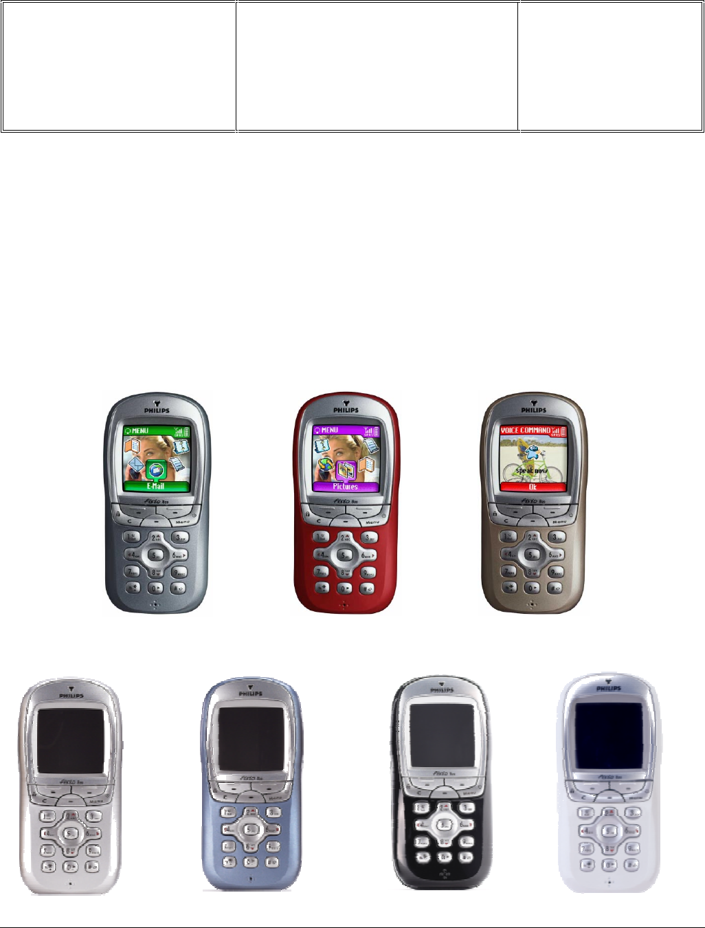
Fisio 820 - Fisio 825
LEVEL 2

Départ. Technical support- CM640 PROCEDURE COMPANY RESTRICTED
PHILIPS Consumer
Communications
Centre du Mans
Service Repair Support VY-V-640-82x
Page : 2 of 71
Langue : EN
Date : 25/02/03
PHILIPS ELECTRONICS N.V. 1999 VY-V-640-82x
All rights reserved. Reproduction in whole
or in part is prohibited without the written
consent of the copyright owner.
SERVICE Manual
Last updates :
DATE MODIFICATION PAGE
08/04/02 CREATION
26/08/02 Window assembly instructions Page 64-65
14/02/03 - Add Fisio 825 picture
- Add Fisio 825 test consumption
- Part list chapter
Page 1
Page 42
Page 70
25/02/03 Cradle 12NC code correction Page 5

Départ. Technical support- CM640 PROCEDURE COMPANY RESTRICTED
PHILIPS Consumer
Communications
Centre du Mans
Service Repair Support VY-V-640-82x
Page : 3 of 71
Langue : EN
Date : 25/02/03
PHILIPS ELECTRONICS N.V. 1999 VY-V-640-82x
All rights reserved. Reproduction in whole
or in part is prohibited without the written
consent of the copyright owner.
CONTENTS
1.0 PURPOSE .................................................................................................................................................................5
2.0 SCOPE ......................................................................................................................................................................5
3.0 REFERENCE............................................................................................................................................................5
4.0 GLOSSARY/ACRONYM LIST ...............................................................................................................................5
5.0 TEST EQUIPMENT AND TOOLS..........................................................................................................................5
6.0 TEST AND INSPECTION PLAN ............................................................................................................................6
6.1 User Interface Test..................................................................................................................................................6
6.2 RF Test ...................................................................................................................................................................6
7.0 BEFORE STARTING...............................................................................................................................................8
7.1 Description Of The Transceiver...............................................................................................................................8
7.2 Description Of The Display.....................................................................................................................................9
7.3 Using The Carousel...............................................................................................................................................10
7.4 Inserting The MICRO-SIM Card...........................................................................................................................11
7.5 Inserting The Battery.............................................................................................................................................11
7.6 Removing The Battery...........................................................................................................................................12
7.7 Charging The Battery............................................................................................................................................12
7.8 W@P Introduction ................................................................................................................................................13
7.9 GPRS Introduction................................................................................................................................................15
7.10 BLUETOOTH Introduction...................................................................................................................................22
7.11 E-MAIL Introduction ............................................................................................................................................30
8.0 TEST PROCEDURES............................................................................................................................................31
8.1 Initial Functional Check for Fisio 820 & Fisio 825.................................................................................................31
8.2 RF Test .................................................................................................................................................................35
8.3 Battery Charging (IGN : Ignition) / Current Consumption......................................................................................41
8.4 W@P Test Procedure ............................................................................................................................................43
8.5 Bluetooth Test Procedure ......................................................................................................................................49
8.6 E-MAIL Test Procedure........................................................................................................................................50
9.0 ASSEMBLY / DISMANTLEMENT PROCEDURES............................................................................................54
9.1 Dismantlement......................................................................................................................................................54
9.2 Assembly..............................................................................................................................................................60
Exploded view of the transceiver ......................................................................................................................................66
10.0 SOLUTIONS IN CASE OF PROBLEMS DURING THE TESTS ........................................................................68
11.0 RECOMENDED PART LIST CT9888 FISIO820................................................................................................70

Départ. Technical support- CM640 PROCEDURE COMPANY RESTRICTED
PHILIPS Consumer
Communications
Centre du Mans
Service Repair Support VY-V-640-82x
Page : 4 of 71
Langue : EN
Date : 25/02/03
PHILIPS ELECTRONICS N.V. 1999 VY-V-640-82x
All rights reserved. Reproduction in whole
or in part is prohibited without the written
consent of the copyright owner.
12.0 RECOMENDED PART LIST CT9889 FISIO825................................................................................................70
ANNEX 1............................................................................................................................................................................71

Départ. Technical support- CM640 PROCEDURE COMPANY RESTRICTED
PHILIPS Consumer
Communications
Centre du Mans
Service Repair Support VY-V-640-82x
Page : 5 of 71
Langue : EN
Date : 25/02/03
PHILIPS ELECTRONICS N.V. 1999 VY-V-640-82x
All rights reserved. Reproduction in whole
or in part is prohibited without the written
consent of the copyright owner.
1.0 PURPOSE
This document establishes the functional test and inspection procedures for the first level service repair of the
FISIO 820 transceiver (CT9888) and FISIO 825 transceiver (CT9889).
2.0 SCOPE
The test plan is applicable to all levels of service repair of the FISIO 820 transceiver (CT9888) and FISIO 825
transceiver (CT9889).
3.0 REFERENCE
None.
4.0 GLOSSARY/ACRONYM LIST
Window or Bezzel Protective plastic over the LCD display
SW Software
PN Hardware Configuration of the Mobile
CN Matrix for Types of SW used on the different hardware
HW Hardware
ASC Authorized Service Center
NSC National Service Center
Test SIM Card Used for functionality of PHILIPS Mobile Phones
Test SIM Card « SP » SIM Card used to simulate the user interface and enable radio tests
5.0 TEST EQUIPMENT AND TOOLS
Equipment / Tools
- Production Test SIM Card - Part No. : 4311 255 00781
- Test SIM Card « SP » - Part No. : 4311 255 00782
- W@b dismantling tool - Part No. : 4311 255 21325
- Digital Multimeter - Recommended Model : Fluke (Specification: with current reading in mA.)
- Digital Radiocommunication Tester.
- Coupling system with shielded chamber.
Or
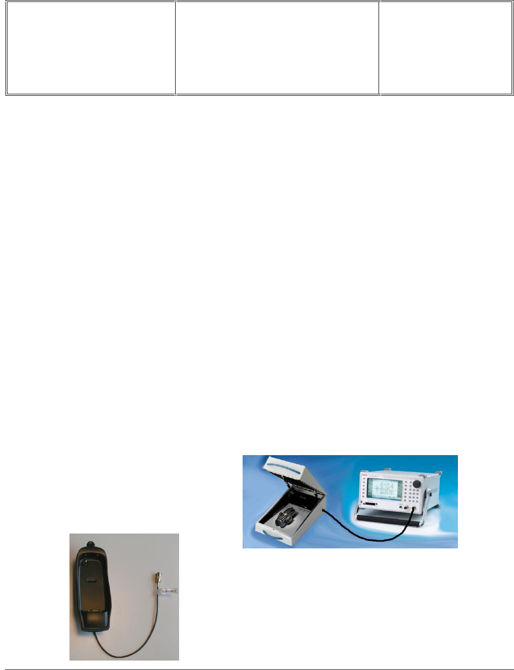
- Product cradle Ref: CKFR82/P - Part No.: 9911 240 34509
Départ. Technical support- CM640 PROCEDURE COMPANY RESTRICTED
PHILIPS Consumer
Communications
Centre du Mans
Service Repair Support VY-V-640-82x
Page : 6 of 71
Langue : EN
Date : 25/02/03
PHILIPS ELECTRONICS N.V. 1999 VY-V-640-82x
All rights reserved. Reproduction in whole
or in part is prohibited without the written
consent of the copyright owner.
6.0 TEST AND INSPECTION PLAN
The test plan is derived from the Product Test Reference of FISIO 820 and FISIO 825.
6.1 User Interface Test
Use the Test SIM Card to test the transceivers as follows :
• On/Off button
• LCD Backlight
• Keyboard Test
• Buzzer Test
• Vibrator Test
• Audio Test
• Antenna
Test ( to measure the radiated power level. Not necessary when using an antenna coupler)
• LCD
• IMEI
• Tester Status/Eeprom Status
With a fast Charger connected with the PRODUCT’s bottom connector , check the full scrolling from one mode to
the next when charging IGN (Ignition) – Battery.
6.2 RF Test
The purpose of the radio test is to prove that the tested phone is compliant to the Standard.
The radio test must be performed with a
Digital Radio Test Set. The mobile has to
be set on the antenna coupler inside the
shielded chamber.
Or It can be tested using the product
cradle (in this case a measurement of
the power radiated by the antenna has
to be performed)

Départ. Technical support- CM640 PROCEDURE COMPANY RESTRICTED
PHILIPS Consumer
Communications
Centre du Mans
Service Repair Support VY-V-640-82x
Page : 7 of 71
Langue : EN
Date : 25/02/03
PHILIPS ELECTRONICS N.V. 1999 VY-V-640-82x
All rights reserved. Reproduction in whole
or in part is prohibited without the written
consent of the copyright owner.
Use the Test SIM Card « SP »to test the following RF items
• GSM 900 / DCS 1800 band
• GPRS capability
• Bluetooth connectivity
In case the RF tester is not suitable for GPRS tests, GSM900/DCS1800 test may be considered as sufficient
provided that the sensivity tests are strengthened by reducing the RF level down to -104dBm.
Bluetooth tests consists only in a pairing test with another Bluetooth device (e.g. Bluetooth headset)
RRM RLC / MAC
L1
[Sequencer]
HARDWARE LAYER
[Function book for DSP control]
DSP
BER
BLER CS1 to CS4
This reasoning is based on the fact that all
the protocol steps (GPRS attach, GPRS
detach, …) are achieved on the GSM/DCS
bands and validated by Philips Approval
department.
The new parameter to check, introduced by
GPRS, would be BLER (Blocks Error Rate).
As shown on the drawing, it involves more
modules than BER
Signals paths
BLER compared to BER
Départ. Technical support- CM640 PROCEDURE COMPANY RESTRICTED
PHILIPS Consumer
Communications
Centre du Mans
Service Repair Support VY-V-640-82x
Page : 8 of 71
Langue : EN
Date : 25/02/03
PHILIPS ELECTRONICS N.V. 1999 VY-V-640-82x
All rights reserved. Reproduction in whole
or in part is prohibited without the written
consent of the copyright owner.
7.0 BEFORE STARTING
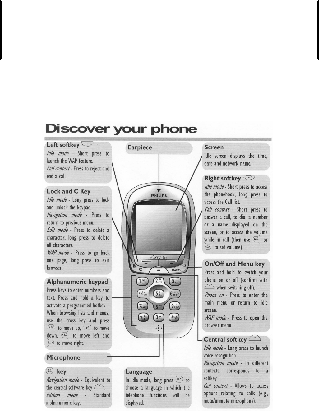
7.1 Description Of The Transceiver
Départ. Technical support- CM640 PROCEDURE COMPANY RESTRICTED
PHILIPS Consumer
Communications
Centre du Mans
Service Repair Support VY-V-640-82x
Page : 9 of 71
Langue : EN
Date : 25/02/03
PHILIPS ELECTRONICS N.V. 1999 VY-V-640-82x
All rights reserved. Reproduction in whole
or in part is prohibited without the written
consent of the copyright owner.
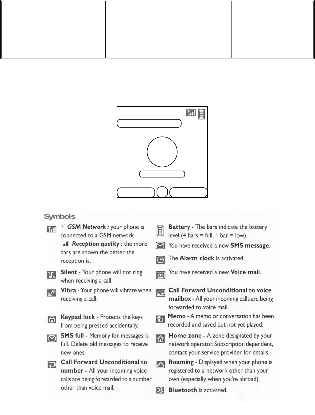
7.2 Description Of The Display
OPERATOR
DATE
CLOCK
ICONS BAR
Names
WAP
Départ. Technical support- CM640 PROCEDURE COMPANY RESTRICTED
PHILIPS Consumer
Communications
Centre du Mans
Service Repair Support VY-V-640-82x
Page : 10 of 71
Langue : EN
Date : 25/02/03
PHILIPS ELECTRONICS N.V. 1999 VY-V-640-82x
All rights reserved. Reproduction in whole
or in part is prohibited without the written
consent of the copyright owner.
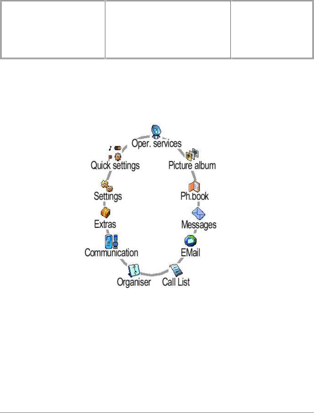
7.3 Using The Carousel
The carousel is a circular loop of icons displayed on the screen. These icons provide access to the different menus
and sub menus used to operate your phone.
Départ. Technical support- CM640 PROCEDURE COMPANY RESTRICTED
PHILIPS Consumer
Communications
Centre du Mans
Service Repair Support VY-V-640-82x
Page : 11 of 71
Langue : EN
Date : 25/02/03
PHILIPS ELECTRONICS N.V. 1999 VY-V-640-82x
All rights reserved. Reproduction in whole
or in part is prohibited without the written
consent of the copyright owner.
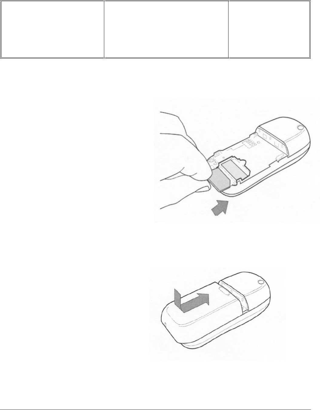
7.4 Inserting The MICRO-SIM Card
7.5 Inserting The Battery
Place the battery on the back of the phone
(battery connectors downwards), then push it
into place until the latch catches
First remove the SIM card from its card holder.
Slide it into its slot, microchip facing
connectors, until its stops. Be careful that the
clipped corner is in the identical position as on
the drawing.
Départ. Technical support- CM640 PROCEDURE COMPANY RESTRICTED
PHILIPS Consumer
Communications
Centre du Mans
Service Repair Support VY-V-640-82x
Page : 12 of 71
Langue : EN
Date : 25/02/03
PHILIPS ELECTRONICS N.V. 1999 VY-V-640-82x
All rights reserved. Reproduction in whole
or in part is prohibited without the written
consent of the copyright owner.
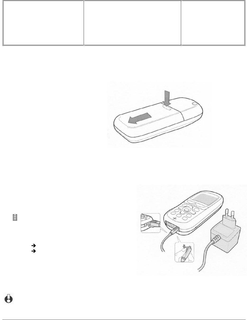
7.6 Removing The Battery
7.7 Charging The Battery
Once the battery is clipped on the phone, plug the charger into the right hand socket at the base of the phone as
shown on the drawing.
If the battery is completely flat, the battery icon will only reappear after 2 or 3 minutes of charging.
Press below the rubber (Philips logo)
and slide the battery downwards
Then plug the transformer unit into a main AC power
socket with easy access.
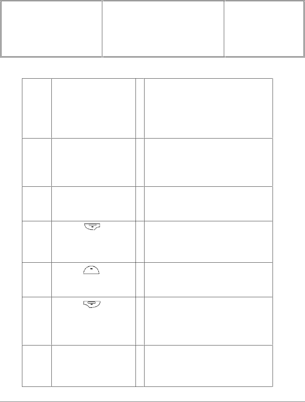
The symbol indicates the state of charge :
During charging the 4 charge indicators change; each bar
represents around 25% of charge.
Bars moving Battery is charging
Bars steady Battery is fully charged
Battery outline flashing (see chapter 9)
When the battery is charged, remove the connector by
pressing the release button on top of the connector
Départ. Technical support- CM640 PROCEDURE COMPANY RESTRICTED
PHILIPS Consumer
Communications
Centre du Mans
Service Repair Support VY-V-640-82x
Page : 13 of 71
Langue : EN
Date : 25/02/03
PHILIPS ELECTRONICS N.V. 1999 VY-V-640-82x
All rights reserved. Reproduction in whole
or in part is prohibited without the written
consent of the copyright owner.
7.8 W@P Introduction
The purpose of W@p (Wireless Application Protocol) is to enable easy and fast delivery of relevant information and
services to mobile users. However, mobile Internet does not mean navigating on the Internet with a wireless device
but rather to access to some services in a mobile context.
The W@P architecture was designed to enable standard Internet servers to provide services to wireless devices.
The W@P wireless protocol is based on Internet standards such as HTTP and TLS but has been optimized
according to the constraints of the wireless terminals: low memory capacity, small screen size
and of the network: limited bandwidth.
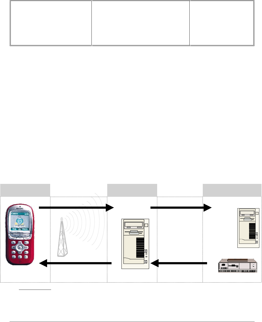
The W@P architecture is made up of 4 technological parts which are necessary for accessing W@P services on a
mobile phone. These are:
W@P navigator or browser
Mobile operator network
W@P gateway / W@P server
Web server
* Subscription
The customer has to contact his Network Operator to inquire about his subscription and the options he can
subscribe to. Generally the customer just have to request his W@P access to his provider and he will not be
charged for that.
Customer Gateway Server
1.0 Encoded
Request
2.0 Request
3.0 Answer
4.0 Encoded
Answer
Content
Generation
Encoder/
Decoder

Départ. Technical support- CM640 PROCEDURE COMPANY RESTRICTED
PHILIPS Consumer
Communications
Centre du Mans
Service Repair Support VY-V-640-82x
Page : 14 of 71
Langue : EN
Date : 25/02/03
PHILIPS ELECTRONICS N.V. 1999 VY-V-640-82x
All rights reserved. Reproduction in whole
or in part is prohibited without the written
consent of the copyright owner.
* W@P parameters
Parameters have to be set in the mobile phone in order to access W@P services . However, there are two
cases depending on the commercial offer:
* Transceiver sold via an operator package(with subscription included):
- Parameters cannot be accessed from the W@P settings menu of the mobile phone:
The transceiver is W@P locked. The W@P connections will always be made from the
operator W@P homepage and search engines will be available. The customer will have to
ask for a password from his/her operator to unlock the W@P settings.
- Parameters can be accessed from the W@P settings menu of the mobile
phone:
The customer changes the W@P parameters according to his/her own convenience.
* Retail transceiver(without subscription included):
- Phones are configured by the manufacturer with no W@P parameter. The end user has
to ensure that the W@P functionality and a data/fax options have been subscribed.
The end user has also to set the W@P parameters by asking for them from
his/her operator or by using parameters of another company (available on
Internet, newspaper etc.)
Detailed parameters
Phone Number (or dial-up number) : to establish a connection with the Internet Service Provider
Login (or User Name) : if requested by your ISP
The password : if requested by your ISP
IP address for the Gateway : for communications between Internet Service Provider and Gateway
& Port Number (for a secure or non secure connection)
Home page address(or URL address): for communications between Gateway and Web server
Please note that it is important to respect small and capital letters according to your operator instructions.
It is also possible that your provider does not require the Login and/or Password.

Départ. Technical support- CM640 PROCEDURE COMPANY RESTRICTED
PHILIPS Consumer
Communications
Centre du Mans
Service Repair Support VY-V-640-82x
Page : 15 of 71
Langue : EN
Date : 25/02/03
PHILIPS ELECTRONICS N.V. 1999 VY-V-640-82x
All rights reserved. Reproduction in whole
or in part is prohibited without the written
consent of the copyright owner.
7.9 GPRS Introduction
7.9.1 Presentation
The GPRS does not constitute to him alone a separate mobile network, but a supplementary layer added to a
existing GSM network.
It can be thus settled without any supplementary license. This means that all the operators who have a GSM
license can develop their network towards it.
Furthermore, the GPRS uses wavebands attributed to the GSM. that means a band in the 900 MHz, the other one
in the 1800 MHz and finally the third for the USA, in the 1900 MHz
The GPRS, also called GSM 2+, rests on the transmission of data packets. This principle, already held for example
for the protocol X.25, allows to allocate to the other communications, the time-outs of a first communication (wait of
an answer to an Internet request for example).
Conceived to reuse at most the existing GSM infrastructures, the expansion of the GPRS requires the
implementation of a network infrastructure based on the data packets routing and the introduction of bridges to lean
on existing GSM networks.
This technology, capable of supplying transfer rates rising up to 115 kb/s (against 9,6 kb/s for the GSM), offers
interesting features:
• Several channels can be allocated to a single user;
• Several users can share a single channel;
• The transmission rate is independent from rising and downward links.
7.9.2 Services / Possibilities / Limitations
Domains of application
While the WAP stops in the consultation of the Internet pages, the GPRS allows to widen the service offer. Besides
the access to Internet (or Intranet), from the traditional mobiles phones, it allows a better access to e-mails
containing joined files.
A rate higher than the wired public network
Today, the transmission rate of a standard GSM network in "connected" mode does not overtake 9,6 kbit/s, even
14,4 kbit/s by establishment of specific software. It is five times less fast compared to the standard wired network,
which authorises 56 kbit/s with a V90 modem.

Départ. Technical support- CM640 PROCEDURE COMPANY RESTRICTED
PHILIPS Consumer
Communications
Centre du Mans
Service Repair Support VY-V-640-82x
Page : 16 of 71
Langue : EN
Date : 25/02/03
PHILIPS ELECTRONICS N.V. 1999 VY-V-640-82x
All rights reserved. Reproduction in whole
or in part is prohibited without the written
consent of the copyright owner.
With the GPRS, a transmission rate included between 40 and 115 kbit/s is available. Everything depends on the
number of virtual canals or " time slots " used, and on coding scheme (CS1 to CS4). GPRS acts on the
compression of the data as a multiplier of transmission rate. In 3+1 multislots mode (three slots for the network
towards mobile, and one slot for the mobile towards network), it allows a transmission rate of 40 kbit/s with a CS2
coding scheme.
With (8+1)multislots using the CS4 coding scheme, one achieves in practice 115 kbit/s (in theory 175 kbit/s).
GPRS re-uses the existing GSM infrastructure, notably by keeping the current network of base stations ( BTS),
upgrading the BTS software.
Average time to send an E-mail with a 10 pages attached document :
Standard Rate Time elapsed
Current GSM 9,6 kbit/s 7 min.
Standard Modems (V90) 57,6 kbit/s 70 sec.
RNIS 128 kbit/s 31 sec.
GPRS 144 bit/s * 28 sec.
EDGE 384 kbit/s * 10 sec.
UMTS 2 Mbit/s 2 sec.
* : in optimal conditions
Three types of air terminals
Three types of air terminals were defined to meet the needs of the GPRS: the basic model (class B) is foreseen for
the voice and the data in not simultaneous mode. The professional or industrial model (class C) is data exclusively
(the air terminal is used as a modem). Finally the up-market (class A) is compatible voice/data simultaneously. This
class A terminal is problematic. The power of calculation required at the moment has a strong incidence on its
production cost and makes it dissuasive.
In the GPRS standard, three new types of mobile terminal have been defined:
Class A terminal, which supports simultaneous circuit-switched and packed-switched traffic;
Class B terminal, which supports either circuit-switched or packed-switched traffic (simultaneous network
attachment) but does not support both kinds of traffic simultaneously;
Class C terminal, which is attached either as a packed-switched or circuit-switched terminal.
The terminal types are further differentiated by their ability to handle multislot operations. The terminal can use
from 1 up to 8 time slots on the uplink and on the downlink channel. 18 service classes are defined depending on
the number for support time slots.
Départ. Technical support- CM640 PROCEDURE COMPANY RESTRICTED
PHILIPS Consumer
Communications
Centre du Mans
Service Repair Support VY-V-640-82x
Page : 17 of 71
Langue : EN
Date : 25/02/03
PHILIPS ELECTRONICS N.V. 1999 VY-V-640-82x
All rights reserved. Reproduction in whole
or in part is prohibited without the written
consent of the copyright owner.
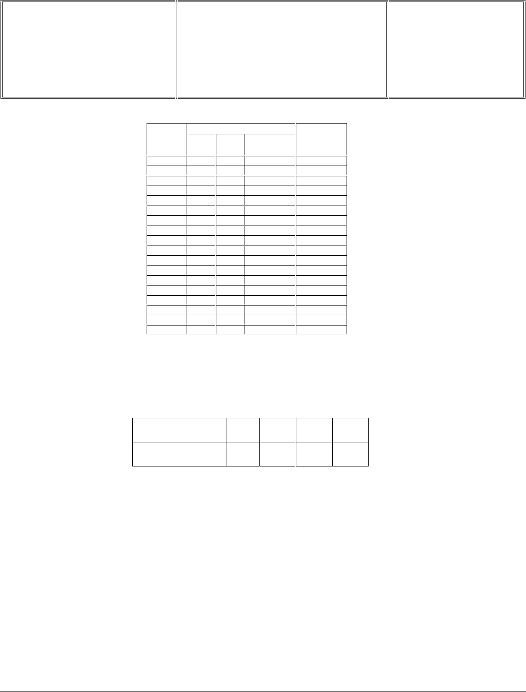
Max Number of Slots
Servic
e Class Max
Rx Max
Tx Total
available
Multislot
type
1112 1
2213 1
3223 1
4314 1
5224 1
6324 1
7334 1
8415 1
9325 1
10 425 1
11 435 1
12 445 1
13 336 2
14 448 2
15 5510 2
16 6612 2
17 7714 2
18 8816 2
Fig. 1 Service Classes - Multislot operations
Four different channel-coding schemes have been defined for GPRS to make optimum use of varying radio
conditions. Usage of higher coding schemes allows to send more data in the same number of time slots.
Channel Coding
Scheme CS-1 CS-2 CS-3 CS-4
Data rate per
timeslot (kbps) 9.05 13.4 15.6 21.4
Fig. 2 GPRS Coding Schemes
Philips Fisio820 features GPRS Class B. With GPRS Class B, if you receive incoming calls while in the middle of a
data session, you receive a notification; and vice versa.
Philips Fisio820 is enabled to support GPRS up to Class10 (4Rx, 2Tx) [depending on networks developments].
GPRS Class10 enables to receive information at least 4 times faster than a standard GSM connection and to send
them 2 times faster. That is why GPRS Class 10 is particularly suitable for surfing on the WAP pages, exchanging
emails or using your phone as a modem for Internet surfing, Intranet browsing or file transfer.
Philips Fisio820 is SMG31bis - Coding schemes 1, 2, 3 et 4.

Départ. Technical support- CM640 PROCEDURE COMPANY RESTRICTED
PHILIPS Consumer
Communications
Centre du Mans
Service Repair Support VY-V-640-82x
Page : 18 of 71
Langue : EN
Date : 25/02/03
PHILIPS ELECTRONICS N.V. 1999 VY-V-640-82x
All rights reserved. Reproduction in whole
or in part is prohibited without the written
consent of the copyright owner.
7.9.3 Technical characteristics
Circuit switched mode or virtual access
The first advantage of the GPRS is to allow a better use of the radio and technical resources. While the GSM works
in "connected" mode, called also "circuit-switched" mode, the GPRS uses for its part the virtual connection mode.
In "virtual" mode, the resources are shared. The transmission channel is never allocated to a unique user, but
shared between several users. Every user has it when he needs it and only in that case. The rest of the time they
are available. The circuit switched mode corresponds to the functioning of a GSM line or still a standard telephone
line. It consists in establishing a physical link between two points or two correspondents. Once the number is
dialled, a circuit is permanently allocated to the communication, without any sharing with the other customers. This
mode of functioning which does not take into account periods of silence, when no data is passed on, does not
optimise at its best the radio resources.
The GPRS puts in evidence the more important role of the network administrator. In a GSM infrastructure the role
of the administrator amounts to affect physical resources at the beginning of every communication. With the GPRS,
its role is more important. It consists in assigning, in real time, the physical resources (memories and electronic
circuits), in managing the radio resources, and in affecting them according to the demand.
The GPRS settles down on the existing GSM network
The GPRS-system is built upon the existing GSM-infrastructure. Basic stations undergo no modification with
exception of the specific software, that can be installed by downloading.
Next, the Basic Stations Controller (BSC) should be doubled by a Packet Controller Unit (PCU).
Then comes the path intended for data packets, its composed of :
- The Serving GPRS Specific Node (SGSN) , equivalent of the Mobile Switch Controller ( MSC), which aims to
check subscribers registering , to authenticate them and to authorise the communications,
- The Access module (GGSN) to the IP world (Internet or Intranet).
GGSN and SGSN are described later.
Départ. Technical support- CM640 PROCEDURE COMPANY RESTRICTED
PHILIPS Consumer
Communications
Centre du Mans
Service Repair Support VY-V-640-82x
Page : 19 of 71
Langue : EN
Date : 25/02/03
PHILIPS ELECTRONICS N.V. 1999 VY-V-640-82x
All rights reserved. Reproduction in whole
or in part is prohibited without the written
consent of the copyright owner.
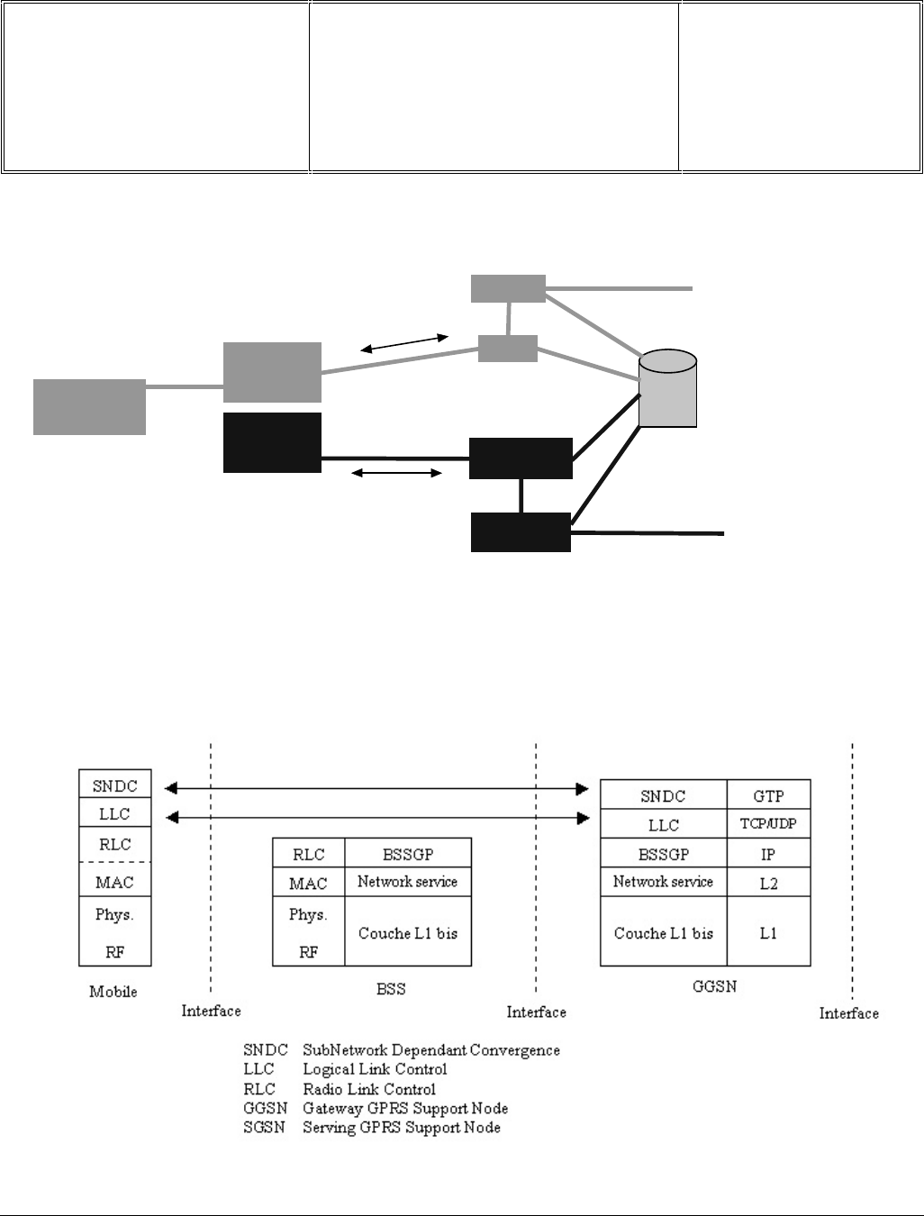
7.9.4 Network Architecture
GPRS network architecture
The constituents of the GPRS network
There is the software layers architecture for every constituent of a GPRS network.
Software layers of a GPRS network
BTS
(Base Stations)
BSC
(Base Stations
Controller)
PCU
(Packets Control
Unit)
GMSC
MSC
GPRS
Register
H/VLR
SGSN
(GPRS Specific
Switch)
GGSN
(IP access Module)
PUBLIC INTERNET
NETWORK
RTC
Circuit-switched traffic mode
(voice)
Packets traffic
(data)

Départ. Technical support- CM640 PROCEDURE COMPANY RESTRICTED
PHILIPS Consumer
Communications
Centre du Mans
Service Repair Support VY-V-640-82x
Page : 20 of 71
Langue : EN
Date : 25/02/03
PHILIPS ELECTRONICS N.V. 1999 VY-V-640-82x
All rights reserved. Reproduction in whole
or in part is prohibited without the written
consent of the copyright owner.
In the mobile terminal, appears from the bottom to the top the following layers :
The physical layer, constituted of two functional sub-layers;
• The RF sub-layer, which manage the radio operations of the terminal. It emits the data received from
the physical layer. It decodes the data coming from the base station (BTS) and transmits it to the
physical layer for interpretation
• The physical layer produces the frames, those ones will be emitted by the RF layer; about the frames
received from the network, it detects and corrects transmission errors.
The MAC layer (or RLC for Radio Link Control) manages the radio link between the terminal and the Base
Station (BTS), that means re-emission mechanisms in case of error, the function of access controller for
the radio resources when several air terminals are in competition. The RLC can request the re-emission of
a data packet ;
The higher layer SNDC (Sub-Network Dependant Convergence) manages the mobility, the ciphering and
data compression.
GGSN : Gateway GPRS Support Node ,
The GGSN provides the interface towards the external IP packet networks. Actually, from the external IP network’s
point of view, the GGSN acts as a router for the IP-addresses of all subscribers served by the GPRS-networks. To
make this possible the GGSN exchanges routing information with the external networks and sets up connections
towards external networks. Similar to the SGSN, the GGSN deals with session management, specifically the
connection towards the external networks. Also, as many SGSN can connect to one GGSN, it has to associate
subscribers to the right SGSN.
SGSN : Serving GPRS Support Node
The SGSN forwards incoming and outgoing IP packets addressed to and from a mobile station. It serves all GPRS-
subscribers that are located and attached within the geographic SGSN service area.. A subscriber may be served
by any SGSN in the GPRS network depending on location. The traffic is rooted from the SGSN to the BSC, via the
BTS to the mobile station. To make this packet traffic possible, signalling with several other nodes is necessary, for
instance the Home Location Register (HLR) , the Mobile Switching Centre (MSC), the BSC and the GGSN, as well
Short Message Service-nodes (SMS). From these signalling connections the SGSN handles important GPRS
functions such as ciphering and authentication, session management, mobility management and the logical link
management towards the mobile station.
Packets routing
The routing of every packet is independent from the one who precedes it or by the one who follows it. During the
connection phase of a GSM terminal in a network, the signalling exchanges are multiple, and to face the
constraints of the packet mode, the information of routing obtained to forward the first packet to a GSM terminal is
stored in the GGSN. So, the routing of following packets is selected according the context stored in the GGSN ( the
Temporary Logical Link Identity or TLLI).
Départ. Technical support- CM640 PROCEDURE COMPANY RESTRICTED
PHILIPS Consumer
Communications
Centre du Mans
Service Repair Support VY-V-640-82x
Page : 21 of 71
Langue : EN
Date : 25/02/03
PHILIPS ELECTRONICS N.V. 1999 VY-V-640-82x
All rights reserved. Reproduction in whole
or in part is prohibited without the written
consent of the copyright owner.
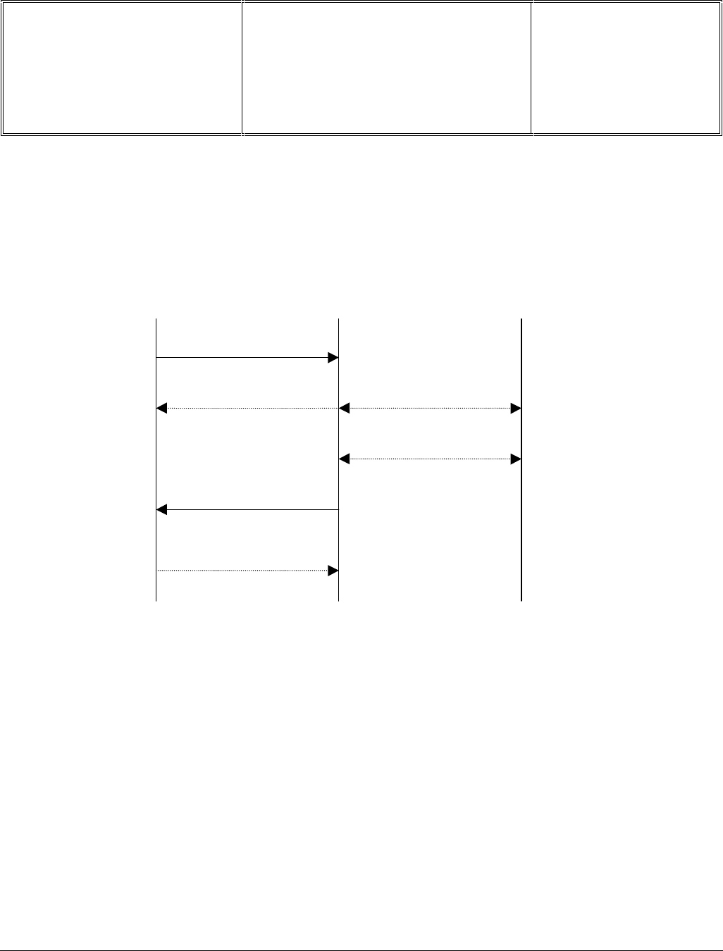
7.9.5 GPRS Attach and GPRS Detach procedures
The procedure for a GPRS attach is made by the MS to the SGSN. After Having executed a successful GPRS
attach, mobility management contexts are established in the MS and the SGSN, setting the MS in the READY
state. The MS is then able to activate PDP-contexts. The procedure of GPRS attach is illustrated below.
GPRS attach procedure
1. The MS sends a GPRS attach request which includes the GPRS mobile class and the multislot class.
2. Authentication is carried out in the same manner as with GSM, but instead of the MSC, it’s the SGSN that
sends the IMSI of the MS to the HLR, initiating the encryption algorithm.
3. A location update procedure stores the current SGSN of the MS in the HLR.
4. The attach accept response assigns a Temporary Logical Link Identity (TLLI) to the MS.
5. A GPRS attach complete response from the MS to the SGSN confirms the attach.
After the authentication within the GPRS attach procedure, no additional authentication is required during the entire
GPRS-session. A GPRS detach will terminate the ongoing GPRS-session. This detach could be initiated explicitly
by the MS or the SGSN, or implicitly when the STANDBY-timer runs out.
1. Attach Request
3. Location Update
2. Authentication
4. Attach Accept
Response
5. Attach Complete
MS SGSN HLR
Départ. Technical support- CM640 PROCEDURE COMPANY RESTRICTED
PHILIPS Consumer
Communications
Centre du Mans
Service Repair Support VY-V-640-82x
Page : 22 of 71
Langue : EN
Date : 25/02/03
PHILIPS ELECTRONICS N.V. 1999 VY-V-640-82x
All rights reserved. Reproduction in whole
or in part is prohibited without the written
consent of the copyright owner.
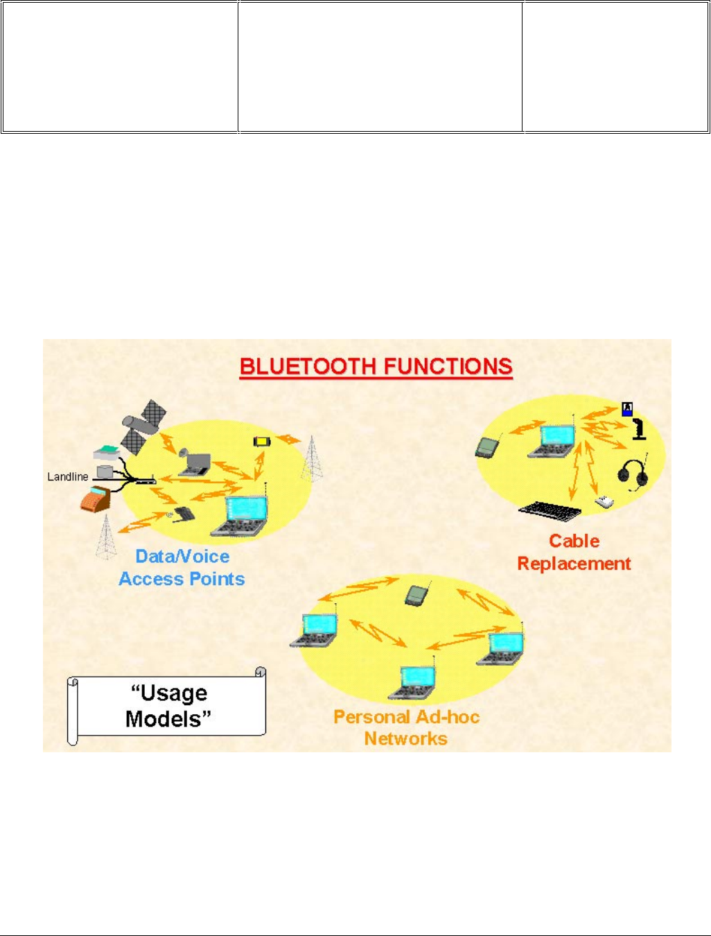
7.10 BLUETOOTH Introduction
7.10.1 Presentation
The Bluetooth technology eliminates the need for wires, cables and the corresponding connectors between
cordless or mobile phones, modems, headsets, PDAs, computers, printers, projectors, and so on and paves the
way for new and completely different devices and applications.
The majority of radio systems in commercial use today are based on a cellular radio Architecture. A mobile network
established on a wired backbone infrastructure uses one or more base stations placed at strategic positions to
provide local cell coverage; users apply portable phones, or more generic mobile terminals, to access the mobile
network; the terminals maintain a connection to the network via a radio link to the base stations. There is a strict
separation between the base stations and the terminals. Once registered to the network, the terminals remain
locked to the control channels in the network, and connections can be established and released according to the
control channel protocols. Channel access, channel allocation, traffic control, and interference minimization are
neatly controlled by the base stations.
Départ. Technical support- CM640 PROCEDURE COMPANY RESTRICTED
PHILIPS Consumer
Communications
Centre du Mans
Service Repair Support VY-V-640-82x
Page : 23 of 71
Langue : EN
Date : 25/02/03
PHILIPS ELECTRONICS N.V. 1999 VY-V-640-82x
All rights reserved. Reproduction in whole
or in part is prohibited without the written
consent of the copyright owner.
In contrast, in truly ad hoc systems, there is no difference between radio units; that is, there are no distinctive base
stations or terminals. Ad hoc connectivity is based on peer communications. There is no wired infrastructure to
support connectivity between portable units; there is no central controller for the units to rely on for making
interconnections, nor is there support for coordination of communications. In additions, there is no intervention of
operators. For scenarios envisioned by bluetooth, it is likely that a large number of ad hoc connections will coexist
in the same area without any mutual coordination; that is, tens of ad hoc links must share the same medium at the
same location in an uncoordinated fashion.
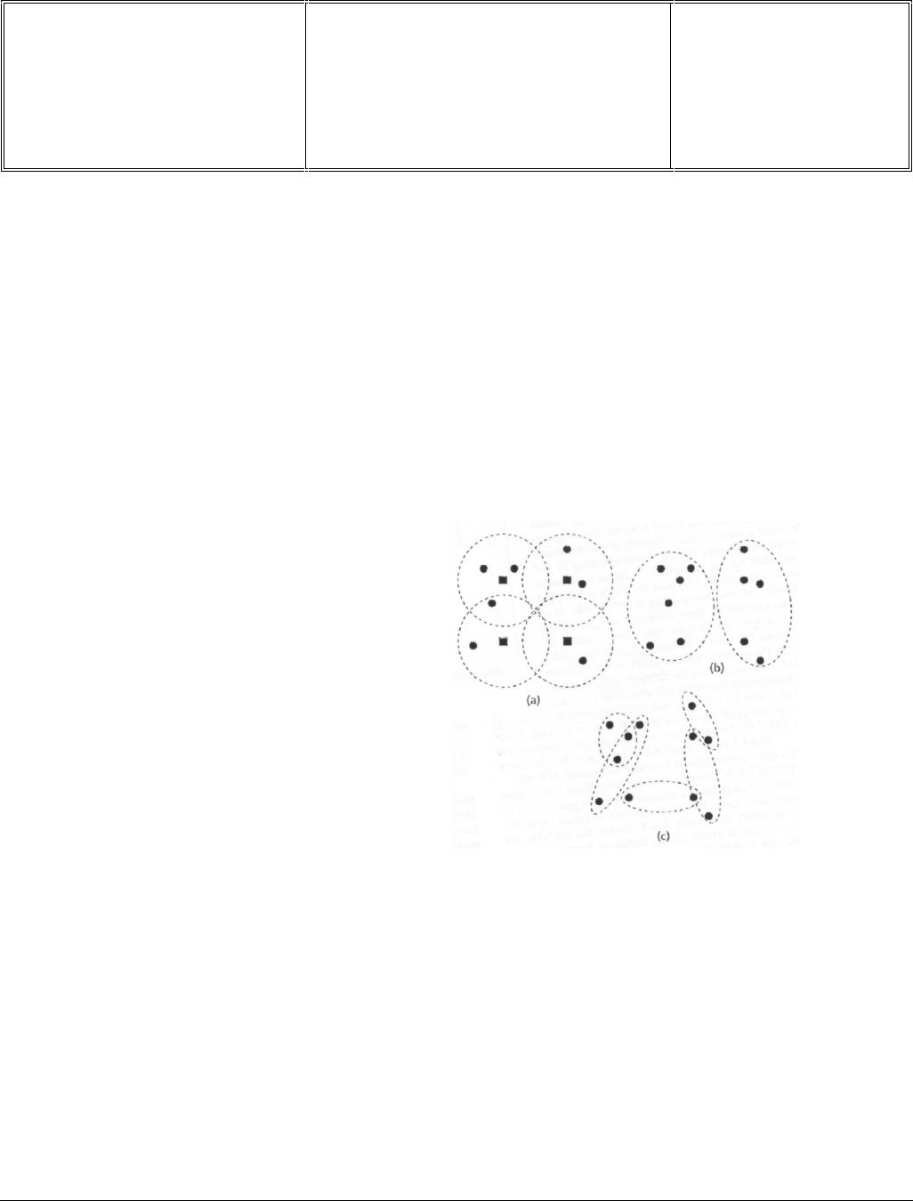
For bluetooth application typically many independent network overlap in the same area. This is called a scatter ad
hoc environment. Scatter ad hoc environments consist of a multiple networks, each containing only a limited
number of units. The difference between a conventional cellular environment, a conventional ad hoc environment,
and a scatter ad hoc environment is illustrated below :
Ad hoc radio system have been in use for some time, for example, walky talky systems used by the military, police
fire departments and rescue teams in general. However, the Bluetooth systems is the first commercial ad hoc radio
system envisioned to be used on a large scale and widely available to the public
Topologies for: a) cellular radio systems with
squares representing stationary base stations;
b) conventional ad hoc systems; and c) scatter
ad hoc systems.

Départ. Technical support- CM640 PROCEDURE COMPANY RESTRICTED
PHILIPS Consumer
Communications
Centre du Mans
Service Repair Support VY-V-640-82x
Page : 24 of 71
Langue : EN
Date : 25/02/03
PHILIPS ELECTRONICS N.V. 1999 VY-V-640-82x
All rights reserved. Reproduction in whole
or in part is prohibited without the written
consent of the copyright owner.
7.10.2 Networking
• Two or more units sharing the same channel form a PICONET
• One unit acts as the MASTER, the others act as SLAVES. Up to seven Slaves can be active on a Piconet
• Up to 200+ more slaves can remain locked to the master in a PARKED state.
• Each Piconet can only have one master but slaves can participate in different Piconets on a Time Division
Multiplex (TDM) basis.
• A Master in one Piconet can be a Slave in another
master
slave 1
slave 2
slave 3 master
slave 4 slave 5
master
slave 1
slave 2
slave 3
PICONETS
• Master can connect to 7 simultaneous or 200+ active slaves per
piconet
• Each piconet has maximum capacity (1 MSPS)
• Unique hopping pattern/ID for each piconet
SCATTERNETS
• Multiple Piconets with overlapping coverage
form a SCATTERNET
• High capacity
• Radios can share piconets!
Départ. Technical support- CM640 PROCEDURE COMPANY RESTRICTED
PHILIPS Consumer
Communications
Centre du Mans
Service Repair Support VY-V-640-82x
Page : 25 of 71
Langue : EN
Date : 25/02/03
PHILIPS ELECTRONICS N.V. 1999 VY-V-640-82x
All rights reserved. Reproduction in whole
or in part is prohibited without the written
consent of the copyright owner.
7.10.3 Bluetooth air interface parameters
Keys parameters
Frequency Band : 2.4GHz ISM Open band
Channel Spacing : 1MHz
RF bandwidth : 220kHz(-3dB), 1MHz(-20dBm)
Number of Channels : 79 or 23
(Depend on the country arrangement )
Modulation : GFSK
Communication method: TDD
Frequency Hopping : 1600 hops/s (625 msec)
Peak data rate : <1Mbit/sec
Maximum output power : 100mW (20dBm)
(Depend on power class)
Sensitivity : -70 dBm @ BER=1/1000
Frequency Band and RF Channels
Power Classes
Country
Country Frequency Range
Frequency Range RF Channels
RF Channels
Europe & USA
Japan
Spain
France
2400 - 2483.5MHz
2471 - 2497MHz
2445 - 2475MHz
2446.5 -2483.5MHz
F=2402 + k MHz
F=2473 + k MHz
F=2449 + k MHz
F=2454 + k MHz
k = 0 to 78
k = 0 to 22
k = 0 to 22
k = 0 to 22
Power
Class
Power
Class Maximum
Output Power
Maximum
Output Power
1
2
3
Nominal
Output Power
Nominal
Output Power Minimum
Output Power 1)
Minimum
Output Power 1) Power Control
Power Control
100 mW (20 dBm)
2.5 mW (4 dBm)
1 mW (0 dBm)
N/A
1mW (0 dBm)
N/A
1 mW (0 dBm)
0.25 mW (-6 dBm)
N/A
4 to +20 dBm
-302) to 0 dBm,
optional
-302) to 0 dBm,
optional
-302) to 0 dBm,
optional
Note 1: Minimum output power at maximum power setting.
Note 2: The lower range limit of -30 dBm is not mandatory and may be chosen
according to application needs.
Départ. Technical support- CM640 PROCEDURE COMPANY RESTRICTED
PHILIPS Consumer
Communications
Centre du Mans
Service Repair Support VY-V-640-82x
Page : 26 of 71
Langue : EN
Date : 25/02/03
PHILIPS ELECTRONICS N.V. 1999 VY-V-640-82x
All rights reserved. Reproduction in whole
or in part is prohibited without the written
consent of the copyright owner.
Modulation and Bit Rate
Radio Frequency Tolerance
The transmitted initial center frequency accuracy must be +/-75 kHz from FC.
The initial frequency accuracy is defined as being the frequency accuracy before any information is transmitted.
Note that the frequency drift requirement is not included in the +/-75 kHz.
Physical Links
Two link types Synchronous Connection - Oriented (SCO) link
Asynchronous Connection - Less (ACL) link
SCO : A point-to-point link between a master and a single slave in the piconet .
ACL : A point-to-multipoint link between the master and all the staves participating on the piconet.
Symbol Rate : 1Ms/s +/-20ppm
GFSK (Gaussian Frequency Shift Keying) with a BT=0.5
Binary One : Positive frequency deviation
Binary Zero : Negative frequency deviation
❖Maximum frequency deviation
: shall be between
140kHz and 175kHz
(greater than 115kHz)
Type of Packet
Type of Packet
One slot package
Three slot package
Five slot package
Maximum drift rate 1)
Frequency Drift
Frequency Drift
+/- 25 kHz
+/- 40 kHz
+/- 40 kHz
400 Hz/µs
Note 1 : The maximum drift rate is allowed anywhere in a packet.

Départ. Technical support- CM640 PROCEDURE COMPANY RESTRICTED
PHILIPS Consumer
Communications
Centre du Mans
Service Repair Support VY-V-640-82x
Page : 27 of 71
Langue : EN
Date : 25/02/03
PHILIPS ELECTRONICS N.V. 1999 VY-V-640-82x
All rights reserved. Reproduction in whole
or in part is prohibited without the written
consent of the copyright owner.
Rx parameters
- SENSITIVITY : -70 dBm @ BER=1/1000
- INTERFERENCE PERFORMANCE:
Requirement Ratio
Co-channel interference11 dB
Adjacent(1MHz) interfer. 0 dB
Image frequency interf. -9 dB
- OUT-OF-BAND BLOCKING PERFORMANCE
Interfering Signal Frequency Interfering Power
30 MHz - 2000 MHz -10 dBm
2000 MHz - 2400 MHz -27 dBm
2400 MHz - 2500 MHz -27 dBm
3000 MHz - 12.75 GHz -10 dBm
Départ. Technical support- CM640 PROCEDURE COMPANY RESTRICTED
PHILIPS Consumer
Communications
Centre du Mans
Service Repair Support VY-V-640-82x
Page : 28 of 71
Langue : EN
Date : 25/02/03
PHILIPS ELECTRONICS N.V. 1999 VY-V-640-82x
All rights reserved. Reproduction in whole
or in part is prohibited without the written
consent of the copyright owner.
7.10.4 Bluetooth communications
Packet format
Access code (72 bits)
This area supports the identification and synchronization of Bluetooth instruments. A typical 1010 pattern is sent as
4-bit preamble at the beginning. A measuring instrument must be able to accurately measure the frequency
deviation of the DUT within 4µs.
Header (54 bits)
This area of the packet contains organization information important for the call : the current address of the called
partner into the pico network, packet types used and also flow control and handshake information.
Payload (0 to 2744 bits)
Packet area of variable length where payload data is normally transmitted. The maximum length of the payload is
defined so that at least 220µs are available between the end of the payload and the change of the timeslot for the
synthesizer of the Bluetooth signal to settle to the next frequency channel.
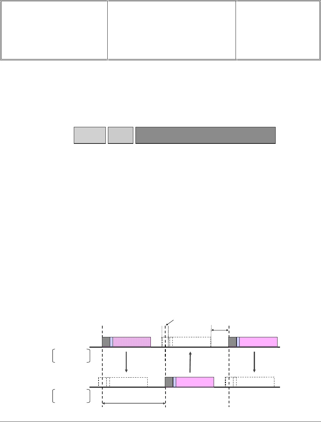
Frequency hopping and time multiplex
A Bluetooth subscriber always operates alternately as transmitter or receiver within a timeslot.
Access
code packet
header payload
72 54 0-2745
RF hop frequency : f(k) f(k +1) f(k +2)
Master
Slave
625 µsec
+/-10 µsec 220
µsec
even-numbered
time slot only
odd-numbered
time slot only
Départ. Technical support- CM640 PROCEDURE COMPANY RESTRICTED
PHILIPS Consumer
Communications
Centre du Mans
Service Repair Support VY-V-640-82x
Page : 29 of 71
Langue : EN
Date : 25/02/03
PHILIPS ELECTRONICS N.V. 1999 VY-V-640-82x
All rights reserved. Reproduction in whole
or in part is prohibited without the written
consent of the copyright owner.
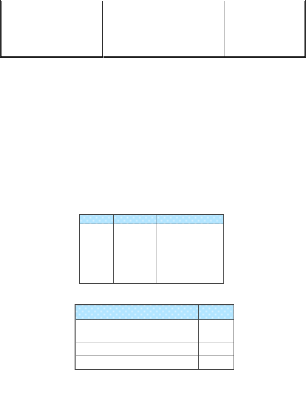
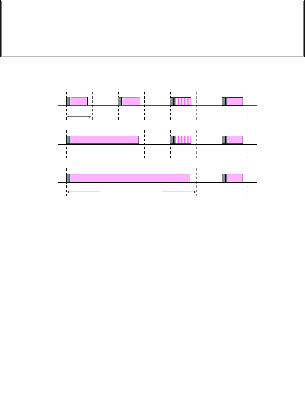
Multi-Slot Packets
Variable packet length for current packet type. Packets formats with different error correction are used depending
on the application
f(k) f(k +1) f(k +2) f(k +3) f(k +4) f(k +5) f(k +6)
f(k)
f(k) f(k +5) f(k +6)
f(k +3) f(k +4) f(k +5) f(k +6)
625 µsec
Burst Length 625 x 5 bit MAX

Départ. Technical support- CM640 PROCEDURE COMPANY RESTRICTED
PHILIPS Consumer
Communications
Centre du Mans
Service Repair Support VY-V-640-82x
Page : 30 of 71
Langue : EN
Date : 25/02/03
PHILIPS ELECTRONICS N.V. 1999 VY-V-640-82x
All rights reserved. Reproduction in whole
or in part is prohibited without the written
consent of the copyright owner.
7.11 E-MAIL Introduction
7.11.1 Presentation
Philips Fisio 820 & Fisio 825 feature an e-mail application allowing you to send and receive e-mails. It is same
functions with the e-mail used on PC. It is very similar. You can receive, retrieve or send email (text) and with
picture attachment (the maximum mail size is 10Kb)
E-mails can then be forwarded to someone else and attachments stored in your mobile phone.
This feature is subscription-dependent and specific Internet Service Providers (ISP) : your mobile phone readily
supports them if they are included in your subscription.
Philips Fisio820 supports 2 sets of E-mail addresses parameters. Mailboxes 1 and 2 feature the same settings
and options. Configuring them differently will allow you to have two different E-mail accesses/addresses from your
mobile. Thus you can have one private address and one for business purpose for example.
7.11.2 Protocols / Network
Protocols :
Philips Fisio820 & Fisio 825 have an Email application that supports POP3 (for receiving email) and SMTP
protocols (for sending) to access Internet E-mail servers supporting these protocols. POP3 and SMTP are widely
supported by Internet Service Providers and Intranet companies.
Network :
You use E-mail with GSM or GPRS networks. So you must configure the GSM or/and GPRS access
networks setting like W@p configuration.

Départ. Technical support- CM640 PROCEDURE COMPANY RESTRICTED
PHILIPS Consumer
Communications
Centre du Mans
Service Repair Support VY-V-640-82x
Page : 31 of 71
Langue : EN
Date : 25/02/03
PHILIPS ELECTRONICS N.V. 1999 VY-V-640-82x
All rights reserved. Reproduction in whole
or in part is prohibited without the written
consent of the copyright owner.
8.0 TEST PROCEDURES
8.1 Initial Functional Check for Fisio 820 & Fisio 825
Before to start the test procedure check the appearance of the humidity sticker located at the back of the phone.
Refer to CASES OUT OF WARRANTY GSM document to identify if the product is in/out of warranty.
8.1.1 Insert the Test Production Card into the SIM Reader at the back of the cellular phone and clip a charged
battery on the phone.
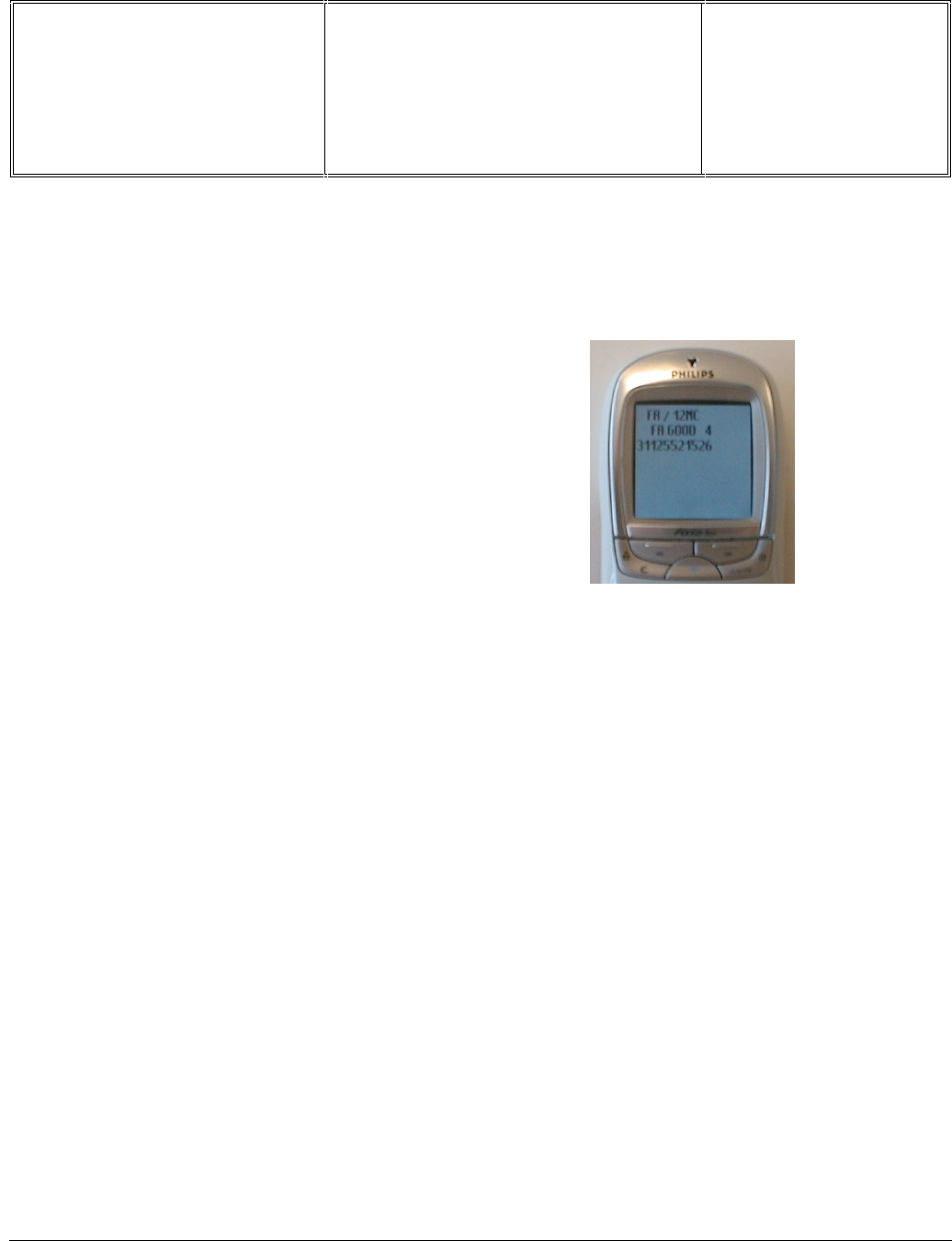
8.1.2 Press the «ON» button for 2 seconds at least and the LCD will show a message which contains information
of FA (Final Adjustment) status and 12NC.
8.1.3 Follow the instructions as mentioned below :
Step Procedure Observation
1
Press Key 1
Press Key 1 again.
Continue Buzzer signal
MANUAL
Left corner displays 00 AUTOTEST
00 KBD EEPROM
2
Press key 2
(Audio loop local effect)
Press key 2 again
"LocalEffect"
" XX XX XX“
“ XX XX” MANUAL
Left corner displays 01 AUTOTEST
00 KBD EEPROM
3
Press key 3
Audio loop test (Speak to Mic
and listen echo from Speaker)
Press key 3 again
"AUDIO EEP"
" xx xx xx xx ”
" xx xx xxxx ”
MANUAL
Left corner displays 02 AUTOTEST
00 KBD EEPROM
4
Press key 4
Press key 4 again
"KEY WITHOUT TEST"
MANUAL
Left corner displays 03 AUTOTEST
00 KBD EEPROM
5 Press Key 5
(Checkerboard test)
Press Key 5 again
Checkerboard 1 pixel on
MANUAL
Left corner displays 04 AUTOTEST
00 KBD EEPROM

Départ. Technical support- CM640 PROCEDURE COMPANY RESTRICTED
PHILIPS Consumer
Communications
Centre du Mans
Service Repair Support VY-V-640-82x
Page : 32 of 71
Langue : EN
Date : 25/02/03
PHILIPS ELECTRONICS N.V. 1999 VY-V-640-82x
All rights reserved. Reproduction in whole
or in part is prohibited without the written
consent of the copyright owner.
6 Press Key 6
Press Key 6 again
Checkerboard 2 pixel on
MANUAL
Left corner displays 05 AUTOTEST
00 KBD EEPROM
7 Press Key 7
Press key 7 again
Checkerboard 3 pixel on
MANUAL
Left corner displays 06 AUTOTEST
00 KBD EEPROM
8
Press key 8 (Eeprom Status)
Press Key 8 again
"EEPROM STAT”
H-0000-30-00
H-0000-00-00
SimLk XXXXX (Sim lock Status)
MANUAL
Left corner displays 07 AUTOTEST
00 KBD EEPROM
9
Press Key 9 Product
information
Compare information with
label printed on back case
Press key 9 again
“PROD INFO”
“XXXXXXXXX” (PN Number)
“XXXXXXXX”
“XXXXXXXX”
VY made in Le Mans
SA made in Singapore
EO made in Shenzhen
MANUAL
Left corner displays 08 AUTOTEST
00 KBD EEPROM
10
Press key 0
Press key 0 again
“ADC MEASURES”
“XXXX XXXX”
“XXXX XXXX”
MANUAL
Left corner displays 09 AUTOTEST
00 KBD EEPROM
Départ. Technical support- CM640 PROCEDURE COMPANY RESTRICTED
PHILIPS Consumer
Communications
Centre du Mans
Service Repair Support VY-V-640-82x
Page : 33 of 71
Langue : EN
Date : 25/02/03
PHILIPS ELECTRONICS N.V. 1999 VY-V-640-82x
All rights reserved. Reproduction in whole
or in part is prohibited without the written
consent of the copyright owner.
11
Press * (IMEI Test)
Compare IMEI with label
printed on back case
Press * again
"IMEI TEST"
" XXXXXX 50 XXXXXX X"
06 made in Singapore
50 made in Le-Mans
69 made in China
MANUAL
Left corner displays 12 AUTOTEST
00 KBD EEPROM
12
Press # (FA Status)
Press # again
"FA/12NC”
FA GOOD (Must be good) X
XXXXXXXXXXX (12NC)
MANUAL
Left corner displays 13 AUTOTEST
00 KBD EEPROM
13
Press Key C
Press Key C again
"KEY WITHOUT TEST"
MANUAL
Left corner displays 18 AUTOTEST
00 KBD EEPROM
14 Press Key
(Melody Test) & vibrator
Press Key again
"MELODY TEST"
User Melody should be heard and vibrations
felt
MANUAL
Left corner displays 14 AUTOTEST
00 KBD EEPROM
15 Press Key
Press Key again
"KEY WITHOUT TEST"
MANUAL
Left corner displays 15 AUTOTEST
00 KBD EEPROM
16 Press Key
Press Key again
"MEMORY TEST"
" XXXXXXXXX "
" XXXX XXXX "
" RAM OK "
MANUAL
Left corner displays 16 AUTOTEST
00 KBD EEPROM
17
Press Key MENU
Press Key MENU again
" PAGE "
" SELECTION"
" XX "
MANUAL
Left corner displays 11 AUTOTEST
00 KBD EEPROM

Départ. Technical support- CM640 PROCEDURE COMPANY RESTRICTED
PHILIPS Consumer
Communications
Centre du Mans
Service Repair Support VY-V-640-82x
Page : 34 of 71
Langue : EN
Date : 25/02/03
PHILIPS ELECTRONICS N.V. 1999 VY-V-640-82x
All rights reserved. Reproduction in whole
or in part is prohibited without the written
consent of the copyright owner.
Advanced autotests (used generally for troubleshooting)
Press MENU key to display “PAGE SELECTION.”
PRESS Key "1" to change test page to "01", then press .
(default test page is 00)
Key Functional test Observation
7
ANTENNA TEST " ANTENNA TST"
" Tx Level 10" (use keys 2 & 8 to change level)
" CHANNEL 0055" (use keys 4 & 6 for channel
selection)
To switch DCS / GMS/ EGSM, press "C" key to toggle
8Rx Power Level Use to detect Receiving Channel and its power
level
0Hand Free Carkit test Use this with PHILIPS headset to test the
auxiliary test
#
Defenses Code Display shows
Defenses 02
Bloc. 02 TAT5
Block B5B401C0
Use this to read out software hang issues or
drop call or any issue relating to network as
well.
8.1.4 If any of these steps failed functional, please refer to Chapter 10.
8.1.5 Perform visual check on battery connectors, car kit connectors and casing. If corrosion or deform send to
NSC for repair.
8.1.1 If the product is good, it is considered as a NFF (No Fault Found) product.
All the NFF products must be directly returned to the customer.

Départ. Technical support- CM640 PROCEDURE COMPANY RESTRICTED
PHILIPS Consumer
Communications
Centre du Mans
Service Repair Support VY-V-640-82x
Page : 35 of 71
Langue : EN
Date : 25/02/03
PHILIPS ELECTRONICS N.V. 1999 VY-V-640-82x
All rights reserved. Reproduction in whole
or in part is prohibited without the written
consent of the copyright owner.
8.2 RF Test
8.2.1 The Test SIM Card “SP” must be inserted in t he phone before starting the tests.
8.2.2 Set the equipment as shown on the picture in chapter 6.2
8.2.3 Set RF losses as following (tested with antenna coupler):
8.2.4 The following operations must be done:
- Synchronization/Registration
- Call set up from the mobile
- Voice loopback ( to check the sound quality)
- Call release
- Call set up from tester
- Call release from tester
- GPRS attach those two operations have to be added when the radio tester
- GPRS detach allows it
8.2.5 The following parameters must be checked in TCH loop mode :
Emission parameters :
- Power level
- RMS phase error
- Peak phase error
- Frequency error
- Power ramping
- Timing Advance
Reception parameters :
- Rx level
- Rx quality
- BER (Byte Error Rate)
- FER (Frame Error Rate)
- BLER (Block Error Rate) (can be replaced by a BER test at -104dBm)
Generally the test sequences built inside the testers will be used to check the mobile. You must assess that the test
sequences limits comply with the standard specifications and defined test plan.
Channel RX TX Channel RX TX
900 MHz 63 6,0 6,4 1800 MHz 598 20,5 25,5
3 5,0 6,6 512 18,0 33,5
62 6,0 6,4 700 20,5 25,5
123 7,0 6,2 884 23,0 17,4

Départ. Technical support- CM640 PROCEDURE COMPANY RESTRICTED
PHILIPS Consumer
Communications
Centre du Mans
Service Repair Support VY-V-640-82x
Page : 36 of 71
Langue : EN
Date : 25/02/03
PHILIPS ELECTRONICS N.V. 1999 VY-V-640-82x
All rights reserved. Reproduction in whole
or in part is prohibited without the written
consent of the copyright owner.
8.2.6 Radio test plan
Find below all the measurements which have to be done by test sequences.
When using a wired test solution (via RF cable), don’t forget that it is mandatory to measure the power level
radiated by the antenna (powermeter recommended). It is the only way to ensure good contact between
antenna and main board.
This warning doesn’t apply when using an antenna coupler.
Synchronization/Registration To be checked
Call set up from the mobile To be checked
Voice loopback ( to check the sound quality) To be checked
Call release To be checked
Call set up from tester To be checked
Call release from tester To be checked
Dualband handover To be checked
GPRS attach To be checked
GPRS detach To be checked
Power level Measurements
Power level XXXX
RMS phase error X X X X
High level Peak phase error X X X X
Frequency error X X X X
Power ramping X X X X
Timing advance X X
Power level XXXX
RMS phase error
Mid level Peak phase error
Frequency error
Power ramping
Timing advance
Power level XXXX
RMS phase error
Low Level Peak phase error
Frequency error
Power ramping X X X X
Timing advance
RF Level Measurements
Rx level X X X X
Rx qual
BER (Byte Error Rate) XXXX
FER (Frame Error Rate)
Rx level X X X X
Rx qual X X X X
BER (Byte Error Rate) XXXX
FER (Frame Error Rate) XXXX
BER Measurements on 104 frames = 8200 bits minimum
* BLER tests on 200 blocs only
In case the Radio tester is not GPRS capable replace this test by a BER test at -104.0dBm
XX
RX measurements
-104.0 dBm
-102.0 dBm
-85.0 dBm
BLER*(Bloc Error Rate)
Low Mid
Low Mid High
GSM Channels
Low Mid High
TX measurements
GSM Channels
DCS Channels
Low Mid High
DCS Channels
High

Départ. Technical support- CM640 PROCEDURE COMPANY RESTRICTED
PHILIPS Consumer
Communications
Centre du Mans
Service Repair Support VY-V-640-82x
Page : 37 of 71
Langue : EN
Date : 25/02/03
PHILIPS ELECTRONICS N.V. 1999 VY-V-640-82x
All rights reserved. Reproduction in whole
or in part is prohibited without the written
consent of the copyright owner.
8.2.7 GSM Specification (900 Mhz)
Test parameter Channel Level Standard specifications
EMISSION
Phase Error RMS 1, 62, 124 5, 10, 15 0 to 5 degrees
Phase Error Peak 1, 62, 124 5, 10, 15 -20 to +20 degrees
Frequency Error 1, 62, 124 5, 10, 15 -90 Hz to +90 Hz
Power Ramping 1, 62, 124 5, 10, 15 Mask
Modulation 1, 62, 124 5, 10, 15 Mask
Switching Transients 1, 62, 124 5, 10, 15 Mask
Timing Advance 1, 62, 124 5, 10, 15 +/- 1.00 bit
Power Reading
Output Power Average 1, 62, 124 Level 19 5 +/- 5 dBm
1, 62, 124 Level 15 13 +/- 3 dBm
1, 62, 124 Level 10 23 +/- 2 dBm
1, 62, 124 Level 5 33 +/- 2 dBm
RECEPTION
Rx Level 1, 62, 124 -102 dBm 4 to 12
Rx Qual 0 to 1
Rx Level 1, 62, 124 -85 dBm 21 to 29
Rx Qual 0
Rx Level 1, 62, 124 -60 dBm 46 to 54
Rx Qual 0 to 0
TCH LOOP
SENSITIVITY
BER 1, 62, 124 -85 dBm 0%
FER 1, 62, 124 -85 dBm 0%
BER 1, 62, 124 -102 dBm < 2.44%
FER 1, 62, 124 -102 dBm 0%
If a phone is out of the specifications, it must be sent to the Repair Center.

Départ. Technical support- CM640 PROCEDURE COMPANY RESTRICTED
PHILIPS Consumer
Communications
Centre du Mans
Service Repair Support VY-V-640-82x
Page : 38 of 71
Langue : EN
Date : 25/02/03
PHILIPS ELECTRONICS N.V. 1999 VY-V-640-82x
All rights reserved. Reproduction in whole
or in part is prohibited without the written
consent of the copyright owner.
8.2.8 PCN Specification (1800 Mhz)
Test parameter Channel Level Standard specifications
ÉMISSION
Phase error RMS 512, 700, 885 0,5,10 0 to 5 degree
Phase error Peak 0,5,10 -20 to +20 degree
Frequency Error 0,5,10 -180 Hz to + 180 Hz
Power Ramping 0,5,10 Mask
Modulation 0,5,10 Mask
Switching Transients 0,5,10 Mask
Timing Advance 0,5,10 +/- 1.00 bit
Power reading
Output Power Level 0 30 +/- 2 dBm
Level 10 10 +/- 4.0 dBm
Level 15 0 +/- 5.0 dBm
RECEPTION
Rx Level 512, 700, 885 -102dbm 4 to 12
Rx Qual -102dbm 0 to 1
Rx Level 512, 700, 885 -85dbm 21 to 29
Rx Qual -85dbm 0
Rx Level 512, 700, 885 -60dbm 46 to 54
Rx Qual -60dbm 0
TCH LOOP
SENSITIVITY
BER 512, 700, 885 -85dbm 0%
FER 512, 700, 885 -85dbm 0%
BER 512, 700, 885 -102dbm 2.44%
FER 512, 700, 885 -102dbm 0%
If a phone is out of the specifications, it must be sent to the Repair Center.
Départ. Technical support- CM640 PROCEDURE COMPANY RESTRICTED
PHILIPS Consumer
Communications
Centre du Mans
Service Repair Support VY-V-640-82x
Page : 39 of 71
Langue : EN
Date : 25/02/03
PHILIPS ELECTRONICS N.V. 1999 VY-V-640-82x
All rights reserved. Reproduction in whole
or in part is prohibited without the written
consent of the copyright owner.
8.2.9 GPRS Specification (900Mhz & 1800 Mhz)
RADIO : GPRS part
Class 4 Class 10 Class 12 § GSM 11.10
Rx
Rx Levels idem GSM 900/1800 21.5
Rx Levels Linearity idem GSM 900/1800 21.5
Sensivity
BER/FER -85dBm
(8200 samples) idem GSM 900/1800 14.2.1
BER/FER -102dBm
(8200 samples) idem GSM 900/1800 14.2.1
BLER CS-1 (-104dBm) < 10% on 400blocs with 20 blocs errors 14.16
BLER CS-2 (-104dBm) < 10% on 400blocs with 20 blocs errors 14.16
BLER CS-3 (-104dBm) < 10% on 400blocs with 20 blocs errors 14.16
BLER CS-4 (-101dBm) < 10% on 400blocs with 20 blocs errors 14.16
Tx
Phase error RMS idem GSM 900/1800 on last timeslot 13.16.1
Phase error Peak idem GSM 900/1800 on last timeslot 13.16.1
Frequency error idem GSM 900/1800 on last timeslot 13.16.1
Output Power Levels GSM 900/1800 on all timeslot and conf. 13.16.2
Power Ramping GSM 900/1800 on all timeslot and conf. 13.16.2
If a phone is out of the specifications, it must be sent to the Repair Center.

Départ. Technical support- CM640 PROCEDURE COMPANY RESTRICTED
PHILIPS Consumer
Communications
Centre du Mans
Service Repair Support VY-V-640-82x
Page : 40 of 71
Langue : EN
Date : 25/02/03
PHILIPS ELECTRONICS N.V. 1999 VY-V-640-82x
All rights reserved. Reproduction in whole
or in part is prohibited without the written
consent of the copyright owner.
8.2.10 Bluetooth Specification (2,4Ghz)
Tx Bluetooth
Power Peak Ppk < 200 mW [23 dBm]
Power Average [Class 1] Pav > 1 mW [0dBm]
Power Average [Class 2] 0,25mW [-6dBm] < Pav < 2,5mW [4dBm]
Power Average [Class 3] Pav < 1 mW [0dBm]
Power Density PD < 100mW [20 dBm] per 100 kHz
Power Control 2 dBm ≤ Step Size ≤ 8 dBm
at minimum power step : Pav < 4 dBm [for Class 1]
Initial Carrier Frequency [Accuracy] ftx-75 kHz ≤ fo ≤ ftx+75 kHz
Carrier Frequency Drift One slot packet :20 kHz to 25 kHz
Three slot packet : 30 kHz to 40 kHz
Five slot packet : 30 kHz to 40 kHz
Maximum Drift Rate ≤ 400 Hz / µs
Modulation Characteristics [Deviation] +/-140kHz≤∆f1max≤+/-175kHz [11110000..-Bit pattern]
and 115kHz ≤ ∆f2max [101010…-Bit pattern]
and 0,8 ≤ ∆f2max / ∆f1avg
Départ. Technical support- CM640 PROCEDURE COMPANY RESTRICTED
PHILIPS Consumer
Communications
Centre du Mans
Service Repair Support VY-V-640-82x
Page : 41 of 71
Langue : EN
Date : 25/02/03
PHILIPS ELECTRONICS N.V. 1999 VY-V-640-82x
All rights reserved. Reproduction in whole
or in part is prohibited without the written
consent of the copyright owner.
8.3 Battery Charging (IGN : Ignition) / Current Consumption
8.3.1 Charger detection / Battery charging
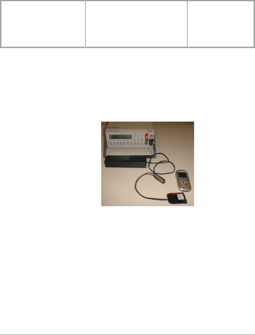
- Plug the transformer unit into an easily accessible AC power socket.
- Insert the Test production Card in the mobile, plug a dummy Battery with a multimeter added (see picture) for
current measurement.
- Plug the connector of the charger into the right socket at the base of the transceiver
The battery symbol should indicate the state of charge :
• Bars moving - means the battery is being charged.
• Steady - means the battery is fully charged.
If the battery is totally discharged, the battery icon will start scrolling 2 to 3 minutes only after being connected to
charger.
After few seconds a charge current of 200 < I (mA) < 600 have to be observed
- Unplug the charger
8.3.2 Current consumption
a) Check current_OFF :
When the mobile is OFF the current measured must be : 0.05 < I (mA) < 0.23
Départ. Technical support- CM640 PROCEDURE COMPANY RESTRICTED
PHILIPS Consumer
Communications
Centre du Mans
Service Repair Support VY-V-640-82x
Page : 42 of 71
Langue : EN
Date : 25/02/03
PHILIPS ELECTRONICS N.V. 1999 VY-V-640-82x
All rights reserved. Reproduction in whole
or in part is prohibited without the written
consent of the copyright owner.
b) Check Current_ON
- Turn the mobile on.
When the mobile is ON (backlight activated)
When the backlight goes down (after 15 sec approx.), the current measured must be : 15 < I (mA) < 19 for both
models
c) Check Current_maximum
- Press on OK to activate Page selection. Press the Key 1 and then OK to select Page 1
- Press on Key 7 to select Antenna test. Press on the Key 8 as much times as necessary to reach level 5. (The
mobile is now set at his maximum emission level)
When the mobile is emitting (backlight OFF) the current measured must be : 195 < I (mA) < 350
- Remove the battery.
- Gently slide the card out away from the Product
For Fisio 820 :
the current measured must be : 150 < I (mA) < 190
For Fisio 825 :
the current measured must be : 200 < I (mA) < 240
This measurement has to be operated during first seconds after switch on.
Départ. Technical support- CM640 PROCEDURE COMPANY RESTRICTED
PHILIPS Consumer
Communications
Centre du Mans
Service Repair Support VY-V-640-82x
Page : 43 of 71
Langue : EN
Date : 25/02/03
PHILIPS ELECTRONICS N.V. 1999 VY-V-640-82x
All rights reserved. Reproduction in whole
or in part is prohibited without the written
consent of the copyright owner.
8.4 W@P Test Procedure
With regard to the mobile phones only four things can prevent the W@P applications to operate properly :
• The Mobile Phone is not W@P able
• Registration problem (W@P & data/fax options should be needed depending on the operator)
• A bad configuration (wrong W@P parameters)
• The mobile has a deficient Radio part.
So that’s why to solve W@P problems the following process must be observed.
Ensure about the W@P capability of the mobile phone.
Interrogate the customer regarding his operator registration.
Check with the customer that all the needed parameters are stored in the phone memory
( a quick test has to be performed to check memory reliability)
Perform a functional and a radio test of the mobile phone.
The W@P Test procedure as to be performed only if the customer complains about W@P applications.
8.4.1 Functional and radio test
Before starting the W@P procedure it must be assumed that the functional test and the radio test have been done
successfully.
(Refer to chapters 8.1 & 8.2)
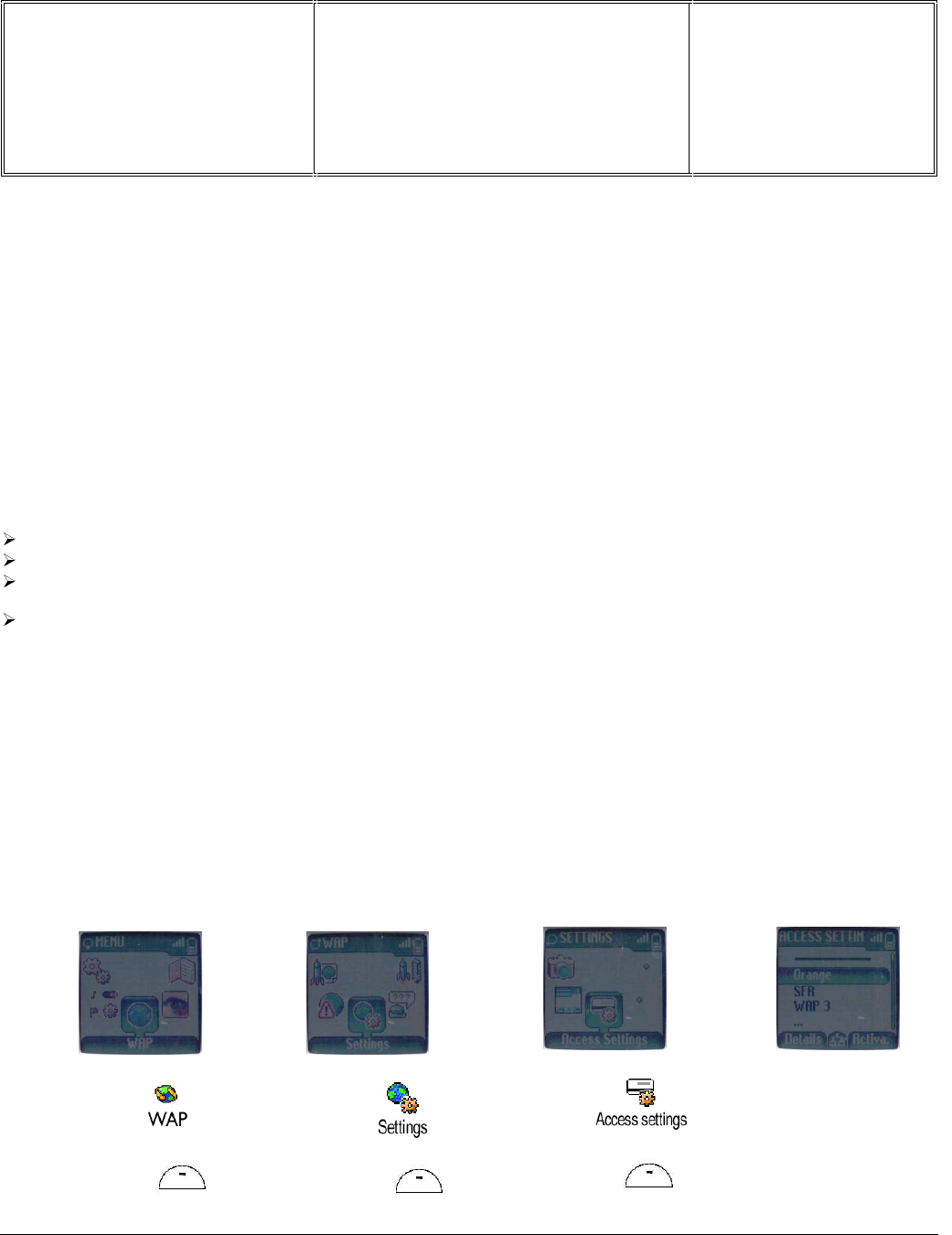
8.4.2 W@P parameters settings (to be checked using the Operator Simcard)
Press MENU
Select
and Press
Select
and press
Select
And press
The 3 available w@p
configurations are
displayed

Départ. Technical support- CM640 PROCEDURE COMPANY RESTRICTED
PHILIPS Consumer
Communications
Centre du Mans
Service Repair Support VY-V-640-82x
Page : 44 of 71
Langue : EN
Date : 25/02/03
PHILIPS ELECTRONICS N.V. 1999 VY-V-640-82x
All rights reserved. Reproduction in whole
or in part is prohibited without the written
consent of the copyright owner.
Select the w@p configuration you want to check and press Details and then press GSM Settings or GPRS Settings
to display wanted configuration. Ensure that the parameters are correct.
If the parameters are not the ones expected you may want to modify them. To do this, return to the Access Setting
menu by pressing on Key C as many time as necessary.
Three options are possible concerning w@p bearer :
Select the most suitable one according to your network subscription.
Otherwise from Change menu following parameters can be modified :
Home page parameter (URL):
This parameter is a string of characters (ASCII) used to identify the protocol (eg: HTTP), the location of the
server (eg: WAP.Philips.com), the port number (optional if = 80) and the access path
(eg:/glossair/glossair.htm).The end user can use the operator’s home page or set up another one in the mobile
phone. The URL can be set as follows:
and Press Select
and Press
Select
and Press
The network used to
bear the w@p
information can be
selected as following
and Press
Enter the home
address
and Press
Départ. Technical support- CM640 PROCEDURE COMPANY RESTRICTED
PHILIPS Consumer
Communications
Centre du Mans
Service Repair Support VY-V-640-82x
Page : 45 of 71
Langue : EN
Date : 25/02/03
PHILIPS ELECTRONICS N.V. 1999 VY-V-640-82x
All rights reserved. Reproduction in whole
or in part is prohibited without the written
consent of the copyright owner.
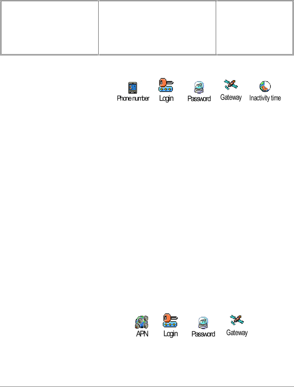
GSM Settings
GSM settings consist in many parameters :
Phone number parameter:
This parameter is the phone number required to perform a data transmission to the Internet Service
Provider (ISP) and given by the operator. ISP use either analogue or numeric interfaces to connect to the
subscriber. If the operator uses a digital interface but the phone number is set in the analogue area of the phone,
data connection will fail (and vice versa).
Login parameter:
This parameter is provided by the operator.
Password parameter:
This parameter is provided by the operator.
Gateway parameter (IP):
An IP address is used to recognize computers connected to a network. It is made up of 4 * 3 digits (8 bits) and
separated by points. Each computer has its own IP address. For W@P application, IP address is used to access the gateway.
This parameter is provided by the operator.
Inactivity time:
This parameters allows you to manage an inactivity time period after which the phone automatically ends
up the w@p session and returns to idle mode screen.
GPRS Settings
GPRS settings consist in many parameters :
APN Number:
This parameter sets the address of the external data network. You want to connect to, a text string or an IP
address used to establish the connection with your w@p service provider (ISP).

Départ. Technical support- CM640 PROCEDURE COMPANY RESTRICTED
PHILIPS Consumer
Communications
Centre du Mans
Service Repair Support VY-V-640-82x
Page : 46 of 71
Langue : EN
Date : 25/02/03
PHILIPS ELECTRONICS N.V. 1999 VY-V-640-82x
All rights reserved. Reproduction in whole
or in part is prohibited without the written
consent of the copyright owner.
8.4.3 W@P Application launch
The phone is now ready to access to the W@P Gateway. Please launch the W@P application to ensure it works
properly.
8.4.4 Memory reliability
After recording the W@P parameters :
Turn off the mobile
Remove the battery
Wait 5 seconds
Clip the battery again
Turn on the mobile
Check that the parameters still present.
Error message during w@p connections are mainly due to incorrect parameters. The operator should be
contacted before first use, in order to have the appropriate w@p and Gprs parameters.

Départ. Technical support- CM640 PROCEDURE COMPANY RESTRICTED
PHILIPS Consumer
Communications
Centre du Mans
Service Repair Support VY-V-640-82x
Page : 47 of 71
Langue : EN
Date : 25/02/03
PHILIPS ELECTRONICS N.V. 1999 VY-V-640-82x
All rights reserved. Reproduction in whole
or in part is prohibited without the written
consent of the copyright owner.
8.4.5 W@P Error messages
Error messages may be displayed on the mobile phone screen. Some of these are listed next:
Network not responding:This error message is displayed for various problems, such as:
Network cannot be reached (not enough reception bars).
Login and/or password are wrong.
Subscription does not allow W@P access
Server not responding: Could be due to: Bad IP address (gateway parameter).
Internet server is not enabled:
Could be due to: Bad IP address (gateway parameter).
Not acceptable: Could be due to: Bad home page address (URL)
An internal gateway error prevents the gateway from fulfilling your request:
Could be due to: Bad home page address (URL)
PROCEED http://phone.com
Could be due to: Bad home page address (URL)
Error content exit size XXXX bytes:
Could be due to: Too much data are coming to the phone.
Operator dependent.
Try later: Could be due to: Network cannot be reached (not enough
reception bars).
Busy network.
Bitmap error: Could be due to: The content is not W@P; the image can not
be displayed.
Note: The phone can not be switched off with ON/OFF key when W@P application is used. It has not to be
considered as a bug.

Départ. Technical support- CM640 PROCEDURE COMPANY RESTRICTED
PHILIPS Consumer
Communications
Centre du Mans
Service Repair Support VY-V-640-82x
Page : 48 of 71
Langue : EN
Date : 25/02/03
PHILIPS ELECTRONICS N.V. 1999 VY-V-640-82x
All rights reserved. Reproduction in whole
or in part is prohibited without the written
consent of the copyright owner.
8.4.6 W@P Exchange criteria
Exchanges for W@P problems should be extremely rare because the chances of having a defective
mobile phone is small compared to the misuse of the customers. W@P is a software application and must be
considered as such. From a hardware point of view, the Flash memory may have to be changed if W@P
parameters cannot be saved but the probability of encountering this problem is near to zero.
The mobile phone has to be considered as a defective one only if the memory test or the functional & radio
tests are wrong.
The points which have to be checked carefully with the customers are listed next:
* W@P parameters (phone not W@P locked) These parameters are very critical. If a letter, a sign or a number
is wrong, W@P connection will fail.
* Covered area The end user should access W@P services with only 1 reception bar. In practice, it is assumed
that more than 2 bars are required. For testing purpose, the help desk/ASC/NSC operator will have to ask the end
user to test the phone in a well covered area (minimum of 3 bars).
* WAP phone A WAP phone is mandatory in order to access W@P services. However, the
subscription is operator dependent.
* Call barring Call barring has to be cancelled (menu: outgoing/data calls)
* Hourglass icon If the end user can see the transmitting icon (after the hourglass icon) on the mobile
phone, it means Internet access was successful. Hence, the mobile phone is working correctly.
* Roaming If the end user is in a foreign country, he may not be able to use the W@P feature or may have to
change the W@P parameters (for example, use the analogue number instead of the ISDN one). The customer has
to contact his/her operator for further information.
* Number of attempts W@P services may be accessed after several attempts depending on the covered area or
the network status (busy). Obviously, this is not a case for exchange and the help desk/ASC/NSC operator will
have to make sure that the end user has tried several times before diagnosing the problem.
* Impossible to display W@P pages A W@P page may be displayed on the mobile phone screen of a competitor
and not by the Philips transceiver. The help desk /ASC/NSC operator will have to explain that the W@P navigators
are different. Sometimes, contents of particular pages can be decoded by a navigator and not by another (idem for
Netscape and Internet Explorer).

Départ. Technical support- CM640 PROCEDURE COMPANY RESTRICTED
PHILIPS Consumer
Communications
Centre du Mans
Service Repair Support VY-V-640-82x
Page : 49 of 71
Langue : EN
Date : 25/02/03
PHILIPS ELECTRONICS N.V. 1999 VY-V-640-82x
All rights reserved. Reproduction in whole
or in part is prohibited without the written
consent of the copyright owner.
8.5 Bluetooth Test Procedure
In order to communicate with different wireless device you will be using, Bluetooth feature of your mobile phone
must be set in stand-by mode.
Press and select Settings, BT Settings, Bluetooth On/OFF and press .
Press or to change the duration time to 15 min. Then press to confirm.
Bluetooth devices must first be paired to each other (e.g. the headset to your mobile phone) before being use.
Ensure that both the mobile phone and the headset are on and place then near each other (refer to the headset
documentation for information on pairing).
Press on your mobile phone and select Accessories, BT Headset, Detect. Ensure that the
headset is set in pairing mode (refer to the headset documentation) an press on your mobile phone.
An animated icon appears on the screen, showing that your mobile is searching the headset. During pairing it is
recommended that the mobile phone and the device you are using it with are no more than 1m./ 3ft. Apart, with no
solid objects in between.
Pairing authentification should take place within 1 min.
Select in the list of detected devices the headset to be authentified and paired and press .
Enter the pairing code supplied with your headset, then press .
A pairing code (16 characters max.) , allows the mobile to identify and differentiate several devices from one
another. The default paring code is usually 0000.
Once the mobile has found the headset, it displays its name and address. Press to store this information :
your headset is ready for use with your mobile phone.
To fulfill the test procedure make a call using the bluetooth headset.
Your mobile phone will NOT answer the Bluetooth connection requests of wireless devices if the stand-by
duration time is set to "Never".
To turn Bluetooth Off is recommended when not using it, as it increases energy consumption.
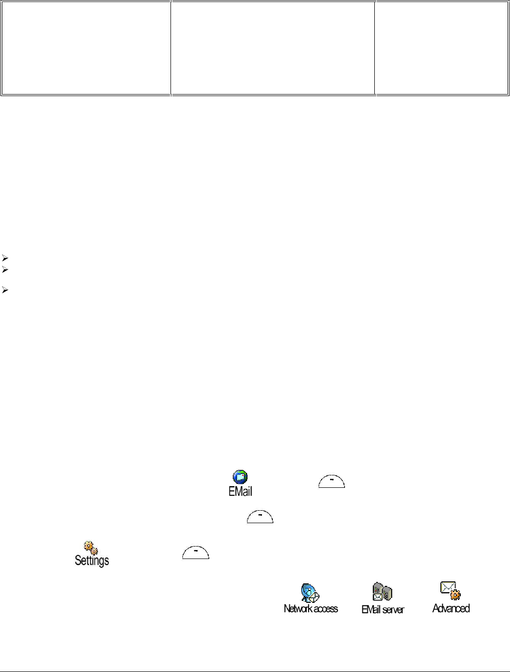
Départ. Technical support- CM640 PROCEDURE COMPANY RESTRICTED
PHILIPS Consumer
Communications
Centre du Mans
Service Repair Support VY-V-640-82x
Page : 50 of 71
Langue : EN
Date : 25/02/03
PHILIPS ELECTRONICS N.V. 1999 VY-V-640-82x
All rights reserved. Reproduction in whole
or in part is prohibited without the written
consent of the copyright owner.
8.6 E-MAIL Test Procedure
With regard to the mobile phones only two things can prevent the W@P applications to operate properly :
• A bad configuration (wrong E-mail parameters)
• The mobile has a deficient Radio part.
So that’s why to solve E-mails problems the following process must be observed.
Interrogate the customer regarding his Internet subscription and his Internet Service Provider.
Check with the customer that all the needed parameters are stored in the phone memory
( a quick test has to be performed to check memory reliability)
Perform a functional and a radio test of the mobile phone.
The E-mail Test procedure as to be performed only if the customer complains about E-mail applications.
8.6.1 Functional and radio test
Before starting the E-mail procedure it must be assumed that the functional test and the radio test have been done
successfully.
(Refer to chapters 8.1 & 8.2)
8.6.2 E-mail parameters settings (to be checked using the Operator Simcard)
First Press MENU key and select the E-mail icon and press .
Select a mailbox (Mailbox 1 for example) and press .
Select Settings and press . It will display 3 settings groups :
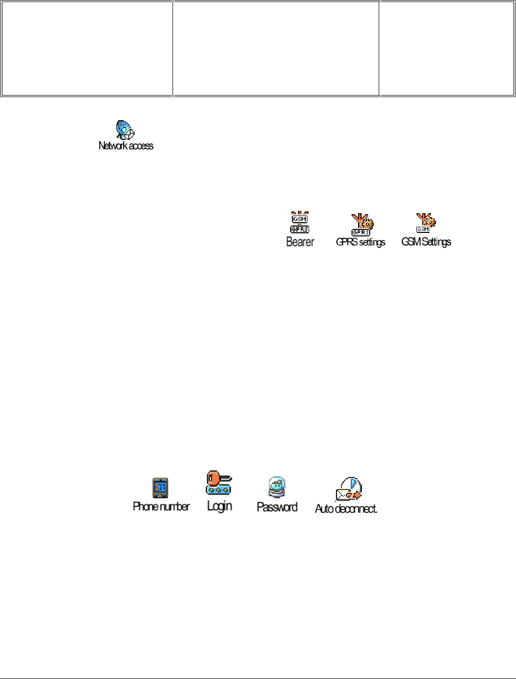
Départ. Technical support- CM640 PROCEDURE COMPANY RESTRICTED
PHILIPS Consumer
Communications
Centre du Mans
Service Repair Support VY-V-640-82x
Page : 51 of 71
Langue : EN
Date : 25/02/03
PHILIPS ELECTRONICS N.V. 1999 VY-V-640-82x
All rights reserved. Reproduction in whole
or in part is prohibited without the written
consent of the copyright owner.
Network Access
All this parameters contained in this menu are operator and/or subscription dependent.
From this menu following parameters have to be set :
Bearer
Allows you to select the type of network used when launching a connection to the e-mail server.
• GSM
Your mobile will only use the GSM network for e-mail connections.
• GPRS
Your mobile will only use the GPRS network for e-mail connections.
• GPRS first
Your mobile will first try to connect to the GPRS network, then to the GSM network if the GPRS network isn’t
available when launching an e-mail connection.
GSM settings
The GSM settings menu includes the following parameters which have to be checked
It is the same configuration as Wap GSM Settings. (See Chapter 8.4.2 ) :
• Auto disconnection
Allows you to select an inactivity time period after which the phone automatically disconnects (if a connection was
is progress) from the network.
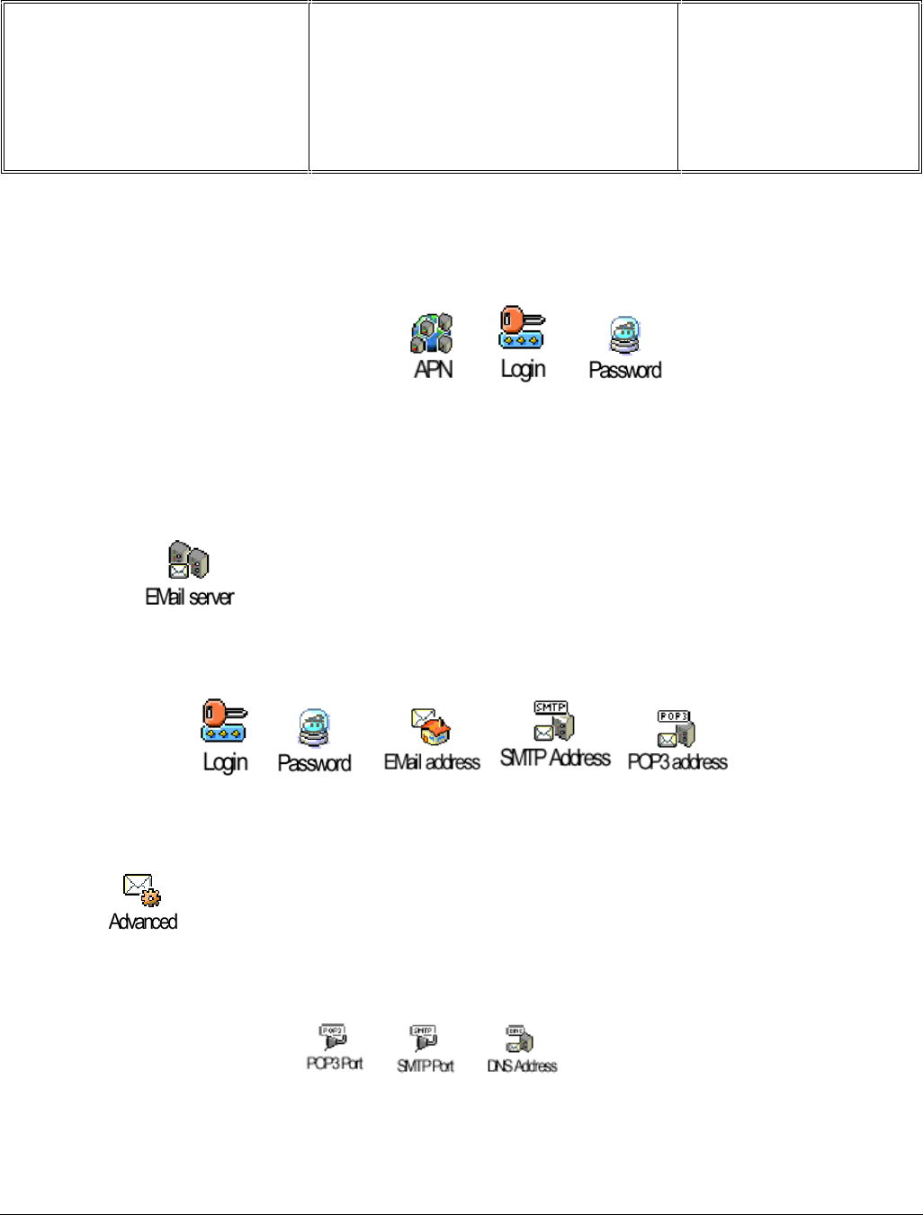
Départ. Technical support- CM640 PROCEDURE COMPANY RESTRICTED
PHILIPS Consumer
Communications
Centre du Mans
Service Repair Support VY-V-640-82x
Page : 52 of 71
Langue : EN
Date : 25/02/03
PHILIPS ELECTRONICS N.V. 1999 VY-V-640-82x
All rights reserved. Reproduction in whole
or in part is prohibited without the written
consent of the copyright owner.
GPRS settings
The GSM settings menu includes the following parameters which have to be checked
It is the same configuration as Wap GPRS Settings. (See Chapter 8.4.2) :
E-mail server
The E-mail server menu includes the following parameters which have to be checked
All these parameters have to be provided by the Internet Service Provider.
Advanced
The Advanced menu includes the following parameters which have to be checked
All these parameters have to be provided by the Internet Service Provider.

Départ. Technical support- CM640 PROCEDURE COMPANY RESTRICTED
PHILIPS Consumer
Communications
Centre du Mans
Service Repair Support VY-V-640-82x
Page : 53 of 71
Langue : EN
Date : 25/02/03
PHILIPS ELECTRONICS N.V. 1999 VY-V-640-82x
All rights reserved. Reproduction in whole
or in part is prohibited without the written
consent of the copyright owner.
8.6.3 E-mail sending/receiving verification
Once all the parameters mentioned in the previous chapter have been checked. The mobile phone is ready to
send/receive E-mails.
Check this by sending an E-mail from the mobile phone and checking the destination mailbox from a computer.
Or send an E-mail from a computer and check your mailbox from the mobile phone.
8.6.4 Memory reliability
After recording the E-mail parameters :
Turn off the mobile
Remove the battery
Wait 5 seconds
Clip the battery again
Turn on the mobile
Check that the parameters still present.
8.6.5 E-mail Error messages
Error messages may be displayed on the mobile phone screen. Some of these are listed in Chapter 8.4.5 W@P
Error Message
8.6.6 E-mail Exchange criteria
Exchanges for E-mail problems should be extremely rare because the chances of having a defective mobile
phone is small compared to the misuse of the customers.
Error messages during connections are mainly due to incorrect parameters: you should contact your GSM
operator and your Internet Service Provider before first use, in order to have the appropriate GSM/GPRS
parameters and mailbox parameters.
The mobile phone has to be considered as a defective one only if the memory test or the functional & radio
tests are wrong
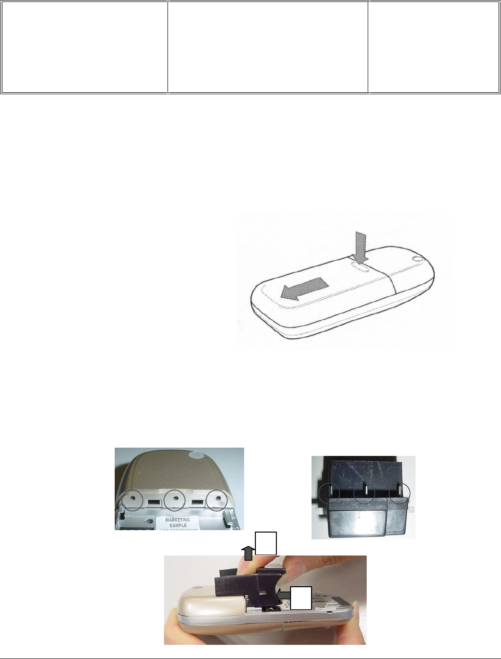
Départ. Technical support- CM640 PROCEDURE COMPANY RESTRICTED
PHILIPS Consumer
Communications
Centre du Mans
Service Repair Support VY-V-640-82x
Page : 54 of 71
Langue : EN
Date : 25/02/03
PHILIPS ELECTRONICS N.V. 1999 VY-V-640-82x
All rights reserved. Reproduction in whole
or in part is prohibited without the written
consent of the copyright owner.
9.0 ASSEMBLY / DISMANTLEMENT PROCEDURES
9.1 Dismantlement
9.1.1 Take the product, remove the battery.
9.1.2 Remove the Antenna Ass’y
The antenna cabinet needs to be removed first in order to reveal two of the four screws, which secure the rear
chassis.
Insert the three pins of the antenna cab removal tool into the three holes of the antenna cab. Press the tool against
antenna cab until the catches are released, then lift antenna cab away from transceiver.
Press below the rubber (Philips logo)
and slide the battery downwards
1
2
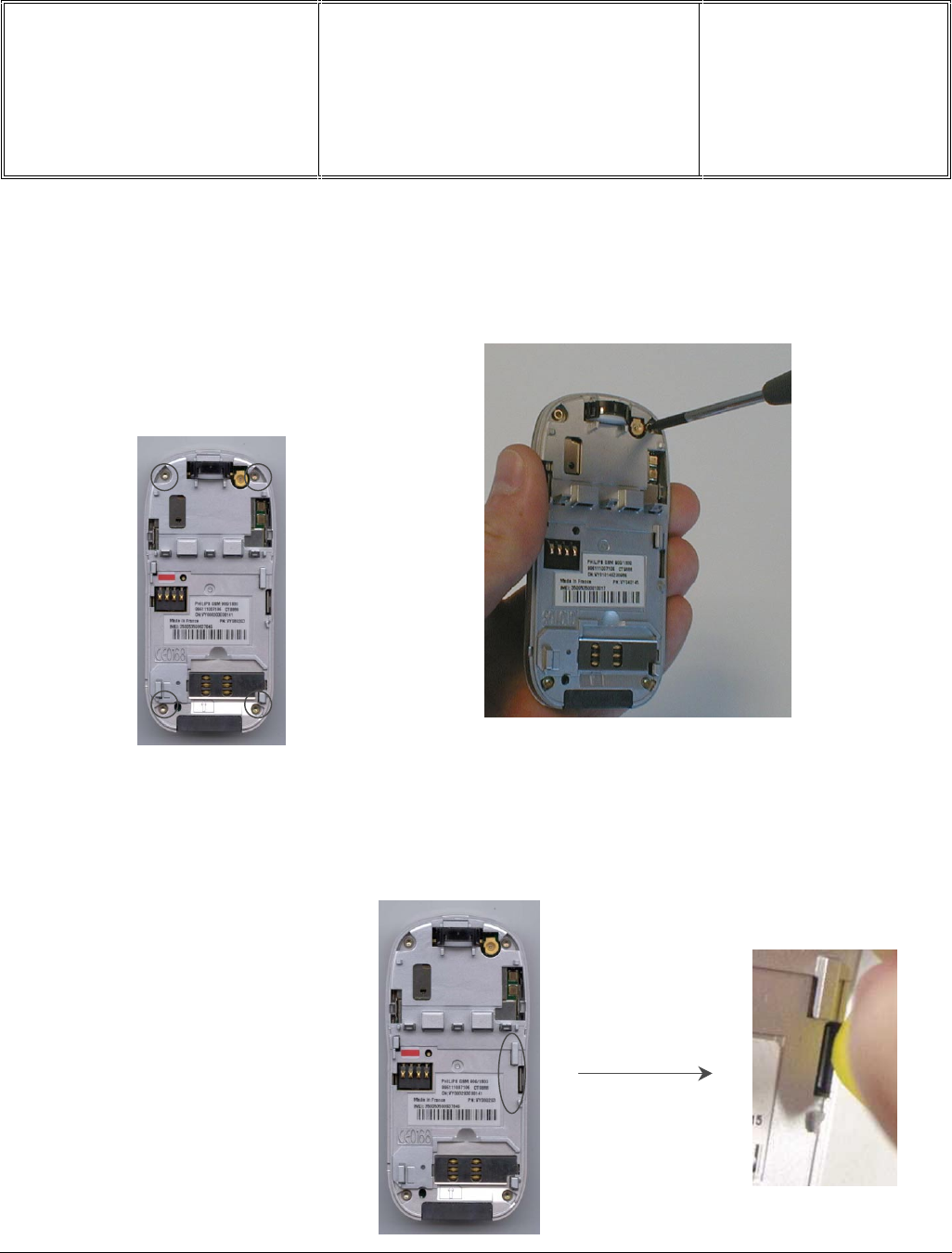
Départ. Technical support- CM640 PROCEDURE COMPANY RESTRICTED
PHILIPS Consumer
Communications
Centre du Mans
Service Repair Support VY-V-640-82x
Page : 55 of 71
Langue : EN
Date : 25/02/03
PHILIPS ELECTRONICS N.V. 1999 VY-V-640-82x
All rights reserved. Reproduction in whole
or in part is prohibited without the written
consent of the copyright owner.
9.1.3 Remove the 4 screws
9.1.4 Open the Front Cabinet
Remove the four screws on
the chassis assembly
Locate the slot at the middle,
right hand side of the rear
chassis. Insert the guitar pick
between the front cabinet snap
and the chassis, twist slightly to
unlatch this side of the interlock.
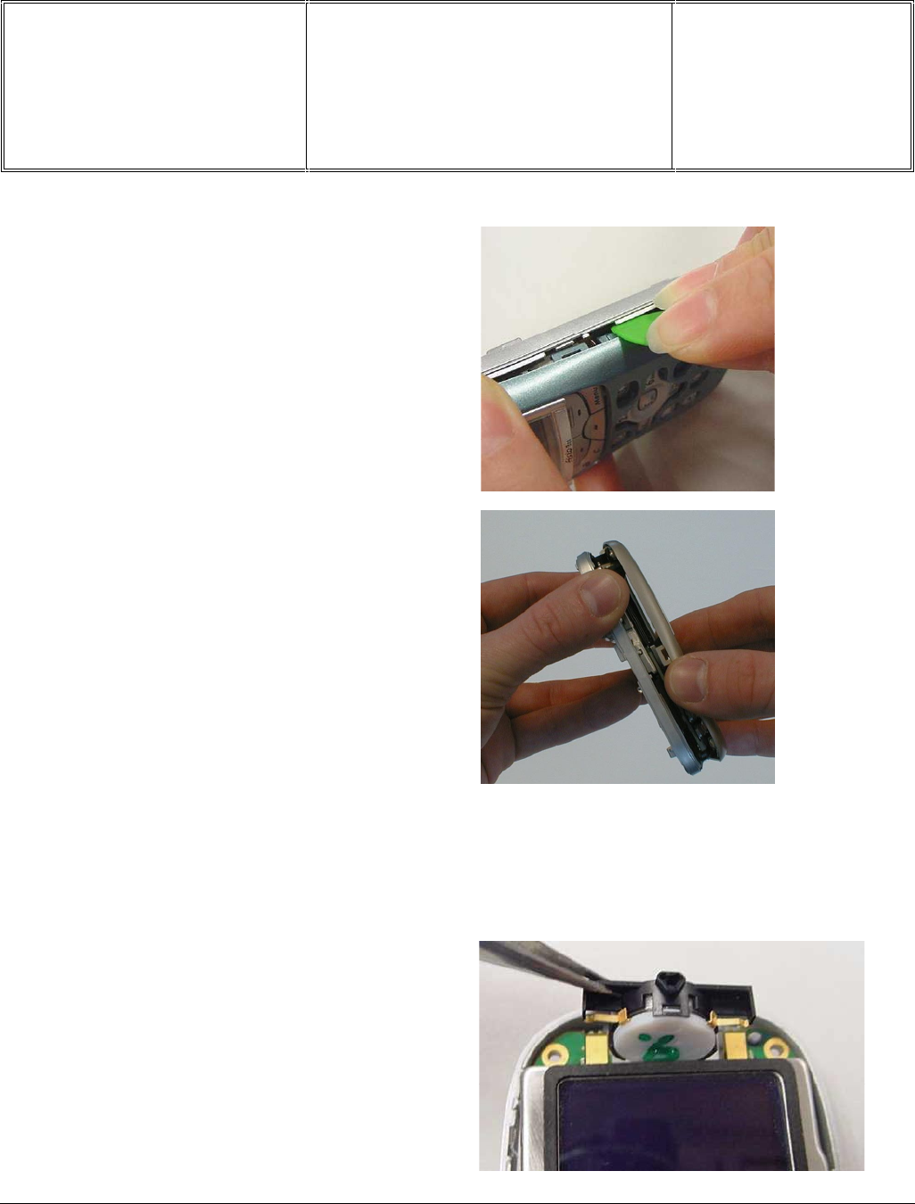
Départ. Technical support- CM640 PROCEDURE COMPANY RESTRICTED
PHILIPS Consumer
Communications
Centre du Mans
Service Repair Support VY-V-640-82x
Page : 56 of 71
Langue : EN
Date : 25/02/03
PHILIPS ELECTRONICS N.V. 1999 VY-V-640-82x
All rights reserved. Reproduction in whole
or in part is prohibited without the written
consent of the copyright owner.
Since the LCD is not protected by the Front Cabinet & Windows Ass’y take care to not apply your fingers on it and
keep it away form dust sources.
9.1.5 Remove the HP module (earpiece)
Remove the HP module from the Sub assembly.
Insert the guitar pick between the
Front Cabinet and the Chassis, twist
slightly to unlatch all the catches.
Then remove the Front Cabinet.
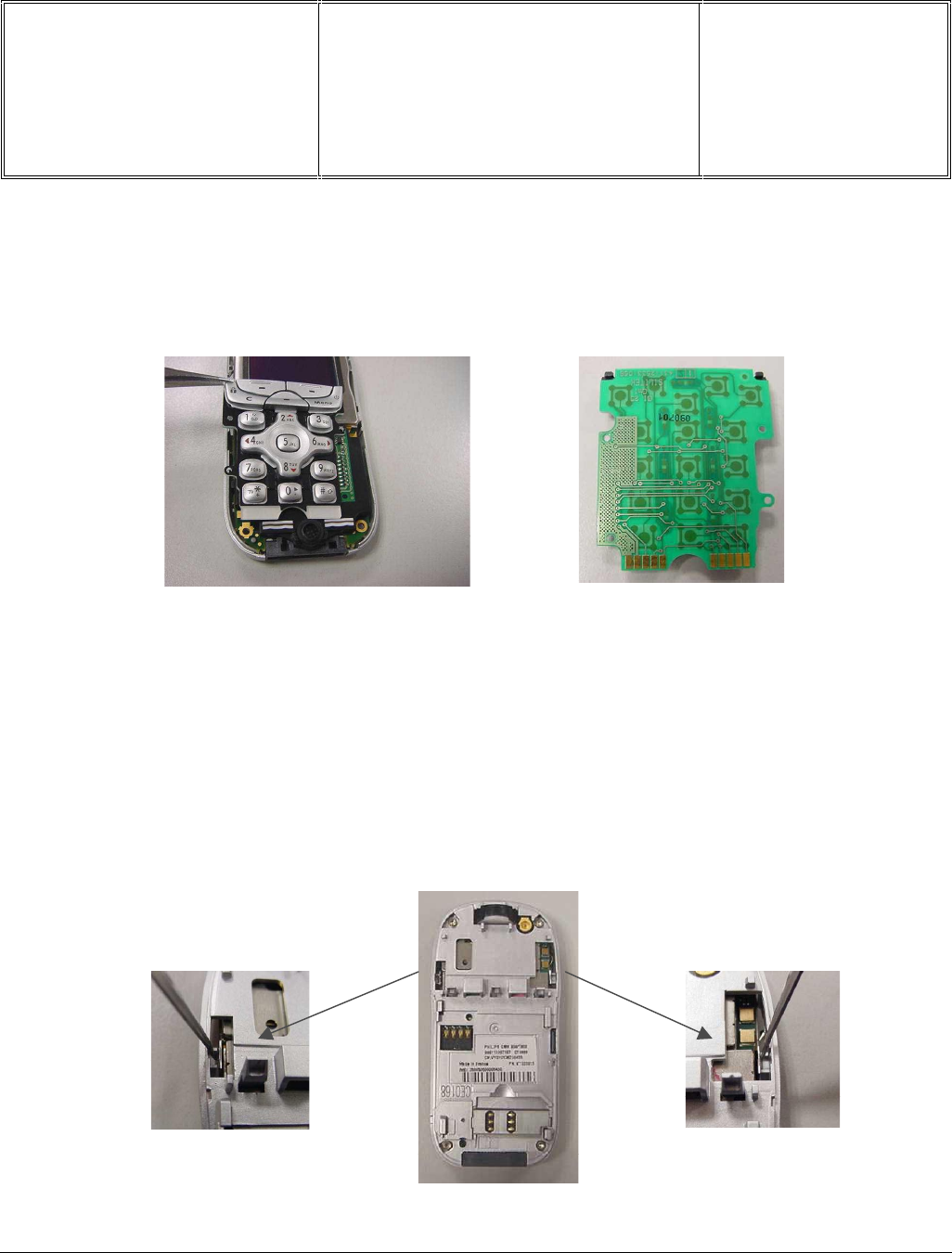
Départ. Technical support- CM640 PROCEDURE COMPANY RESTRICTED
PHILIPS Consumer
Communications
Centre du Mans
Service Repair Support VY-V-640-82x
Page : 57 of 71
Langue : EN
Date : 25/02/03
PHILIPS ELECTRONICS N.V. 1999 VY-V-640-82x
All rights reserved. Reproduction in whole
or in part is prohibited without the written
consent of the copyright owner.
9.1.6 Remove the keypad assembly
The keypad can be easily removed by lifting. Note that the keypad contact is via the zebra contact on the keypad
holder and the copper pads at the back of the keypad, there is no connection via connectors.
Take care to not apply your fingers on the copper areas and on the zebra contacts.
9.1.7 Separate the Sub Module form the Chassis Ass’y
The sub module is kept in place by the interlock on both sides of the LCD module.
From the rear of the chassis, insert the guitar pit between the LCD’s metal clip and the chassis, lightly push inwards
to unlatch the clip.
Repeat for the opposite side.
From the front, remove the sub module from the chassis.
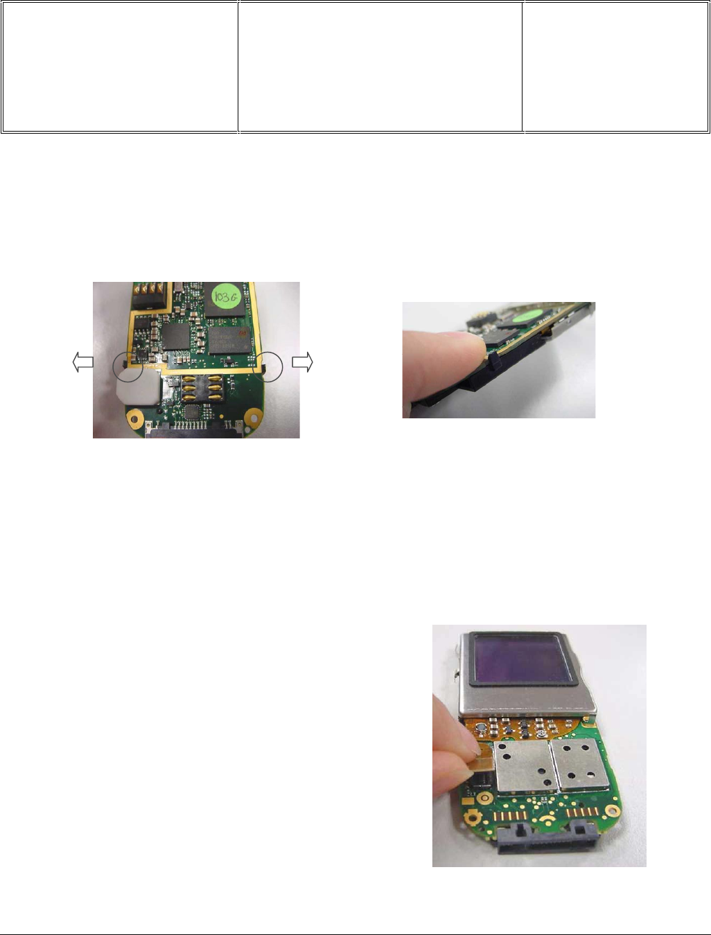
Départ. Technical support- CM640 PROCEDURE COMPANY RESTRICTED
PHILIPS Consumer
Communications
Centre du Mans
Service Repair Support VY-V-640-82x
Page : 58 of 71
Langue : EN
Date : 25/02/03
PHILIPS ELECTRONICS N.V. 1999 VY-V-640-82x
All rights reserved. Reproduction in whole
or in part is prohibited without the written
consent of the copyright owner.
9.1.8 Removing keypad holder from Main Board
To remove the keypad holder, simply pull outwards at both the clips at the side of the keypad holder so that it is
released from the PCBA main board.
Remove the microphone from the keypad holder
Using a tool or finger, push the microphone towards the back until it comes off the keypad holder
9.1.9 Removing the color LCD
Disconnect the LCD connector and the LCD
assembly can now be removed from the Main Board.
The LCD must be handle carefully. Handle it by the
edges. Do not put your fingers on the glass.
During repair operations , keep it in a dust free
location to prevent from dust contamination and
scratches.
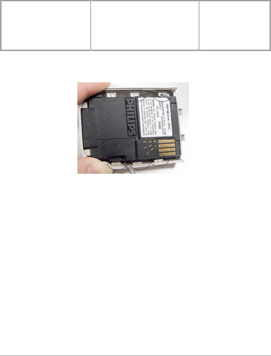
Départ. Technical support- CM640 PROCEDURE COMPANY RESTRICTED
PHILIPS Consumer
Communications
Centre du Mans
Service Repair Support VY-V-640-82x
Page : 59 of 71
Langue : EN
Date : 25/02/03
PHILIPS ELECTRONICS N.V. 1999 VY-V-640-82x
All rights reserved. Reproduction in whole
or in part is prohibited without the written
consent of the copyright owner.
9.1.10 Removing Battery Cover
Insert guitar pit/tip of a screwdriver, between the battery cover and the black battery cell assembly (near to the
catch location) to unlock the three side catches on both sides and also the top two catches (below the battery
catch).
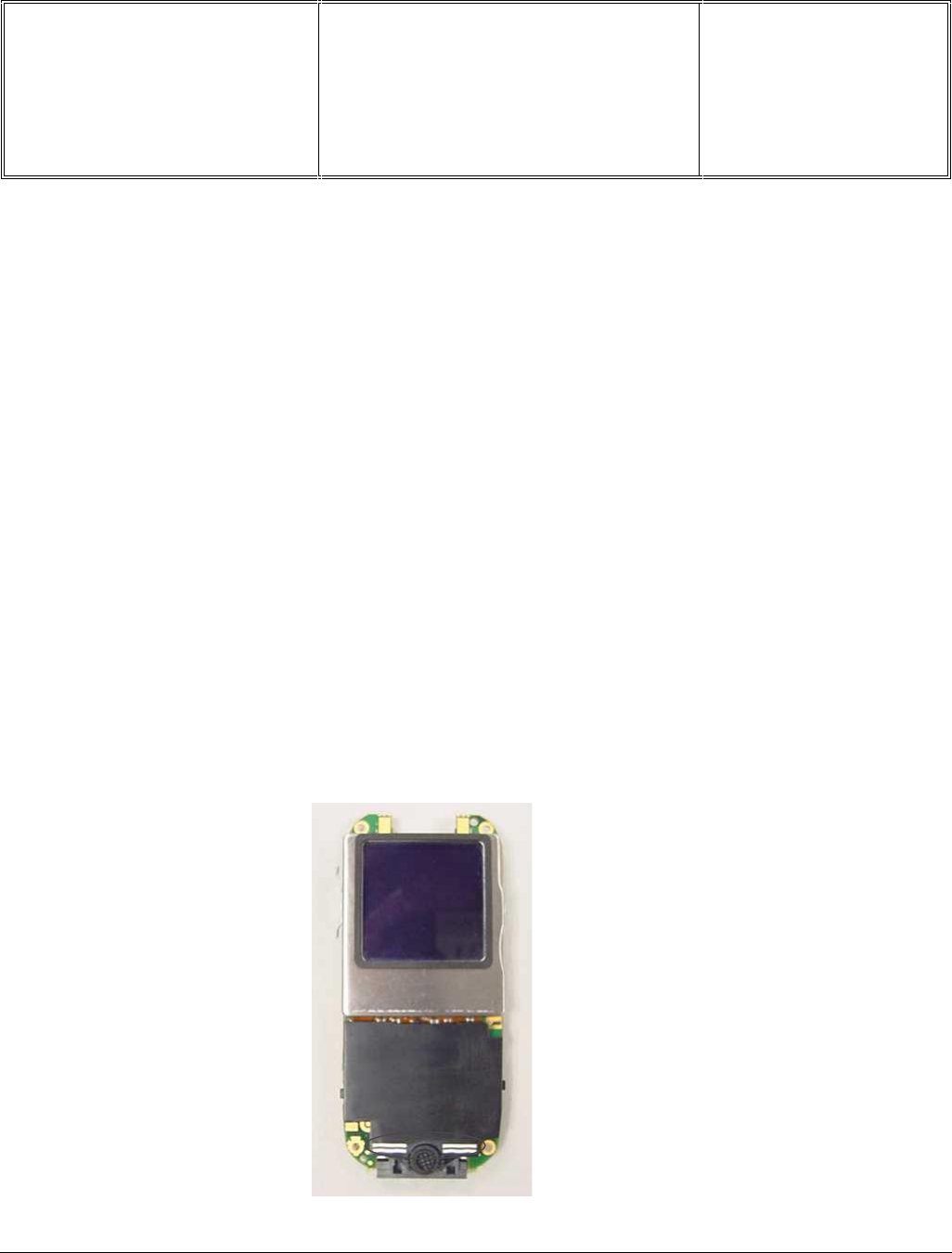
Départ. Technical support- CM640 PROCEDURE COMPANY RESTRICTED
PHILIPS Consumer
Communications
Centre du Mans
Service Repair Support VY-V-640-82x
Page : 60 of 71
Langue : EN
Date : 25/02/03
PHILIPS ELECTRONICS N.V. 1999 VY-V-640-82x
All rights reserved. Reproduction in whole
or in part is prohibited without the written
consent of the copyright owner.
9.2 Assembly
9.2.1 Attach the color LCD
Take a LCD Assembly and place it on the Main Board and fasten the connector to the LCD Connector which is
located on the Main Board.
In case of replacement by a new LCD do not forget to remove the Peel-off from the LCD.
9.2.2 Replace Keypad Holder
Align the keypad holder below the LCD metal frame. Press firmly at both sides to make sure that the two side clips
click on the Main Bord.
Note:
Ensure that zebra contacts sit nicely in place and that the microphone is attached to the keypad holder.
Also, make sure that zebra and microphone contacts are not corroded.
Check that zebra contacts and
microphone are in place

Départ. Technical support- CM640 PROCEDURE COMPANY RESTRICTED
PHILIPS Consumer
Communications
Centre du Mans
Service Repair Support VY-V-640-82x
Page : 61 of 71
Langue : EN
Date : 25/02/03
PHILIPS ELECTRONICS N.V. 1999 VY-V-640-82x
All rights reserved. Reproduction in whole
or in part is prohibited without the written
consent of the copyright owner.
9.2.3 Assembling rear chassis assembly
Align the Main Board on the Chassis assembly and press firmly on both sides of the LCD until it clicks onto the
Chassis assembly.
Main Board should
click from inside, onto
the sides of the
Chassis assembly.
Please check that the Buzzer Gasket
on the back of the Main Board is in
place.
Buzzer Gasket
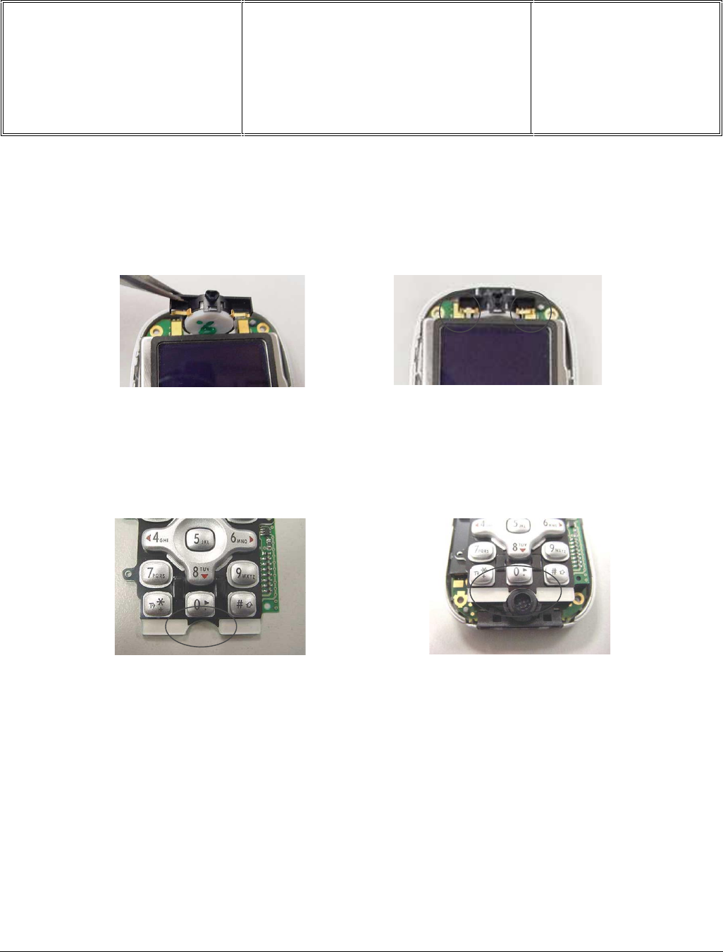
Départ. Technical support- CM640 PROCEDURE COMPANY RESTRICTED
PHILIPS Consumer
Communications
Centre du Mans
Service Repair Support VY-V-640-82x
Page : 62 of 71
Langue : EN
Date : 25/02/03
PHILIPS ELECTRONICS N.V. 1999 VY-V-640-82x
All rights reserved. Reproduction in whole
or in part is prohibited without the written
consent of the copyright owner.
9.2.4 Replacing the HP-module (earpiece)
Take an earpiece and insert it into the slot above the LCD module, making sure that the contact pins makes
contact with the copper pads of the PCBA.
9.2.5 Replacing the keypad
Take a keypad and place it on top of the keypad holder. The keypad has a curvature near the bottom that will sit
well above the microphone, this serves as a guide for the correct placement of the keypad.
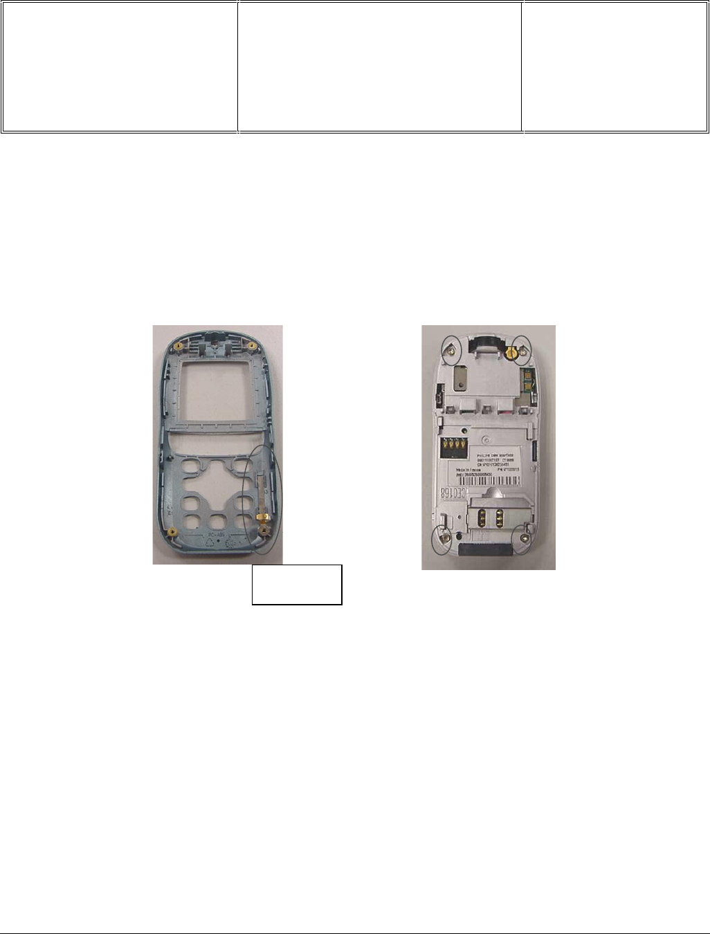
Départ. Technical support- CM640 PROCEDURE COMPANY RESTRICTED
PHILIPS Consumer
Communications
Centre du Mans
Service Repair Support VY-V-640-82x
Page : 63 of 71
Langue : EN
Date : 25/02/03
PHILIPS ELECTRONICS N.V. 1999 VY-V-640-82x
All rights reserved. Reproduction in whole
or in part is prohibited without the written
consent of the copyright owner.
9.2.6 Replacing the front cabinet
Check that the Bluetooth antenna is in place on the front cabinet (see diagram below). Reassemble the front
cabinet by placing it on top of the module and ensuring that it snaps onto the rear chassis assembly at the sides.
Secure the whole assembly by fastening the four screws on the rear.
Respect the Torque strength (0,18N/m +/-0.02)
Bluetooth
antenna
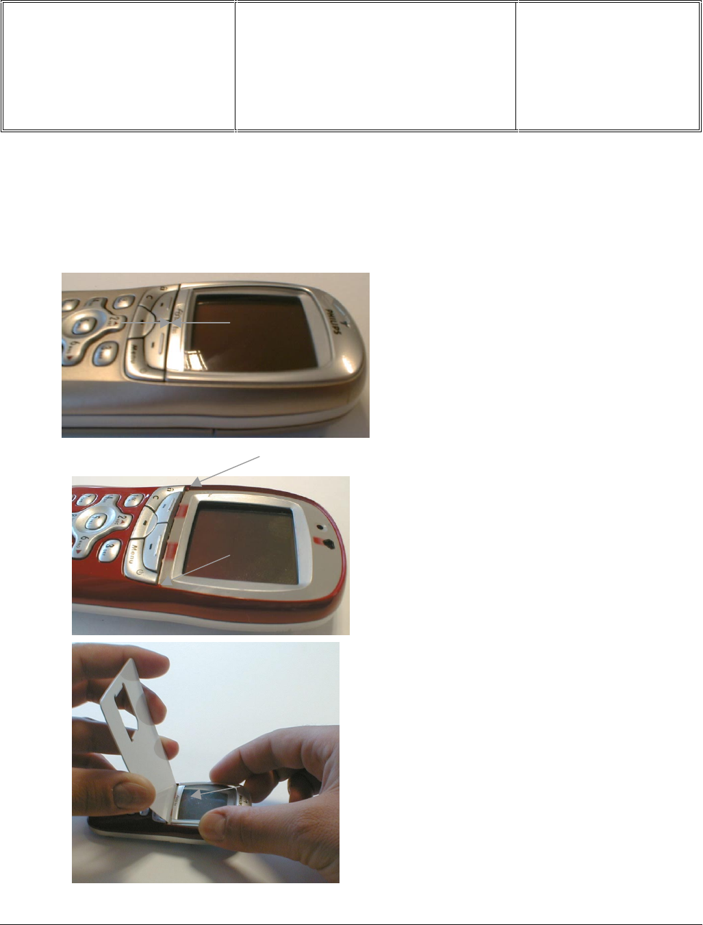
Départ. Technical support- CM640 PROCEDURE COMPANY RESTRICTED
PHILIPS Consumer
Communications
Centre du Mans
Service Repair Support VY-V-640-82x
Page : 64 of 71
Langue : EN
Date : 25/02/03
PHILIPS ELECTRONICS N.V. 1999 VY-V-640-82x
All rights reserved. Reproduction in whole
or in part is prohibited without the written
consent of the copyright owner.
9.2.7 Assembling the bezel
To prevent from key blocked a interspace of 1mm must be observed between the keypad and the window.
1mm
Two positioning tips are present on the
Front Cabinet.
The window have to lean against those two
tips.
Insert a Simcard holder as shown on the
picture, then apply the window. Press the
window against the
Simcard holder and set it
on the Front Cabinet. Then remove the
Simcard holder.
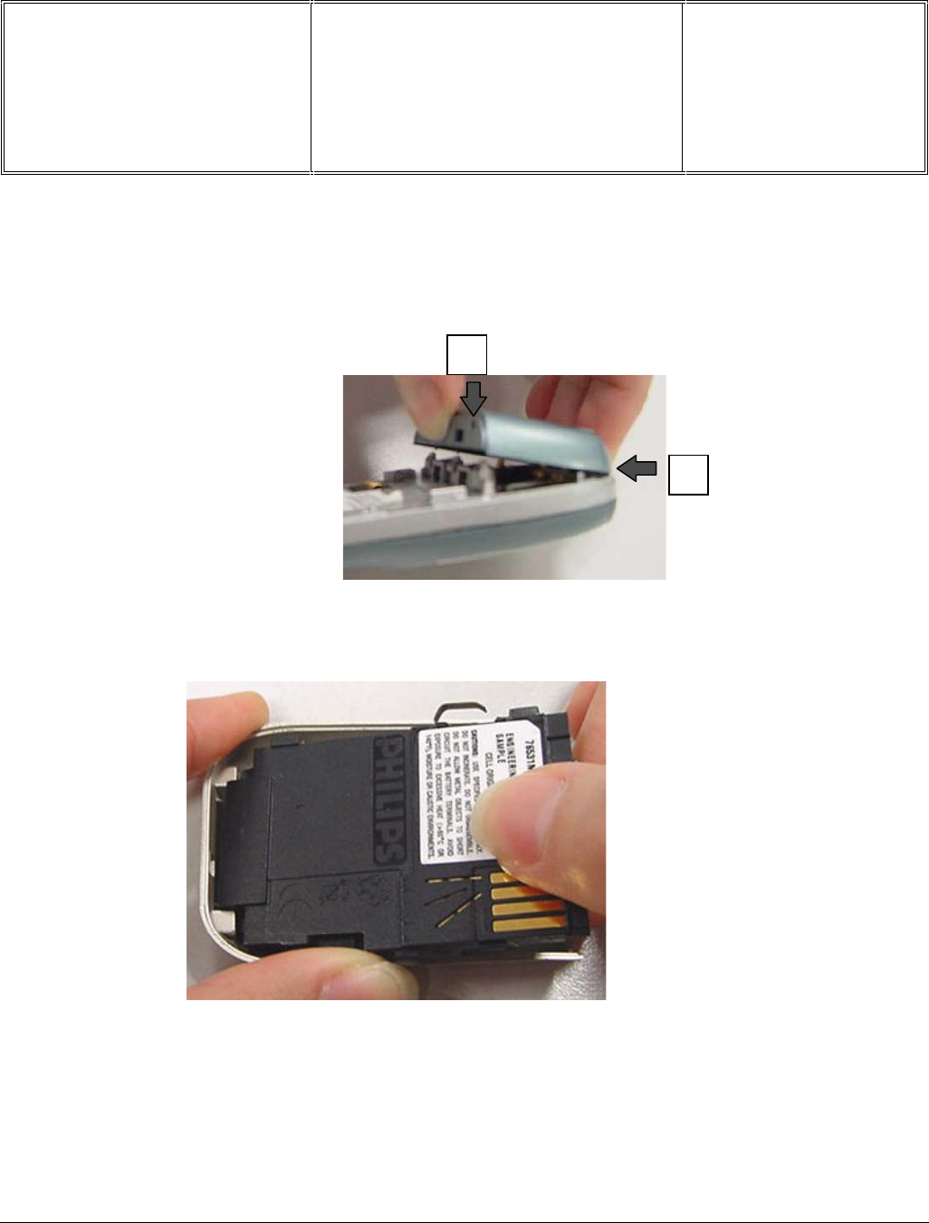
Départ. Technical support- CM640 PROCEDURE COMPANY RESTRICTED
PHILIPS Consumer
Communications
Centre du Mans
Service Repair Support VY-V-640-82x
Page : 65 of 71
Langue : EN
Date : 25/02/03
PHILIPS ELECTRONICS N.V. 1999 VY-V-640-82x
All rights reserved. Reproduction in whole
or in part is prohibited without the written
consent of the copyright owner.
9.2.7 Assembling the antenna cab
Fit the antenna cab from the top making sure that the top catch on the chassis catches onto the top of the antenna
cab, then press the antenna cab firmly until the three bottom catches snaps onto the rear chassis.
9.8 Replacing the Batter Cover
Insert the battery cell into the bottom of the battery cover. There are two tabs on the inside of the battery
cover, which should be concealed under the battery cell. Then, press the battery cell against the battery cover so
that all the top and side catches locks tightly.
If changing to a new battery cell, please ensure to paste on a new battery label or if replacing the battery cover,
please paste on a new rubber friction pad.
1
2
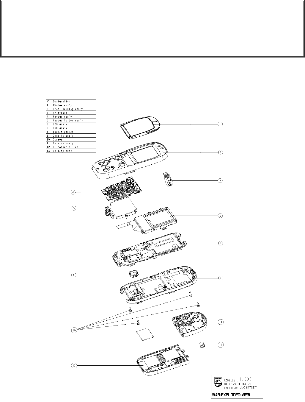
Départ. Technical support- CM640 PROCEDURE COMPANY RESTRICTED
PHILIPS Consumer
Communications
Centre du Mans
Service Repair Support VY-V-640-82x
Page : 66 of 71
Langue : EN
Date : 25/02/03
PHILIPS ELECTRONICS N.V. 1999 VY-V-640-82x
All rights reserved. Reproduction in whole
or in part is prohibited without the written
consent of the copyright owner.
9.3 Exploded view of the transceiver
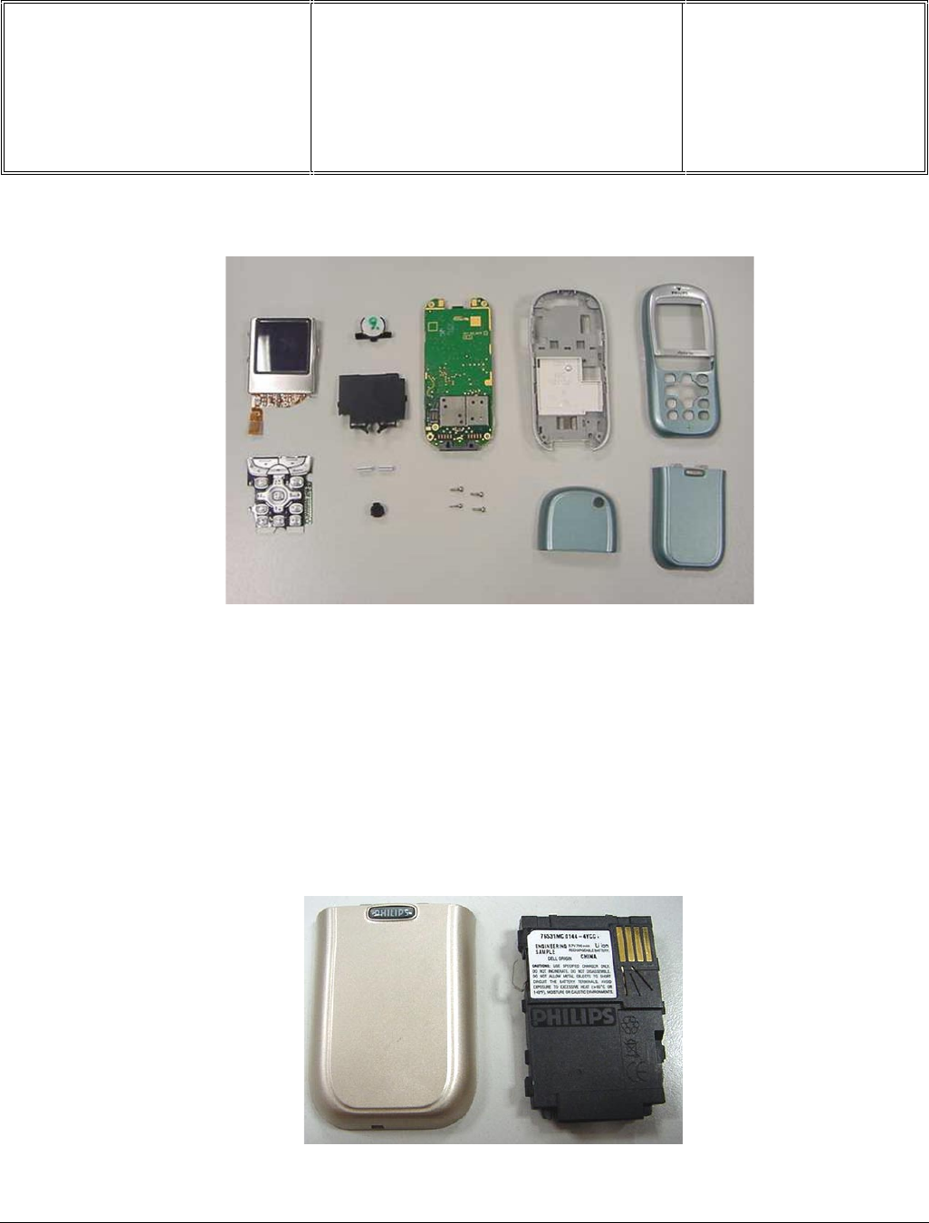
Départ. Technical support- CM640 PROCEDURE COMPANY RESTRICTED
PHILIPS Consumer
Communications
Centre du Mans
Service Repair Support VY-V-640-82x
Page : 67 of 71
Langue : EN
Date : 25/02/03
PHILIPS ELECTRONICS N.V. 1999 VY-V-640-82x
All rights reserved. Reproduction in whole
or in part is prohibited without the written
consent of the copyright owner.
1. Color LCD
2. Keypad
3. HP Module
4. Keypad Holder
5. Zebra contact
6. Microphone
7. PCBA main board
8. Screws
9. Chassis Assembly
10. Antenna Cab
11. Front Cabinet
12. Battery
2
1
3
4
5
6
7
8
9
10
11
12

Départ. Technical support- CM640 PROCEDURE COMPANY RESTRICTED
PHILIPS Consumer
Communications
Centre du Mans
Service Repair Support VY-V-640-82x
Page : 68 of 71
Langue : EN
Date : 25/02/03
PHILIPS ELECTRONICS N.V. 1999 VY-V-640-82x
All rights reserved. Reproduction in whole
or in part is prohibited without the written
consent of the copyright owner.
10.0 SOLUTIONS IN CASE OF PROBLEMS DURING THE TESTS
Under no circumstances the phone have to be disassembled to fix a defect detected during the test procedure on
level 1.
9.1 The phone does not switch on.
- Check the tactile feeling of the “ON/OFF” button.
- Remove the battery. Check that both the connectors of the phone and those of the battery are not damaged.
- Clean the connectors.
- Plug the battery again, making sure that it is securely fitted. Charge the mobile until the icon has stopped flashing.
Then unplug from the charger and attempt to switch the mobile on.
If it still does not switch on. If the failure can’t be found out then dismantle the product and swap the board.
9.2 Charge does not start or no detection of the charger. (refer to chapter 8.3)
- Check the charger contacts for dust or missing pins.
- Check the mobile connector.
- Remove the battery. Check that both the connectors of the phone and those of the battery are not damaged.
- Check the charger individually with a reference mobile. If the charger works properly try to charge the
customer mobile with a reference battery.
If neither of the battery and the charger can be incriminated, dismantle the mobile change the battery connector. If
the problem remains, swap the board.
9.3 The display shows “No SIM card. Please insert your SIM card.” or “SIM FAILURE”
- If the SIM card cannot be inserted, check for any foreign part and try to remove it.
- Check the SIM Card connector. All the contacts must be at the same level. Make sure that there is no dust on the
connector contacts and the SIM card contacts.
- If the test SIM card can be detected but the message “SIM Failure” remains on the customer’s card, his card must
be damaged. Ask him to contact his network operator.
Otherwise dismantle the product change the Simcard connector. If the problem remains, swap the board.
9.4 Display problems
Contrast, icons and matrix of the display can be checked with the test SIM card by pressing keys ”5”, “6” and “7” .
If everything works in test configuration that means that a phone setting is disabled or does not suit well. It can be
solved in the phone menu.
Otherwise dismantle the product change the LCD. If with a new LCD the problem remains, swap the board.

Départ. Technical support- CM640 PROCEDURE COMPANY RESTRICTED
PHILIPS Consumer
Communications
Centre du Mans
Service Repair Support VY-V-640-82x
Page : 69 of 71
Langue : EN
Date : 25/02/03
PHILIPS ELECTRONICS N.V. 1999 VY-V-640-82x
All rights reserved. Reproduction in whole
or in part is prohibited without the written
consent of the copyright owner.
9.5 Buzzer problems
Buzzer tone can be checked with the test SIM card by pressing key “1” and “Left arrowhead”.
- If it does not sound properly dismantle the mobile change the Buzzer. If the problem remains swap the board.
9.6 No sound in Loudspeaker
The sound from the loudspeaker can be checked with the test SIM card by pressing key “3”.
- Check the microphone and the earpiece, If needed dismantle the product change the loudspeaker then the
microphone. If the audio problem cannot be solved, swap the board.
9.7 Communication problems
- Sound quality can be checked in audio loop test (sound distortion, whistling, echo, …)
- If the mobile passes the radio tests successfully, we can assume that the phone works properly. The customer
must check the coverage area of his network operator or that he does not use the phone in a radio shadow
(outside the coverage area, in a tunnel or between tall buildings, …)
- If the mobile does not pass the radio tests, swap the board.
9.8 Keyboard problems
-The keyboard can be checked with the test SIM card.
- If a key or a row does not respond, check the keyboard. If needed dismantle the product change the keypad or
the keypad holder (including zebra connectors) . If the problem remains, swap the board.
9.9 Problems to send SMS messages
Check the Center number. It may be empty or wrong.

Départ. Technical support- CM640 PROCEDURE COMPANY RESTRICTED
PHILIPS Consumer
Communications
Centre du Mans
Service Repair Support VY-V-640-82x
Page : 70 of 71
Langue : EN
Date : 25/02/03
PHILIPS ELECTRONICS N.V. 1999 VY-V-640-82x
All rights reserved. Reproduction in whole
or in part is prohibited without the written
consent of the copyright owner.
11.0 RECOMENDED PART LIST CT9888 FISIO820
See File " FISIO 820 Lvl2 Components List.pdf " under the Internet Web Site
http://philipscscc.soft2you.net/ in " Technical Support \ Component List \ Wireless \ Fisio 820 " section
12.0 RECOMENDED PART LIST CT9889 FISIO825
See File " FISIO 825 Lvl2 Components List.pdf " under the Internet Web Site
http://philipscscc.soft2you.net/ in " Technical Support \ Component List \ Wireless \ Fisio 825 " section
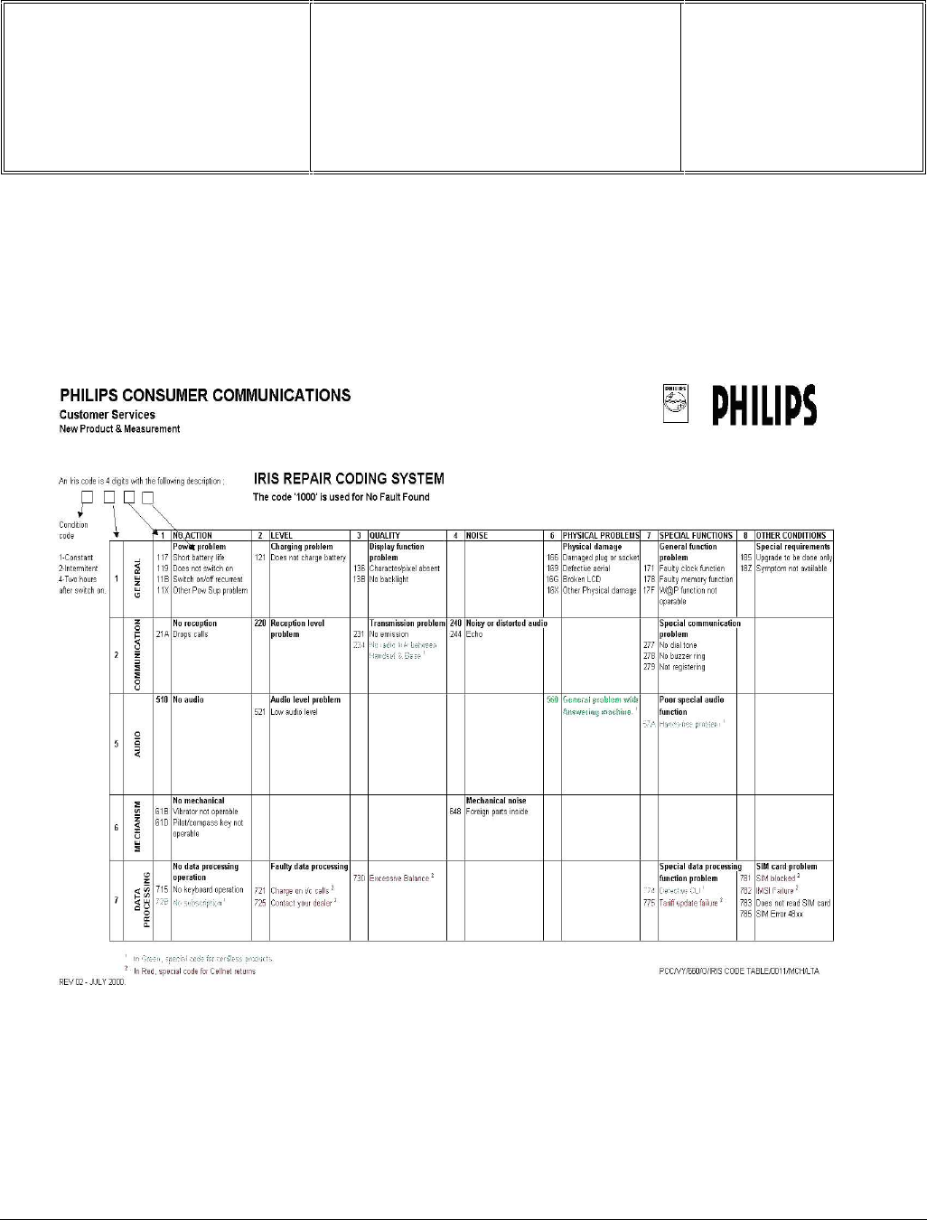
Départ. Technical support- CM640 PROCEDURE COMPANY RESTRICTED
PHILIPS Consumer
Communications
Centre du Mans
Service Repair Support VY-V-640-82x
Page : 71 of 71
Langue : EN
Date : 25/02/03
PHILIPS ELECTRONICS N.V. 1999 VY-V-640-82x
All rights reserved. Reproduction in whole
or in part is prohibited without the written
consent of the copyright owner.
ANNEX 1
