Record Usa A S8000InstallationSep11 8100 Series Swing Door Operator Installation Instructions 2523
User Manual: record-usa 8100 Series Swing Door Operator Installation Instructions Installation Instructions
Open the PDF directly: View PDF ![]() .
.
Page Count: 1
6
-USA
8000/8100 Series Swing Door Operator
Installation Instructions
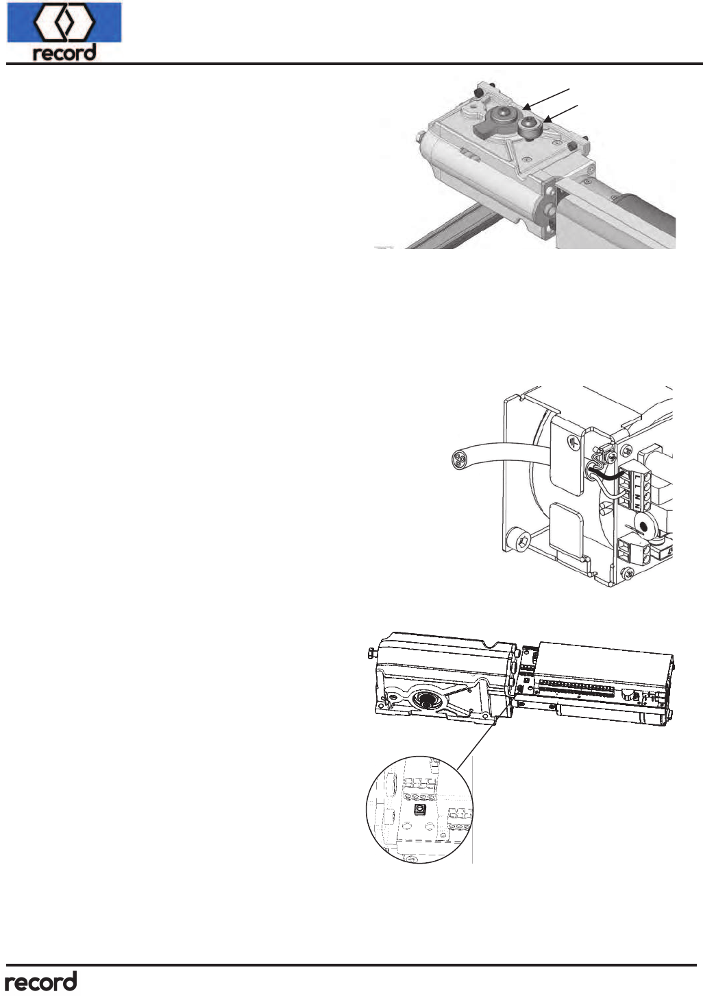
Open Stop
The unit is provided with an adjustable full open
stop. Rotate the door to the full open position;
mount the Shaft Stop onto the upper output shaft
and against the Fixed Stop. The spline of the out-
put shaft allows indexing in 6° increments.
For finer adjustment, the Fixed Stop is slightly ec-
centric; loosen and rotate until the desired stop
location is achieved and re-tighten.
For installations where severe physical abuse may occur (such as extreme wind conditions), it
is suggested a floor mounted stop be installed at full open. Additionally, the operator full open
stop can be set at 100 degrees or more of opening, and program the operator to electronically
stop at the 90 degree full open position. This can be accomplished by manually stopping the
door at 90 degrees during a calibration run, or by reducing the opening angle under the para-
meter “Drive / Opening angle” (using an FPC902 Hand Terminal or a Display Control Panel).
Power Supply Connection
Connect 115VAC, 60 Hz, 10A, to Power Supply terminal strip
115VAC "Hot" (Line) to "L" terminal;
115VAC "Neutral" to "N" terminal
The second "L" and "N" terminals provide a convenient
junction for dual operator systems.
Proper grounding must be provided for the unit. A grounding
tab and screw are located adjacent to the Power Supply ter-
minal strip.
The power supply cover must be installed after connecting
115VAC primary service.
The multifunction pushbutton can be used for
the following functions:
1 flash of the red LED will actuate a standard
open cycle (if the rocker switch is on).
3 flashes of the red LED will initiate a
calibration run.
4 flashes of the red LED will initiate the parame-
ter adjust mode of a Display Control Panel.
8 flashes of the red LED will reset the unit’s
parameters to factory defaults.
15-17 flashes will cause the unit to reset without
affecting any of the field set parameters.
After completion of the mechanical installation and prior to adjusting the parameters,
always initiate a calibration run by pressing and holding the pushbutton for 3 flashes of
the red LED. This will insure proper door operation by calibrating the unit to the instal-
lation conditions.
Shaft Stop
Fixed Stop
9/06
Updated
02/07
