scemtec Transponder Technology SIR-2720 Midrange Reader System User Manual
scemtec Transponder Technology GmbH Midrange Reader System
User Manual

State: 2010-03-01 Vers. no.: 1.10
m. dudde hochfrequenz-technik Rottland 5a D-51429 Bergisch Gladbach/ Germany Tel. +49 2207-96890 Fax +49 2207 968920
Annex no. 5
Functional Description /
User Manual

© scemtec transponder technology GmbH · Gewerbeparkstr. 20 · D-51580 Reichshof
Manual and Specification
SIR-
2720 (13.56 MHz Midrange Reader)
Project:
System version
Document version
SIR-2720
0.1.1 0.04
Creation date
Author
Revised
Author
24 Nov. 2010 M. Radermacher 31 Jan. 2011 M.Radermacher
Last date printed
Number of pages
31 Jan. 2011 14
Path:
p:\sir-2720\spezifikation (manual)\manual & specification\sir-2720_manual_engl._v.0.04.doc
Document number
0000.0000.2720
Project manager
Development manager
Managing director
M. Radermacher Jürgen Kalbitzer Rudolf Schmitz

Manual and Specification
SIR-2720 (13.56 MHz Midrange Reader)
Document No. SIR-2720 Version: 0.04 Page 2 of 14
Table of Contents
1 Introduction___________________________________________________________________ 3
2 System Description ____________________________________________________________ 4
3 Block Diagram_________________________________________________________________ 5
4 Operating Modes ______________________________________________________________ 5
4.1 Self-Test (Diagnosis) and STAND-BY Operation_____________________________________ 5
4.2 Reading / Writing Tags_________________________________________________________ 6
4.3 EAS Antitheft ________________________________________________________________ 6
5 Hardware _____________________________________________________________________ 6
5.1 Voltage Supply _______________________________________________________________ 6
5.2 Safeguarding, fuse-requirements_________________________________________________ 6
5.3 HF Unit _____________________________________________________________________ 6
5.4 External Antenna _____________________________________________________________ 7
5.5 Digital Signal Processing _______________________________________________________ 7
5.5.1
Processor _______________________________________________________ 7
5.5.2
Memory_________________________________________________________ 7
5.6 Interfaces ___________________________________________________________________ 7
5.6.1
RS232__________________________________________________________ 7
5.6.2
Ethernet ________________________________________________________ 8
5.6.3
USB ___________________________________________________________ 8
5.7 Inputs / Outputs ______________________________________________________________ 8
5.7.1
Binary Inputs_____________________________________________________ 8
5.7.2
Binary outputs____________________________________________________ 9
6 Software_____________________________________________________________________ 10
6.1 Firmware for the SIR-2720 13.56 MHz Midrange Reader _____________________________ 10
6.2 STX / ETX Interface Protocol ___________________________________________________ 10
7 Diagnosis____________________________________________________________________ 11
7.1 Self-Test (POST) ____________________________________________________________ 11
7.2 LEDs______________________________________________________________________ 11
7.2.1
External Diagnosis LEDs __________________________________________ 11
7.3 Label / Type Plate____________________________________________________________ 11
8 Mechanical Data / Housing _____________________________________________________ 11
9 Electrical Data ________________________________________________________________ 12
10 Conformity___________________________________________________________________ 13
10.1 CE Conformity ______________________________________________________________ 13
10.2 FCC Conformity: Information for USA____________________________________________ 13
11 Delivery Scope / Optional Equipment and Accessories ______________________________ 14
11.1 Manual, CD-ROM, Test Software, Protocol Description ______________________________ 14
11.2 Optional Accessories / External Antenna(s)________________________________________ 14
12 Datasheet____________________________________________________________________ 14
13 Related Documents / Document History __________________________________________ 14
13.1 Document History____________________________________________________________ 14

Manual and Specification
SIR-2720 (13.56 MHz Midrange Reader)
Document No. SIR-2720 Version: 0.04 Page 3 of 14
1 Introduction
As with all electronic systems, the system described hereafter may also not be used for any
applications critical for maintaining safety. This means, the products may not used in life
support applications or any other life critical applications that could involve potential risk of
death, personal injury or severe property or environmental damage.
The user/operator is solely responsible for any damages resulting from an improper or
unintended utilization of the system.
scemtec Transponder Technology GmbH (STT) reserves the right to make changes or to discontinue its
products or services at any time without notice.
STT takes no responsibility for customer applications, products, or performance relating to systems or
applications incorporating with STT products.
STT assumes no liability and is not responsible for infringement of patents and/or any other intellectual
or industrial property rights of third parties, which may result from assistance provided by STT.
The Windows
®
logo is a registered trademark of Microsoft Corp.
All other products mentioned in this document might be brands or brand names of the different
suppliers.
Copyright
©
2007 scemtec Transponder Technology GmbH (STT)
General:
As this technology is based on radio frequency, one must exercise the following operational and
mounting instructions to achieve best operation:
• Metal affects radio signals. Normally the antenna has to be as far away as possible from any
metal object and it’s damping influence on the magnetic field. Only this leads to the best
distribution of the magnetic field in the reading range. Very important as well is not to have “short
circuits”, in the vicinity of the antenna, damping the magnetic field. A “short circuit” is any metal
near the antenna, building a “metallic ring”, so that currents introduced by the RF-field can flow,
destroying the energy needed for the tag to operate.
• Care must be exercised to reduce or eliminate unwanted signals (so called interference or
noise) from external sources. The reading range may be reduced by following noise sources:
• portable two way radio
• cellular phones
• switching power supplies
• computer monitors
• frequency converters (e.g. motor control systems)
• The read range is depending upon
• performance of the reader
• size of the antenna
• size of the tag (the bigger the better)
• orientation of the tag antenna plane to the reader antenna plane
• quality of the tag
• matching of reader antenna size and tag (-antenna) size
• environmental, electrical noise
• If influence of metal can not be fully avoided a tuning of the antenna is required and will
improve reading range
Manual and Specification
SIR-2720 (13.56 MHz Midrange Reader)
Document No. SIR-2720 Version: 0.04 Page 4 of 14
2 System Description
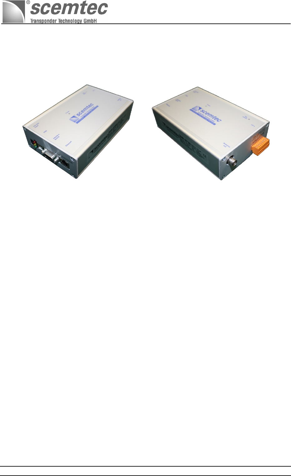
The "SIR-2720 13.56 MHz Midrange Reader System" is hereafter referred to as "Reader."
This manual describes the SIR-2720 13.56 MHz Midrange Reader System, Reader for short.
This SIR-2720 Midrange Reader System is designed as a multi-tag system to read and write information
stored on transponders (tags). The operating frequency of 13.56 MHz yields a relatively wide reading
range of up to 700 mm depending on antenna system (mainly with larger externally attached antennas)
and transponder -type and -size. This first generation of SIR-27xx Midrange Readers is based on the
hardware developed by scemtec Transponder Technology featuring an RF transmitting power of
max. 1.4W @ 50Ω-load. The SIR-2720 13.56 MHz Midrange Reader System is the second product in
the SIR-27xx product family. The transmission of data between the reader and a host computer via the
asynchronous RS232 interface can be up to 115200 baud. A USB 2.0 full speed compatible interface
and an Ethernet port is available as well.
The reader is compatible with standards ISO/IEC 15693- 2 and ISO18000-3 "A."
Manual and Specification
SIR-2720 (13.56 MHz Midrange Reader)
Document No. SIR-2720 Version: 0.04 Page 5 of 14
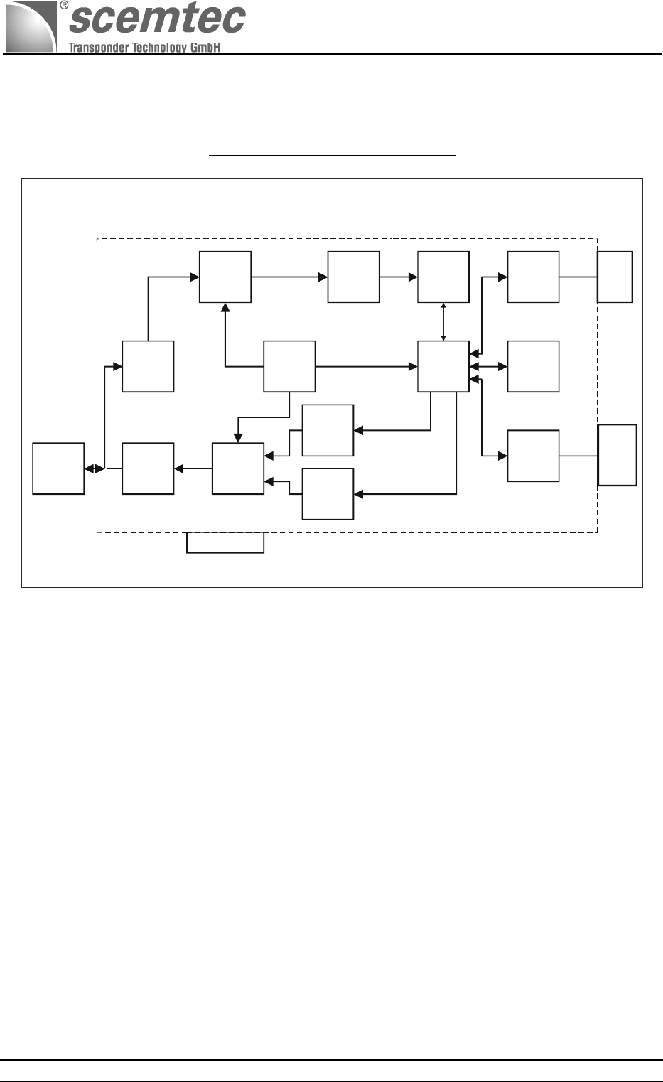
3 Block Diagram
13.56 MHz Midrange Reader System:
Power supply
12 V =/DC
external
antenna
(via BNC-
connector)
Mod- Unit
FILTER
Power
Switching
Unit
FILTER
MIXER
OSZ
13,56 MHz
Demod- Unit
A / D
Converter
Digital
Inputs
Outputs
USB
RS 232
Ethernet
25MHz
18,432MHz
DSP
EEProm
Interface
18,432MHz
Block - Diagramm SIR - 2720 13,56 MHz Midrange Reader System
PA
Analog
Digital
4 Operating Modes
4.1 Self-Test (Diagnosis) and STAND-BY Operation
After the main power supply has been switched on, a green LED labeled POWER lights up, which also
supplies power to the CPU unit. The reader is ready for operation after a short self-test. The reader
carries out a short self-test each time it is switched on. This tests all key components and functions of
the reader. Once the diagnosis routines have completed successfully, the software switches to IDLE
mode, i.e. the program waits for input via one of the three described ports of the interface to switch to a
different operating mode.
At this time, the antenna does not yet transmit since the carrier is still switched off. The hardware is in
STANDBY operating mode, the carrier is not active, and the energy consumption of the reader is
minimal. The carrier is automatically switched on once the reader receives a command from the host
sent across the interface, which the reader can only carry out with activated carrier. If there is no input
for a longer period of time after executing the command, the carrier is switched off again and the
hardware enters the STANDBY mode again as well. The time until the carrier is switched off can be set
with the software.
It is also possible to set the carrier to a stable on or off state using the software.
Manual and Specification
SIR-2720 (13.56 MHz Midrange Reader)
Document No. SIR-2720 Version: 0.04 Page 6 of 14
4.2 Reading / Writing Tags
Several tags in the field can be read or written simultaneously (anti-collision). The duration of the
reading/writing process depends on the number of tags in the field. Generally, there is no max. number
of tags that are permitted in the field at the same time.
4.3 EAS Antitheft
EAS is an abbreviation of Electronic Article Surveillance. This operating mode serves to monitor items or
articles electronically. The tags in the field are neither read nor written. The only thing determined is
whether a tag is in the field with a set EAS mode flag. This mode allows for greater ranges than the
read/write mode. When using an external antenna such as the scemtec SAT-A40-LR-O-13MHz with an
edge length of 400 mm (available as optional equipment), the detection range can be expanded up to
max. 700 mm.
Note: EAS mode is not supported by all silicon and transponder manufacturers.
5 Hardware
5.1 Voltage Supply
The standard version of the SIR-2720 reader in standard housing is designded for an input voltage
range of 12 Volt / =DC and a tolerance of +/_ 1Volt . The following input voltage ranges are thus
possible with the rated current consumptions in different operating modes:
Input voltage ranges:
= DC / direct current 12 volt
Input voltage - tolerance +/_ 1 volt
Current consumption of the different operating modes:
in STANDBY mode: @12 V / DC power supply ≤ 150 mA
while operating(carrier on):@12 V / DC power supply
≤ 800 mA
For the SIR-2720 reader system is a suitable wall plug 12 volt =DC / 1000mA power supply also as
optional accessory available and contactable to the SIR-2720 over a 2.1-mm standard barrel connector.
5.2 Safeguarding, fuse-requirements
Regarding the safety requirements for the SIR-2720 a standard TR5-fuse T1A / 250V (slow blow fuse) is
used to protect the complete electronics inside against short circuits or overcurrent .
It is required that this fuse should only be changed by trained technician or skilled personnel !
5.3 HF Unit
The carrier frequency of 13.56 MHz is generated in the HF unit. The final stage generates an output of
max. 1.4 watt on nominal Z
F
= 50 Ω.
Manual and Specification
SIR-2720 (13.56 MHz Midrange Reader)
Document No. SIR-2720 Version: 0.04 Page 7 of 14
5.4 External Antenna
The reader is only operational with an external antenna. The operating frequency f
0
amounts to
13.56MHz with a max. RF output of 1.4W on nominal Z
F
= 50 Ω. Some key parameters of the reader
such as range, for example, depend on the used antenna, the used transponder type and size and
quality, and the resulting magnetic coupling between the transponder resonant circuit and the
transmission/receiver antenna.
Normaly only one external antenna can be connected with a BNC plug connection located on the front of
the cable inlet side (see port labeled “Antenna out”). Optional the SIR-2720 reader system can be
delivered in the max. increment with two external antenna ports and cyclically multiplexed via software
(host-controlled or autarc in combi-mode). When operating with the external antenna, this antenna
should be configured for the optimal resonance frequency of 13.56MHz with ohmic adjustment (nominal
Z
F
= 50 Ω) to ensure the best possible adjustment to the SIR-2720 13.56MHz Midrange Reader System.
Recommended external antennas are scemtec antenna models:
SAT-A11-LR-O-13MHz 600 mm diameter Loop antenna
SAT-A40-LR-O-13MHz 400 mm * 400 mm Loop antenna
SAT-A4-LR-P-13MHz 200 mm * 200 mm Loop antenna
5.5 Digital Signal Processing
5.5.1 Processor
A Texas Instruments digital signal processor (DSP) is utilized.
5.5.2 Memory
The utilized memory consists of flash memory. The flash memory firmware can be updated at any time
using one of the three interfaces to be activated. A serial EEPROM to store the configuration data is
standard equipment.
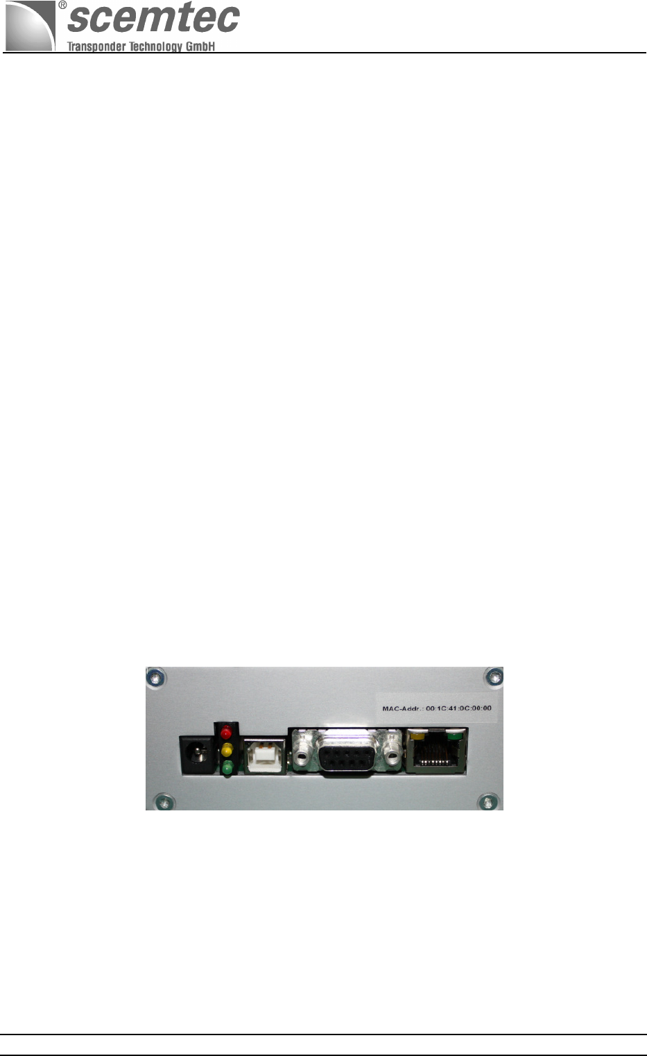
5.6 Interfaces
Interface-connectors of the SIR-2720 13.56 MHz Mid-Range Reader System
5.6.1 RS232
The RS232 interface serves to connect the SIR-2720 13.56MHz Midrange Reader System with a host
computer. The connection is made using the 9-terminal D-SUB plug labeled RS232. Each data transfer
starts with a start bit followed by eight data bits and one stop bit. Parity is configured as no parity. Please
consult the current scemtec STX/ETX protocol description and specification for additional information
about the interface protocol.
The speed at which the entire reader system and the host computer are working is significantly affected
by the data transfer between reader and host. This data transfer rate is adjustable using the software of
the SIR-2720 13.56MHz Midrange Reader System. This involves a standard RS232 interface cable.
Manual and Specification
SIR-2720 (13.56 MHz Midrange Reader)
Document No. SIR-2720 Version: 0.04 Page 8 of 14
Configurable Data Transfer Rates
1200 bits/sec
2400 bits/sec
4800 bits/sec
9600 bits/sec
19200 bits/sec
38400 bits/sec
57600 bits/sec
115200 bits/sec
5.6.2 Ethernet
The 13.56MHz Midrange Reader System SIR-2720 is equipped with a 10/100 T-Ethernet interface.
5.6.3 USB
The SIR-2720 13.56MHz Midrange Reader System is equipped with a USB 2.0 full speed (12 Mbits/sec)
port.
Please consult the separate SEC-1500 interface-specification for additional details!
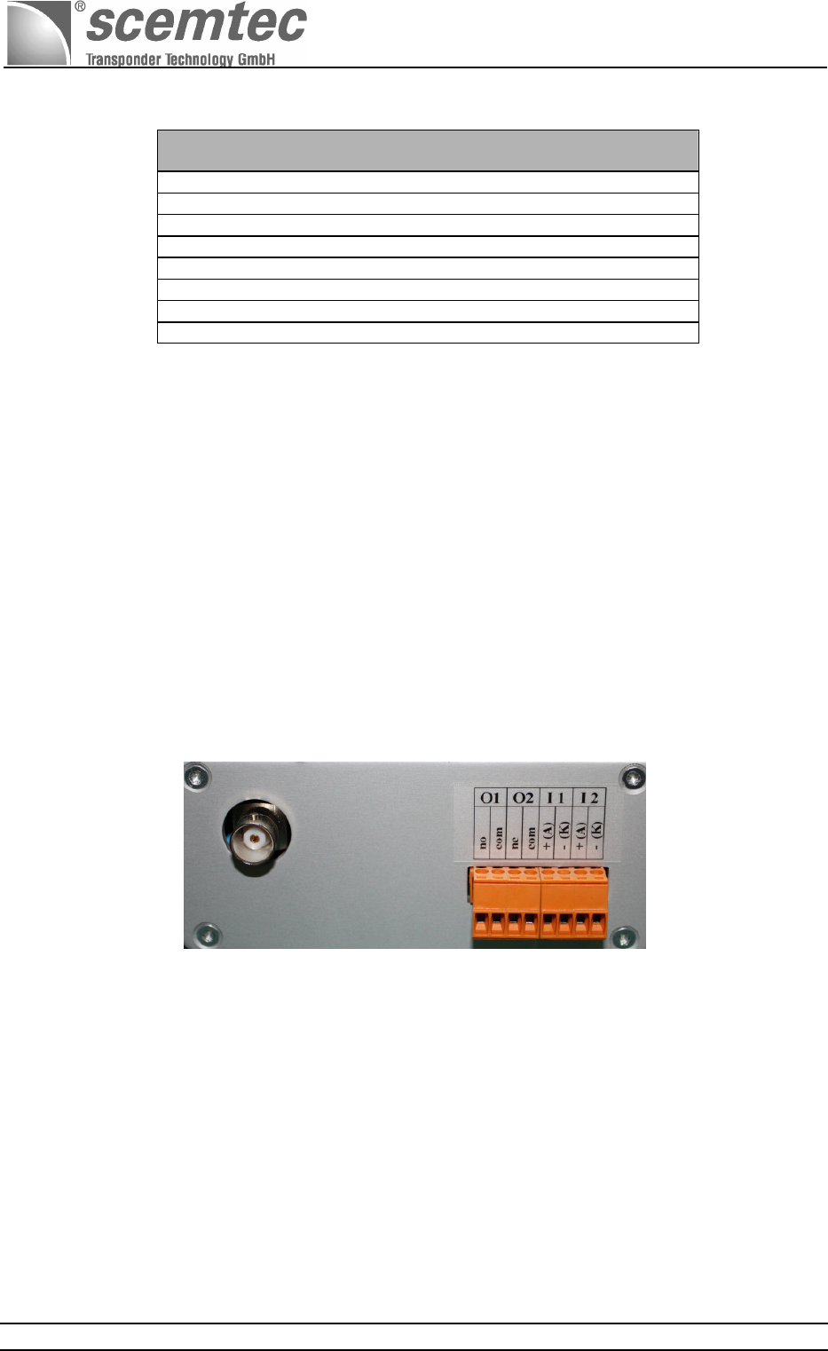
5.7 Inputs / Outputs
Inputs/outputs of the SIR-2720 13.56 MHz Mid-Range Reader System
5.7.1 Binary Inputs
Two binary inputs are available for customer-specific tasks. Both inputs are accessible with indirect-
connected optoisolators and screw terminals (see terminal description below). Both inputs pins
(photodiode) of the optoisolator are direct routed to the screw terminals. This means the input current
should amount to at least 5 mA and max. 10 mA with a defined input voltage of up to max. 24 VDC using
a suitable dropping resistor. For example, this results in a dropping resistor value of approx. 4.7 kOhm,
which must be still terminated externally, for an input voltage of 24 VDC and a required input current of
the photodiode of 5 mA.
The state of both binary inputs must be imported unambiguously using the software; see software
description STX/ETX protocol.
Manual and Specification
SIR-2720 (13.56 MHz Midrange Reader)
Document No. SIR-2720 Version: 0.04 Page 9 of 14
Terminal assignment:
Input designation: Terminal designation: Internal photodiode assignment:
I 1 + (A) Anode of the optoisolator input 1 Input 1
I 1 – (K) Cathode of the optoisolator input 1
I 2 + (A) Anode of the optoisolator input 2 Input 2
I 2 – (K) Cathode of the optoisolator input 2
All screw terminals are clearly marked with their specific terminal designation using a suitable label at
the terminal. The screw terminals make possible contact via a wire cross section of max. 2.5mm².
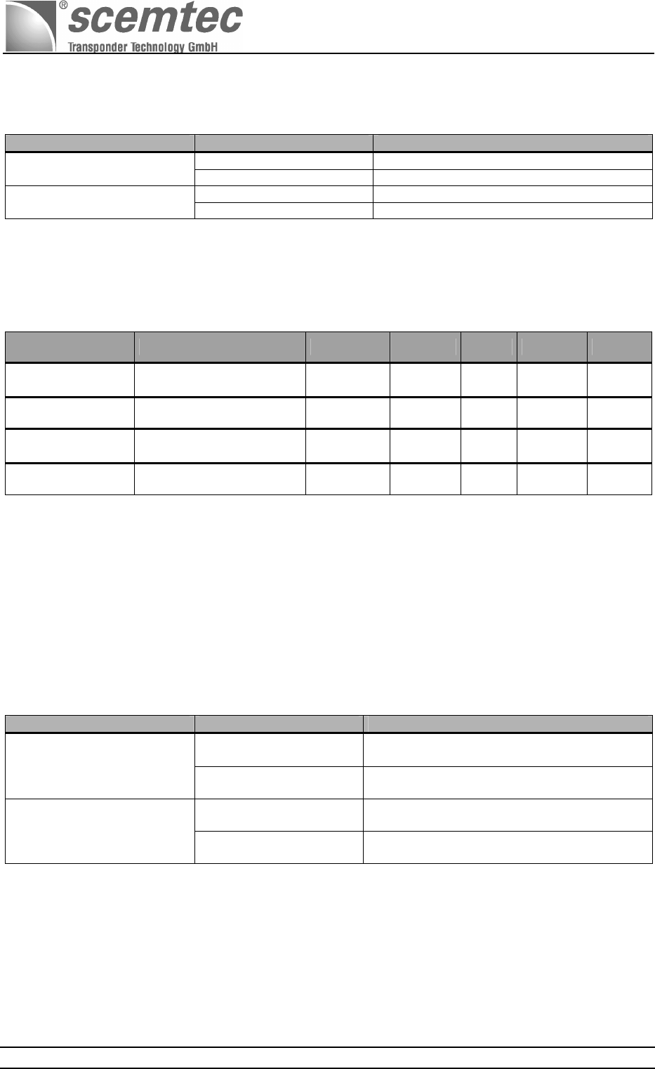
Electrical data:
Parameter: Input: Symbol: Min. Typ. Max. Unit
Input voltage Input 1 I1 5 - 24 Volt /
DC
Input current Input 1 I1 5 7,5 10 mA
Input voltage Input 2 I2 5 - 24 Volt /
DC
Input current Input 2 I2 5 7,5 10 mA
5.7.2 Binary outputs
Two binary outputs in the form of potential-free contacts are available for customer-specific tasks. Both
outputs are accessible with indirect-connected relays and screw terminals (see terminal description
below). They are freely configurable with the software; see software description STX/ETX protocol.
The following tables describes the terminal assignments and the electrical data (e.g. contact rating) of
the individual contacts.
Terminal assignment:
Input designation: Terminal designation: Internal photodiode assignment:
O 1 (no) Make contact output of the potential-free
contact of output 1
Output 1
O 1(com) Ref. point for make contact output of the
potential-free contact output 1
O 2 (nc) Break contact output of the potential-free
contact of output 2
Output 2
O 2(com) Ref. point for break contact output of the
potential-free contact output 2
All screw terminals are clearly marked with their specific terminal designation using a suitable label at
the terminal. The screw terminals make possible contact via a wire cross section of max. 2.5mm².
Manual and Specification
SIR-2720 (13.56 MHz Midrange Reader)
Document No. SIR-2720 Version: 0.04 Page 10 of 14
Electrical data:
Parameter: Output: Symbol: Min. Typ. Max. Unit
Output
switching voltage Output 1 O 1 - 24 40 Volt
AC / DC
Output
switching current Output 1 O 1 - 50 100 mA
Output
switching voltage Output 2 O 2 - 24 40 Volt
AC / DC
Output
switching current Output 2 O 2 - 50 100 mA
Contact ratings of
the output contacts Output 1 / 2 O 1 / O 2 - 500 800 mWatt
Internal resistance
of the output
contacts
Output 1 / 2 O 1 / O 2 - 25 35 Ω/Ohm
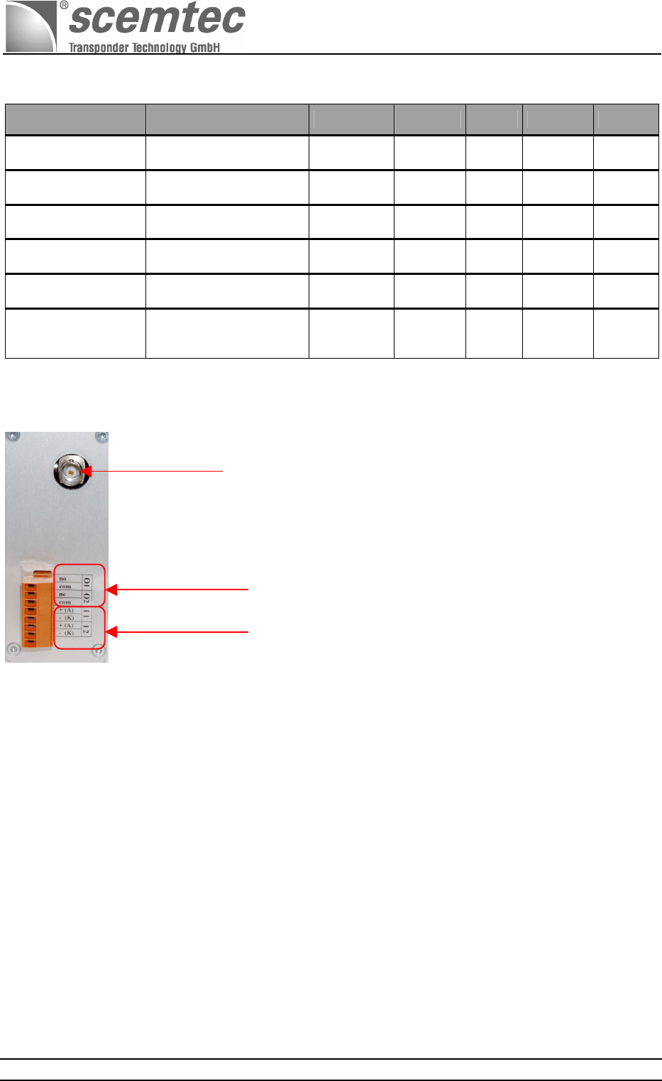
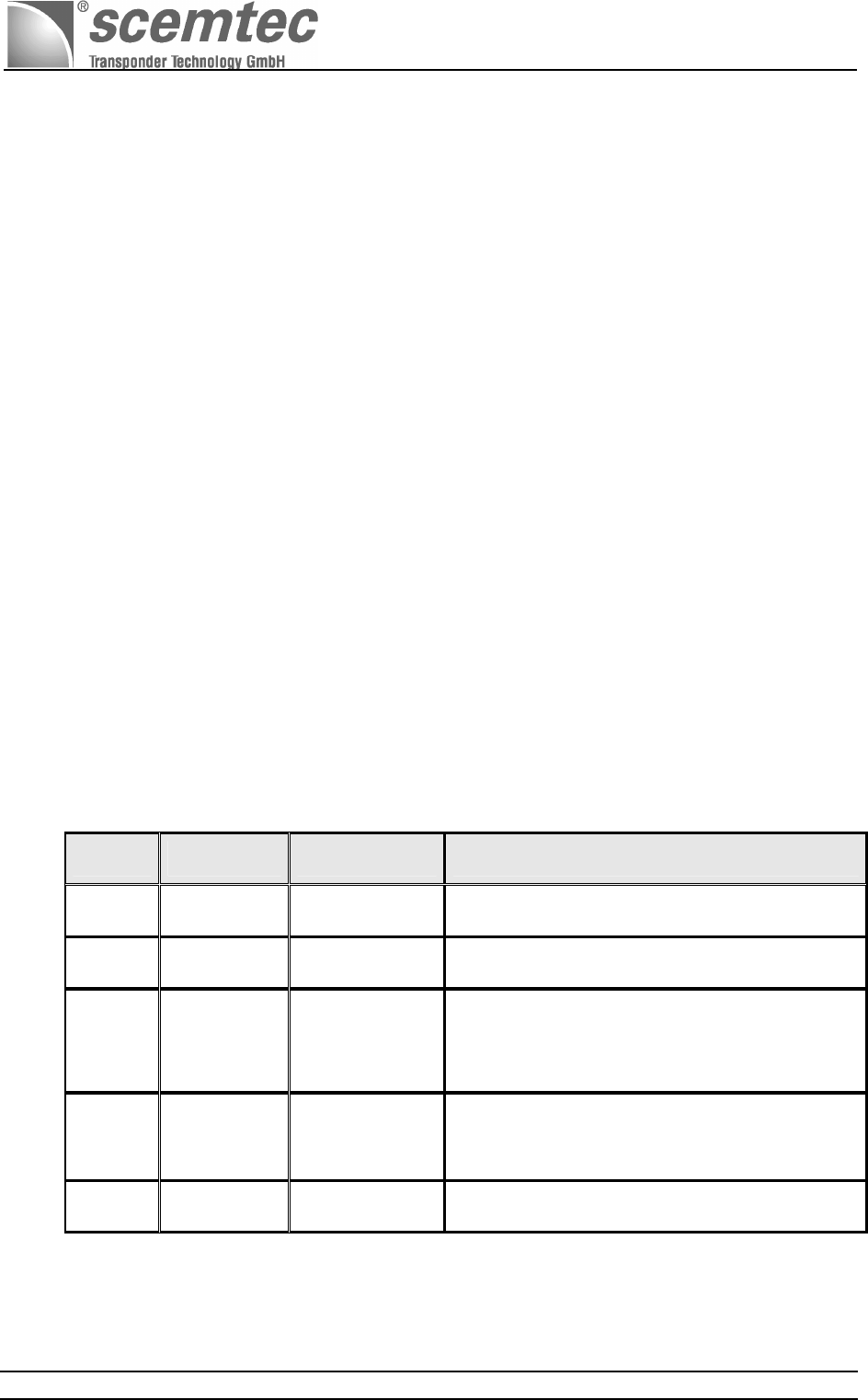
Connection options for binary inputs/outputs and HF antenna:
6 Software
6.1 Firmware for the SIR-2720 13.56 MHz Midrange Reader
The firmware for the SIR-2720 13.56 MHz Midrange Reader contains all basic functions for reading and
writing of tags of different manufacturers (air protocol), numerous control functions, as well as different
diagnosis routines. These routines are used to test the key components and functions of the reader.
A demo software for Windows is included on the CD-ROM delivered together with the device.
6.2 STX / ETX Interface Protocol
A special transfer protocol is available for the SIR-2720 13.56 MHz Midrange Reader System
documented in the scemtec STX / ETX protocol. The required STX/ETX protocol description is included
on the CD-ROM delivered together with the device.
BNC connector for
external antenna
Binary outputs
Binary inputs
Manual and Specification
SIR-2720 (13.56 MHz Midrange Reader)
Document No. SIR-2720 Version: 0.04 Page 11 of 14
7 Diagnosis
7.1 Self-Test (POST)
A selftest POST (Power On Self Test) is carried out automatically after turning on or connecting to the
mains power supply. This also includes testing the key components and functions of the reader. Should
a malfunction occur while using the SIR-2720 13.56 MHz Midrange Reader System, simply load the
POST diagnosis by turning the unit (or the mains power supply) off and then on again. The displayed
error message then helps in solving the problem quickly and reliably. Numerous software commands for
a targeted diagnosis are available as well.
7.2 LEDs
7.2.1 External Diagnosis LEDs
Three external LEDs provide users with a diagnosis of the most important monitoring functions "Power" ,
"Tag Detect" and “EAS”
Three external LEDs to indicate important operating states
LED Color Designation Description
1 GREEN Power The voltage supply for the CPU is ensured
2 YELLOW Tag Detect A read or write process for the transponders in the magn.
field has concluded successfully
3 RED EAS EAS is an abbreviation of Electronic Article Surveillance
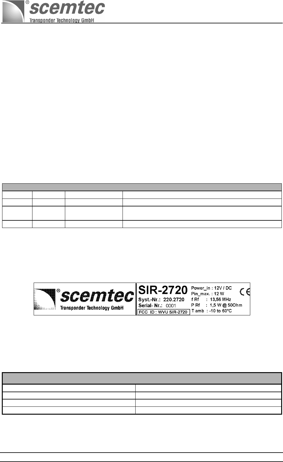
7.3 Label / Type Plate
The SIR-2720 13.56 MHz Midrange Reader System features a system label that provides information
about the specific scemtec system number "220.2720" and the consecutive serial number (four digits),
e.g. "0001" of the production lot.
8 Mechanical Data / Housing
An aluminum housing protection type IP 20 (in acc. with DIN EN 60529) is used. This housing is
equipped with two lateral covers attached with screws. Four screw channels and two installed fastening
rails (lugs) are used to mount the housing to the wall.
Case dimensions (exterior)
Length 185 mm
Width 130 mm
Height 44 mm
Color Natural matte aluminum
The following chapter lists the exact housing dimensions and detailed installation information.
Manual and Specification
SIR-2720 (13.56 MHz Midrange Reader)
Document No. SIR-2720 Version: 0.04 Page 12 of 14
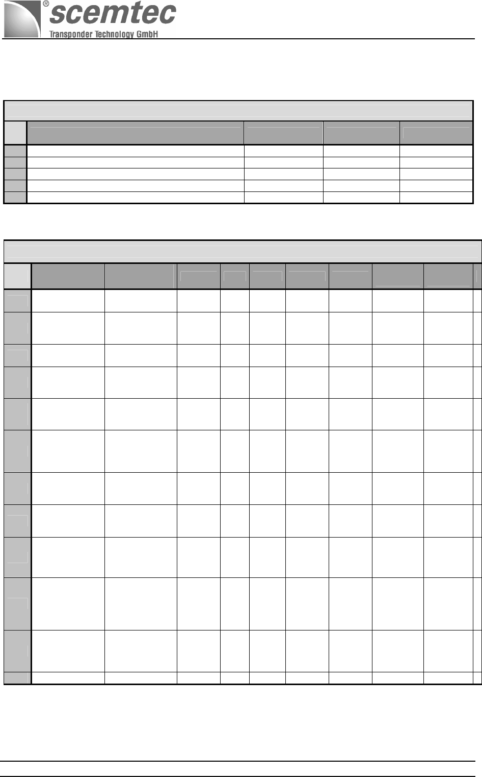
9 Electrical Data
Absolute Max. Parameters
No.
:
Parameter
Symbol
Value
Unit
1 Min. DC input voltage
V min
11 Volt
2 Max. DC input voltage
V max
13 Volt
3 Max. current consumption / @12Volt DCin
I max
850 mA
4 Operating (ambient) temperature range
T amb
- 10 to 60
°C
5 Storage temperature range
T stg
- 20 to 70
°C
General Parameters
No.
Parameter Test
condition
Symbol
Min.
Typ.
Max.
Unit
Min / Max
values
Typ.
values
6 Operating
frequency
Defined in
ISO document
F RF
- 13.56 - MHz
X
7 RF output-
power 50Ω
Terminal
resistance 50Ω
/25°C
P out
- 1db
1400 + 1db
mW
X
8 RF input
sensitivity
Pout = 1.4W
T amb = 25°C
- tbd
- dBm
X
9
Current
consumption at
U in = 12 Volt
RF out =1.4W
T amb = 25°C
I in
- 700 850 mA
(X)
X
11
Current
consumption at
U in = 12 Volt
STANDBY mode
T amb = 25°C
I in
- 120 150 mA
(X)
X
12
Transmission
rate
RS232 interface
Defined in DIN
66020
U in =12 V/DC
T amb = -10°C - 60°C
1200
- 115200 bits/sec
X
13
Input current
binary inputs
I1/ I2
U in =24 V/DC
R ext. = 4.7kΩ
T amb = -10°C - 60°C
I in-High
5 7.5 10 mA
X
see
5.7.1
14
Input current
binary inputs
I1/ I2
U in =24 V/DC
R ext. = 4.7kΩ
T amb = -10°C - 60°C
I in-Low
- - 0,5 mA
X
see
5.7.1
15
Output
switching voltage
binary outputs
O 1 / O 2
U out =24 V/DC
T amb = -10°C - 60°C
U out
(AC/DC)
- 24 40 V
X
see
5.7.2
16
Output
switching
current
binary outputs
O 1 / O 2
U out =24 V/DC
T amb = -10°C - 60°C
I out
- 50 100 mA
X
see
5.7.2
17
Output
switching output
binary outputs
O 1 / O 2
U out =24 V/DC
T amb = -10°C - 60°C
P out
- 500 800 mW
X
see
5.7.2

Manual and Specification
SIR-2720 (13.56 MHz Midrange Reader)
Document No. SIR-2720 Version: 0.04 Page 13 of 14
10 Conformity
10.1 CE Conformity
The company scemtec Transponder Technology GmbH declares that the product device type
13.56 MHz Mid Range Reader with the type designation
SIR-2720
complies with the basic requirements of Directive
1999/5/EC
of the European Council.
The following standards were used as the basis for this evaluation:
EN 300 330 (Part Radiated Spurious Emission)
Available soon: EN 301 489-1, -3
EN 60950
EN 50364
10.2 FCC Conformity: Information for USA
This device complies with Part 15 of the FCC Rules. Operation is subject to the
following two conditions:
(1) This device may not cause harmful interference, and
(2) this device must accept any interference received, including
Interference that may cause undesired operation.
Usually this is followed by the following FCC caution:
Any changes or modifications not expressly approved by the party
responsible for compliance could void the user's authority to operate this
equipment.
Note: This equipment has been tested and found to comply with the
limits for a Class A digital device, pursuant to part 15 of the FCC
Rules. These limits are designed to provide reasonable protection
against harmful interference when the equipment is operated in a
commercial environment. This equipment generates, uses, and can radiate
radio frequency energy and, if not installed and used in accordance with
the instruction manual, may cause harmful interference to radio
communications. Operation of this equipment in a residential area is
likely to cause harmful interference in which case the user will be
required to correct the interference at his own expense.
Professional Installation: To comply with FCC part 15 rules in the United States, the system must be
professionally installed to ensure compliance with the Part 15 certification.
It is the responsibility of the operator and professional installer to ensure that only certified systems are
deployed in the United States. The use of the system in any other combination (such as co-located
antennas transmitting the same information) is expressly forbidden.
Manual and Specification
SIR-2720 (13.56 MHz Midrange Reader)
Document No. SIR-2720 Version: 0.04 Page 14 of 14
11 Delivery Scope / Optional Equipment and Accessories
11.1 Manual, CD-ROM, Test Software, Protocol Description
11.2 Optional Accessories / External Antenna(s)
For the SIR-2720 reader system is a suitable wall plug 12 volt =DC / max.1000mA power supply as
optional accessory available and contactable to the SIR-2720 over a 2.1-mm standard barrel connector.
Three standard antenna models are sold by scemtec:
SAT-A40-LR-O-13MHz, SAT-A4-LR-P-13MHz, SAT-A11-LR-O-13MHz
12 Datasheet
See additional document : datasheet “ SIR-2720 “
13 Related Documents / Document History
[STXETX]
STX/ETX Protocol description
Scemtec's STX/ETX Protocol description is distributed with every Reader on the product CD
13.1 Document History
Version Date Changed by Description
0.01 26.11.2010 Radermacher Initial Version
0.02 01.12.2010 Radermacher added safeguarding/fuse-requirements (5.2)
0.03 17.01.2011 Radermacher added new block diagram, new safeguarding-
information and new FCC conformity-
information for Class A digital device
0.04 31.01.2011 Radermacher added professional installation-information
under chapter 10.2 FCC conformity