testo Instruments 05600420 Flowhood User Manual 0970 4200 en 01 i Zertifizierung
testo Instruments (Shenzhen) Co., Ltd Flowhood 0970 4200 en 01 i Zertifizierung
Users Manual

testo 420 · Flow Hood
Instruction manual

1 Contents
3
1 Contents
1 Contents ................................................................................................... 3
2 Safety and the environment .................................................................... 4
2.1. About this document ........................................................................ 4
2.2. Ensure safety................................................................................... 5
2.3. Protecting the environment .............................................................. 5
3 Specifications .......................................................................................... 5
3.1. Use .................................................................................................. 6
3.2. Technical data ................................................................................. 6
3.2.1. Bluetooth module ................................................................................................ 6
3.2.2. General technical data ........................................................................................ 7
4 Product description ............................................................................... 10
4.1. Overview ....................................................................................... 10
4.1.1. Measurement setup ..........................................................................................10
4.1.2. Overview of testo 420 .......................................................................................11
5 First steps .............................................................................................. 13
6 Using the product .................................................................................. 15
6.1. Switching Bluetooth® on and off.................................................... 15
6.2. Settings for the measurement........................................................ 15
6.2.1. Damping (gliding average) ................................................................................15
6.2.2. Hood calibration ................................................................................................16
6.2.3. Zeroing interval (automatic zeroing) .................................................................16
6.3. Volume flow measurement setup .................................................. 17
6.4. Measuring ...................................................................................... 20
6.4.1. Volume flow measurement ...............................................................................20
6.4.2. Pitot tube measurement ....................................................................................20
6.4.3. Differential pressure measurement...................................................................20
6.5. Saving ........................................................................................... 21
6.6. Transferring measurement data to the PC .................................... 22
7 Maintaining the product ........................................................................ 22
7.1. Cleaning the instrument ................................................................. 22
8 Tips and assistance............................................................................... 22
8.1. Questions and answers ................................................................. 22
8.2. Error messages ............................................................................. 22
8.3. Accessories and spare parts ......................................................... 23
9 EC Declaration of Conformity ............................................................... 24
2 Safety and the environment
4
2 Safety and the environment
2.1. About this document
Use
> Please read this documentation through carefully and
familiarize yourself with the product before putting it to use. Pay
particular attention to the safety instructions and warning advice
in order to prevent injuries and damage to the products.
> Keep this document to hand so that you can refer to it when
necessary.
> Hand this documentation on to any subsequent users of the
product.
Symbols and writing standards
Representation
Explanation
Warning advice, risk level according to the
signal word:
Warning! Serious physical injury may occur.
Caution! Slight physical injury or damage to
the equipment may occur.
> Implement the specified precautionary
measures.
Note: Basic or further information.
1. ...
2. ...
Action: more steps, the sequence must be
followed.
> ... Action: a step or an optional step.
- ... Result of an action.
Menu
Elements of the instrument, the instrument
display or the program interface.
[OK] Control keys of the instrument or buttons of
the program interface.
... | ... Functions/paths within a menu.
“...” Example entries

3 Specifications
5
2.2. Ensure safety
> Do not operate the instrument if there are signs of damage at
the housing, mains unit or feed lines.
> Do not perform contact measurements on non-insulated, live
parts.
> Do not store the product together with solvents. Do not use any
desiccants.
> Carry out only the maintenance and repair work on this
instrument that is described in the documentation. Follow the
prescribed steps exactly. Use only original spare parts
from Testo.
> Dangers may also arise from the systems being measured or
the measuring environment: Note the safety regulations valid in
your area when performing the measurements.
2.3. Protecting the environment
> Dispose of faulty rechargeable batteries/spent batteries in
accordance with the valid legal specifications.
> At the end of its useful life, send the product to the separate
collection for electric and electronic devices (observe local
regulations) or return the product to Testo for disposal.
3 Specifications
The testo 420 is used for volume flow measurements (main
application), Pitot tube measurements and pressure measurements
for air conditioning and ventilation systems. Thanks to its
interchangeable flow hoods, the testo 420 can be used for air inlets
and outlets of various sizes.
With the additional App (Android/iOS), the readings can be
conveniently displayed on a tablet or smartphone, and in addition a
measurement can be started, stopped and saved via the App.
3 Specifications
6
3.1. Use
3.2. Technical data
The use of the wireless module is subject to
the regulations
and stipulations of the respective country of use, and the
module may only be used in countries for which a country
certification has been granted. The user and every owner
has the obligation to adhere to these regulations and
prerequisites for use, and acknowledges that the re-sale,
export, import etc. in particular in countries without wireless
permits, is his responsibility.
3.2.1. Bluetooth module
The Bluetooth® option may only be operated in countries in
which it is type approved.
Feature Values
Bluetooth Range >20 m (free field)
Bluetooth type LSD Science & Technology Co., Ltd
L Series BLE module (08 May 2013) based
on TI CC254X chip
Qualified Design ID B016552
Bluetooth radio
class
Class 3
Bluetooth company 10274
Certification
Belgium (BE), Bulgaria (BG), Denmark (DK), Germany (DE),
Estonia (EE), Finland (FI), France (FR), Greece (GR), Ireland (IE),
Italy (IT), Latvia (LV), Lithuania (LT), Luxembourg (LU), Malta (MT),
Netherlands (NL), Austria (AT), Poland (PL), Portugal (PT),
Romania (RO), Sweden (SE), Slovakia (SK), Slovenia (SI), Spain
(ES), Czech Republic (CZ), Hungary (HU), United Kingdom (GB),
Republic of Cyprus (CY).
EFTA countries
Iceland, Liechtenstein, Norway and Switzerland.
Other countries
USA, Canada, Turkey, Colombia, El Salvador, Ukraine, Venezuela,
Ecuador, Australia, New Zealand, Bolivia, Dominican Republic,
Peru, Chile, Cuba, Costa Rica, Nicaragua, Korea
Information from the FCC (Federal Communications Commission)

3 Specifications
7
This instrument complies with part 15 of the FCC Rules. Its
commissioning is subject to the following two conditions: (1) This
instrument may not cause harmful interference and (2) this
instrument must be able to accept interference, even if this could
have undesired effects on the operation.
Changes
The FCC demands that the user be informed that any changes or
modifications to the instrument that are not explicitly approved by
Testo AG may void the user's right to use this instrument.
3.2.2. General technical data
Feature Values
Measurement
parameters
Temperature: °C / °F
Humidity: %RH / %rF / td°C / WB°C
Flow velocity : m/s / ft/min
Volume flow: m³/h / cfm / l/s
Pressure (absolute pressure): hPa / mbar / kPa
Pressure (differential pressure): Pa / hPa /
mbar / mmH2O / inH2O
Measuring cycle 1/sec
Interfaces Probe interface Mini DIN
Micro USB
Measuring ranges Temperature: -20 to +60 °C / -4 to 140 °F
Humidity: 0 to 100% RH
Flow velocity: 0 to 14 m/s /
0 to 2750 ft/min
Volume flow: 40 to 4000 m³/h /
25 to 2300 cfm / 11 to 1100 l/s
Pressure (absolute pressure):
700 to 1100 hPa
Pressure (differential pressure): -
130 to +130 Pa

3 Specifications
8
Feature Values
Resolution Temperature: 0.1 °C / 0.1°F
Humidity: 0.1% RH
Flow velocity: 0.01 m/s
Volume flow: 1 m³/h / 1 cfm
Pressure (absolute pressure): 0.1 hPa /
0.1 mbar / 0.01 kPa
Pressure (differential pressure): 0.001 Pa /
0.00001 hPa / 0.00001 mbar / 0.0001 mm
H2O / 0.000001 inH2O
Accuracy
(nominal temperatur
e 22°C/71.6°F)
Temperature: ±0.5 °C (0 to +70 °C) / ±0.8 °C
(-20 to 0 °C)
Humidity: ±1.8% RH +3% of m.v. at +22 °C
(5 to 80% RH) (longer high humidity application
can result in a temporary sensor drift)
Flow velocity: no accuracy specification since
calculated variable
Volume flow 1: ±3% of m.v. +12 m³/h at
+22 °C, 1013 hPa (85 to 3500 m³/h)
±3% +7 cfm (50 to 2,100 cfm)
Error absolute pressure compensation:
±0.04% of m.v. / hPa deviating from 1013 hPa
Pressure (absolute pressure): ± 5 hPa
Pressure (differential pressure): ±2% of m.v.
+ 0.5 Pa (at 22°C, 1013 hPa)
Error absolute pressure compensation:
±0.04% of m.v. / hPa deviating from 1013 hPa
1 All accuracy specifications apply under laboratory conditions or with necessary
compensation (correction factor) with the standard hood 610x610 mm.

3 Specifications
9
Feature Values
Temperature
coefficient
Humidity: ± 0.03% RH / K (deviating from
22°C, in the range 0 to 60 °C)
Volume flow: ± 0.02% of m.v. / K
(deviating from 22 °C, in the range 0 to 60 °C)
Pressure (absolute pressure): ± 0.02% of
m.v. / K (deviating from 22 °C, in the range
0 to 60 °C)
Pressure (differential pressure): ± 0.02% of
m.v. / K (deviating from 22 °C, in the range
0 to 60 °C)
Response time t90 Temperature: approx. 45 s
Humidity: approx. 15 s
Flow velocity: approx. 1 s
Volume flow: approx. 1 s
Pressure (absolute pressure): approx. 1 s
Pressure (differential pressure): approx. 1 s
Operating and
ambient conditions
Storage temperature: -20 to +60 °C / -4 to
140 °F
Operating temperature: -5 to +50 °C/-4 to
122 °F
Humidity: 0 to 100% RH
Pressure range: 800 to 1100 hPa
Housing /
measurement setup
Measuring instrument housing material: ABS
Body material: PP
Standard hood material: Nylon
Measuring instrument dimensions:
150x85x35 mm
Body dimensions: 490x970x610 mm
Dimensions of measurement setup with
standard hood: 610x970x610 mm
Weight of entire measurement setup
approx. 2900 g
Power supply 4 x 1.5 V rechargeable/non-rechargeable
batteries
Type AA / alkaline manganese, mignon
Battery lifetime: approx. 40h
(display illumination off, Bluetooth off)
4 Product description
10
Feature Values
Display Type: Dot matrix
Dimensions: 3.5 inches
Directives,
standards and tests
EU guideline: 2014/30/EU
Warranty Duration: 2 years
Warranty terms: see website
www.testo.com/warranty
4 Product description
4.1. Overview
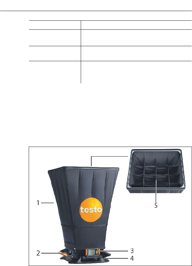
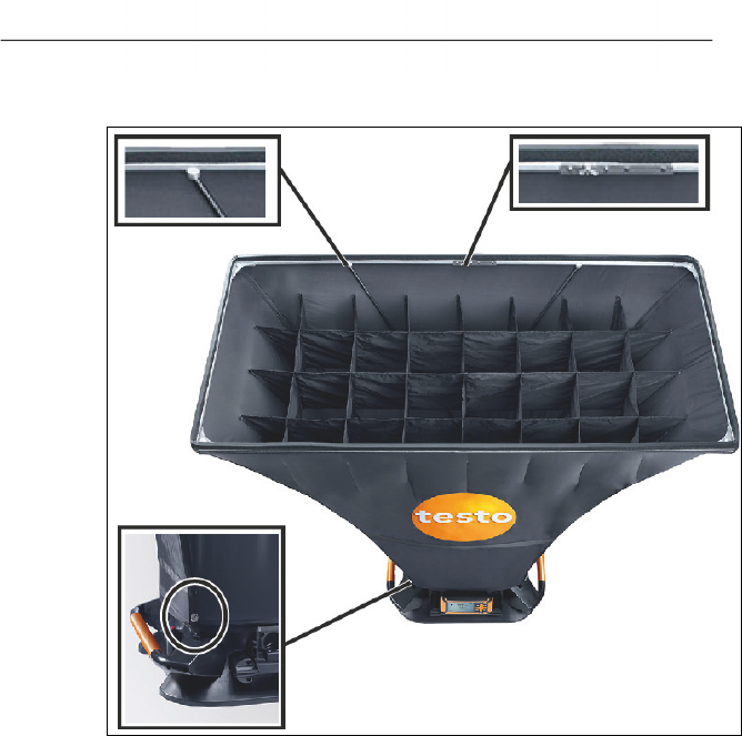
4.1.1. Measurement setup
1 Volume flow hood (standard hood 610x610 mm)
2 Actuator for manual measurement
3 Measuring instrument testo 420
4 Measurement base with differential pressure cross
5 Integrated flow straightener
4 Product description
11
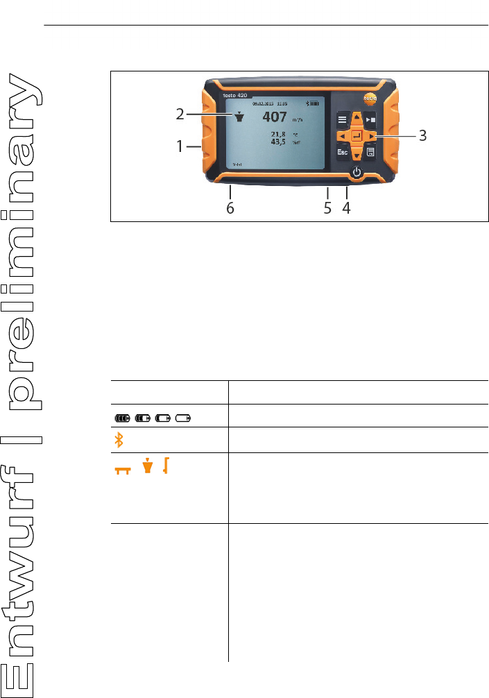
4.1.2. Overview of testo 420
1 Battery compartment, on rear of the instrument
2 Display
3 Control keys
4 Probe socket Mini-DIN
5 Micro-USB port
6 Connection for pressure measurement
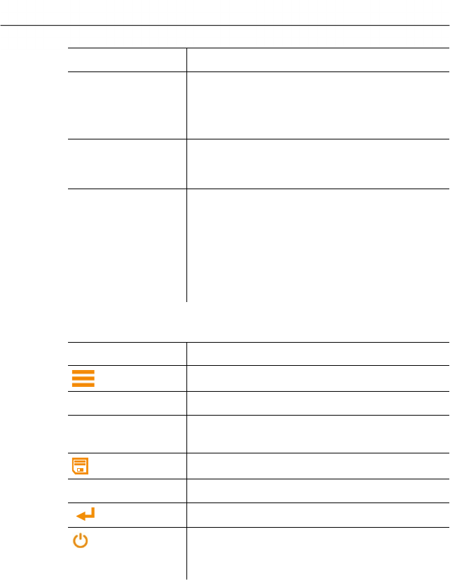
Instrument status icons:
Icon Meaning
Battery capacity
Bluetooth
/ / Measuring mode:
Pressure measurement, Pitot tube, volume
flow (air pressure from above into the hood /
suction outlet)
Actual Actual volume flow:
The current ambient conditions are used to
calculate the volume flow. The actual
barometric pressure is measured with the
internal sensor. In applications with volume
flow hood, the temperature is measured by
the integrated temperature/humidity sensor,
with Pitot tube measurement the actual
temperature needs to be input manually.
4 Product description
12
Icon Meaning
Standard Standard volume flow:
The standard settings for temperature and
barometric pressure (21 °C / 1013 hPa) are
used to calculate the volume flow.
K-factor Factor by which the current reading is
multiplied. Depends on which outlet
measurements are being taken at.
Pitot Tube factor The Pitot tube factor for Pitot tubes is
generally the same and must be entered:
• Pitot tubes from Testo: 1.00
• Pitot tubes from other manufacturers: the
Pitot tube factor can be found in the
instruction manual or you should ask your
supplier.
Control keys
Key Function
Menu
[►, ■] Holds / starts / stops a measurement
[ESC] Switches to the previous view / to the
measurement view
Saves the measured values
[►, ▲, ▼,◄] Navigation within the menu
[ ] Confirms a selection
Switch instrument on/off (press and hold
down)
Switch illumination on/off (press briefly)
5 First steps
13
5 First steps
Inserting batteries/rechargeable batteries
1. Open the battery compartment.
2. Insert the batteries or rechargeable batteries (scope of delivery
includes 4x 1.5V Type AA/ LR6).
3. Close the battery compartment.
When not in use for a long period of time, take the
batteries/rechargeable batteries out.
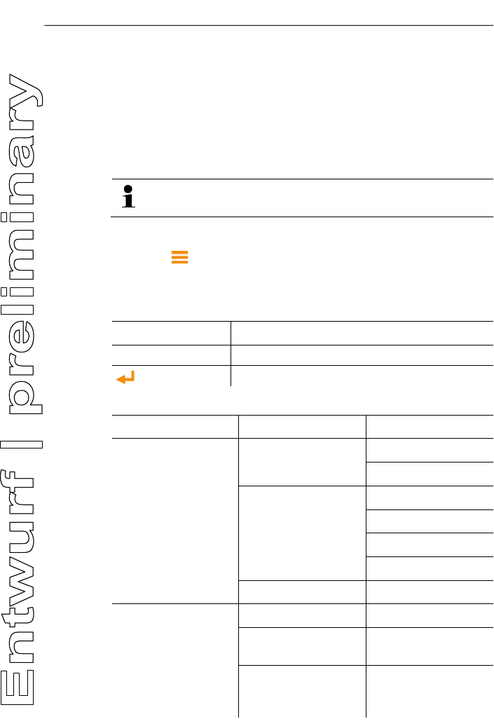
Implementing settings
1. Press to access the menu.
2. Select the menu item you require using ►, ▲, ▼, ◄.
Key functions
Display Explanation
►, ▲, ▼,◄ Change parameter, select unit
Confirm input
1. Menu Level 2. Menu Level 3. Menu Level
Application Flow Hood K-factor
Actual/Standard
Pitot tube Duct
Pitot tube factor
Pitot Temperature
Actual/Standard
Pressure only --
Measuring Program
Single Measurment --
Continous
Measurement
--
Continous/Punctual
measurement (nur für
Staurohr)
measuring duration

5 First steps
14
1. Menu Level 2. Menu Level 3. Menu Level
Memory New Folder --
Folder 1 --
Display Volume Flow on/off
Diff.Pressure on/off
Temperature on/off
Velocity on/off
Humidity on/off
Abs.Pressure on/off
Device Settings Language English/German/Italia
n/French/Spanish
Backlight Auto Off On/Off
Auto Off On/Of
Bluetooth On/Off
Date&Time Date Format
Time Format
Set Date&Time
Gliding average 5 – 20 sec
Hood adjustment Supply Air
Exhaust Air
Zeroing int 1-20 sec
Reset Device -- --
6 Using the product
15
6 Using the product
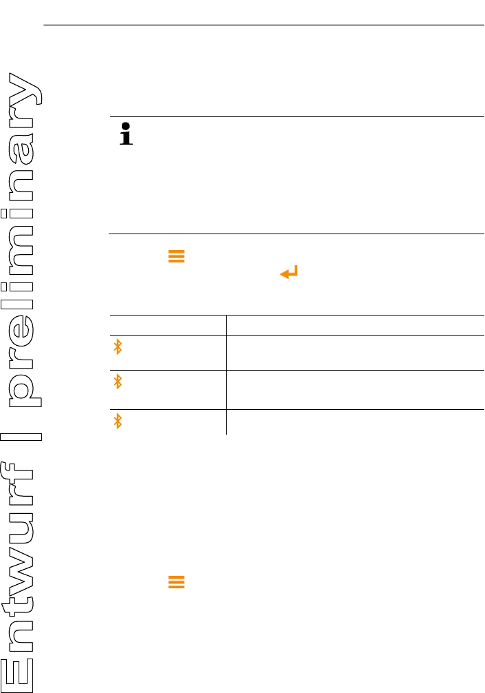
6.1. Switching Bluetooth® on and off
In order to be able to establish a connection via Bluetooth,
you need a tablet or smartphone with the Testo App
Climate already installed on it.
You can get the App for iOS instruments in the App Store
or for Android instruments in the Play Store.
Informa
tion about compatibility can be found in the relevant
App Store.
1. Press -> Device Settings -> Bluetooth, ► and using ▲/▼
-> select Off. Confirm with .
- Once the Bluetooth icon is shown on the display,
Bluetooth is switched on.
Display
Explanation
flashes There is no Bluetooth connection, or a
potential connection is being searched for.
is permanently
displayed
There is a Bluetooth connection.
is not displayed Bluetooth is disabled.
6.2. Settings for the measurement
6.2.1. Damping (gliding average)
If the readings fluctuate widely, it is advisable to damp the
readings. The time range for the damping can be set manually
between 5-20 seconds.
1. Press , then select Device settings and Gliding average.
- The damping can be set between 5-20 seconds.

6 Using the product
16
6.2.2. Hood calibration
This input is provided for the filing of calibration data by the relevant
calibration laboratory. The flow hood-specific adjustment data can
be input manually for supply air and exhaust air and has a direct
effect on the measurement results. Input option of 0.001-9.999.
1. Press , then select Device settings and Hood adjustment.
- Calibration of the hood can be set for supply air and exhaust air.
6.2.3. Zeroing interval (automatic zeroing)
The pressure sensor carries out automatic zeroing at regular
intervals. These intervals can be set via the automatic zeroing.
1. Press , then select Device settings and Zeroing int.
- The zeroing interval can be set between 1-20 seconds.
6 Using the product
17
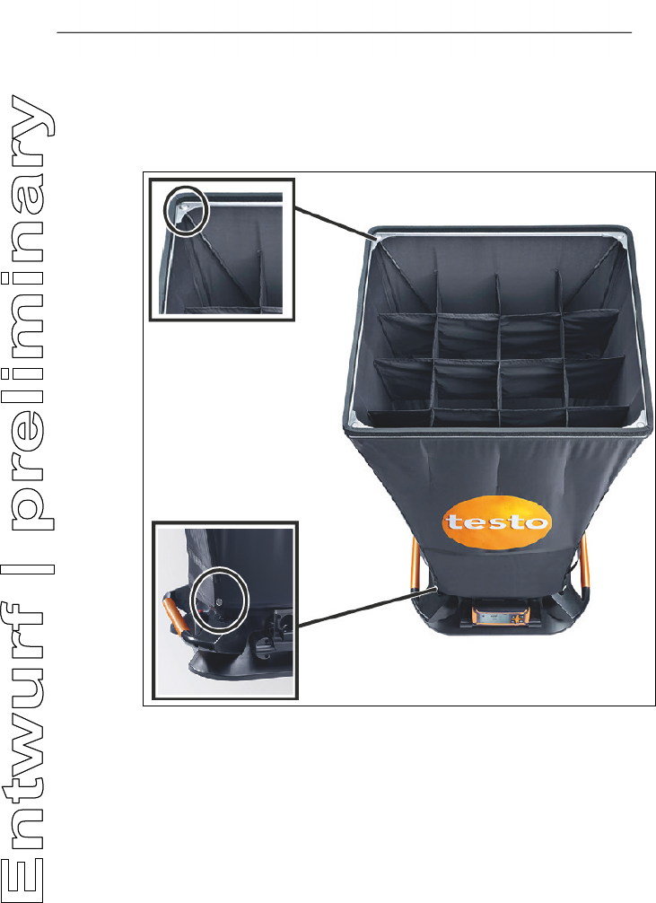
6.3. Volume flow measurement setup
Standard hood
(610x610 mm, scope of delivery; 360x360, accessories)
1. Pull the lower end of the hood over the measurement base.
2. Attach the hood at two corners using the snap fasteners.
3. Tighten the closure.
4. Push the support rods through the hood, along the markings
and into the funnel in the measurement base.
5. Push the support rods on the top of the hood into the brackets.
- The hood is installed.
6 Using the product
18
Large hood
(1220x610 and 1220x305, accessories)
1. Install the aluminium frame and stretch the fabric hood over the
framework, so that the elastic band lies in the recess of the
frame. Make sure that the elastic band fits correctly, especially
at the corners.
2. Pull the lower end of the hood over the measurement base.
3. Attach the hood at two corners using the snap fasteners.
4. Tighten the closure.
5. Push the support rods through the hood, along the markings
and into the funnel in the measurement base.
6. Push the support rods on the top of the hood into the brackets.
- The hood is installed.
6 Using the product
19
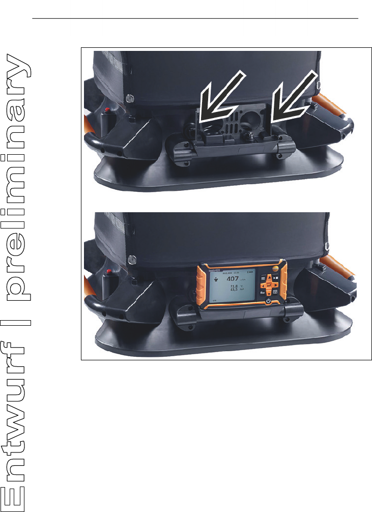
Attaching the measuring instrument
1. Push the testo 420 completely into the instrument holder, pay
attention to the catch on the right-hand and left-hand side in the
bracket.
6 Using the product
20
6.4. Measuring
6.4.1. Volume flow measurement
✓ The volume flow hood is fitted.
1. Switch on the instrument.
2. In the instrument settings, set the application volume flow hood
and also the required measurement program:
Single measurement or Continuous measurement.
3. Press ►, ■ on the testo 420, or the trigger on the measurement
base to hold or start and stop the measurement.
4. Press to save the measurement data. Unsaved
measurement data is lost once you carry out the next
measurement.
- The target folder and file name are displayed, confirm with
to save the measurement data under this name and in the
selected folder.
6.4.2. Pitot tube measurement
1. Remove the testo 420 from the measurement base.
2. Connect the hoses to the testo 420 and to the Pitot tube.
3. Press -> Application -> Pitot tube and there set the duct
geometry, the Pitot tube factor and the temperature, and
choose between actual and standard.
4. Select the required measurement program.
5. Carry out the measurement.
6. Press to save the measurement data. Unsaved
measurement data is lost once you carry out the next
measurement.
- The target folder and file name are displayed, confirm with
to save the measurement data under this name and in the
selected folder.
6.4.3. Differential pressure measurement
1. Remove the testo 420 from the measurement base.
2. Connect the hoses to the testo 420 at + and -.
3. Press -> Application -> Pressure only.
6 Using the product
21
4. Carry out the measurement.
5. Press to save the measurement data. Unsaved
measurement data is lost once you carry out the next
measurement.
- The target folder and file name are displayed, confirm with
to save the measurement data under this name and in the
selected folder.
6.5. Saving
> -> Memory ->
- The folder overview is shown on the display. Create a new
folder via New Folder.
Open folder
> Using the arrow keys, navigate to the required folder and press
.
- The selected folder is opened and the individual files are
displayed.
Delete folder
1. Using the arrow keys, navigate to the required folder and press
.
2. Select the menu item Delete Folder and confirm with .
- The folder that you want to delete is shown on the display.
3. Confirm once again with in order to delete the folder,
or cancel by pressing Esc.
Set as Logging Folder
This setting establishes which folder is to be specified as
the standard storage location for saving the measurements.
1. Using the arrow keys, navigate to the required folder and press
.
2. Select the menu item Set as Logging Folder and confirm with
.
- The selected folder is set as the standard storage location.
- The stored location can be changed during the saving process.
Total Volume Flow
If data from single measurements is saved within a folder,
the total volume flow of all measurements can be displayed
using this function.

8 Tips and assistance
22
1. Using the arrow keys, navigate to the required folder and press
.
2. Select the menu item Total Volume Flow and confirm with .
- The single measurements and the total volume flow are
displayed.
6.6. Transferring measurement data to the PC
1. Connect the testo 420 to your PC using the USB cable.
- The testo 420 switches on automatically, a window appears on
the PC, select Open folder here. The folders and files saved on
your testo 420 are displayed. The files are available in the file
format *.txt.
7 Maintaining the product
7.1. Cleaning the instrument
Do not use any aggressive cleaning agents or solvents!
Mild household cleaning agents or soap suds may be used.
> If the housing of the instrument is dirty, clean it with a damp
cloth.
8 Tips and assistance
8.1. Questions and answers
Question Possible causes/solution
For selected parameters,
no values are shown on
the instrument display
(-----)
No temperature/humidity probe is
connected, for instance.
Warning message
Can not
turn on! when selecting
certain parameters in the
Display menu.
This parameter is not available for the
application currently selected.
8.2. Error messages
Question Possible causes/solution
xx xx

8 Tips and assistance
23
8.3. Accessories and spare parts
Description Article no.
Flow hood 360x360 mm 0554 4200
Flow hood 305x1220 mm 0554 4201
Flow hood 610x1220 mm 0554 4202
Fabric cover for the hood 610x610 0400 4200
Aluminium frame for the hood 610x610 0440 4204
Tripod, extendable to 4 m 0554 4209
Connection hose, silicone, length 5 m,
maximum load capacity 700 hPa (mbar)
0554 0440
Connection hose, silicone-
free, for differential
pressure measurement, length 5 m,
maximum load capacity 700 hPa (mbar)
0554 0453
Pitot tube, length 500 mm, Ø 7 mm, stainless
steel, for measuring flow velocity
(Connection hose required)
0635 2045
Pitot tube, length 350 mm, Ø 7 mm,
stainless steel, for measuring flow velocity
(Connection hose required)
0635 2145
Pitot tube, 1,000 mm long, stainless steel,
measures flow velocity
(Connection hose required)
0635 2345
Connection hose 0554 0453
Tension rod 0440 4201
For a complete list of all accessories and spare parts, please refer
to the product catalogues and brochures or visit our website
www.testo.com
If you have any questions, please contact your dealer or Testo
Customer Service. The contact details can be found on the back of
this document or on the Internet at www.testo.com/service-
contact..

0970 4200 de 01 V01.00
Power is so low that no RF exposure calculation is needed.
FCC statements:
This device complies with part 15 of the FCC rules. Operation is subject to the
following two conditions: (1) this device may not cause harmful interference, and (2)
this device must accept any interference received, including interference that may
cause undesired operation.
NOTE: The manufacturer is not responsible for any radio or TV interference caused
by unauthorized modifications or changes to this equipment. Such modifications or
changes could void the user’s authority to operate the equipment.
NOTE: This equipment has been tested and found to comply with the limits for a
Class B digital device, pursuant to part 15 of the FCC Rules. These limits are designed
to provide reasonable protection against harmful interference in a residential
installation. This equipment generates uses and can radiate radio frequency energy
and, if not installed and used in accordance with the instructions, may cause harmful
interference to radio communications. However, there is no guarantee that
interference will not occur in a particular installation. If this equipment does cause
harmful interference to radio or television reception, which can be determined by
turning the equipment off and on, the user is encouraged to try to correct the
interference by one or more of the following measures:
‐ Reorient or relocate the receiving antenna.
‐ Increase the separation between the equipment and receiver.
‐Connect the equipment into an outlet on a circuit different from that to which the
receiver is connected.
‐Consult the dealer or an experienced radio/TV technician for help.
Federal Communication Commission (FCC) Radiation Exposure Statement
When using the product, maintain a distance of 20cm from the body to
ensure compliance with RF exposure requirements.