Trane Pkgsvx17aen Installation Owner Diagnostic Split System Cooling Condensers CTA 7 1/2 To 15 Tons User Manual D8375ee7 7eed 427a B5cf 9e43c58a113e
User Manual: trane pkgsvx17aen Trane Air Conditioner PKG-SVX17A-EN User Guide |
Open the PDF directly: View PDF ![]() .
.
Page Count: 28
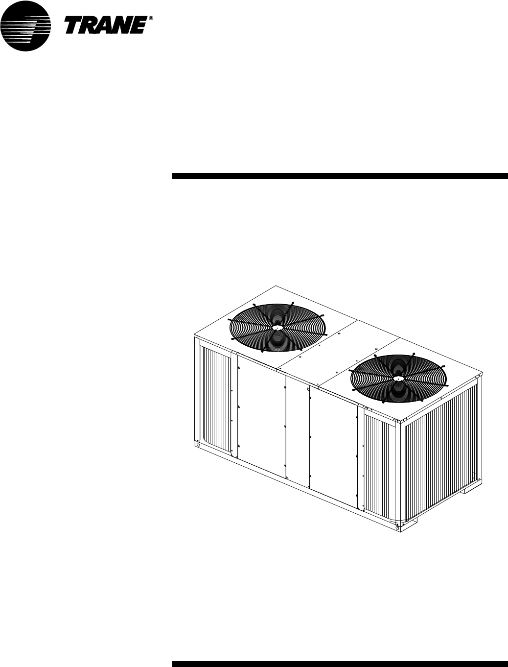
PKG-SVX17A-EN
September 2007
Models
“A” and later Design Sequence
Installation
Owner
Diagnostics
Split System Cooling Condensers
Model CTA 7 1/2 to 15 Tons
CTA
090A***A – 60 HZ
120A***A – 60 HZ
120B***A – 60 HZ
180B***A – 60 HZ
© 2007 American Standard All rights reserved PKG-SVX17A-EN
Notice
Overview of Manual
Note: One copy of this document
ships inside each unit and is customer
property. It must be retained by the
unit’s maintenance personnel.
This booklet describes proper installa-
tion, operation, and maintenance pro-
cedures for air cooled systems. By
carefully reviewing the information
within this manual and following the
instructions, the risk of improper
operation and/or component damage
will be minimized.
It is important that periodic mainte-
nance be performed to help assure
trouble free operation. A maintenance
schedule is provided at the end of this
manual. Should equipment failure
occur, contact a qualified service
organization with qualified, experi-
enced HVAC technicians to properly
diagnose and repair this equipment.
NOTICE:
Warnings and Cautions appear at
appropriate sections throughout this
manual. Read these carefully.
WARNING– Indicates a
potentially hazardous situation
which, if not avoided, could
result in death or serious injury.
CAUTION – Indicates a
potentially hazardous situation
which, if not avoided, may result
in minor or moderate injury. It
may also be used to alert against
unsafe practices.
CAUTION – Indicates a situa-
tion that may result in equipment
or property-damage-only acci-
dents.
IMPORTANT NOTE: All phases of this
installation must comply with the
NATIONAL, STATE & LOCAL CODES.
In addition to local codes, the installa-
tion must conform with National Elec-
tric Code -ANSI/NFPA NO. 70 LATEST
REVISION.
Note: Do Not release refrigerant
to the atmosphere! If adding or
removing refrigerant is required, the
service technician must comply with
all federal, state, and local laws.
PKG-SVX17A-EN 3
Contents
Installation/Startup/Commissioning 4
Model Number Description 4
Unit Dimensions 5
Electrical Data 8
Unit Inspection 9
Initial Leak Test 9
Lifting Recommendations 9
Clearances 10
Unit Mounting 10
Refrigerant Piping 10
Leak Check 12
System Evacuation 12
Refrigeration Charging 12
Electrical Wiring 13
Low Voltage Wiring 14
Refrigeration Schematic 20
Installation Checklist 21
Sequence of Operation 22
Maintenance 23
Warranty 25
4PKG-SVX17A-EN
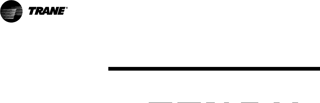
Model Number Description
All products are identified by a multi-
ple-character model number that pre-
cisely identifies a particular type of
unit. An explanation of the alphanu-
meric identification code is provided
below. Its use will enable the owner/
operator, installing contractors, and
service engineers to define the opera-
tion, specific components, and other
options for any specific unit.
When ordering replacement parts or
requesting service, be sure to refer to
the specific model number, serial
number, and DL number (if applica-
ble) stamped on the unit nameplate.
Digits 1,2,3 - Product Type
CTA = Remote Air-Cooled Condenser
Digits 4,5,6 - Nominal Gross
Cooling Capacity (MBh)
090 = 090 MBh-used with
3 & 5T SCRH
120 = 120 MBh - used with
7.5 & 10T SCRH
180 = 180 MBh - used with
12 & 15T SCRH
Digits 7 - Major Development
Sequence
A = 1 Refrig Cir.(3, 5, 7.5T SCRH)
B = 2 Refrig Cir. (10, 12, 15T SCRH)
Digits 8 - Electrical
Characteristics
1 = 208-230/60/1
2 = 460/60/1
8 = 575/60/1
Digits 9,10 - Factory Installed
Options
00 = Packed Stock
0A = Coated Coil
Digits 11 - Minor Design Sequence
A = First
Digits 12 - Service Digit
A = First
Model Number
Description
Split System Condensing Model Nomenclature
C T A 0 9 0 A 1 0 0 A A
1 2 3 4 5 6 7 8 9 10 11 12
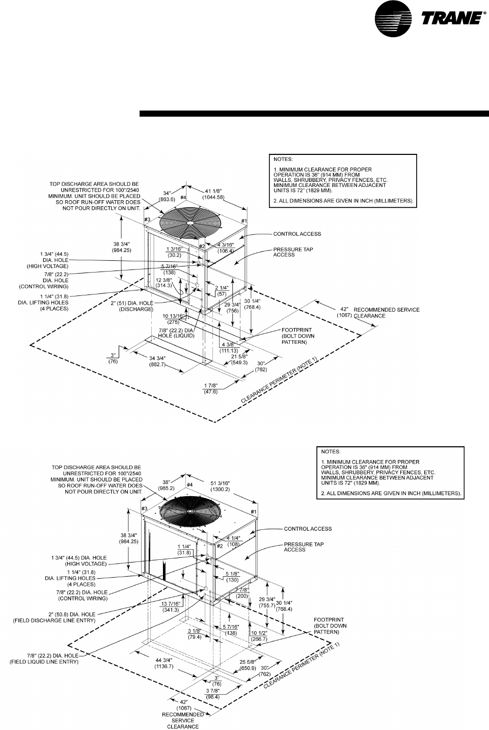
PKG-SVX17A-EN 5
Figure 1 — CTA090A
Figure 2 — CTA120A
Unit
Dimensions
6PKG-SVX17A-EN
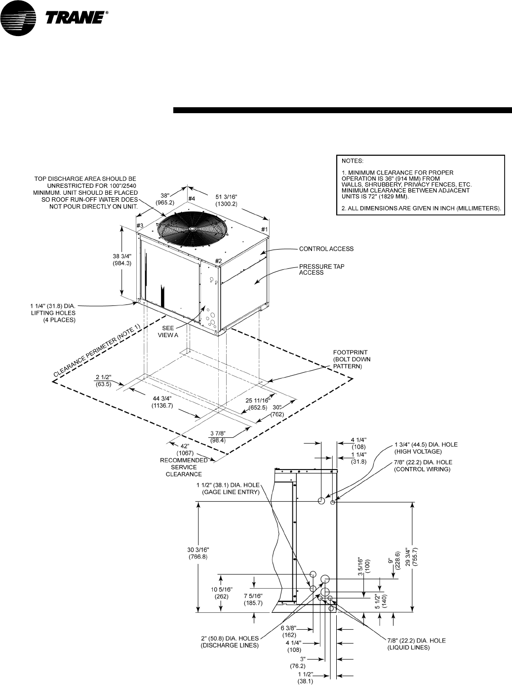
Figure 3 — CTA120B
Unit
Dimensions
PKG-SVX17A-EN 7
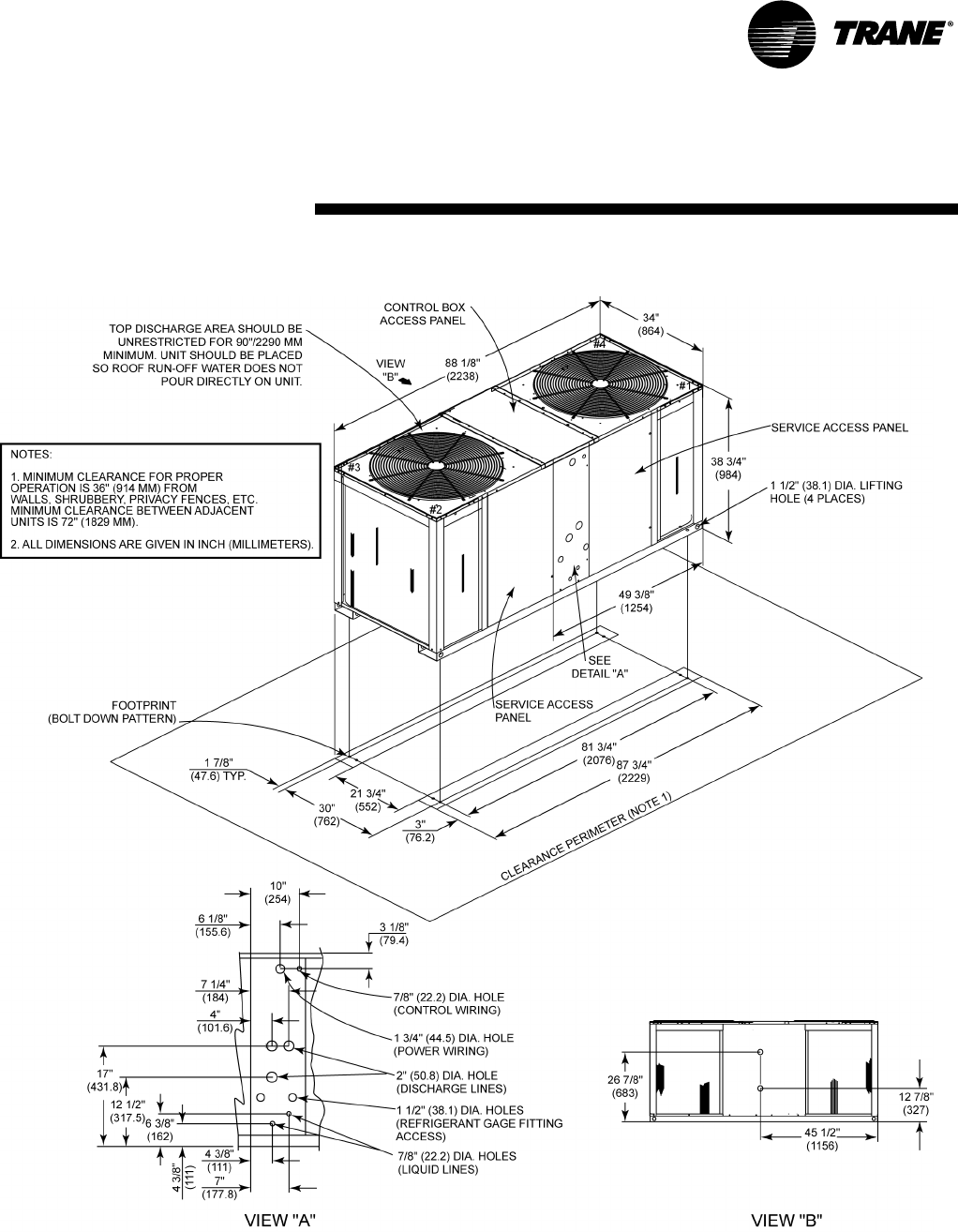
Figure 4 — CTA180B
Unit
Dimensions
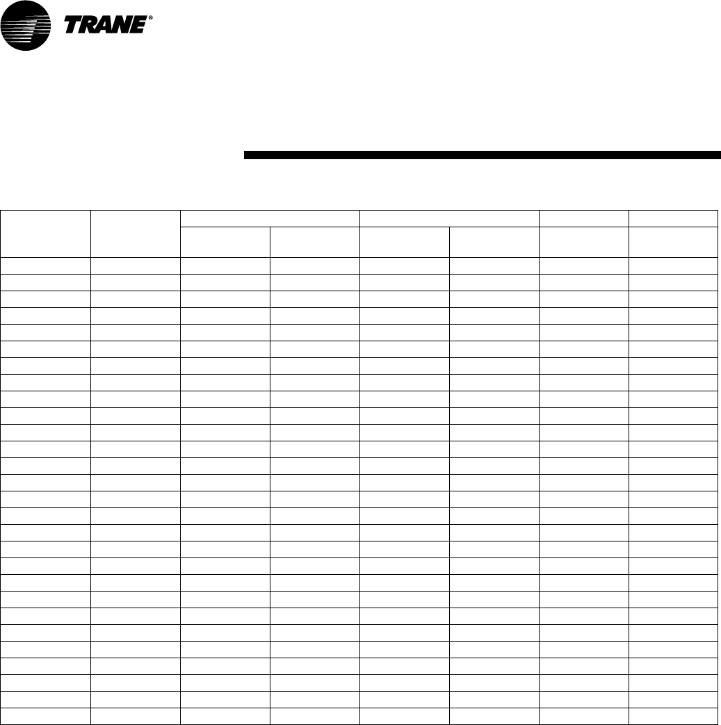
Basic Unit Characteristics Outdoor Fan Motor
Model
Number
Electrical
Characteristics
Allowable
Voltage
Range
Minimum
Circuit
Ampacity
Maximum
Fuse
Size
Qty. HP Amps
FLA
Amps
LRA
CTA090A1 208-230/60/1 187-254 15 15 11/2 3.1 8.1
CTA090A2 460/60/1 414-506 15 15 11/2 1.6 3.7
CTA090A8 575/60/1 518-632 15 15 11/2 1.2 3.0
CTA120A1 208-230/60/1 187-254 15 15 1 1 6.0 17.0
CTA120A2 460/60/1 414-506 15 15 1 1 2.7 7. 0
CTA120A8 575/60/1 518-632 15 15 1 1 2.0 5.7
CTA120B1 208-230/60/1 187-254 15 15 1 1 6.0 17.0
CTA120B2 460/60/1 414-506 15 15 1 1 2.7 7. 0
CTA120B8 575/60/1 518-632 15 15 1 1 2.0 5.7
CTA180B1 208-230/60/1 187-254 15 15 21/2 3.1 8.1
CTA180B2 460/60/1 414-506 15 15 21/2 1.6 3.7
CTA180B8 575/60/1 518-632 15 15 21/2 1.2 3.0
8PKG-SVX17A-EN
Table 1: CTA Unit Electrical Data
Electrical
Data
PKG-SVX17A-EN 9
Installation procedures should be per-
formed in the sequence that they
appear in this manual. Do not destroy
or remove the manual from the unit.
The manual should remain weather-
protected with the unit until all instal-
lation procedures are complete.
Note: It is not the intention of this
manual to cover all possible varia-
tions in systems that may occur or to
provide comprehensive information
concerning every possible contin-
gency that may be encountered dur-
ing an installation. If additional
information is required or if specific
problems arise that are not fully dis-
cussed in this manual, contact your
local Sales office.
Note: “Warnings” and “Cautions”
appear at appropriate
places in this manual. Your personal
safety and the proper
operation of this machine require that
you follow them carefully. The Com-
pany assumes no liability for installa-
tions or servicing performed by
unqualified personnel.
Installation Checklist
An “Installation Checklist” is provided
at the end of the installation section of
this manual. Use the checklist to verify
that all necessary installation proce-
dures have been completed. Do not
use the checklist as a substitute for
reading the information contained in
the manual. Read the entire manual
before beginning installation proce-
dures.
Unit Inspection
Inspect material carefully for any ship-
ping damage. If damaged, it must be
reported to, and claims made against
the transportation company. Compare
the information that
appears on the unit nameplate with
ordering and submittal
data to insure the proper unit was
shipped. Available power supply must
be compatible with electrical charac-
teristics specified on component
nameplates. Replace damaged parts
with authorized parts only.
Inspection Checklist
To protect against loss due to damage
incurred in transit, complete the fol-
lowing checklist upon receipt of the
unit.
[ ] Inspect individual pieces of the
shipment before accepting the unit.
Check for obvious damage to the
unit or packing material.
[ ] Inspect the unit for concealed dam-
age before it is stored and as soon
as possible after delivery. Con-
cealed damage must be reported
within 15 days. If concealed dam-
age is discovered, stop unpacking
the shipment. Do not remove dam-
aged material from the receiving
location. Take photos of the dam-
age if possible. The owner must
provide reasonable evidence that
the damage did not occur after
delivery.
[ ] Notify the carrier’s terminal of dam-
age immediately by phone and by
mail. Request an immediate joint
inspection of the damage by the
carrier and the consignee.
[ ] Notify the sales representative and
arrange for repair. Do not repair the
unit until the damage is inspected
by the carrier’s representative.
Initial Leak Test
All CTA units are shipped with a hold-
ing charge of nitrogen in each circuit.
Remove the service access panel(s)
shown in Figures 1 to 4. Locate the
discharge or liquid line gauge ports
for each circuit. Install gauges to
determine if the circuits are still pres-
surized. If not, the charge has
escaped. Repair as required to obtain
a leak-free circuit.
Lifting Recommendations
Before preparing the unit for lifting,
estimate the approximate center of
gravity for lifting safety. Because of
placement of internal components,
the unit weight may be unevenly dis-
tributed. Approximate unit weights
are given in Table 2.
Model Ship
Max.
Net
Max.
Corner Weights
#1 #2 #3 #4
CTA090A 254 210 59 63 39 49
CTA120A 325 281 62 85 57 77
CTA120B
CTA180B 532 447 100 105 124 118
Table 2: Unit and corner weights (lbs)
WARNING
Heavy Objects!
Do not use cables (chains or
slings) except as shown. Each of
the cables (chains or slings) used
to lift the unit must be capable of
supporting the entire weight of
the unit. Lifting cables (chains or
slings) may not be of the same
length. Adjust as necessary for
even unit lift. Other lifting
arrangements may cause equip-
ment or property-only damage.
Failure to properly lift unit could
result in death or serious injury.
See details below.
The crated unit can be moved using a
forklift of suitable capacity. For lifting
the unit, attach lifting straps or slings
securely to the lifting holes at each
corner. Use spreader bars to protect
the unit casing from damage. Test lift
the unit to determine proper balance
and stability.
CAUTION
Equipment Damage!
Use spreader bars to prevent lift-
ing straps from damaging the
unit. Install bars between lifting
straps. Failure to properly lift unit
may result in crushing unit cabi-
net or damaging unit finish.
Installation
10 PKG-SVX17A-EN
Clearances
Provide enough space around the unit
to allow unrestricted access to all ser-
vice points. Refer to Figure 1 through
Figure 4 for unit dimensions and mini-
mum required service and free air
clearances. Observe the following
points to insure proper unit operation.
A. Do not install the unit under a low
overhang. Condenser discharge must
not be restricted. See Notes in Figure
1 through Figure 4.
NOTICE: Do not obstruct condenser
discharge air. This can result in warm
air recirculation through the coil.
B. Do not locate the unit in a position
where runoff water can fall into the
fan discharge openings.
C. Condenser intake air is supplied
from three or four sides of the unit.
Adhere to the minimum required
clearances given in Figure 1 through
Figure 4.
Unit Mounting
Rooftop Mounting: If the unit will be
roof mounted, determine for certain
that the structure is strong enough to
support the unit and any required
accessories. Unit weights are given in
Table 2. The unit should be elevated
on a level, field fabricated four-inch
steel or wood 4" x 4" mounting frame.
Complete the frame and secure it into
position before lifting the unit to the
roof. The mounting frame must sup-
port a minimum of three of the unit’s
four sides and should span roof sup-
ports to distribute the load on the
roof.
Figure 5 Roof Mounted Unit
WARNING
Structural Failure!
Ensure that the roof structure
supports are strong enough to
support the weight of the unit
and any accessories. Failure to do
this could result in death or seri-
ous injury due to structural fail-
ure and could seriously damage
the unit and the building.
Ground Level Mounting
“For ground level installation, the unit
base should be adequately supported
and hold the unit near level. The
installation must meet the guidelines
set forth in local codes.” The support
should extend two inches beyond the
unit base channels at all points. The
unit and support must be isolated
from any adjacent structure to prevent
possible noise or vibration problems.
Any ground level location must com-
ply with required clearances given in
Figure 1 through Figure 4.
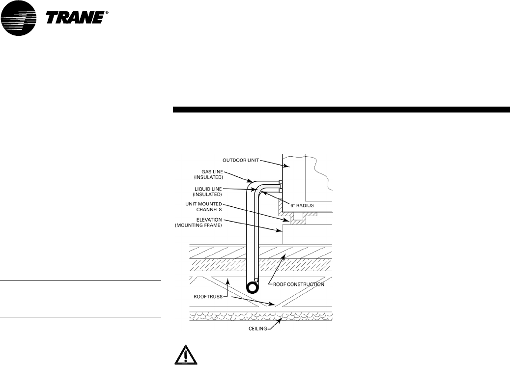
Holes must be made in the structure
to run refrigerant lines. For the major-
ity of ground-level installations, the
holes can be made in the header that
rests on top of the foundation. Alter-
natively, these holes may also be
made in the foundation itself. On roof-
mounted units, refrigerant lines
should enter the building as close to
the unit as possible; preferably within
three to four inches of the refrigerant
connection on the unit, plus a six-inch
(long radius) 90 degree "L" entering
the building (See Figure 5).
Refrigerant Piping Guidelines
A. Maximum recommended line
lengths: (per circuit)
Maximum linear length..............200 Ft.
(w/o accumulator)
Maximum discharge line lift......200 Ft.
Maximum liquid line lift..............60 Ft.
B. Maximum allowable pressure
drops (R-410A):
Discharge line...............................10 psi
Liquid line (without subcooler)...50 psi
Route refrigerant piping for minimum
linear length, minimum number of
bends and fittings (no reducers) and
minimum amount of line exposed to
outdoor ambients.
C. Recommended line sizes:
CTA090, 120A (single circuit)
CTA120B, 180B (dual circuit)
Discharge line - 7/8 inch sealed type L
refrigerant tubing.
Liquid line - 1/2 inch sealed type L
refrigerant tubing.
Installation
PKG-SVX17A-EN 11
Note: Insulate all refrigerant piping
and connections.
Refrigerant Piping Procedures
(Outdoor Units)
Each CTA unit ships with a holding
charge of dry nitrogen. The nitrogen
should be removed and the entire sys-
tem evacuated (at the proper time) to
avoid possible contamination.
1. Remove the service access panel.
2. Locate the liquid and discharge
lines. Check that the piping connec-
tion stubs on the valves (Figure 6)
line up properly with the holes in
the unit cabinet.
Figure 6
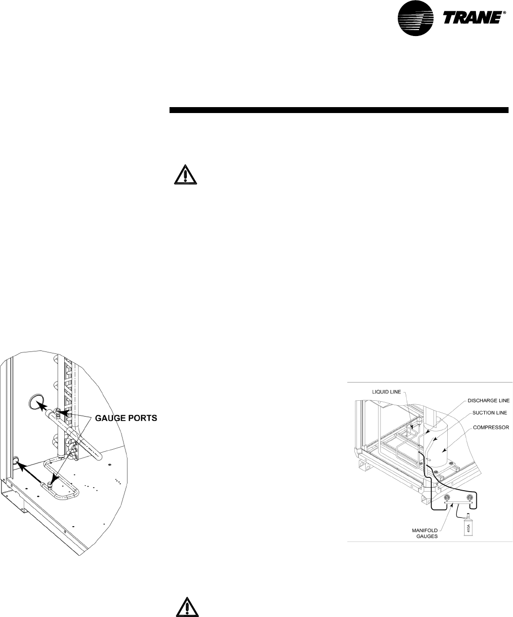
3. Locate the gauge ports on the dis-
charge and liquid lines. Depress the
valve core to release the nitrogen
from the unit.
Note: If nitrogen is not released from
the unit, there is a leak in the system.
Locate the leak and repair before pro-
ceeding with the installation.
4. Unbraze the tube seal caps to reveal
the line braze connections.
WARNING:
Hazardous Pressures!
Coil has a nitrogen holding
charge. Do not remove seal caps
by heating the caps while coil is
under pressure. Depress the
gauge port valve cores to gradu-
ally relieve nitrogen holding
charge. Remove valve cores
before removing the tubing seal
caps. Failure to properly relieve
pressure could result in death or
serious injury.
CAUTION:
Equipment Damage!
Do not remove the seal caps from
refrigerant connections until pre-
pared to braze refrigerant lines to
the connections. Excessive expo-
sure to atmosphere may allow
moisture or dirt to contaminate
the system, damaging valve seals
and causing ice formation in sys-
tem components.
5. Cut, fit and braze tubing, starting at
the outdoor unit and work toward
the indoor unit.
Note: Use long radius bells for all 90
degree bends.
All brazing should be done using a 2
to 3 psig dry nitrogen purge flowing
through the pipe being brazed (Figure
6).
WARNING:
Hazardous Pressures!
When using dry nitrogen cylin-
ders for pressurizing units for
leak testing, always provide a
pressure regulator on the cylinder
to prevent excessively high unit
pressures. Never pressurize unit
above the maximum recom-
mended unit test pressure as
specified in applicable unit litera-
ture. Failure to properly regulate
pressure could result in a violent
explosion, which could result in
death or serious injury or equip-
ment or property-only-damage.
CAUTION:
Equipment Damage!
Wet-wrap all valves and protect
painted surfaces from excessive
heat. Heat can damage system
components and the unit finish.
6. Shut off nitrogen supply.
7. Shut off the manifold valve for the
line that is connected to the dis-
charge line gauge port.
Figure 7
Refrigerant Piping Procedure
(Indoor Unit)
Once liquid and discharge lines are
complete to the refrigerant connec-
tions on the indoor unit, depress the
gauge port valve cores on the suction
and discharge lines to gradually
relieve nitrogen holding charge.
Installation
12 PKG-SVX17A-EN
WARNING:
Hazardous Pressures!
Coil has a nitrogen holding
charge. Do not remove seal caps
by heating the caps while coil is
under pressure. Depress the
gauge port valve cores to gradu-
ally relieve nitrogen holding
charge. Remove valve cores
before removing the tubing seal
caps. Failure to properly relieve
pressure could result in death or
serious injury.
1. Remove both seal caps from the
indoor unit connection stubs.
CAUTION:
Equipment Damage!
Do not remove the seal caps from
refrigerant connections until pre-
pared to braze refrigerant lines to
the connections. Excessive expo-
sure to atmosphere may allow
moisture or dirt to contaminate
the system, damaging valve seals
and causing ice formation in sys-
tem components.
2. Turn nitrogen supply on. Nitrogen
enters through liquid line gauge
port.
WARNING:
Hazard of Explosion and Deadly
Gases!
Never solder, braze or weld on
refrigerant lines or any unit com-
ponents that are above atmo-
spheric pressure or where
refrigerant may be present.
Always remove refrigerant by fol-
lowing the guidelines estab-
lished by the EPA Federal Clean
Air Act or other state or local
codes as appropriate. After refrig-
erant removal, use dry nitrogen to
bring system back to atmospheric
pressure before opening system
for repairs. Mixtures of refriger-
ants and air under pressure may
become combustible in the pres-
ence of an ignition source leading
to an explosion. Excessive heat
from soldering, brazing or weld-
ing with refrigerant vapors
present can form highly toxic
gases and extremely corrosive
acids. Failure to follow all proper
safe refrigerant handling prac-
tices could result in death or seri-
ous injury.
3. Braze the liquid line connections.
4. Open the gauge port on the dis-
charge line and then braze the dis-
charge line to the connection stub.
Nitrogen will bleed out the open
gauge port on the discharge line.
5. Shut off nitrogen supply.
Leak Check
After the brazing operation of the out-
door and indoor refrigerant lines is
complete, check the field brazed con-
nections for leaks. Pressurize the sys-
tem through the gauge port with dry
nitrogen to 200 psi. Use soap bubbles
or other leak-checking methods to
ensure that all field joints are leak
free. If not, release pressure, repair
and repeat the leak test.
System Evacuation
1. After completion of leak check,
replace suction, liquid and dis-
charge valve cores, and evacuate
the system.
2. Attach appropriate hoses from the
manifold gauge to suction and dis-
charge line gauge ports.
Note: Unnecessary switching of hoses
can be avoided and complete evacua-
tion of lines leading to a sealed sys-
tem can be accomplished with
manifold center hose and connecting
branch hose to cylinder of R-410A and
vacuum pump.
3. Attach center hose of manifold
gauges to the vacuum pump.
4. Evacuate the system to hold a 350
micron vacuum.
5. Close off the valve to the vacuum
pump and observe the micron
gauge. If gauge pressure rises
above 500 microns in one (1)
minute, evacuation is incomplete or
the system has a leak.
6. If vacuum gauge does not rise
above 500 microns in one (1)
minute, the evacuation should be
complete.
7. With vacuum pump and micron
gauge blanked off, open the valve
on R-410A cylinder and allow refrig-
erant pressure to build up to 100
psig.
8. Close valve on the R-410A supply
cylinder. Close valves on the mani-
fold gauge. Set and remove the
refrigerant charging hoses from the
discharge and suction gauge ports.
9. Leak test the entire system. Using
proper procedures and caution,
repair any leaks found and repeat
the leak test.
Refrigerant Charging Procedure
If charging by weight, refer to refriger-
ant charges that are provided in Table
3. If additional refrigerant is needed
because of length of line, calculate the
requirements using Table 4. Charge
by weight through the gauge port on
the suction line in the indoor unit.
When charging is complete, replace
the cap on the gauge port.
Insulating and Isolating
Refrigerant Lines
Insulate the entire discharge line with
refrigerant piping insulation. Also
insulate any portion of the liquid line
exposed to temperature extremes.
Insulate and isolate liquid and dis-
charge lines from each other. Isolate
refrigerant lines from the structure
and any ductwork.
Note: To prevent possible noise or
vibration, be certain to isolate refriger-
ant lines from the building.
Installation
PKG-SVX17A-EN 13
Table 3: CTA Refrigerant Charge
Model Refrigerant Charge
(R-410A)*
CTA090A
w/SCRH030 18.1 lbs
CTA090A
w/SCRH050 19.9 lbs
CTA120A
w/SCRH075 20.8 lbs
CTA120B
w/SCRH100
11.9 lbs
(Ckt. #1 & #2)
CTA180B
w/SCRH120
16.8 lbs. (Ckt. #1)
16.0 lbs. (Ckt. #2)
CTA180B
w/SCRH150
17.5 lbs. (Ckt. #1)
16.9 lbs. (Ckt. #2)
* Sufficient operating charge for listed unit
and 33 feet of nominally sized refrigerant
piping.
Table 4: Additional Refrigerant
Tubing Sizes Additional
Tubing
Length
Additional
Refrig.
Discharge Liquid
7/8" 1/2" 15 ft. 1.3 l bs
7/8" 1/2" 25 ft. 2.2 lbs
7/8" 1/2" 32 ft. 2.8 lbs
7/8" 1/2" 40 ft. 3.5 lbs
Note: Amounts shown are based on 0.087
lbs of refrigerant per foot of 7/8" and 1/2"
lines.
Note: For tubing over 40 feet, calculate
the additional refrigerant needed,
based on notes above.
Gaseous Charging
This procedure is accomplished with
the unit operating. Electrical connec-
tions must be complete. Do not pro-
ceed until the system is ready to
operate.
Procedure
1. Connect R-410A drum with gauge
manifold to the gauge ports (pres-
sure taps) on the compressor dis-
charge and suction lines (Figure 7).
Note: On the CTA units, the service
access panel must be installed when
the unit is running and being charged.
WARNING:
Hazardous Energy Sources!
Use extreme caution while servic-
ing the unit when the control box
access panel is removed and
power is applied to the unit. Fail-
ure to observe all safety precau-
tions could result in death or
serious injury.
2. Turn on power to the unit. Allow the
system to run for five to ten minutes
to stabilize operating conditions.
3. Measure airflow across the indoor
coil. Compare the measurements
with the fan performance data in the
Data/Submittal.
4. Check suction line superheat and
condenser sub-cooling to ensure
the unit is operating properly.
5. Disconnect all power to the unit.
WARNING:
Hazardous Voltage
w/Capacitors!
Disconnect all electrical power,
including remote disconnects and
discharge all motor start/run ca-
pacitors before servicing. Follow
proper lockout/tagout procedures
to ensure the power cannot be in-
advertently energized. Verify with
an appropriate voltmeter that all
capacitors have discharged. Fail-
ure to diconnect power and dis-
charge capacitors before
servicing could result in death or
serious injury.
Note: For additional information
regarding the safe discharge of
capacitors, see PROD-SVB06A-EN
or PROD-SVB06A-FR.
6. Remove the charging system from
the unit and replace all access pan-
els.
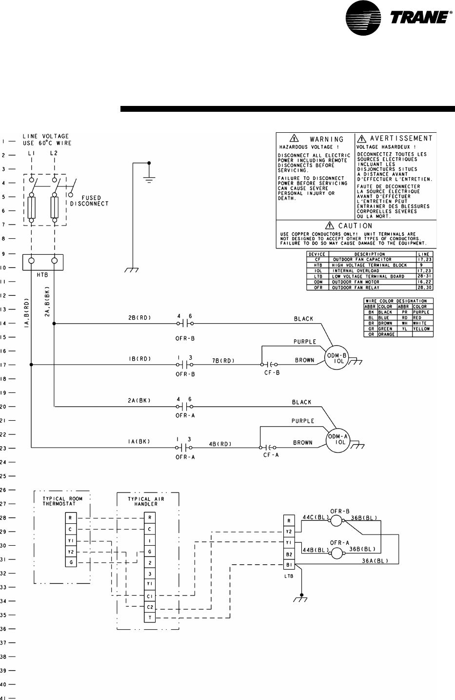
Electrical Wiring
CTA field wiring consists of providing
power supply to the unit, installing the
system indoor thermostat and provid-
ing low voltage system interconnect-
ing wiring. Access to electrical
connection locations is shown in Fig-
ures 1 through 4.
Unit Power Supply
The installer must provide line voltage
circuit(s) to the unit main power termi-
nals as shown by the unit wiring dia-
grams in Figures 9 and 10 on page 15.
Power supply must include a discon-
nect switch in a location convenient to
the unit. Ground the unit according to
local codes and provide flexible con-
duit if codes require and/or if vibration
transmission may cause noise prob-
lems.
CAUTION:
Use Copper Conductors Only!
Unit terminals are not designed to
accept other types of conductors.
Failure to use copper conductors
may result in equipment damage.
CAUTION:
All wiring must comply with appli-
cable local and national NEC
codes. Type and location of dis-
connect switches must comply
with all applicable codes.
WARNING:
Ground Wire!
All field-installed wiring must be
completed by qualified personnel.
All field-installed wiring must
comply with NEC and applicable
local codes. Failure to follow this
instruction could result in death
or serious injuries.
WARNING:
Grounding Required!
Follow proper local and state elec-
trical code on requirements for
grounding. Failure to follow code
could result in death or serious in-
jury
Installation
14 PKG-SVX17A-EN
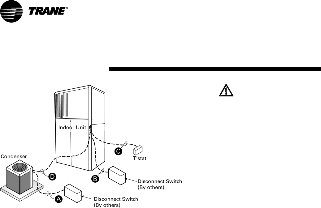
Note:
1. Wiring shown with dashed lines is to
be furnished and installed by the cus-
tomer. All customer supplied wiring
must be copper only and must con-
form to NEC and local electrical codes.
Codes may require line of sight be-
tween disconnect switch and unit.
CTA090A/S(C,I)RH030
CTA090A/S(C,I)RH050
CTA120A/S(C,I)RH075
CTA120B/S(C,I)RH100
Field Wiring:
A — 2 power wires. Line voltage for
single phase
B — 3 power wires. Line voltage for
3 phase; 2 wires for single phase
C — Cooling only thermostat: 3 wires,
24 volts.
— Digital thermostat: add 1 addi-
tional wire, 24 volts.
D — 2 control wires, 24 volts.
CTA180B/S(C,I)RH120
CTA180B/S(C,I)RH150
Field Wiring:
A — 2 power wires. Line voltage for
single phase
B — 3 power wires. Line voltage for
3 phase
C — Cooling only thermostat: 4 wires,
24 volts.
D — 3 control wires, 24 volts.
WARNING:
Hazardous Voltage w/Capacitors!
Disconnect all electrical power,
including remote disconnects and
discharge all motor start/run ca-
pacitors before servicing. Follow
proper lockout/tagout procedures
to ensure the power cannot be in-
advertently energized. Verify with
an appropriate voltmeter that all
capacitors have discharged. Fail-
ure to diconnect power and dis-
charge capacitors before
servicing could result in death or
serious injury.
Note: For additional information
regarding the safe discharge of
capacitors, see PROD-SVB06A-EN
or PROD-SVB06A-FR.
Determine proper wire sizes and unit
protective fusing requirements by
referring to the unit nameplate. Field
wiring diagrams for accessories
are shipped with the accessory.
Wiring
Low Voltage
Figure 8: Typical Field Wiring
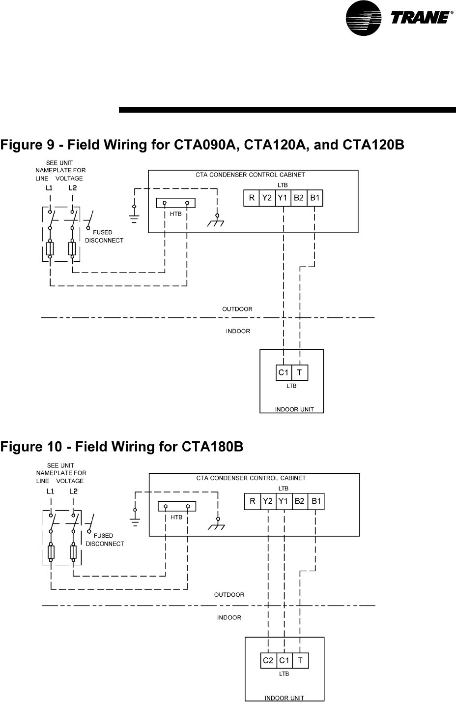
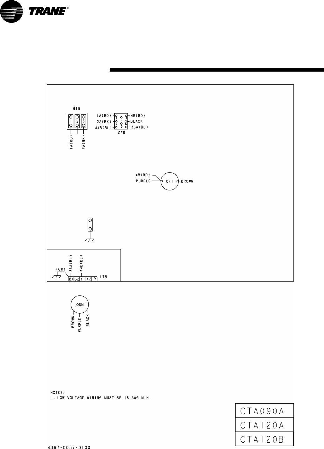
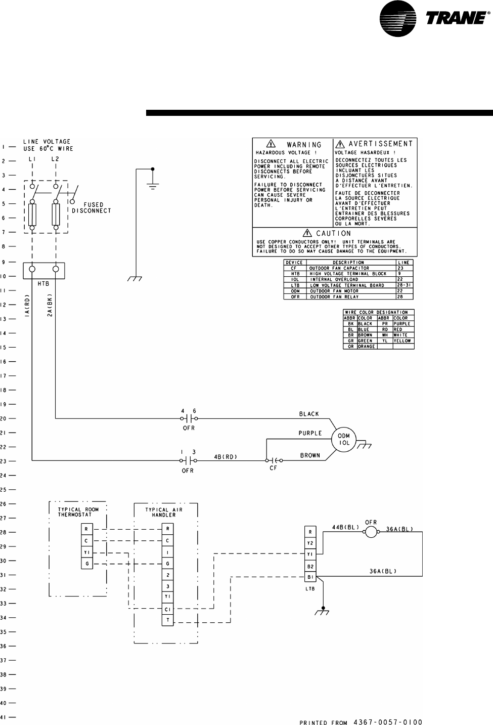
PKG-SVX17A-EN 15
Field Wiring
16 PKG-SVX17A-EN
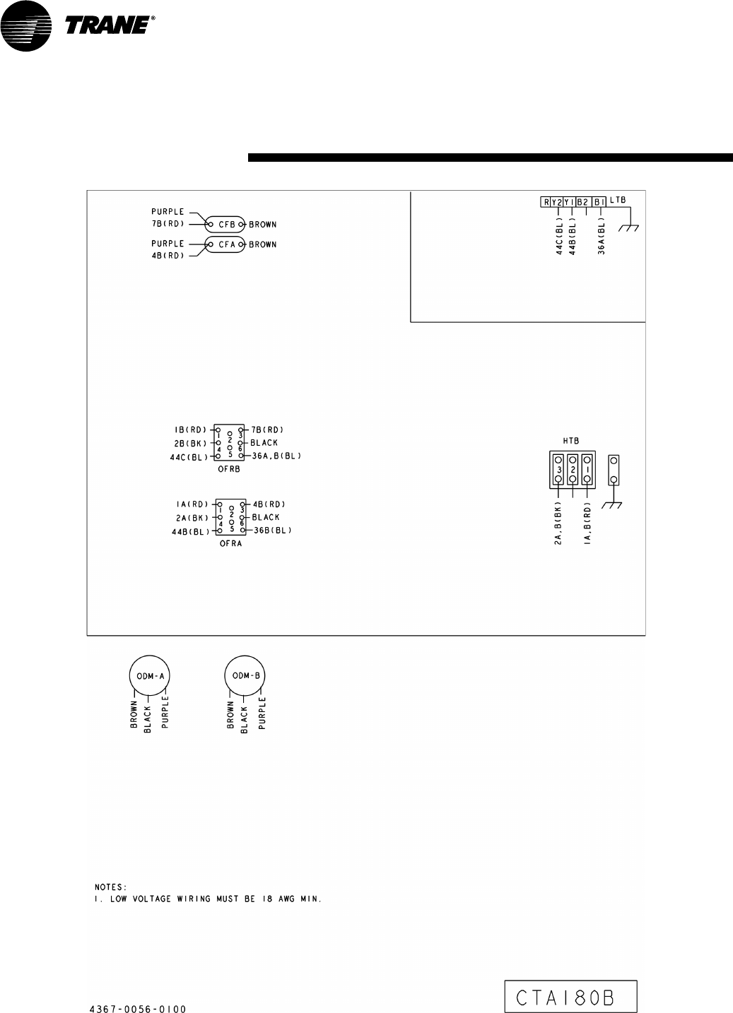
Wiring
PKG-SVX17A-EN 17
Wiring
18 PKG-SVX17A-EN
Wiring
PKG-SVX17A-EN 19
Wiring
20 PKG-SVX17A-EN
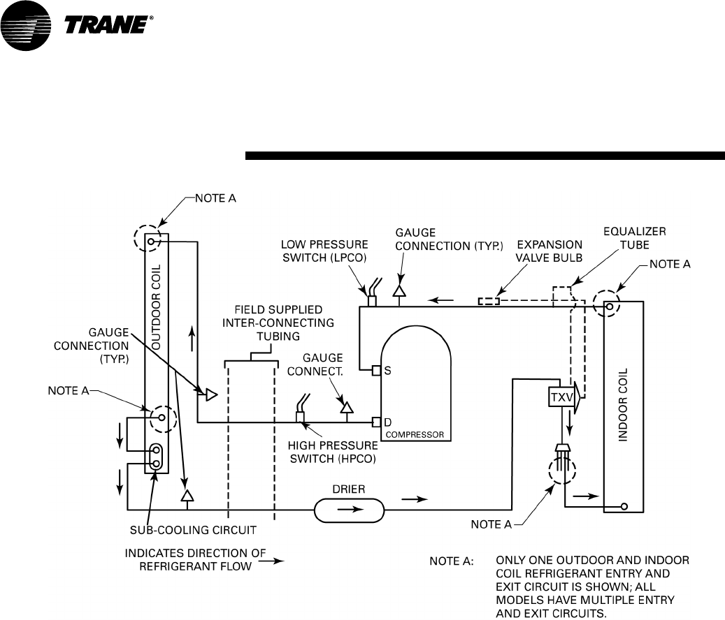
Refrigeration
Diagram
Figure 11: Typical Split System Cooling Diagram
PKG-SVX17A-EN 21
Installation Checklist
Complete this checklist once the unit
is installed to verify that all recom-
mended procedures have been
accomplished before starting the sys-
tem. Do not operate the system until
all items covered by this checklist are
complete.
[ ] Inspect unit location for proper
required service clearances.
[ ] Inspect unit location for proper free
air clearances.
[ ] Inspect unit location for secure,
level mounting position.
Refrigerant Piping
[ ] Performed initial leak test?
[ ] Connected properly sized and con-
structed liquid and discharge lines
to the connection stubs at both the
indoor and outdoor units?
[ ] Insulated the entire discharge line?
[ ] Insulated portions of liquid line
exposed to extremes in tempera-
ture?
[ ] Evacuated each refrigerant circuit
to 350 microns?
[ ] Charged each circuit with proper
amount of R-410A?
Electrical Wiring
WARNING:
Hazardous Voltage
w/Capacitors!
Disconnect all electrical power,
including remote disconnects and
discharge all motor start/run ca-
pacitors before servicing. Follow
proper lockout/tagout procedures
to ensure the power cannot be in-
advertently energized. Verify with
an appropriate voltmeter that all
capacitors have discharged. Fail-
ure to diconnect power and dis-
charge capacitors before
servicing could result in death or
serious injury.
Note: For additional information
regarding the safe discharge of
capacitors, see PROD-SVB06A-
EN or PROD-SVB06A-FR.
[ ] Provided unit power wiring (with
disconnect) to proper terminals in
the unit control section?
[ ] Installed system indoor thermo-
stat?
[ ] Installed system low voltage inter-
connecting wiring to proper termi-
nals of outdoor unit, indoor unit
and system thermostat?
System
Pre-Start Procedure
22 PKG-SVX17A-EN
Unit Start-Up
Once the unit is properly installed and
pre-start procedures
are complete, start the unit by turning
the System Switch on the indoor ther-
mostat to either HEAT, COOL or AUTO.
The system should operate normally.
Sequence of Operation
General
Operation of the system cooling (and
optional heating) cycles is controlled
by the position of the system switch
on the room thermostat. Once the
system switch is placed in either the
HEAT or COOL position, unit opera-
tion is automatic. The optional auto-
matic changeover thermostat, when
in the AUTO position, automatically
changes to heat or cool with sufficient
room temperature change.
Evaporator Fan (Indoor Supply
Air)
The evaporator fan is controlled by an
ON/AUTO switch on the room ther-
mostat. With the switch positioned at
AUTO and the system operating in
the cooling mode, fan operation coin-
cides with the cooling run cycles. If
the system is equipped with heat and
is operating in the heating mode
while the fan switch is at AUTO, fan
operation coincides with the heating
run cycles. When the fan switch is
positioned at ON, fan operation is
continuous.
Cooling Mode
When the room thermostat system
switch is positioned at COOL and the
fan switch is at AUTO, the condenser
fan relay energizes on a call for cool-
ing. When the contacts of the con-
denser fan relay close, operation of
the condenser fan begins. The evapo-
rator fan contactor also energizes on a
call for cooling and initiates evapora-
tor fan operation.
On units with dual circuits, the second
stage of cooling is initiated as a result
of the 2-stage thermostat calling for
additional cooling.
System
Pre-Start Procedure
PKG-SVX17A-EN 23
WARNING:
Hazardous Service Procedures!
The maintenance and trouble-
shooting procedures recommend-
ed in this section of the manual
could result in exposure to electri-
cal, mechanical or other potential
safety hazards. Always refer to
the safety warnings provided
throughout this manual concern-
ing these procedures. When possi-
ble, disconnect all electrical
power including remote discon-
nects before servicing. Follow
proper lockout/tagout procedures
to ensure the power can not be in-
advertently energized. When nec-
essary to work with live electrical
components, have a qualified li-
censed electrician or other indi-
vidual who has been trained in
handling live electrical compo-
nents perform these tasks. Failure
to follow all of the recommended
safety warnings provided, could
result in death or serious injury.
Maintenance
Perform all of the indicated mainte-
nance procedures at the
intervals scheduled. This will prolong
the life of the unit and reduce the pos-
sibility of costly equipment failure.
Monthly
Conduct the following maintenance
inspections once per month.
WARNING:
Hazardous Voltage w/Capacitors!
Disconnect all electrical power,
including remote disconnects and
discharge all motor start/run ca-
pacitors before servicing. Follow
proper lockout/tagout procedures
to ensure the power cannot be in-
advertently energized. Verify with
an appropriate voltmeter that all
capacitors have discharged. Fail-
ure to diconnect power and dis-
charge capacitors before
servicing could result in death or
serious injury.
Note: For additional information
regarding the safe discharge of
capacitors, see PROD-SVB06A-EN
or PROD-SVB06A-FR.
1. Inspect air filters and clean if neces-
sary.
2. Check unit wiring to ensure all con-
nections are tight and that the wir-
ing insulation is intact.
3. Check drain pans and condensate
piping to insure they are free of ob-
stacles.
4. Manually rotate the indoor fan to in-
sure proper operation.
5. Inspect the evaporator and con-
denser coils for dirt and debris. If the
coils appear dirty, clean them.
6. With the unit operating in the cool-
ing mode, check the suction and dis-
charge pressures. Record these
readings on the “Maintenance
Log.”
7. Observe indoor fan operation and
correct any unusual or excessive vi-
bration. Clean blower wheels as
needed.
Annually (Cooling Season)
The following maintenance proce-
dures must be performed at the begin-
ning of each cooling season to insure
efficient unit operation.
1. Perform all of the monthly mainte-
nance inspections.
2. With the unit operating, check unit
superheat and record the reading in
the Maintenance Log.
3. Remove any accumulation of dust
and/or dirt from the unit casing.
4. Remove corrosion from any surface
and repaint. Check the gasket
around the control panel door to in-
sure it fits correctly and is in good
condition to prevent water leakage.
5. Inspect the evaporator fan belt. If it
is worn or frayed, replace it.
6. Inspect the control panel wiring to
insure that all connections are tight
and that the insulation is intact.
7. Check refrigerant piping and fittings
for leaks.
Maintenance
Date
Ambient
Te m p .
F
Evaporator Entering Air Compressor Superheat Subcooling
Dry Bulb Wet Bulb Suction
Pressure
Discharge
Pressure Circuit #1 (F) Circuit #1 (F)
24 PKG-SVX17A-EN
Maintenance Log
Note: Perform each inspection once per month (during cooling season) while unit is operating.
Maintenance
PKG-SVX17A-EN 25
Warranty Information
Standard Warranty
The standard split system cooling condenser warranty is Trane’s parts-
only warranty, running 12-months from startup, not to exceed 18-
months from shipment.
Extended Warranty
The optional extended warranty is a second through fifth year warranty.
The time starts at the end of standard 1-year coverage through the fifth
year.
These extended warranties apply only to new equipment installed in do-
mestic Trane Commercial Systems Group sales territories and must be
ordered prior to start-up.
Warranty
CTA
Trane has a policy of continuous product and product data improvement and reserves the right to
change design and specifications without notice.
Literature Order Number PKG-SVX17A-EN
Date September 2007
Supersedes SS-SVN11A-EN October 2004
Trane
A business of American Standard Companies
www.trane.com
For more information, contact your local Trane
office or e-mail us at comfort@trane.com
