u blox Malmo 000501 Bluetooth Serial Module User Manual users manual
u-blox Malmo AB Bluetooth Serial Module users manual
UserManual.wiki
>
u blox Malmo
>
000501 User Manual
users manual
Navigation menu
Upload a User Manual
Namespaces
Wiki Guide
HTML
PDF
Info
Views
User Manual
Discussion / Help
Navigation
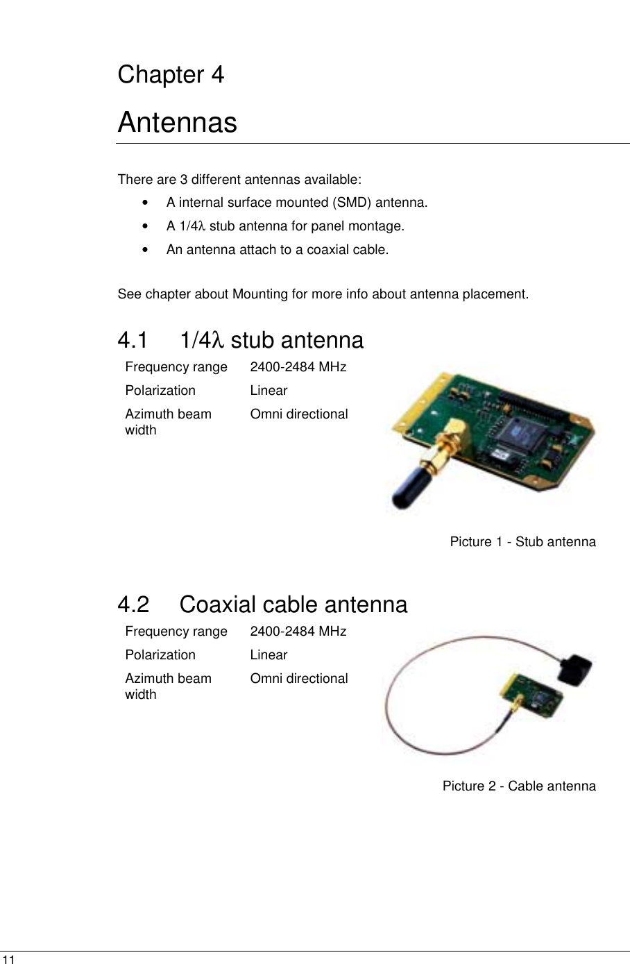
![14 Chapter 6 Mechanics 6.1 Board outlines The main board is 65.0x40.0x1.6mm excluding the mounting wings. The wings are electrical isolated and can for example be mounted in the mounting rails of a metal enclosure. The wings can be removed by V-Cuts. Figure 2 - Board outlines [mm]. Mounting wing, can be removed by V-Cut Mounting wing, can be removed by V-Cut 65.000 5.500 5.500 40.000 36.000 2 x R 2.00030.000](https://usermanual.wiki/u-blox-Malmo/000501/User-Guide-180555-Page-14.png)
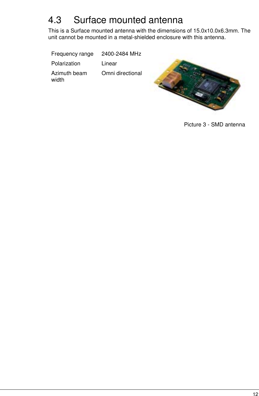
![15 6.2 Mounting holes There are 3 mounting holes on the main board and 3 on each mounting wing. Figure 3 - Mounting holes [mm]. 2 x ∅2.500 – Conductive mounting hole connected to chassi GND 71.000 28.000 ∅2.500 – Isolated mounting hole6 x ∅3.000 – Isolated mounting hole34.000 0.50024.000 54.500 2.500 3.000](https://usermanual.wiki/u-blox-Malmo/000501/User-Guide-180555-Page-15.png)
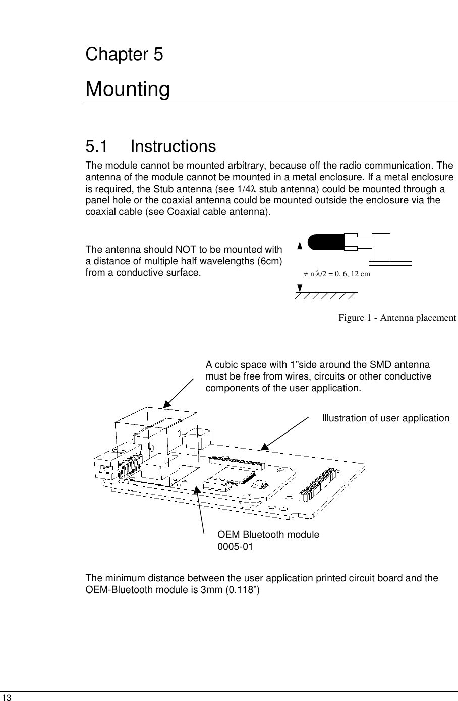
![16 6.3 Component placements and dimensions Components of important are the electrical interface (2x20 1.27mm header list) and the antenna. There are 3 kinds of antennas (see Antennas) but only one is surface mounted. The height of the components is max 3.0mm on the bottom side and 3.5mm on the topside except the antennas (see Figure 4). Figure 4 - Connectors and component heights [mm]. 6.4 Weight With internal antenna: 18g With antenna stub: 24g With antenna on a cable: 39g Mounting wings can be removed by V-Cut 24.600 23.000 10.500 10.000 6.400 6.300 1.600 1 2 39 40 40.400 34.400 27.000 4.30032.400 2.500 – Max panel thickness2x20 1.270 pin socket for interfacing the module. Bottom and top entry 10.000x15.000 SMD Antenna, not mounted if another antenna is used. SMA connector mounted if a ¼ λ antenna or cable antenna is used. ∅6.500 – Panel hole ¼ λ antenna Secondary side, max component height 3.000 Primary side, max component height 3.500 except antenna.SMD antenna, only one of the antennas is mounted. SMA connector for ¼ λ antenna or cable antenna, only one of the antennas is mounted.](https://usermanual.wiki/u-blox-Malmo/000501/User-Guide-180555-Page-16.png)