u blox Malmo 000501 Bluetooth Serial Module User Manual users manual
u-blox Malmo AB Bluetooth Serial Module users manual
users manual
INDUSTRIAL BLUETOOTH™
OEM Serial Port Adapter™/
OEM Bluetooth Enabler™
Electrical & Mechanical Datasheet
OEM Serial Port Adapter™/
OEM Bluetooth Enabler™
Electrical & Mechanical Datasheet

Copyright © 2001 connectBlue AB.
The contents of this document can be changed by connectBlue AB without prior
notice and do not constitute any binding undertakings from connectBlue AB.
connectBlue AB is not responsible under any circumstances for direct, indirect,
unexpected damage or consequent damage that is caused by this document.
All rights reserved.
Release: 0110
Document version: (1.2)
Document number: cBProduct-0108-08
Printed in Sweden.
Trademarks
Registered trademarks from other companies are:Bluetooth is a trademark
owned by the Bluetooth SIG,Inc.Microsoft ™,Windows ™,Windows NT
™,Windows 2000 ™, Windows CE ™,Windows ME ™,are registered
trademarks from Microsoft Corporation.
Part of the software embedded in this product is eCos -Embedded Configurable
Operating System, a trademark of Red Hat. Portions created by Red Hat are
Copyright (C) 1998,1999,2000 Red Hat,Inc.(http://www.redhat.com/).All Rights
Reserved.

4
Contents
1. Introduction 5
1.1 Block diagram.................................................................................... 5
2. Electrical Interface 6
2.1 PCM and I2C connection................................................................... 6
2.2 General Purpose I/O ......................................................................... 7
2.3 UART-communication ....................................................................... 8
RS232 level UART-communication............................................... 8
Logic level UART-communication................................................. 8
Power connection.......................................................................... 9
3. Bluetooth Information 10
3.1 Overview ....................................................................................... 10
4. Antennas 11
4.1 1/4λ stub antenna............................................................................ 11
4.2 Coaxial cable antenna..................................................................... 11
4.3 Surface mounted antenna............................................................... 12
5. Mounting 13
5.1 Instructions...................................................................................... 13
6. Mechanics 14
6.1 Board outlines ................................................................................. 14
6.2 Mounting holes ................................................................................ 15
6.3 Component placements and dimensions........................................ 16
6.4 Weight ....................................................................................... 16
7. Regulatory Information 17
7.1 Declaration of Conformity................................................................ 17
7.2 FCC ....................................................................................... 17
FCC Statement............................................................................ 17
Labeling Requirements for End Product ..................................... 18
Antenna ....................................................................................... 18
5
Chapter 1
Introduction
This Electrical and Mechanical datasheet contains information about the OEM Serial
Port Adapter and the OEM Bluetooth Enabler. Key features:
• Serial interface RS232 or TTL levels
• Power supply 3.6-6.5 V DC.
• Current consumption: 110mA
• Dimensions 40x65mm
• 3 pins for LEDS indication
• 3 pins for buttons
• 4 pins for PCM coded audio
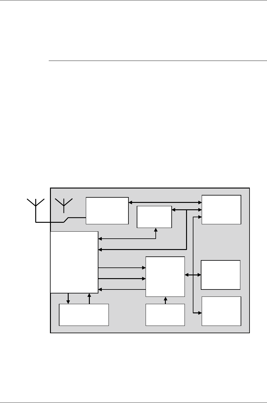
1.1 Block diagram
CPU
RAM
512 kB
FLASH
1 MB
Osc.
Dual
UART
Bluetooth
module
40-pin connector
Power
management
I/O for LEDs
HCI
I/O for buttons
I/O for mode
RS232
driver
RS232 levels
0/3.3V levels
3.3V 5V
Electrical interface
A
ntenna SMD Antenna
(
o
p
tion
)

6
Chapter 2
Electrical Interface
The electrical interface of the module is a 2x20 1.27mm micro header list (female).
The header list is bottom or top entry. Suited male pin lists are for example available
at Samtec (SMD: FW-20-03-F-D-118-162, through hole: FW-20-04-F-D-118-162,
min stacker height, 0.118").
There are some positions reserved for future use. See Components placement and
dimensions for pin placement.
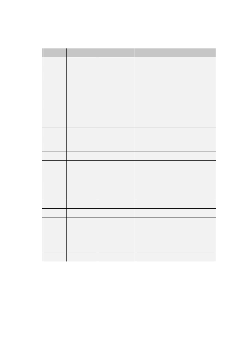
2.1 PCM and I2C connection
These pins are directly connected to the on-board Bluetooth unit.
* Pull-up internal
Pin nr. Pin Name Type Description
1 PCM_CLK
In/Out 100kΩ pull-up* to 3.3V, connected to the
Bluetooth module PCM interface. Only
applicable for OEM Bluetooth Enabler. NC
for OEM Serial Port Adapter.
2 PCM_SYNC
In/Out 100kΩ pull-up* to 3.3V, connected to the
Bluetooth module PCM interface. Only
applicable for OEM Bluetooth Enabler. NC
for OEM Serial Port Adapter.
3 PCM_OUT
Output 100kΩ pull-up* to 3.3V, connected to the
Bluetooth module PCM interface. Only
applicable for OEM Bluetooth Enabler. NC
for OEM Serial Port Adapter.
4 PCM_IN
Input 100kΩ pull-up* to 3.3V, connected to the
Bluetooth module PCM interface. Only
applicable for OEM Bluetooth Enabler. NC
for OEM Serial Port Adapter.
5 I2C_CLK Output Reserved for future use.
6 I2C_DATA In/Out Reserved for future use.
Table 1 - PCM and I2C connections.
7
2.2 General Purpose I/O
All General Purpose Input and Output are logic level 0V – 3.3V.
Use VSS as low-level reference and VCC_3V3 as high-level reference.
Maximum load on all GPIO is 2mA.
* Pull-up internal.
Pin nr. Pin Name Type Description
9 Mode 1
GPIO
10kΩ pull-up* to 3.3V, reserved for
future use
10 Mode 0
GPIO
10kΩ pull-up* to 3.3V. The level on
this pin during power up
selects RS-232(H) or logic(L) level
UART-communication
11 Reset
Open collector
10kΩ pull-up* to 3.3V. Pulled low
by internal reset logic during power
up. External logic can pull this pin
low to reset module.
12 Firq
GPIO
10kΩ pull-up* to 3.3V, reserved for
future use
19 P8 GPIO Reserved for future use
20 P7 GPIO Reserved for future use
21 P6
GPIO
Input for switch_0.
3.3V = switch is open, 0V = switch
is closed
22 P5 GPIO Reserved for future use
23 P4 GPIO Reserved for future use
24 P3 GPIO Reserved for future use
25 RXD1 GPIO Reserved for future use
26 TXD1 GPIO Reserved for future use
27 SCK1 GPIO Reserved for future use
28 B-LED GPIO Output for blue LED driver
29 R-LED GPIO Output for red LED driver
30 G-LED GPIO Output for green LED driver
Table 2 – I/O-pins
8
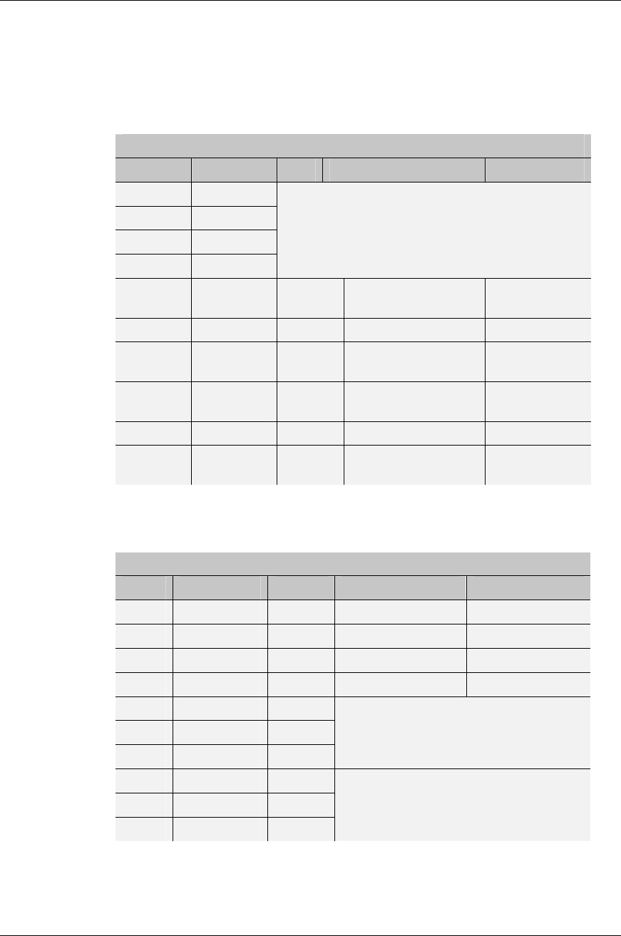
2.3 UART-communication
The “Mode 0” pin (see General Purpose I/O) selects if the UART-communication is
with RS232 levels or logic level. “Mode 0” cannot be changed during operation.
RS232 level UART-communication
Mode 0 = H during power up, RS232 level UART-communication selected.
Pin nr. Pin Name Type Description Level
14 CTSA
15 RXA
13 RTSA
16 TXA
Do NOT connect these pins.
When UART-communication with RS232 signal
levels is enabled this signals are used internally.
RS232 is enabled when Mode 0 (J1 pin nr: 10) is
left open or held high during power up.
33 RS232-
DSR Input Data Set Ready RS232
34 RS232-RX Input Receive data RS232
37 RS232-
CTS Input Clear To Send RS232
35 RS232-
RTS Output Request to Send RS232
36 RS232-TX Output Transmit data RS232
38 RS232-
DTR Output Data Terminal Ready RS232
Logic level UART-communication
Mode 0 = L during power up, Logic level UART-communication selected.
Pin nr. Pin Name Type Description Level
14 CTSA Input Clear To Send 0V/3,3V
15 RXA Input Receive data 0V/3,3V
13 RTSA Output Request to Send 0V/3,3V
16 TXA Output Transmit data 0V/3,3V
33 RS232-DSR Input
34 RS232-RX Input
37 RS232-CTS Input
Inputs accepts RS232 voltage levels but
are internally disconnected from the
UART when UART-communication with
logic level is enabled
35 RS232-RTS Output
36 RS232-TX Output
38 RS232-DTR Output
Although output drivers are active
specific output levels can not be
guaranteed when UART-communication
with logic level is enabled

9
Power connection
Pin nr. Pin Name Type Description
7, 8, 17, 31,
32 VSS
I/O-signal
return path Internal signal ground, separated
from module power ground with
filter.
18 VCC_3V3
Output Internal regulated supply voltage,
Max load 10mA.
39 +5V
Power Module power supply voltage 3.6 –
6.5V, max current consumption
110mA.
40 0V Power Module power ground.
-
CHGND
Power
Two 2.5mm plated mounting holes,
connected to filter center tap for
EMI suppression (see Mounting
holes).

10
Chapter 3
Bluetooth Information
3.1 Overview
In the table below you find information about Bluetooth.
Bluetooth module Ericsson ROK 101 107
RF Output power class 2, min –2dBm type 1.5dBm max +4dBm
Receive sensitive level -70dBm (0.1% BER)
Output frequency 2.4 –2.5 GHz, ISM band.
Point to multi-point operation Yes, OEM Bluetooth Enabler
No, OEM Serial Port Adapter
Bluetooth stack HCI, L2CAP, RFCOMM, SDP and profiles
Bluetooth qualification 1.1*
* in progress.
11
Chapter 4
Antennas
There are 3 different antennas available:
• A internal surface mounted (SMD) antenna.
• A 1/4λ stub antenna for panel montage.
• An antenna attach to a coaxial cable.
See chapter about Mounting for more info about antenna placement.
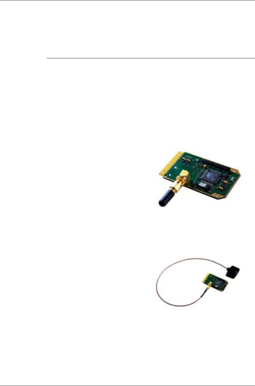
4.1 1/4λ stub antenna
Frequency range 2400-2484 MHz
Polarization Linear
Azimuth beam
width Omni directional
Picture 1 - Stub antenna
4.2 Coaxial cable antenna
Frequency range 2400-2484 MHz
Polarization Linear
Azimuth beam
width Omni directional
Picture 2 - Cable antenna
12
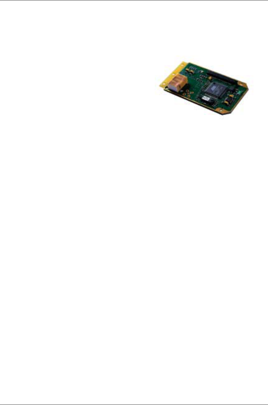
4.3 Surface mounted antenna
This is a Surface mounted antenna with the dimensions of 15.0x10.0x6.3mm. The
unit cannot be mounted in a metal-shielded enclosure with this antenna.
Frequency range 2400-2484 MHz
Polarization Linear
Azimuth beam
width Omni directional
Picture 3 - SMD antenna
13
Chapter 5
Mounting
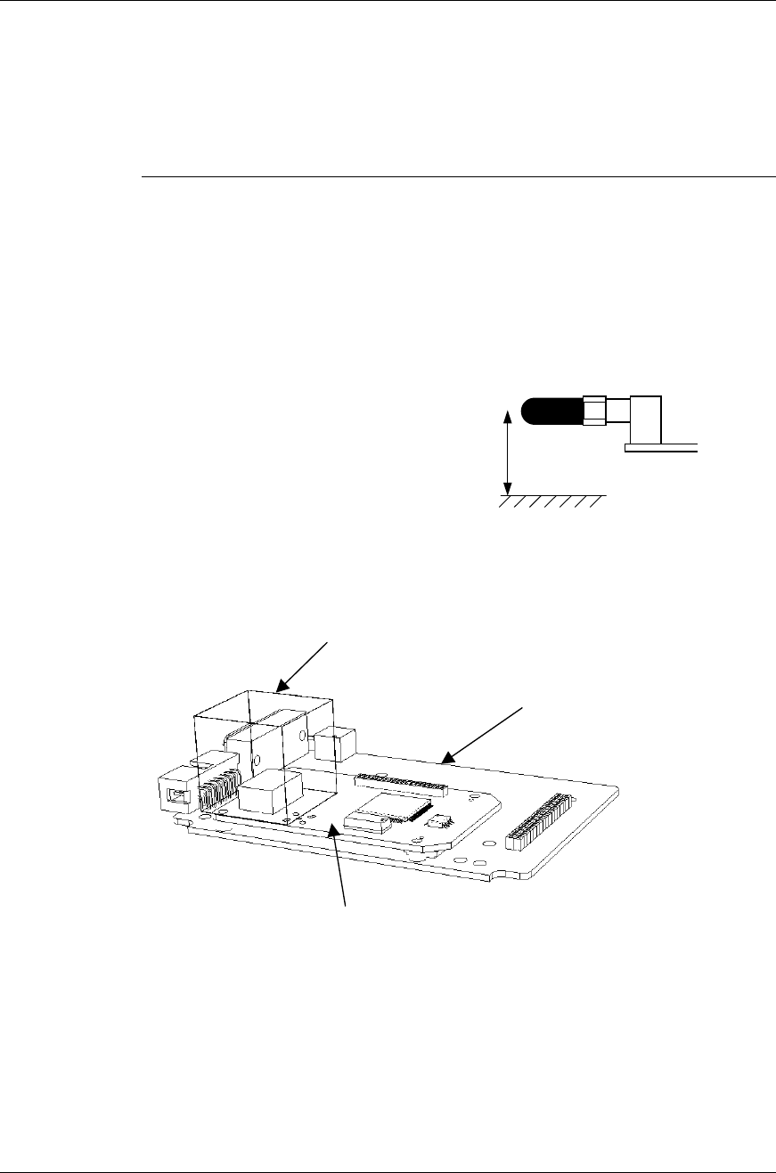
5.1 Instructions
The module cannot be mounted arbitrary, because off the radio communication. The
antenna of the module cannot be mounted in a metal enclosure. If a metal enclosure
is required, the Stub antenna (see 1/4λ stub antenna) could be mounted through a
panel hole or the coaxial antenna could be mounted outside the enclosure via the
coaxial cable (see Coaxial cable antenna).
The antenna should NOT to be mounted with
a distance of multiple half wavelengths (6cm)
from a conductive surface.
Figure 1 - Antenna placement
The minimum distance between the user application printed circuit board and the
OEM-Bluetooth module is 3mm (0.118”)
≠
n
⋅
λ
/2 = 0
,
6
,
12 cm
A
cubic space with 1”side around the SMD antenna
must be free from wires, circuits or other conductive
components of the user application.
Illustration of user application
OEM Bluetooth module
0005-01
14
Chapter 6
Mechanics
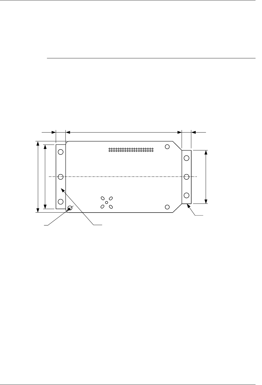
6.1 Board outlines
The main board is 65.0x40.0x1.6mm excluding the mounting wings. The wings are
electrical isolated and can for example be mounted in the mounting rails of a metal
enclosure. The wings can be removed by V-Cuts.
Figure 2 - Board outlines [mm].
Mounting wing, can be removed
by V-Cut
Mounting wing, can be removed
by V-Cut
65.000 5.500 5.500
40.000
36.000
2 x R 2.000
30.000
15
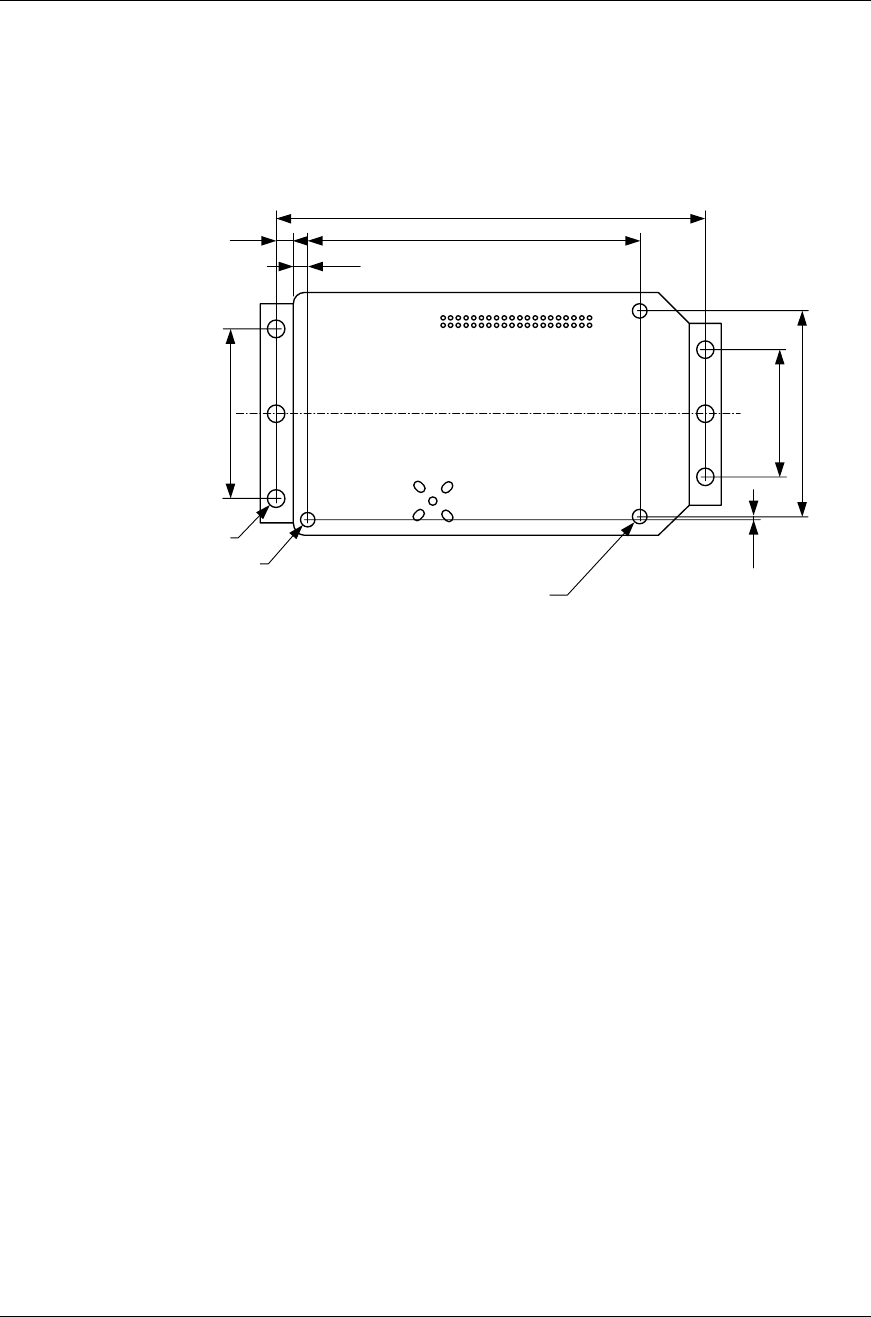
6.2 Mounting holes
There are 3 mounting holes on the main board and 3 on each mounting wing.
Figure 3 - Mounting holes [mm].
2 x ∅2.500 – Conductive mounting
hole connected to chassi GND
71.000
28.000
∅2.500 – Isolated mounting hole
6 x ∅3.000 – Isolated mounting hole
34.000
0.500
24.000
54.500
2.500
3.000
16
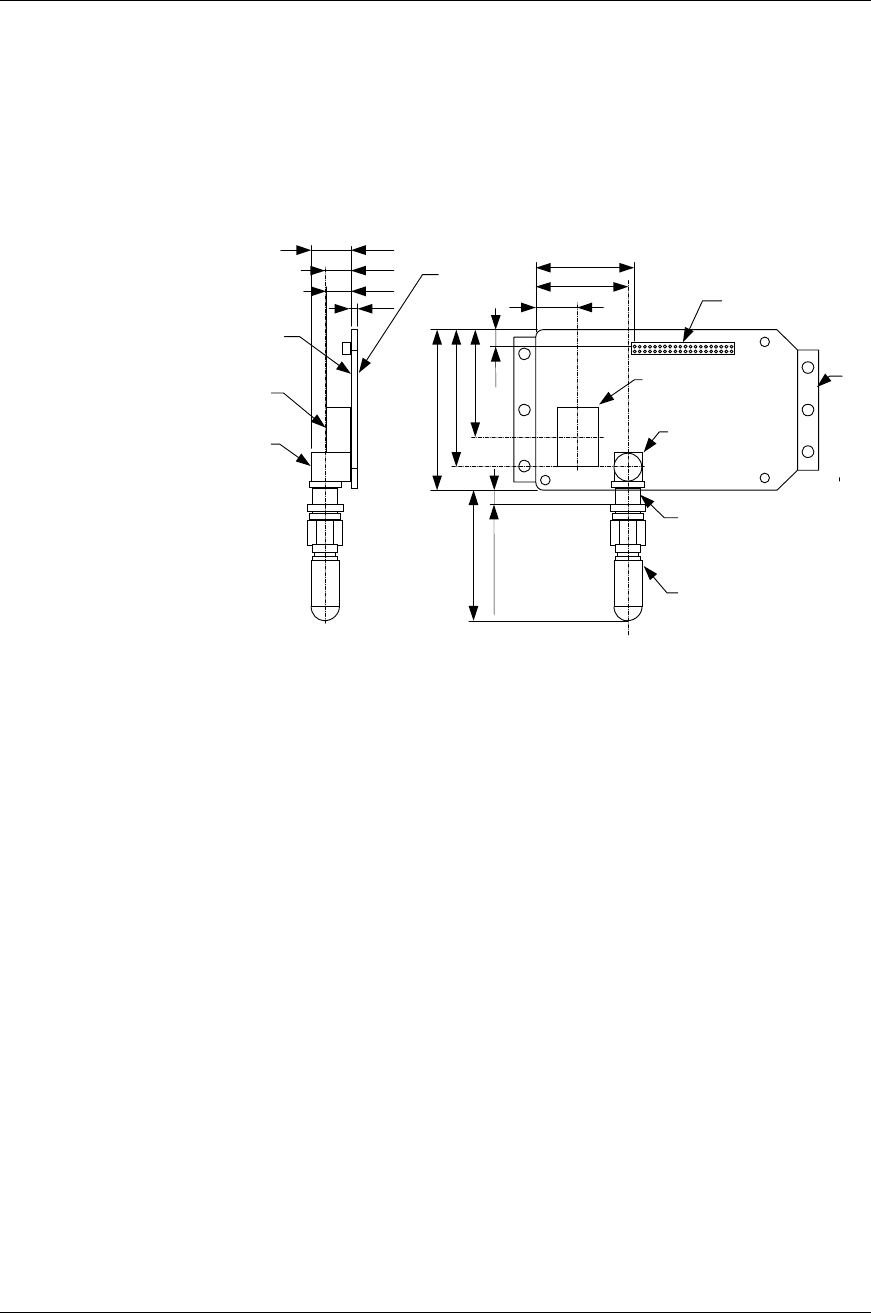
6.3 Component placements and dimensions
Components of important are the electrical interface (2x20 1.27mm header list) and
the antenna. There are 3 kinds of antennas (see Antennas) but only one is surface
mounted. The height of the components is max 3.0mm on the bottom side and
3.5mm on the topside except the antennas (see Figure 4).
Figure 4 - Connectors and component heights [mm].
6.4 Weight
With internal antenna: 18g
With antenna stub: 24g
With antenna on a cable: 39g
Mounting wings can be
removed by V-Cut
24.600
23.000
10.500
10.000
6.400
6.300
1.600
1
2
39
40
40.400
34.400
27.000
4.300
32.400
2.500 – Max panel thickness
2x20 1.270 pin socket for
interfacing the module. Bottom
and top entry
10.000x15.000 SMD Antenna,
not mounted if another antenna
is used.
SMA connector mounted
if a ¼ λ antenna or cable
antenna is used.
∅6.500 – Panel hole
¼ λ antenna
Secondary side,
max component
height 3.000
Primary side, max
component height
3.500 except antenna.
SMD antenna, only
one of the antennas
is mounted.
SMA connector for ¼ λ
antenna or cable
antenna, only one of the
antennas is mounted.

17
Chapter 7
Regulatory Information
7.1 Declaration of Conformity
We, connectBlue AB, of
Stora Varvsgatan 11 N:1
SE-211 19 Malmö, Sweden
declare under our sole responsibility that our product conforms to the following
Product Specifications:
R&TTE Directive 1999/5/EC and EMC Directive: 89/336/EEC
ETS 300 826 and EN 300 328-2
Low Voltage Directive: 73/23/EEC
EN 61131-2
7.2 FCC
FCC Statement
This device complies with Part 15 of the FCC Rules. Operation is subject to the
following two conditions: (1) this device may not cause harmful interference, and (2)
this device must accept any interference received, including interference that may
cause undesired operation.
NOTE: This equipment has been tested and found to comply with the limits for a Class B
digital device, pursuant to Part 15 of the FCC Rules. These limits are designed to
provide reasonable protection against harmful interference in a residential
installation. This equipment generates, uses and can radiate radio frequency energy
and, if not installed and used in accordance with the instructions, may cause harmful
interference to radio communications. However, there is no guarantee that
interference will not occur in a particular installation. If this equipment does cause
harmful interference to radio or television reception, which can be determined by
turning the equipment off and on, the user is encouraged to try to correct the
interference by one or more of the following measures:
• Reorient or relocate the receiving antenna
• Increase the separation between the equipment and receiver
• Connect the equipment into an outlet on a circuit different from that to which the
receiver is connected
• Consult the dealer or an experienced radio/TV technician for help

18
Labeling Requirements for End Product
For an end product using the OEM Serial Port Adapter or the OEM Bluetooth
Enabler there must be a label containing, at least, the following information:
The label must be affixed on an exterior surface of the end product such that it will
be visible upon inspection in compliance with the modular approval guidelines
developed by the FCC.
In addition, the user manual for the end product must contain the following
information:
“This device complies with Part 15 of the FCC Rules. Operation is subject to the
following two conditions: (1) this device may not cause harmful interference, and (2)
this device must accept any interference received, including interference that may
cause undesired operation.”
RF-exposure statement
This mobile modular transmitter must have a separation distance of at least 20cm
between the antenna and the body of the user or nearby persons.
With a separation distance of 20cm or more, the MPE limits are well above the
potential this module is capable to produce.
Antenna
When using the module equipped with the “Coaxial cable antenna” or the “Stub
antenna” the antenna is fixed and cannot be removed or replaced by the end user.
Caution
Any changes or modifications NOT explicitly APPROVED by connectBlue AB could
cause the module to cease to comply with FCC rules part 15, and thus void the
user’s authority to operate the equipment.
This device contains
FCC ID:PVH000501