u blox Malmo 071902 Bluetooth IO Module User Manual
u-blox Malmo AB Bluetooth IO Module Users Manual
UserManual.wiki
>
u blox Malmo
>
071902 User Manual
Users Manual
Navigation menu
Upload a User Manual
Namespaces
Wiki Guide
HTML
PDF
Info
Views
User Manual
Discussion / Help
Navigation

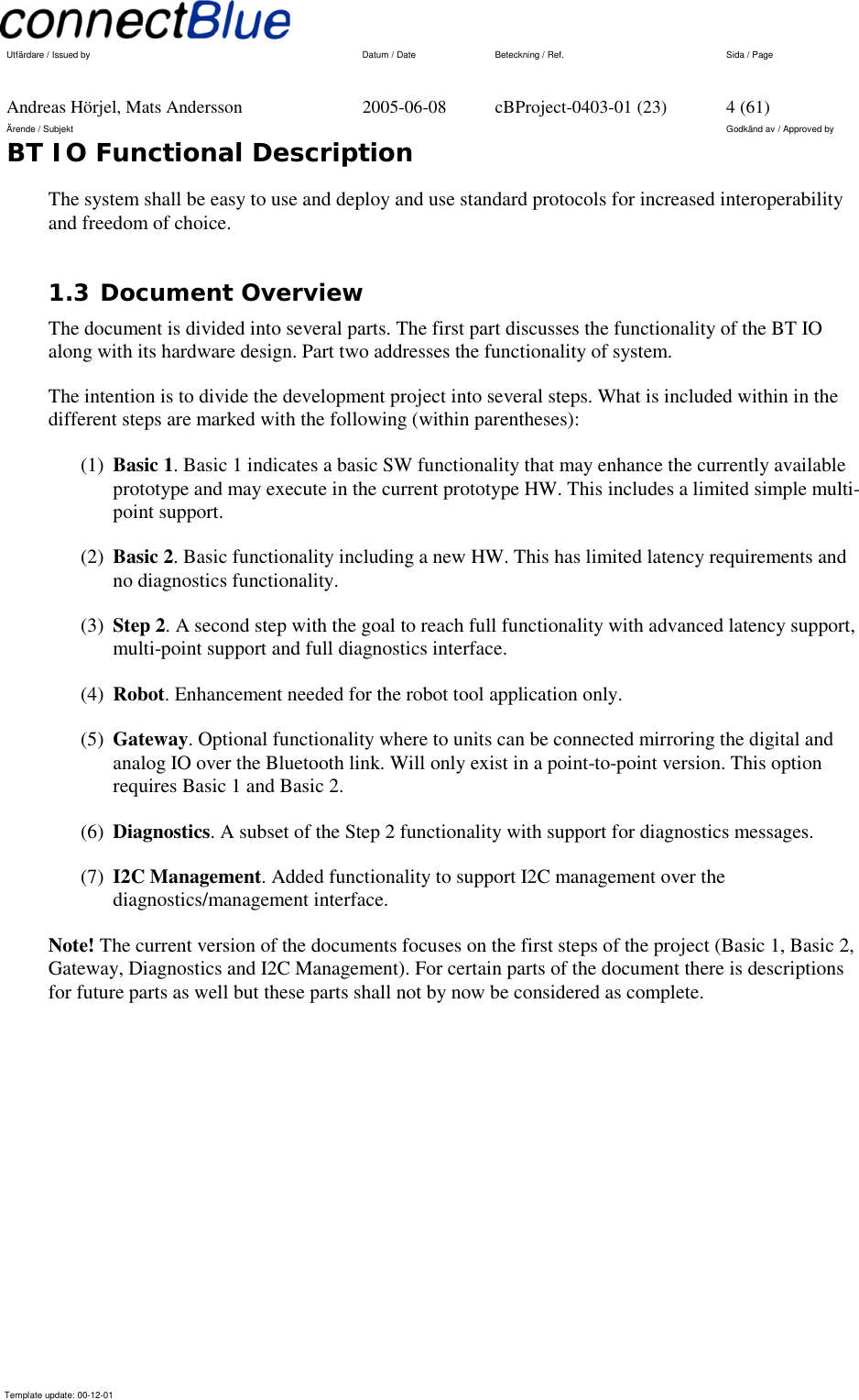
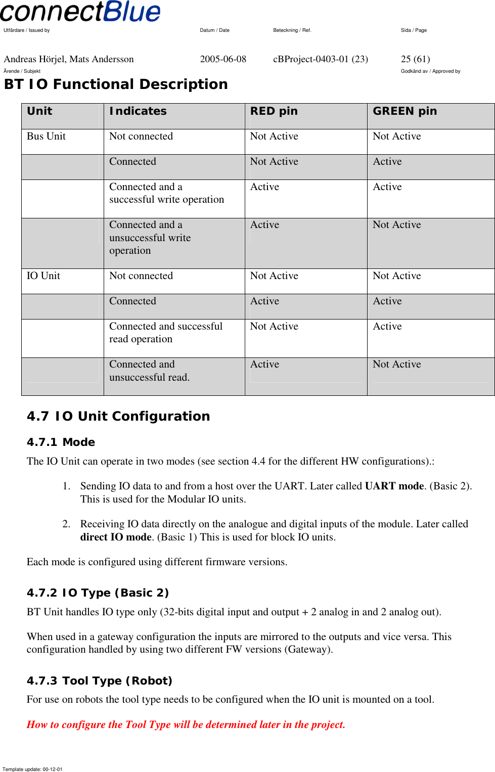
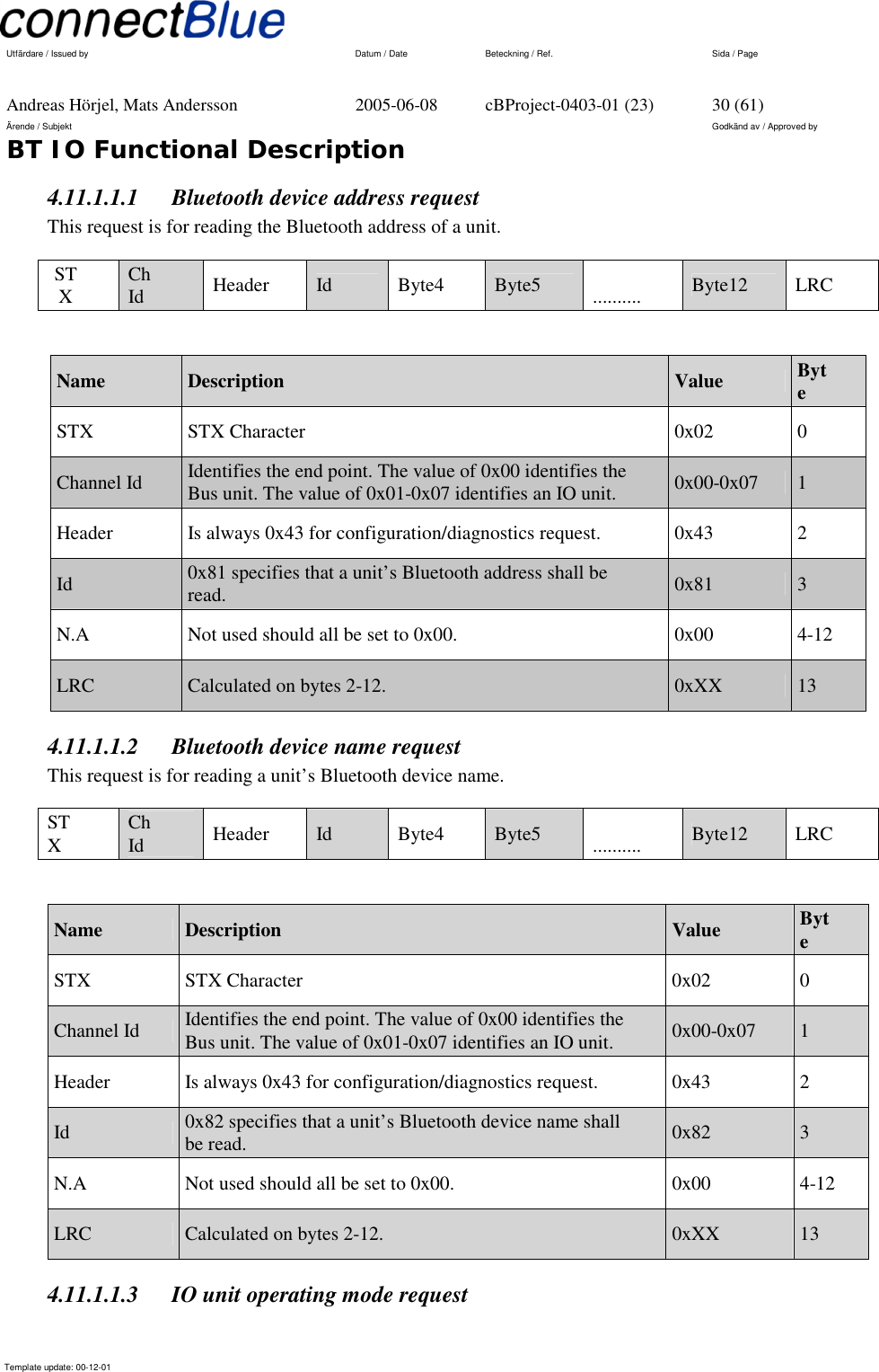
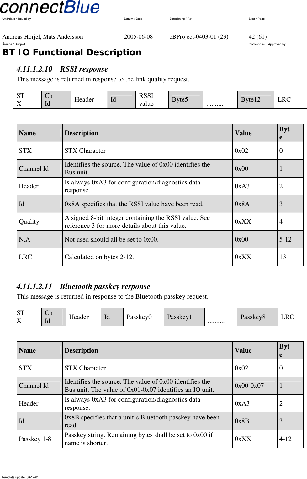
![Utfärdare / Issued by Datum / Date Beteckning / Ref. Sida / Page Andreas Hörjel, Mats Andersson 2005-06-08 cBProject-0403-01 (23) 10 (61) Ärende / Subjekt Godkänd av / Approved by BT IO Functional Description Template update: 00-12-01 4.2 Hardware (Basic 2) 4.2.1 Block Diagram ADR[0..18]PowersupplyCSR BC352239ARadio & Baseband Bluetooth ICFLASH 8MbitDATA[0..15]+3V+3V-PA VinPower supply+1V8Vin(2.2V - 4.2V)ATMEL T7024PA/LNATX-BALUN1613TX/RX-switchTX-BTX-ARF-inPIO-1PIO-0TX/RXcontrolAnalog -I/ODigital-I/OUARTSPIRESET-nAnalogInterface444External Antenna connectorJ1OptionalInternal AntennaJ2J3Module Interface19 Figure 3 - HW Block Diagram](https://usermanual.wiki/u-blox-Malmo/071902/User-Guide-551382-Page-10.png)
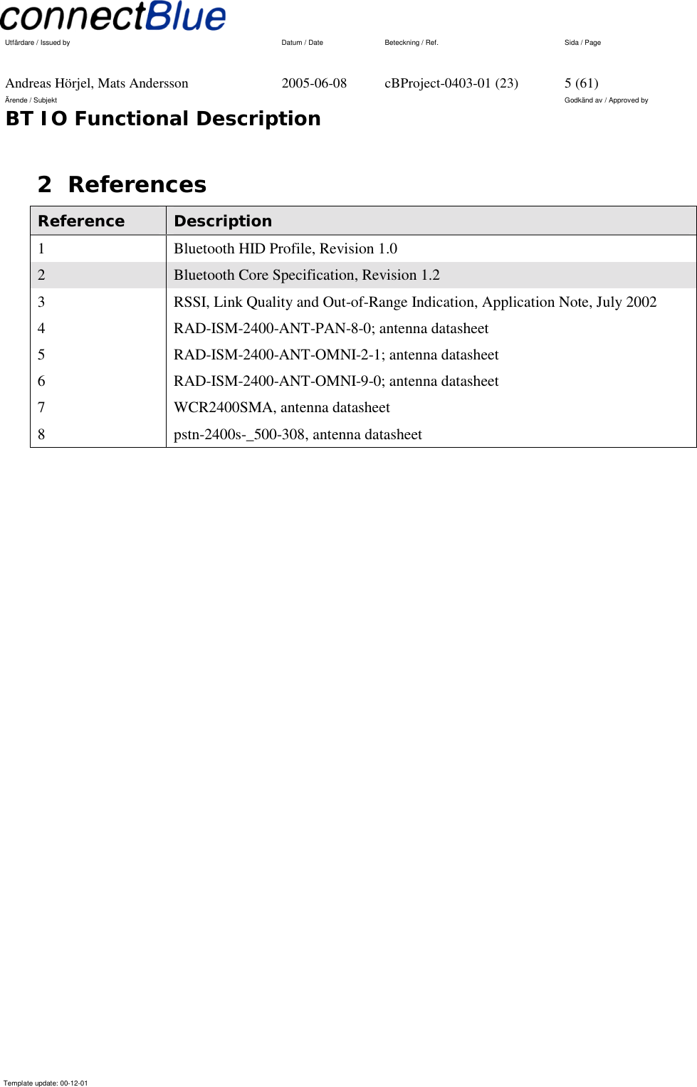
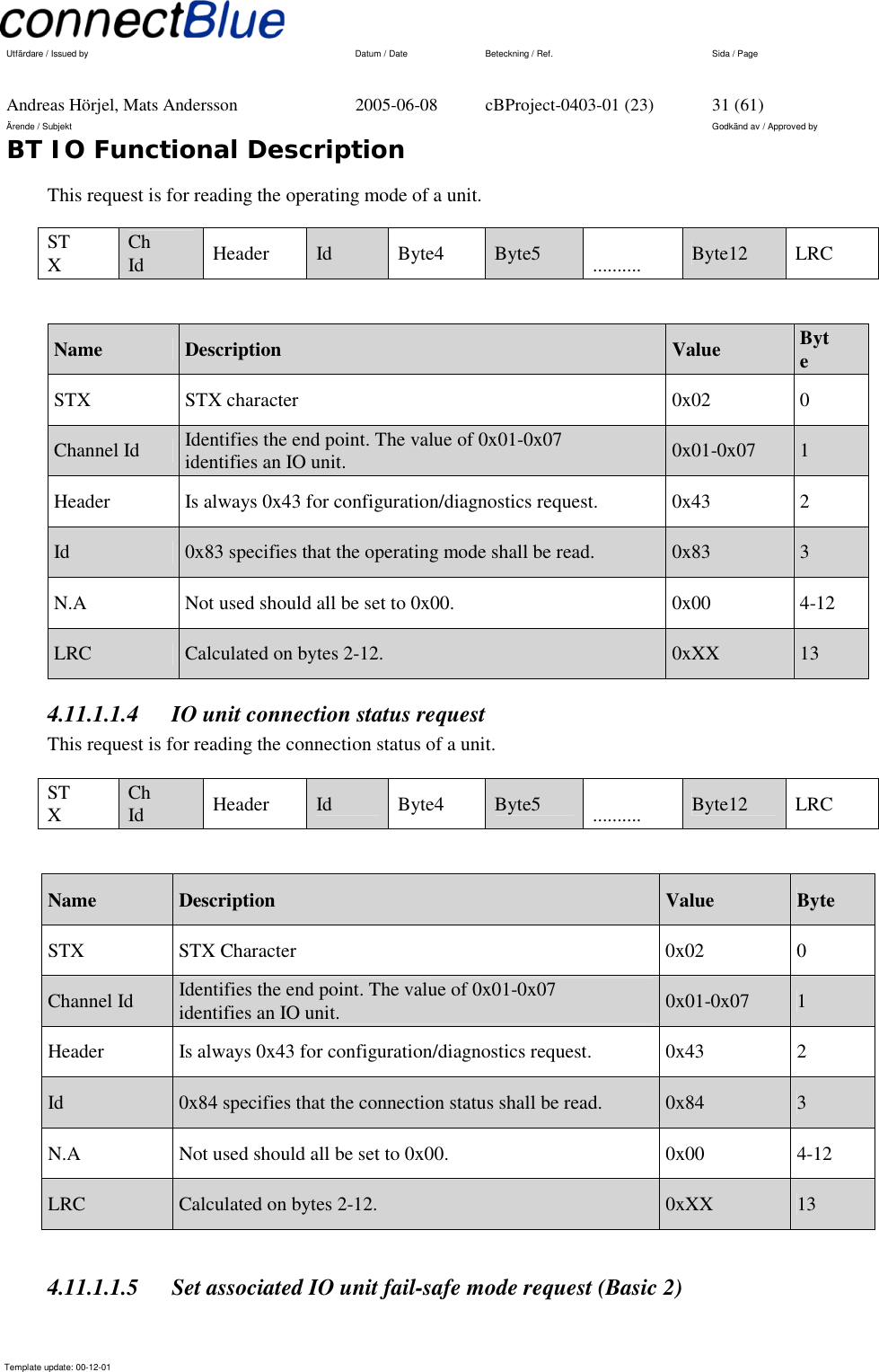
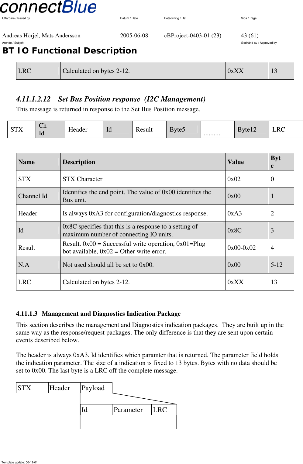
![Utfärdare / Issued by Datum / Date Beteckning / Ref. Sida / Page Andreas Hörjel, Mats Andersson 2005-06-08 cBProject-0403-01 (23) 29 (61) Ärende / Subjekt Godkänd av / Approved by BT IO Functional Description Template update: 00-12-01 Bus Unit Conf.data Application Filter Data UART Conf Bluetooth to IO unit Figure 14 - Displays how configuration messages are routed in a Bus unit. 4.11.1 Management and Diagnostics messages The protocol defines telegrams in format defined below. The telegrams start with a STX character and a channel identifier, which is used for multiplexing multiple IO units. The second part of the telegram is a basic HID packet, which contents depend on the purpose. Channel Id HID control packet STX The HID telegrams contents are described in HID specification version 1.0 [1]. A short description of the telegrams used is described below. Note! Management and Diagnostics messages for the Robot option are not fully described in this document. Will be done when it are to be implemented. 4.11.1.1 Management and Diagnostics request package This package is for sending diagnostics and configuration parameters to the BT IO. The header is always 0x43. Id identifies which paramter to return, the parameter field is a sub specification field to specify certain data pointed to by Id. The message is always 13 bytes long, none used fields should be set to 0x00. The last byte is a LRC of the complete message. Header Payload Id Parameters LRC](https://usermanual.wiki/u-blox-Malmo/071902/User-Guide-551382-Page-29.png)
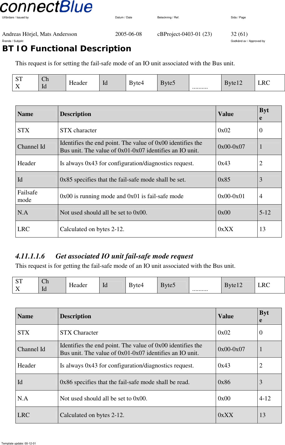
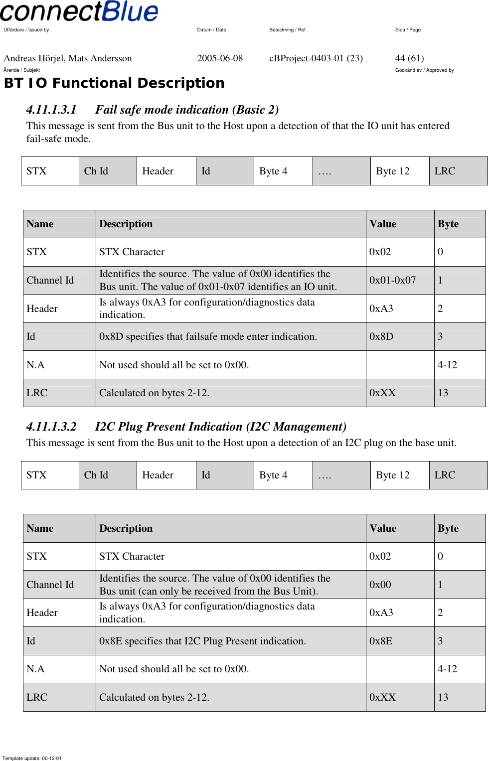
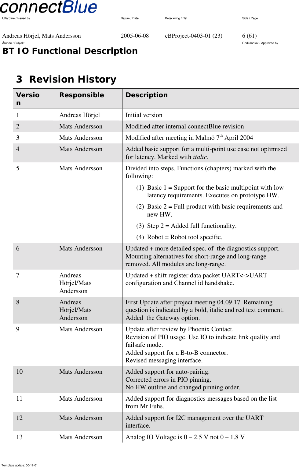
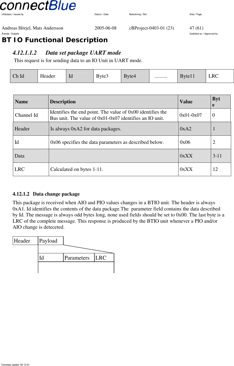
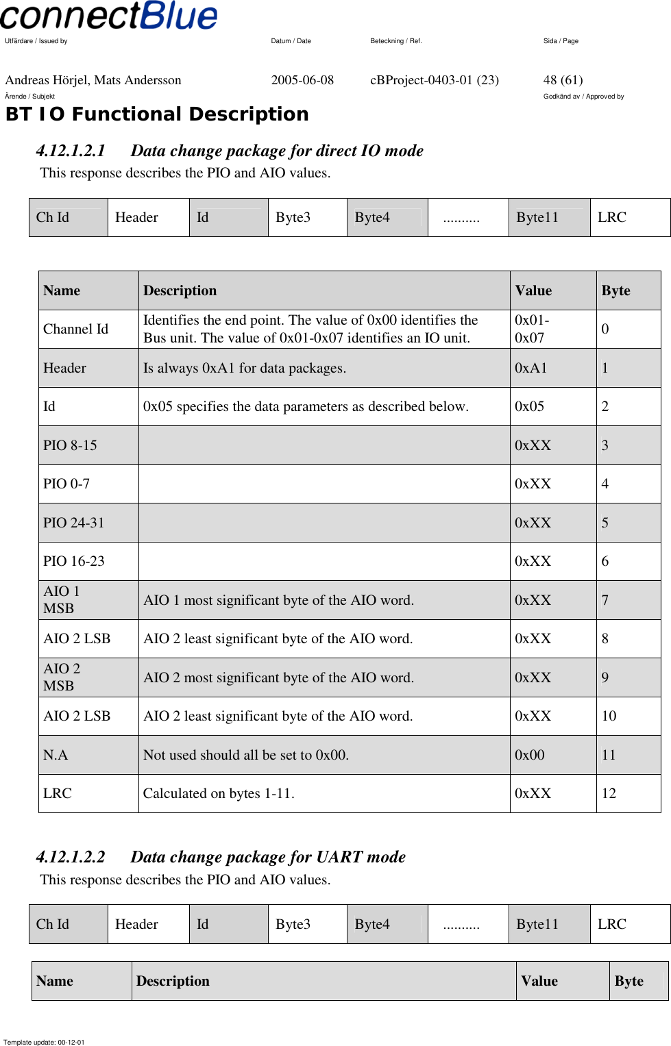
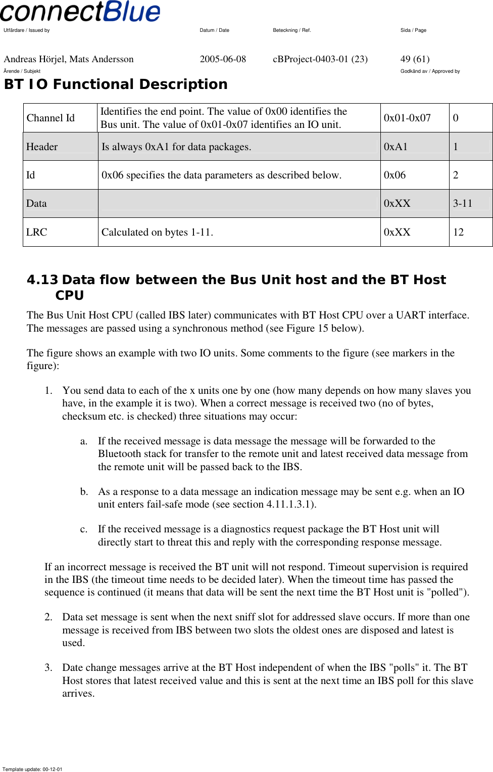
![Utfärdare / Issued by Datum / Date Beteckning / Ref. Sida / Page Andreas Hörjel, Mats Andersson 2005-06-08 cBProject-0403-01 (23) 45 (61) Ärende / Subjekt Godkänd av / Approved by BT IO Functional Description Template update: 00-12-01 4.11.2 LRC The LRC field is one byte, containing an 8-bit binary value. The LRC value is calculated by the transmitting device, which appends the LRC to the message. The receiving device calculates an LRC during receipt of the message, and compares the calculated value to the actual value it received in the LRC field. If the two values are not equal, an error results. The LRC is calculated by adding together successive 8-bit bytes of the message, discarding any carries, and then two’s complementing the result. The LRC is calculated on the complete message excluding the channel identifier. 4.12 Data Communication between the host and the Bus unit (Basic 2) This data communication is used for setting/receiving data to/from the Bus units associated IO units. The protocol is defined in the following sections. 4.12.1 Data messages The telegrams start with a channel identifier, which is used for multiplexing multiple IO units. The second part of the telegram is a basic HID data packet, which contents depend on the purpose. Channel Id HID data packet The HID telegrams contents are described in HID specification version 1.0 [1]. A short description of the telegrams used is described below. 4.12.1.1 Data set package This package is for writing AIO and PIO values to a BTIO unit. The header is always 0xA1. Id identifies the contents of the data package.The parameter field is contains the data described by Id. The message is always odd bytes long, none used fields should be set to 0x00. The last byte is a LRC of the complete message. This request is send by the host to the bus unit when a set action is requiered. Header Payload Id Parameters LRC](https://usermanual.wiki/u-blox-Malmo/071902/User-Guide-551382-Page-45.png)
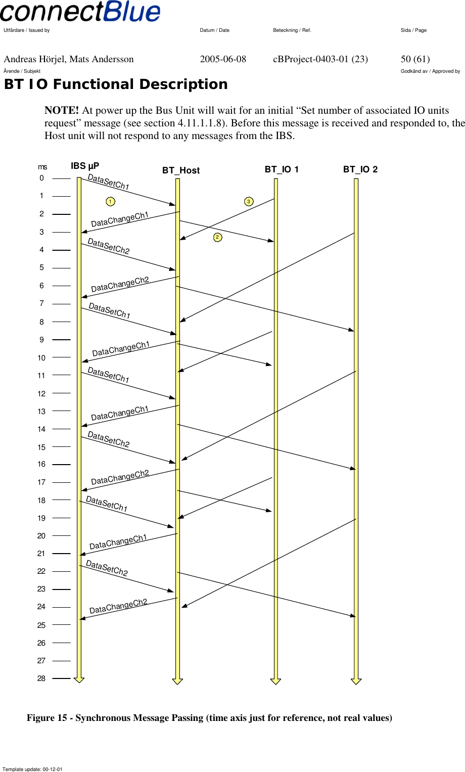
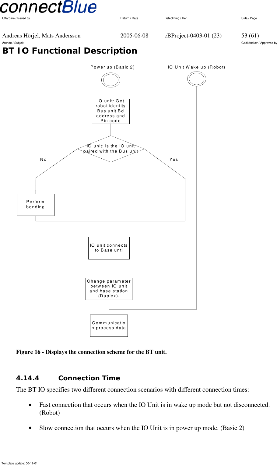
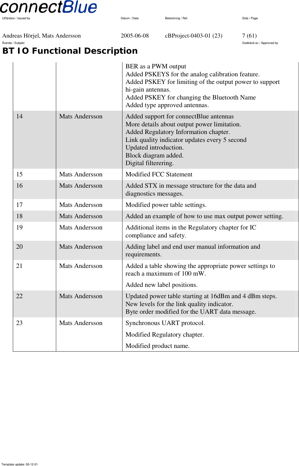
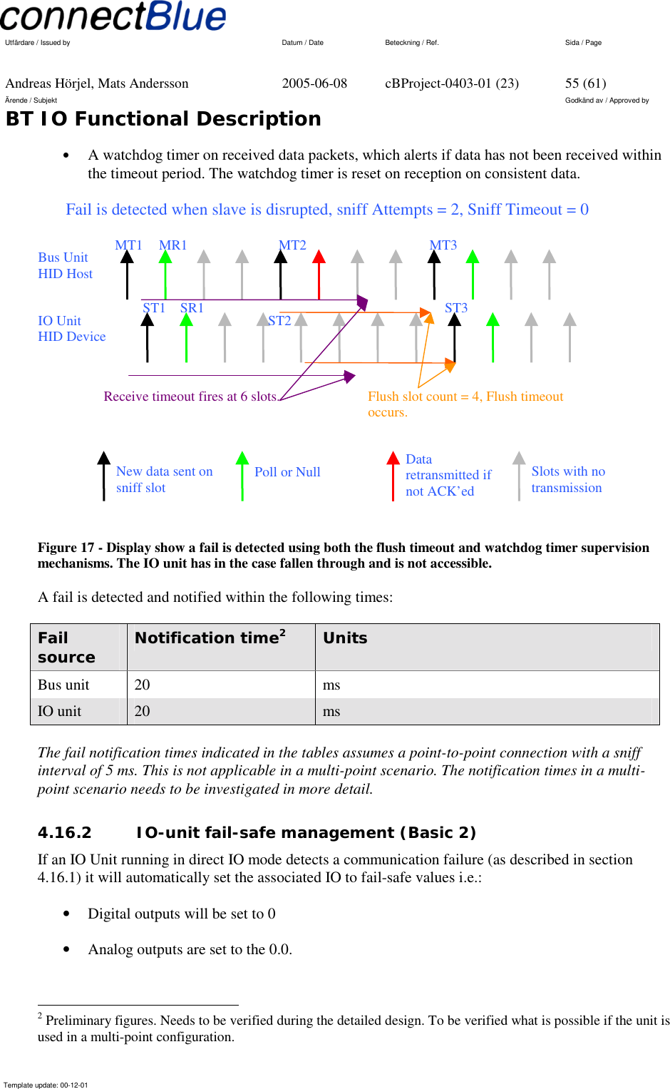
![Utfärdare / Issued by Datum / Date Beteckning / Ref. Sida / Page Andreas Hörjel, Mats Andersson 2005-06-08 cBProject-0403-01 (23) 54 (61) Ärende / Subjekt Godkänd av / Approved by BT IO Functional Description Template update: 00-12-01 The fast connection mode is realized using sniff mode with a long sniff period (100ms). This means that the IO Unit is synchronized to the Bus Unit, which enables fast activation into running mode and communicating data. (Robot) Connection mode Connection time [ms]1 Fast connection 100 Slow connection 3000 4.14.5 Disconnection (Robot) The IO Unit will repeatedly be disconnected from the Bus Unit, i.e. when changing tools on the robot or when maintenance is performed. The IO Unit has no external power source during this time, which will force the power up mode when reconnecting. It is more optimal if the unit goes to wake up mode on disconnection, which enables fast communication establishment when the IO Unit is reconnected. The IO Unit can operate in wake up mode (sniff mode with long sniff period), still being synchronized to the Bus Unit, when the IO is disconnected. Wake up mode uses a longer sniff period; a long sniff period (100ms) consumes less power than a short sniff period (5ms), than when the communication is running. Wake up mode allows the IO Unit to quickly be reactivated in the Bus Unit’s piconet due to that it is synchronized with the Bus Unit, however it demands some kind of power source. This can is realized with batteries or a super cap mounted on the IO Unit. The IO Unit will restart from power up mode when no super cap or battery power source is present. 4.15 Security (Basic 2) The Bluetooth communication link is protected by Bluetooth’s security mechanisms, encryption and authentication. Neither the IO Unit nor the Bus Unit is discoverable when using the connection scheme described above, which adds more security to the communication link. Unauthorized Bluetooth units cannot find undiscoverable units, which block these units from affecting the transmitted information. 4.16 Fail-safe mode (Basic 2) 4.16.1 Fail-safe detection Fail-safe mode is entered whenever a fail is detected in the Bluetooth communication. A fail can occur due to power failure, radio disruption or radio interference. Fails are detected using the following Bluetooth supervision mechanisms: • A standard Flush Timeout, which alerts if data has not been transmitted within the timeout period. 1 Preliminary. Needs to be verified.](https://usermanual.wiki/u-blox-Malmo/071902/User-Guide-551382-Page-54.png)
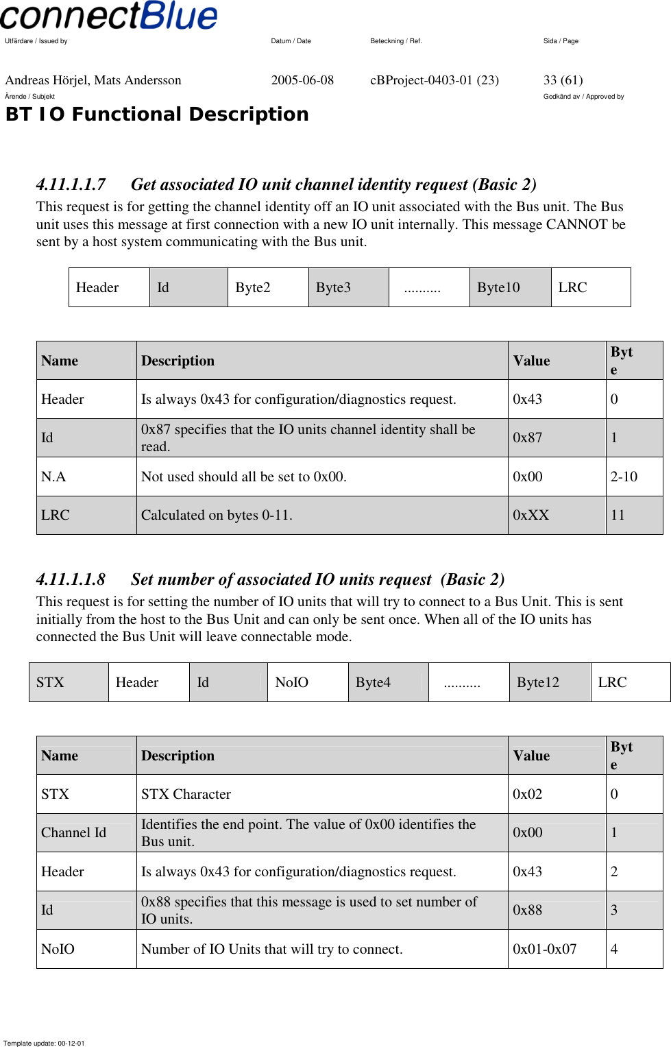
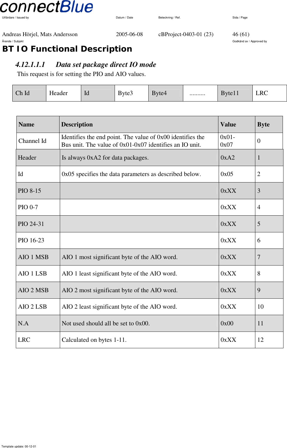
![Utfärdare / Issued by Datum / Date Beteckning / Ref. Sida / Page Andreas Hörjel, Mats Andersson 2005-06-08 cBProject-0403-01 (23) 58 (61) Ärende / Subjekt Godkänd av / Approved by BT IO Functional Description Template update: 00-12-01 Power mode Average5 Units Run mode communication full speed 45 mA Run mode idle [IO unit = slave] 22 mA Run mode idle [Bus unit = master] 5 mA Wake up mode sniff period 100ms [IO unit] 1 mA Power up mode disconnected [IO unit] 0 mA 5 These figures are preliminary and needs to be verified in the design phase.](https://usermanual.wiki/u-blox-Malmo/071902/User-Guide-551382-Page-58.png)